EP1541970A1 - Procédé de compensation d'une anisotropie dans un capteur de rotation inertiel à cloche vibrante - Google Patents
Procédé de compensation d'une anisotropie dans un capteur de rotation inertiel à cloche vibrante Download PDFInfo
- Publication number
- EP1541970A1 EP1541970A1 EP04292888A EP04292888A EP1541970A1 EP 1541970 A1 EP1541970 A1 EP 1541970A1 EP 04292888 A EP04292888 A EP 04292888A EP 04292888 A EP04292888 A EP 04292888A EP 1541970 A1 EP1541970 A1 EP 1541970A1
- Authority
- EP
- European Patent Office
- Prior art keywords
- electrodes
- gain
- anisotropy
- bell
- electrode
- Prior art date
- Legal status (The legal status is an assumption and is not a legal conclusion. Google has not performed a legal analysis and makes no representation as to the accuracy of the status listed.)
- Granted
Links
- 238000000034 method Methods 0.000 title claims abstract description 17
- 238000001514 detection method Methods 0.000 claims abstract description 14
- 230000010287 polarization Effects 0.000 claims abstract description 7
- 238000012545 processing Methods 0.000 abstract description 11
- VYPSYNLAJGMNEJ-UHFFFAOYSA-N Silicium dioxide Chemical compound O=[Si]=O VYPSYNLAJGMNEJ-UHFFFAOYSA-N 0.000 description 2
- 238000012937 correction Methods 0.000 description 2
- 238000005452 bending Methods 0.000 description 1
- 238000006073 displacement reaction Methods 0.000 description 1
- 238000012423 maintenance Methods 0.000 description 1
- 238000004519 manufacturing process Methods 0.000 description 1
- 238000005259 measurement Methods 0.000 description 1
- 239000002184 metal Substances 0.000 description 1
- 230000003287 optical effect Effects 0.000 description 1
- 244000045947 parasite Species 0.000 description 1
- 230000003071 parasitic effect Effects 0.000 description 1
- 239000000377 silicon dioxide Substances 0.000 description 1
Images
Classifications
-
- G—PHYSICS
- G01—MEASURING; TESTING
- G01C—MEASURING DISTANCES, LEVELS OR BEARINGS; SURVEYING; NAVIGATION; GYROSCOPIC INSTRUMENTS; PHOTOGRAMMETRY OR VIDEOGRAMMETRY
- G01C19/00—Gyroscopes; Turn-sensitive devices using vibrating masses; Turn-sensitive devices without moving masses; Measuring angular rate using gyroscopic effects
- G01C19/56—Turn-sensitive devices using vibrating masses, e.g. vibratory angular rate sensors based on Coriolis forces
- G01C19/567—Turn-sensitive devices using vibrating masses, e.g. vibratory angular rate sensors based on Coriolis forces using the phase shift of a vibration node or antinode
- G01C19/5691—Turn-sensitive devices using vibrating masses, e.g. vibratory angular rate sensors based on Coriolis forces using the phase shift of a vibration node or antinode of essentially three-dimensional vibrators, e.g. wine glass-type vibrators
-
- G—PHYSICS
- G01—MEASURING; TESTING
- G01C—MEASURING DISTANCES, LEVELS OR BEARINGS; SURVEYING; NAVIGATION; GYROSCOPIC INSTRUMENTS; PHOTOGRAMMETRY OR VIDEOGRAMMETRY
- G01C25/00—Manufacturing, calibrating, cleaning, or repairing instruments or devices referred to in the other groups of this subclass
- G01C25/005—Manufacturing, calibrating, cleaning, or repairing instruments or devices referred to in the other groups of this subclass initial alignment, calibration or starting-up of inertial devices
Definitions
- the present invention relates to a compensation method of anisotropy in an inertial rotation sensor with vibrating bell.
- Inertial rotation sensors comprising a vibrating bell, usually a bell hemispherical, whose surface is metallized to receive a bias voltage, the bell having an edge facing which extend electrodes carried by a basement.
- the electrodes are divided into control electrodes and in detection electrodes. Command signals are applied to the control electrodes so to provoke in the vibrating bell vibrations causing deformations of the bell whose orientation is sensitive to a rotation of the sensor.
- Electrodes of detection are used to measure the orientation of the deformations of the bell and deduce by appropriate treatment the rotational movements of the sensor.
- each electrode is function on the one hand of the electrode surface and on the other hand the value of the gap between the electrode and the edge opposite the vibrating bell.
- the electrodes of surface differences or gap causing gain differences between the electrodes that these are control electrodes or detection electrodes.
- each electrode is connected to a chain of treatment and the different treatment chains may also differ from each other gain. This generally results in anisotropy both the command and the detection. This anisotropy is a source of error in the calculation of movements rotation of the sensor.
- An object of the invention is to propose a method to minimize the consequences of anisotropy in an inertial rotation sensor with vibrating bell.
- a method of compensating an anisotropy in an inertial rotation sensor comprising a metallic vibrating bell to which is applied a bias voltage, the vibrating bell having a edge opposite which control electrodes extend and detection electrodes carried by a base, the method comprising the steps of measuring at least a component of the anisotropy between the electrodes of detection and apply to these electrodes a fraction of the bias voltage according to measured deviations between the electrodes.
- the anisotropy is measured by a measure of a difference gain between the electrodes. So, by one measure, all the irregularities resulting from the different components of the gain (air gap, surface of electrodes ).
- the difference in gain between the electrodes is measured by multiplexing using a processing line unique for a group of electrodes. So, for this group of electrodes, it eliminates not only errors derived from the structure anisotropy of the sensor but also the anisotropy component from the treatment of the signal.
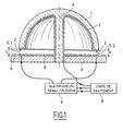
- the compensation method according to the invention applies to a rotation sensor inertia comprising in known manner a bell vibrating 1, here a hemispherical bell made in silica and fixed by a rod 4 to a base 3.
- the surface bell 1 and the end face 7 of the bell bell edge and stem 4 are covered with a layer of metal 2 connected to a processing unit 8 for receive a DC bias voltage.
- the base 3 carries a guard electrode 6 as well as electrodes control and detection electrodes, in general eight in total, extending opposite the edge 7 of the bell 1 and regularly distributed around the axis of the bell 1.
- the figure represents only two electrodes 5.1 and 5.2 diametrically opposite. These can indifferently be control electrodes or electrodes detection.
- the distance between electrodes and the edge 7 of the bell has intentionally been exaggerated to better illustrate the difference in size of the gap E between the electrode 5.1 and the edge 7 of the bell compared to the air gap e between the electrode 5.2 and the edge 7 of the bell.
- the electrodes are connected to a multiplexer / demultiplexer 9 himself connected to the unit of treatment 8.
- the processing unit ensures first, through the multiplexer / demultiplexer 9, a measuring the gain for each of the electrodes and determines the electrode with the lowest gain and the electrode to which the most gain corresponds strong. A calculation is then performed in the unit of processing 8 to determine the voltage fraction of polarization that it is necessary to apply to the electrode gain the strongest to bring this gain back to the value the lowest gain. For each of the others electrodes, a similar calculation is performed to determine, from the bias voltage fraction applied to the strongest gain electrode, a fraction of polarization voltage of the same sign and having a value in inverse function of the gain difference compared to the lowest gain electrode so that all the electrodes are thus brought back to the same gain.
- the invention has been described in relation to a single processing unit, one can implement the method according to the invention in relation with conventional treatment systems having a processing chain associated with each electrode.
- the gains can be measured simultaneously for each of the electrodes and a comparison is made between the gains measured by the different processing lines to determine the fractions bias voltage to be applied to each electrodes, which makes it possible to correct the errors due to the structural anisotropy of the sensor.
- the method according to the invention can also be applied to a sensor whose electrodes extend opposite the side face of the bell along the edge thereof.
- the process according to the invention can be applied either in workshop with a simple storing, in a sensor control unit, polarization voltage fractions to be applied to each electrodes, either be incorporated into the unit of sensor control for implementation during initialization of the sensor prior to its use.
- polarization voltage fractions to be applied to each electrodes, either be incorporated into the unit of sensor control for implementation during initialization of the sensor prior to its use.
- it can be realized a simplified correction by measuring only one of the components of anisotropy, for example the differences between air gaps, by mechanical means or optical and ensure only the compensation of the anisotropy of this component.
Landscapes
- Engineering & Computer Science (AREA)
- Physics & Mathematics (AREA)
- General Physics & Mathematics (AREA)
- Radar, Positioning & Navigation (AREA)
- Remote Sensing (AREA)
- Manufacturing & Machinery (AREA)
- Gyroscopes (AREA)
- Pressure Sensors (AREA)
Abstract
Description
Claims (5)
- Procédé de compensation d'une anisotropie dans un capteur de rotation inertiel comportant une cloche vibrante métallisée (1) à laquelle est appliquée une tension de polarisation, la cloche vibrante ayant un bord (7) en regard duquel s'étendent des électrodes de commande et des électrodes de détection (5.1, 5.2) portées par un socle (3), caractérisé en ce qu'il comporte les étapes de mesurer au moins une composante de l'anisotropie entre les électrodes de détection et d'appliquer à ces électrodes une fraction de la tension de polarisation en fonction d'écarts mesurés entre les électrodes.
- Procédé selon la revendication 1, caractérisé en ce que l'anisotropie est mesurée par une mesure d'une différence de gain entre les électrodes.
- Procédé selon la revendication 2, caractérisé en ce qu'il comporte les étapes de mesurer le gain de toutes les électrodes, d'appliquer à une électrode de gain le plus fort une fraction de tension de polarisation nécessaire pour équilibrer le gain avec une électrode de gain le plus faible et appliquer aux autres électrodes une fraction de tension de polarisation de même signe ayant une valeur en fonction inverse de la différence de gain par rapport à l'électrode de gain le plus faible.
- Procédé selon la revendication 2, caractérisé en ce qu'il comporte les étapes de comparer le gain entre des électrodes (5.1, 5.2) diamétralement opposées et appliquer à ces électrodes des fractions de tension de polarisation de mêmes valeurs et ayant des signes opposés.
- Procédé selon la revendication 2, caractérisé en ce que la différence de gain entre les électrodes est mesurée par multiplexage au moyen d'une chaíne à traitement unique pour un groupe d'électrodes.
Applications Claiming Priority (2)
| Application Number | Priority Date | Filing Date | Title |
|---|---|---|---|
| FR0314514 | 2003-12-11 | ||
| FR0314514A FR2863701B1 (fr) | 2003-12-11 | 2003-12-11 | Procede de compensation d'une anisotropie dans un capteur de rotation inertiel a cloche vibrante |
Publications (2)
| Publication Number | Publication Date |
|---|---|
| EP1541970A1 true EP1541970A1 (fr) | 2005-06-15 |
| EP1541970B1 EP1541970B1 (fr) | 2008-04-09 |
Family
ID=34508637
Family Applications (1)
| Application Number | Title | Priority Date | Filing Date |
|---|---|---|---|
| EP04292888A Active EP1541970B1 (fr) | 2003-12-11 | 2004-12-06 | Procédé de compensation d'une anisotropie dans un capteur de rotation inertiel à cloche vibrante |
Country Status (5)
| Country | Link |
|---|---|
| US (1) | US7222513B2 (fr) |
| EP (1) | EP1541970B1 (fr) |
| AT (1) | ATE391899T1 (fr) |
| DE (1) | DE602004012951T2 (fr) |
| FR (1) | FR2863701B1 (fr) |
Families Citing this family (6)
| Publication number | Priority date | Publication date | Assignee | Title |
|---|---|---|---|---|
| FR2936049B1 (fr) * | 2008-09-16 | 2010-09-17 | Sagem Defense Securite | Resonateur a metallisation partielle pour detecteur de parametre angulaire. |
| US8631702B2 (en) | 2010-05-30 | 2014-01-21 | Honeywell International Inc. | Hemitoroidal resonator gyroscope |
| WO2012067534A1 (fr) | 2010-11-19 | 2012-05-24 | Общество С Ограниченной Ответственностью "Инналабс" | Gyroscope vibrant de coriolis axisymétrique et variantes |
| CN106849899A (zh) * | 2017-01-05 | 2017-06-13 | 东南大学 | 微单壳体谐振器 |
| US12012327B2 (en) | 2020-03-12 | 2024-06-18 | Honeywell International Inc. | Methods for vibration immunity to suppress bias errors in sensor devices |
| US11874112B1 (en) | 2022-10-04 | 2024-01-16 | Enertia Microsystems Inc. | Vibratory gyroscopes with resonator attachments |
Citations (2)
| Publication number | Priority date | Publication date | Assignee | Title |
|---|---|---|---|---|
| FR2784180A1 (fr) * | 1998-07-29 | 2000-04-07 | Litton Systems Inc | Capteur vibratoire de position |
| FR2821422A1 (fr) * | 2001-02-23 | 2002-08-30 | Sagem | Resonateur mecanique planaire sensible selon un axe perpendiculaire a son plan |
Family Cites Families (5)
| Publication number | Priority date | Publication date | Assignee | Title |
|---|---|---|---|---|
| US4157041A (en) * | 1978-05-22 | 1979-06-05 | General Motors Corporation | Sonic vibrating bell gyro |
| US4951508A (en) * | 1983-10-31 | 1990-08-28 | General Motors Corporation | Vibratory rotation sensor |
| US5712427A (en) * | 1995-08-29 | 1998-01-27 | Litton Systems Inc. | Vibratory rotation sensor with scanning-tunneling-transducer readout |
| US5892152A (en) * | 1997-07-29 | 1999-04-06 | Litton Systems, Inc. | Multiple vibratory rotation sensors with multiplexed electronics |
| US5983719A (en) * | 1997-07-31 | 1999-11-16 | Litton Systems, Inc. | Low quantization method and apparatus for vibratory rotation sensors |
-
2003
- 2003-12-11 FR FR0314514A patent/FR2863701B1/fr not_active Expired - Fee Related
-
2004
- 2004-12-06 EP EP04292888A patent/EP1541970B1/fr active Active
- 2004-12-06 DE DE602004012951T patent/DE602004012951T2/de active Active
- 2004-12-06 AT AT04292888T patent/ATE391899T1/de not_active IP Right Cessation
- 2004-12-09 US US11/007,168 patent/US7222513B2/en active Active
Patent Citations (2)
| Publication number | Priority date | Publication date | Assignee | Title |
|---|---|---|---|---|
| FR2784180A1 (fr) * | 1998-07-29 | 2000-04-07 | Litton Systems Inc | Capteur vibratoire de position |
| FR2821422A1 (fr) * | 2001-02-23 | 2002-08-30 | Sagem | Resonateur mecanique planaire sensible selon un axe perpendiculaire a son plan |
Also Published As
| Publication number | Publication date |
|---|---|
| US7222513B2 (en) | 2007-05-29 |
| US20050126257A1 (en) | 2005-06-16 |
| FR2863701A1 (fr) | 2005-06-17 |
| EP1541970B1 (fr) | 2008-04-09 |
| ATE391899T1 (de) | 2008-04-15 |
| FR2863701B1 (fr) | 2006-01-13 |
| DE602004012951T2 (de) | 2009-05-28 |
| DE602004012951D1 (de) | 2008-05-21 |
Similar Documents
| Publication | Publication Date | Title |
|---|---|---|
| EP2181305B1 (fr) | Procede de determination d'une vitesse de rotation d'un capteur vibrant axisymetrique, et dispositif inertiel mettant en oeuvre le procede | |
| FR2699446A1 (fr) | Procédé et dispositif pour serrer ou desserrer, avec contrôle de l'angle de rotation, des systèmes de vissage. | |
| EP2304391B1 (fr) | Dispositif optique et procédé de mesure de rotation d'un objet | |
| EP0059295B1 (fr) | Cellule de mesure d'une force à effet radial | |
| WO1999041565A1 (fr) | Capteur d'extensiometrie destine a mesurer des deformations a calage mecanique de premiere pose et calibrage automatique en fonction de ce calage | |
| EP3071976A1 (fr) | Capteur a element sensible mobile ayant un fonctionnement mixte vibrant et pendulaire, et procedes de commande d'un tel capteur | |
| EP1541970B1 (fr) | Procédé de compensation d'une anisotropie dans un capteur de rotation inertiel à cloche vibrante | |
| CA2993477C (fr) | Dispositif de mesure inertielle a double suspension | |
| FR3033643A1 (fr) | Dispositif et procede pour detecter des defauts dans des zones de liaison entre des echantillons tels que des wafers | |
| EP0633100B1 (fr) | Outil de mesure d'un couple, tel qu'une clé dynamométrique électronique | |
| EP1385009B1 (fr) | Capteur inertiel compact | |
| WO2014096655A1 (fr) | Dispositif micro-electromecanique possedant au moins deux elements deformables de dimensions differentes | |
| EP2232273B1 (fr) | Procede de correction de gain d'un organe capacitif et dispositif de mise en oeuvre | |
| EP1353185A2 (fr) | Capteur inertiel à sonde de température intégrée | |
| FR3073281A1 (fr) | Capteur de vitesse de rotation comportant un substrat avec un plan principal d'extension ainsi qu'un procede de fabrication d'un capteur de vitesse de rotation | |
| EP0189721B1 (fr) | Procédé et dispositif de mesure de l'angle de braquage d'une roue avant de véhicule automobile | |
| EP2444774B1 (fr) | Dispositif inertiel comportant des capteurs inertiels de précisions différentes | |
| EP3388808B1 (fr) | Dispositif de detection de pression a decouplage mecanique | |
| FR2710415A1 (fr) | Détecteur angulaire de champ magnétique. | |
| WO2005050154A1 (fr) | Sonde d'incidence | |
| WO2023105142A1 (fr) | Dispositif et procédé de mesure du couple d'une chaîne de transmission | |
| EP1224110A1 (fr) | Module electronique de colonne de direction | |
| FR2673710A1 (fr) | Procede pour une lecture de forme d'un quelconque article deformable elastiquement, en particulier pour la lecture de contour d'un cercle ou entourage d'une monture de lunettes. | |
| FR2733657A1 (fr) | Bride de serrage de precision, et procede de serrage, de thyristors et composants electroniques de puissance analogues | |
| EP2388557B1 (fr) | Capteur optique de position angulaire absolue utilisant la technique de la polarimétrie |
Legal Events
| Date | Code | Title | Description |
|---|---|---|---|
| PUAI | Public reference made under article 153(3) epc to a published international application that has entered the european phase |
Free format text: ORIGINAL CODE: 0009012 |
|
| AK | Designated contracting states |
Kind code of ref document: A1 Designated state(s): AT BE BG CH CY CZ DE DK EE ES FI FR GB GR HU IE IS IT LI LT LU MC NL PL PT RO SE SI SK TR |
|
| AX | Request for extension of the european patent |
Extension state: AL BA HR LV MK YU |
|
| 17P | Request for examination filed |
Effective date: 20051004 |
|
| RAP1 | Party data changed (applicant data changed or rights of an application transferred) |
Owner name: SAGEM DEFENSE SECURITE |
|
| AKX | Designation fees paid |
Designated state(s): AT BE BG CH CY CZ DE DK EE ES FI FR GB GR HU IE IS IT LI LT LU MC NL PL PT RO SE SI SK TR |
|
| GRAP | Despatch of communication of intention to grant a patent |
Free format text: ORIGINAL CODE: EPIDOSNIGR1 |
|
| GRAS | Grant fee paid |
Free format text: ORIGINAL CODE: EPIDOSNIGR3 |
|
| GRAA | (expected) grant |
Free format text: ORIGINAL CODE: 0009210 |
|
| AK | Designated contracting states |
Kind code of ref document: B1 Designated state(s): AT BE BG CH CY CZ DE DK EE ES FI FR GB GR HU IE IS IT LI LT LU MC NL PL PT RO SE SI SK TR |
|
| REG | Reference to a national code |
Ref country code: GB Ref legal event code: FG4D Free format text: NOT ENGLISH |
|
| REG | Reference to a national code |
Ref country code: CH Ref legal event code: EP |
|
| REG | Reference to a national code |
Ref country code: IE Ref legal event code: FG4D Free format text: LANGUAGE OF EP DOCUMENT: FRENCH |
|
| REF | Corresponds to: |
Ref document number: 602004012951 Country of ref document: DE Date of ref document: 20080521 Kind code of ref document: P |
|
| PG25 | Lapsed in a contracting state [announced via postgrant information from national office to epo] |
Ref country code: SI Free format text: LAPSE BECAUSE OF FAILURE TO SUBMIT A TRANSLATION OF THE DESCRIPTION OR TO PAY THE FEE WITHIN THE PRESCRIBED TIME-LIMIT Effective date: 20080409 |
|
| NLV1 | Nl: lapsed or annulled due to failure to fulfill the requirements of art. 29p and 29m of the patents act | ||
| PG25 | Lapsed in a contracting state [announced via postgrant information from national office to epo] |
Ref country code: NL Free format text: LAPSE BECAUSE OF FAILURE TO SUBMIT A TRANSLATION OF THE DESCRIPTION OR TO PAY THE FEE WITHIN THE PRESCRIBED TIME-LIMIT Effective date: 20080409 Ref country code: ES Free format text: LAPSE BECAUSE OF FAILURE TO SUBMIT A TRANSLATION OF THE DESCRIPTION OR TO PAY THE FEE WITHIN THE PRESCRIBED TIME-LIMIT Effective date: 20080720 Ref country code: BG Free format text: LAPSE BECAUSE OF FAILURE TO SUBMIT A TRANSLATION OF THE DESCRIPTION OR TO PAY THE FEE WITHIN THE PRESCRIBED TIME-LIMIT Effective date: 20080709 Ref country code: PT Free format text: LAPSE BECAUSE OF FAILURE TO SUBMIT A TRANSLATION OF THE DESCRIPTION OR TO PAY THE FEE WITHIN THE PRESCRIBED TIME-LIMIT Effective date: 20080909 Ref country code: FI Free format text: LAPSE BECAUSE OF FAILURE TO SUBMIT A TRANSLATION OF THE DESCRIPTION OR TO PAY THE FEE WITHIN THE PRESCRIBED TIME-LIMIT Effective date: 20080409 |
|
| PG25 | Lapsed in a contracting state [announced via postgrant information from national office to epo] |
Ref country code: AT Free format text: LAPSE BECAUSE OF FAILURE TO SUBMIT A TRANSLATION OF THE DESCRIPTION OR TO PAY THE FEE WITHIN THE PRESCRIBED TIME-LIMIT Effective date: 20080409 Ref country code: PL Free format text: LAPSE BECAUSE OF FAILURE TO SUBMIT A TRANSLATION OF THE DESCRIPTION OR TO PAY THE FEE WITHIN THE PRESCRIBED TIME-LIMIT Effective date: 20080409 |
|
| REG | Reference to a national code |
Ref country code: IE Ref legal event code: FD4D |
|
| PG25 | Lapsed in a contracting state [announced via postgrant information from national office to epo] |
Ref country code: IS Free format text: LAPSE BECAUSE OF FAILURE TO SUBMIT A TRANSLATION OF THE DESCRIPTION OR TO PAY THE FEE WITHIN THE PRESCRIBED TIME-LIMIT Effective date: 20080809 |
|
| PG25 | Lapsed in a contracting state [announced via postgrant information from national office to epo] |
Ref country code: LT Free format text: LAPSE BECAUSE OF FAILURE TO SUBMIT A TRANSLATION OF THE DESCRIPTION OR TO PAY THE FEE WITHIN THE PRESCRIBED TIME-LIMIT Effective date: 20080409 Ref country code: CZ Free format text: LAPSE BECAUSE OF FAILURE TO SUBMIT A TRANSLATION OF THE DESCRIPTION OR TO PAY THE FEE WITHIN THE PRESCRIBED TIME-LIMIT Effective date: 20080409 Ref country code: DK Free format text: LAPSE BECAUSE OF FAILURE TO SUBMIT A TRANSLATION OF THE DESCRIPTION OR TO PAY THE FEE WITHIN THE PRESCRIBED TIME-LIMIT Effective date: 20080409 Ref country code: IE Free format text: LAPSE BECAUSE OF FAILURE TO SUBMIT A TRANSLATION OF THE DESCRIPTION OR TO PAY THE FEE WITHIN THE PRESCRIBED TIME-LIMIT Effective date: 20080409 Ref country code: SE Free format text: LAPSE BECAUSE OF FAILURE TO SUBMIT A TRANSLATION OF THE DESCRIPTION OR TO PAY THE FEE WITHIN THE PRESCRIBED TIME-LIMIT Effective date: 20080709 |
|
| PLBE | No opposition filed within time limit |
Free format text: ORIGINAL CODE: 0009261 |
|
| STAA | Information on the status of an ep patent application or granted ep patent |
Free format text: STATUS: NO OPPOSITION FILED WITHIN TIME LIMIT |
|
| PG25 | Lapsed in a contracting state [announced via postgrant information from national office to epo] |
Ref country code: SK Free format text: LAPSE BECAUSE OF FAILURE TO SUBMIT A TRANSLATION OF THE DESCRIPTION OR TO PAY THE FEE WITHIN THE PRESCRIBED TIME-LIMIT Effective date: 20080409 Ref country code: RO Free format text: LAPSE BECAUSE OF FAILURE TO SUBMIT A TRANSLATION OF THE DESCRIPTION OR TO PAY THE FEE WITHIN THE PRESCRIBED TIME-LIMIT Effective date: 20080409 |
|
| 26N | No opposition filed |
Effective date: 20090112 |
|
| PG25 | Lapsed in a contracting state [announced via postgrant information from national office to epo] |
Ref country code: EE Free format text: LAPSE BECAUSE OF FAILURE TO SUBMIT A TRANSLATION OF THE DESCRIPTION OR TO PAY THE FEE WITHIN THE PRESCRIBED TIME-LIMIT Effective date: 20080409 |
|
| BERE | Be: lapsed |
Owner name: SAGEM DEFENSE SECURITE Effective date: 20081231 |
|
| PG25 | Lapsed in a contracting state [announced via postgrant information from national office to epo] |
Ref country code: MC Free format text: LAPSE BECAUSE OF NON-PAYMENT OF DUE FEES Effective date: 20081231 |
|
| REG | Reference to a national code |
Ref country code: CH Ref legal event code: PL |
|
| PG25 | Lapsed in a contracting state [announced via postgrant information from national office to epo] |
Ref country code: BE Free format text: LAPSE BECAUSE OF NON-PAYMENT OF DUE FEES Effective date: 20081231 Ref country code: CY Free format text: LAPSE BECAUSE OF FAILURE TO SUBMIT A TRANSLATION OF THE DESCRIPTION OR TO PAY THE FEE WITHIN THE PRESCRIBED TIME-LIMIT Effective date: 20080409 |
|
| PG25 | Lapsed in a contracting state [announced via postgrant information from national office to epo] |
Ref country code: LI Free format text: LAPSE BECAUSE OF NON-PAYMENT OF DUE FEES Effective date: 20081231 Ref country code: CH Free format text: LAPSE BECAUSE OF NON-PAYMENT OF DUE FEES Effective date: 20081231 |
|
| PG25 | Lapsed in a contracting state [announced via postgrant information from national office to epo] |
Ref country code: HU Free format text: LAPSE BECAUSE OF FAILURE TO SUBMIT A TRANSLATION OF THE DESCRIPTION OR TO PAY THE FEE WITHIN THE PRESCRIBED TIME-LIMIT Effective date: 20081010 Ref country code: LU Free format text: LAPSE BECAUSE OF NON-PAYMENT OF DUE FEES Effective date: 20081206 |
|
| PG25 | Lapsed in a contracting state [announced via postgrant information from national office to epo] |
Ref country code: TR Free format text: LAPSE BECAUSE OF FAILURE TO SUBMIT A TRANSLATION OF THE DESCRIPTION OR TO PAY THE FEE WITHIN THE PRESCRIBED TIME-LIMIT Effective date: 20080409 |
|
| PG25 | Lapsed in a contracting state [announced via postgrant information from national office to epo] |
Ref country code: GR Free format text: LAPSE BECAUSE OF FAILURE TO SUBMIT A TRANSLATION OF THE DESCRIPTION OR TO PAY THE FEE WITHIN THE PRESCRIBED TIME-LIMIT Effective date: 20080710 |
|
| PGFP | Annual fee paid to national office [announced via postgrant information from national office to epo] |
Ref country code: IT Payment date: 20121122 Year of fee payment: 9 |
|
| REG | Reference to a national code |
Ref country code: DE Ref legal event code: R082 Ref document number: 602004012951 Country of ref document: DE Representative=s name: SCHAUMBURG & PARTNER PATENTANWAELTE GBR, DE Ref country code: DE Ref legal event code: R082 Ref document number: 602004012951 Country of ref document: DE Representative=s name: SCHAUMBURG & PARTNER PATENTANWAELTE MBB, DE Ref country code: DE Ref legal event code: R082 Ref document number: 602004012951 Country of ref document: DE Representative=s name: SCHAUMBURG UND PARTNER PATENTANWAELTE MBB, DE |
|
| PG25 | Lapsed in a contracting state [announced via postgrant information from national office to epo] |
Ref country code: IT Free format text: LAPSE BECAUSE OF NON-PAYMENT OF DUE FEES Effective date: 20131231 |
|
| REG | Reference to a national code |
Ref country code: FR Ref legal event code: PLFP Year of fee payment: 12 |
|
| PG25 | Lapsed in a contracting state [announced via postgrant information from national office to epo] |
Ref country code: IT Free format text: LAPSE BECAUSE OF NON-PAYMENT OF DUE FEES Effective date: 20131206 |
|
| REG | Reference to a national code |
Ref country code: FR Ref legal event code: PLFP Year of fee payment: 13 |
|
| REG | Reference to a national code |
Ref country code: FR Ref legal event code: CD Owner name: SAFRAN ELECTRONICS & DEFENSE, FR Effective date: 20170111 |
|
| REG | Reference to a national code |
Ref country code: FR Ref legal event code: PLFP Year of fee payment: 14 |
|
| PGFP | Annual fee paid to national office [announced via postgrant information from national office to epo] |
Ref country code: GB Payment date: 20231124 Year of fee payment: 20 |
|
| PGFP | Annual fee paid to national office [announced via postgrant information from national office to epo] |
Ref country code: FR Payment date: 20231122 Year of fee payment: 20 Ref country code: DE Payment date: 20231121 Year of fee payment: 20 |