EP1541904A1 - A ball screw actuator - Google Patents
A ball screw actuator Download PDFInfo
- Publication number
- EP1541904A1 EP1541904A1 EP04028824A EP04028824A EP1541904A1 EP 1541904 A1 EP1541904 A1 EP 1541904A1 EP 04028824 A EP04028824 A EP 04028824A EP 04028824 A EP04028824 A EP 04028824A EP 1541904 A1 EP1541904 A1 EP 1541904A1
- Authority
- EP
- European Patent Office
- Prior art keywords
- ball screw
- shaft
- screw shaft
- electric motor
- actuator
- Prior art date
- Legal status (The legal status is an assumption and is not a legal conclusion. Google has not performed a legal analysis and makes no representation as to the accuracy of the status listed.)
- Granted
Links
Images


Classifications
-
- F—MECHANICAL ENGINEERING; LIGHTING; HEATING; WEAPONS; BLASTING
- F16—ENGINEERING ELEMENTS AND UNITS; GENERAL MEASURES FOR PRODUCING AND MAINTAINING EFFECTIVE FUNCTIONING OF MACHINES OR INSTALLATIONS; THERMAL INSULATION IN GENERAL
- F16H—GEARING
- F16H61/00—Control functions within control units of change-speed- or reversing-gearings for conveying rotary motion ; Control of exclusively fluid gearing, friction gearing, gearings with endless flexible members or other particular types of gearing
- F16H61/26—Generation or transmission of movements for final actuating mechanisms
- F16H61/28—Generation or transmission of movements for final actuating mechanisms with at least one movement of the final actuating mechanism being caused by a non-mechanical force, e.g. power-assisted
- F16H61/32—Electric motors actuators or related electrical control means therefor
-
- F—MECHANICAL ENGINEERING; LIGHTING; HEATING; WEAPONS; BLASTING
- F16—ENGINEERING ELEMENTS AND UNITS; GENERAL MEASURES FOR PRODUCING AND MAINTAINING EFFECTIVE FUNCTIONING OF MACHINES OR INSTALLATIONS; THERMAL INSULATION IN GENERAL
- F16H—GEARING
- F16H25/00—Gearings comprising primarily only cams, cam-followers and screw-and-nut mechanisms
- F16H25/18—Gearings comprising primarily only cams, cam-followers and screw-and-nut mechanisms for conveying or interconverting oscillating or reciprocating motions
- F16H25/20—Screw mechanisms
- F16H2025/2043—Screw mechanisms driving an oscillating lever, e.g. lever with perpendicular pivoting axis
-
- F—MECHANICAL ENGINEERING; LIGHTING; HEATING; WEAPONS; BLASTING
- F16—ENGINEERING ELEMENTS AND UNITS; GENERAL MEASURES FOR PRODUCING AND MAINTAINING EFFECTIVE FUNCTIONING OF MACHINES OR INSTALLATIONS; THERMAL INSULATION IN GENERAL
- F16H—GEARING
- F16H25/00—Gearings comprising primarily only cams, cam-followers and screw-and-nut mechanisms
- F16H25/18—Gearings comprising primarily only cams, cam-followers and screw-and-nut mechanisms for conveying or interconverting oscillating or reciprocating motions
- F16H25/20—Screw mechanisms
- F16H2025/2062—Arrangements for driving the actuator
- F16H2025/2075—Coaxial drive motors
-
- F—MECHANICAL ENGINEERING; LIGHTING; HEATING; WEAPONS; BLASTING
- F16—ENGINEERING ELEMENTS AND UNITS; GENERAL MEASURES FOR PRODUCING AND MAINTAINING EFFECTIVE FUNCTIONING OF MACHINES OR INSTALLATIONS; THERMAL INSULATION IN GENERAL
- F16H—GEARING
- F16H61/00—Control functions within control units of change-speed- or reversing-gearings for conveying rotary motion ; Control of exclusively fluid gearing, friction gearing, gearings with endless flexible members or other particular types of gearing
- F16H61/26—Generation or transmission of movements for final actuating mechanisms
- F16H61/28—Generation or transmission of movements for final actuating mechanisms with at least one movement of the final actuating mechanism being caused by a non-mechanical force, e.g. power-assisted
- F16H2061/2884—Screw-nut devices
-
- F—MECHANICAL ENGINEERING; LIGHTING; HEATING; WEAPONS; BLASTING
- F16—ENGINEERING ELEMENTS AND UNITS; GENERAL MEASURES FOR PRODUCING AND MAINTAINING EFFECTIVE FUNCTIONING OF MACHINES OR INSTALLATIONS; THERMAL INSULATION IN GENERAL
- F16H—GEARING
- F16H25/00—Gearings comprising primarily only cams, cam-followers and screw-and-nut mechanisms
- F16H25/18—Gearings comprising primarily only cams, cam-followers and screw-and-nut mechanisms for conveying or interconverting oscillating or reciprocating motions
- F16H25/20—Screw mechanisms
- F16H25/22—Screw mechanisms with balls, rollers, or similar members between the co-operating parts; Elements essential to the use of such members
- F16H25/2204—Screw mechanisms with balls, rollers, or similar members between the co-operating parts; Elements essential to the use of such members with balls
Abstract
Description
- The present invention relates to a ball screw actuator used as a driving apparatus for transmission of a vehicle etc.
- An automatic transmission comprising a combination of a torque converter and a planetary gear mechanism has been generally used as a transmission of a vehicle and it has been recently used a transmission in which the switching operation of a transmission unit of a conventionally used manual transmission and the connecting on/off operation of a clutch are automatically carried out. This transmission of vehicle includes two types, i.e. a hydraulic type in which the switching operation is hydraulically carried out and a mechanical type having a gear mechanism. Since the hydraulic type has defects such as it must always drive a hydraulic pump during travelling of a vehicle and thus has a large power loss and such as it requires troublesome maintenance for leakage of oil, the mechanical type transmission has been exclusively used. However although the mechanical type transmission is advantageous in easy operation as well as in higher efficiency compared with the typical automatic transmission, it has not been used so many in a small size vehicle such as a passenger car since it is developed for a large vehicle such as a truck etc. and thus has a large and complicated structure.
- As shown in Figs. 3 and 4, it is known an electric driving apparatus for transmission used for a mechanical transmission of small size vehicle and intended as having a compacted structure and a high efficiency. In this electric driving apparatus for
transmission 50 of vehicle, the selecting operation of the transmission is carried out by a first electric motor 60 (Fig. 3) which drives apinion gear 51 which in turn axially displaces aswitching shaft 52 via arack 53 integrally and co-axially formed with theswitching shaft 52, and the shifting operation is carried out by a second electric motor 63 (Fig. 3) which drives aball screw shaft 54 to impart an axial motion of aball screw nut 55 threadably engaged on theball screw shaft 54 to the switchingshaft 52 as its rotational motion via a shiftingarms sleeve 57. - In this conventional electric driving apparatus for
transmission 50, thepinion gear 51 is connected to an output shaft of the firstelectric motor 60 and rotatably supported by a pair ofrolling bearings housing 58, and theball screw shaft 54 forming aball screw mechanism 61 is arranged in parallel with thepinion gear 51 and rotatably supported by a pair ofrolling bearings ball screw shaft 54 is connected to an output shaft of thesecond motor 63, and a pair ofpins ball screw nut 55 engageapertures arm 56 and 56 (Fig. 4), and theball screw nut 55 is arranged so that it cannot rotate relative to theball screw shaft 54 but can axially move along theball screw shaft 54. Accordingly, the shiftingarms ball screw mechanism 61 by the secondelectric motor 63. Since such aball screw mechanism 61 has small friction loss and high efficiency, it is possible to make the apparatus compact and light weight as well as to make the driving motion within the unit smooth and thus to improve the transmitting efficiency (e.g. see Japanese Laid-open Patent Publication No. 317871/2002). - However, although the electric driving apparatus for
transmission 50 of the prior art can realize a high reduction ratio because of the actuator using the link mechanism comprising the shiftingarms ball screw mechanism 61 and thus can achieve reduction in size and weight of the actuator requiring the high thrusting force and high efficiency, it should have further means for absorbing the axial expansion of theball screw shaft 54 due to its temperature rising. This is because that the deformation of theball screw shaft 54 caused by the thermal expansion would prevent smooth rolling motion of balls (not shown) contained within theball screw nut 55 and thus the smooth motion of theball screw nut 55. - In the actuator using the
ball screw mechanism 61 of the prior art, it is intended to absorb the thermal expansion of theball screw shaft 54 by rigidly securing one of the pair ofrolling bearings bearings 62 and 62 (i.e. one arranged near the second electric motor 63) on the housing using astopping ring 66 with remaining a predetermined axial gap therebetween. However, this arrangement increases the number of parts of the ball screw actuator and thus the size of the actuator, and accordingly it is not suitable for small size vehicle requiring its small size and weight in addition to its low cost. - It is, therefore, an object of the present invention to provide a ball screw actuator which can achieve its reduction both in size and weight in addition to its low cost.
- For achieving the object above, there is provided, according to
claim 1 of the present invention, a ball screw actuator comprising an electric motor, a motor shaft through-fitted in the electric motor, a ball screw shaft rotationally driven by the electric motor, a ball screw nut threadably engaged on the ball screw shaft via balls and provided with a pair of pins oppositely projected from the outer circumferential surface of the ball screw nut, and a driving shaft to which the axial motion of the ball screw nut is imparted as the swing motion via a swing link engaging the pins characterized in that the ball screw shaft is connected to one end of the motor shaft, and in that the ball screw shaft is rotatably supported in the cantilever manner by a pair of rolling bearings self-contained within the electric motor. - According to the invention of
claim 1, since the ball screw shaft is connected to one end of the motor shaft, and the ball screw shaft is rotatably supported in the cantilever manner by a pair of rolling bearings self-contained within the electric motor, it is possible to absorb the axial expansion of the ball screw shaft due to temperature rising without providing any means for absorbing the axial expansion thereof. In addition, since any housing for supporting the ball screw shaft as well as rolling bearings of the prior art is not necessary, it is possible to reduce the number of parts and to shorten the length of the ball screw shaft and thus to achieve reduction in size and weight of the actuator. Furthermore, simplification of assembly of the actuator in addition to the reduction of the number of parts can realize the low cost in manufacturing the actuator. - According to the present invention of
claim 2, one of the pair of rolling bearings supports the thrust load. Thus it is possible to prevent slippage of the rolling bearings due to the alternation load and accordingly to suppress wear and heat generation of bearings and thus to improve their durability. - As in the present invention of claim 3, it may be possible that one of the pair of rolling bearings has an inside gap smaller than that of the other rolling bearing, or as in the present invention of
claim 4, it may be possible that one of the pair of rolling bearings is a cylindrical roller bearing and the other of the rolling bearing is a deep groove ball bearing. - According to the present invention of
claim 5, the ball screw shaft is integrally formed with one end of the motor shaft. it is possible to shorten the length of the ball screw shaft and thus to achieve reduction in size and weight of the actuator. Furthermore, simplification of assembly of the actuator in addition to the reduction of the number of parts can realize the low cost in manufacturing the actuator. - According to the present invention of
claim 6, the ball screw shaft is connected to one end of the motor shaft via a spigot joint. Accordingly, when roll forming the ball screw shaft, the stroke range of the ball screw shaft is not limited by an incomplete screw portion generated during the roll forming process and thus it is possible to shorten the whole length of the ball screw shaft. Accordingly, it is possible to further reduce the size and weight of the actuator. - The ball screw actuator of the present invention comprises an electric motor, a motor shaft through-fitted in the electric motor, a ball screw shaft rotationally driven by the electric motor, a ball screw nut threadably engaged on the ball screw shaft via balls and provided with a pair of pins oppositely projected from the outer circumferential surface of the ball screw nut, and a driving shaft to which the axial motion of the ball screw nut is imparted as the swing motion via a swing link engaging the pins and is characterized in that the ball screw shaft is connected to one end of the motor shaft, and in that the ball screw shaft is rotatably supported in the cantilever manner by a pair of rolling bearings self-contained within the electric motor. Accordingly it is possible to absorbing the axial expansion of the ball screw shaft due to temperature rising without providing any means for absorbing the axial expansion thereof. In addition, since any housing for supporting the ball screw shaft as well as rolling bearings of the prior art is not necessary, it is possible to reduce the number of parts and to shorten the length of the ball screw shaft and thus to achieve reduction in size and weight of the actuator. Furthermore, simplification of assembly of the actuator in addition to the reduction of the number of parts can realize the low cost for manufacturing the actuator.
- The ball screw actuator of the present invention comprises an electric motor, a motor shaft through-fitted in the electric motor, a ball screw shaft rotationally driven by the electric motor, a ball screw nut threadably engaged on the ball screw shaft via balls and provided with a pair of pins oppositely projected from the outer circumferential surface of the ball screw nut, and a driving shaft to which the axial motion of the ball screw nut is imparted as the swing motion via a swing link engaging the pins and is characterized in that the ball screw shaft is integrally formed with one end of the motor shaft, in that the ball screw shaft is rotatably supported in the cantilever manner by a pair of rolling bearings self-contained within the electric motor, and in that one of the pair of rolling bearings supports the thrust load.
- Additional advantages and features of the present invention will become apparent from the subsequent description and the appended claims, taken in conjunction with the accompanying drawings, wherein:
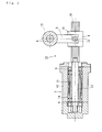
- Fig. 1 is a longitudinal sectional view showing a first embodiment of the ball screw actuator of the present invention;
- Fig. 2 is a longitudinal sectional view showing a second embodiment of the ball screw actuator of the present invention;
- Fig. 3 is a longitudinal sectional view showing an electric driving apparatus for transmission of vehicle of the prior art; and
- Fig. 4 is a longitudinal sectional view similar to Fig.3.
-
- Fig. 1 is a longitudinal sectional view showing a first embodiment of the ball screw actuator of the present invention. The
ball screw actuator 1 is used in the electric driving apparatus for transmission of vehicle and comprises a ball screw shaft 3 rotationally driven by anelectric motor 2 and aball screw nut 4 threadably engaged on the ball screw shaft 3 via balls (not shown). The shifting operation of the transmission is carried out by imparting the axial motion of theball screw nut 4 to the swing motion of adriving shaft 6 via a pair ofswing links - A motor shaft 7 of the
electric motor 2 is rotatably supported by a pair ofrolling bearings pins ball screw nut 4 threadably engaged on the ball screw shaft 3 via balls (not shown). The pair ofswing links ball screw nut 4 and eachswing link pin 10. Thus theball screw nut 4 is arranged so that it cannot rotate relative to the ball screw shaft 3 but can axially move therealong. The other ends of the shiftinglinks sleeve 12 and the drivingshaft 6 is fitted into the shiftingsleeve 12 via a serration (not shown) so that it can axially displace relative to the shiftingsleeve 12 and rotate therewith. - The
electric motor 2 comprises astator 14 secured on the inner circumferential surface of amotor housing 13, and arotor 15 fitted on the motor shaft 7 and opposed to thestator 14 via a predetermined air gap. When theelectric motor 2 is energized, the ball screw shaft 3 is rotated toward a predetermined direction and thus theball screw nut 4 is axially moved toward a predetermined direction. The axial movement of theball screw nut 4 is imparted to thedriving shaft 6 as its swing motion via theswing links - One of the pair of
rolling bearings bearing 8 arranged at a side opposite to the ball screw shaft 3 (i.e. the left-hand side in Fig. 1) is designed to have a inside gap smaller than that of the rollingbearing 9 arranged at a side near the ball screw shaft 3 (i.e. the right-hand side in Fig. 1) and adapted to support a thrust load. Such a design enables the pair ofrolling bearings electric motor 2 to support the radial load (moment load) and thrust load generated in the ball screw shaft 3, to prevent generation of slippage of the rolling bearings due to alternating load, and to suppress wear and heat generation of thebearings rolling bearings bearing 8 arranged at a side opposite to the ball screw shaft 3 (i.e. the left-hand side in Fig. 1) by the cylindrical roller bearing and the rollingbearing 9 arranged at a side near the ball screw shaft 3 (i.e. the right-hand side in Fig. 1) by the deep groove ball bearing, and vice versa. - In this first embodiment, since the ball screw shaft 3 has a cantilever structure in which one end thereof is freely released, it is possible to absorb the axial expansion due to its temperature rising without providing any expansion absorbing means. In addition, a housing for supporting the ball screw shaft 3 and rolling bearings such as used in the prior art are not necessary and thus it is possible to reduce the number of parts and to shorten the length of the ball screw shaft and thus to achieve reduction in size and weight of the actuator. Furthermore, simplification of assembly of the actuator in addition to the reduction of the number of parts can realize the low cost for manufacturing the actuator.
- Fig. 2 is a longitudinal sectional view showing a second embodiment of the ball screw actuator of the present invention. Same reference numerals used in the description of the first embodiment are used in the description of the second embodiment for designating the same parts.
- A
ball screw actuator 16 of this embodiment has a substantially same structure as that of the first embodiment and comprises theelectric motor 2, themotor shaft 17 inserted into theelectric motor 2, aball screw shaft 18 connected to themotor shaft 17 and rotationally driven by theelectric motor 2, aball screw nut 4 threadably engaged on theball screw shaft 18 via balls (not shown), and adriving shaft 6 to which the axial motion of theball screw nut 4 is imparted as the swing motion via aswing link 5 for carrying out the shifting operation of the transmission. - In contrast to the first embodiment in which the ball screw shaft 3 is integrally formed with the motor shaft 7, the
ball screw shaft 18 of this embodiment is formed as a separate part and press fitted co-axially to one end of themotor shaft 17 via a spigot joint. A motor shaft 7 of theelectric motor 2 is rotatably supported by a pair of rollingbearings motor shaft 17 and theball screw shaft 18 is not limited in the press fit connection and they may be detachably connected with each other by inserting one end of theball screw shaft 18 onto themotor shaft 17 and by radially inserting a connecting pin therethrough. - Similarly to the first embodiment, since the
ball screw shaft 18 is supported in the cantilever manner, it is possible to allow the axial expansion of theball screw shaft 18 due to temperature rising. In addition, a housing for supporting theball screw shaft 18 and rolling bearings such as used in the prior art are not necessary and thus it is possible to reduce the number of parts. Furthermore, when roll forming the ball screw shaft, the stroke range of the ball screw shaft is not limited by an incomplete screw portion (shown by "a" in Fig. 1) generated during the roll forming process and thus it is possible to shorten the whole length of the ball screw shaft. Accordingly, it is possible to further reduce the size and weight of the actuator. - The ball screw actuator of the present invention can be applied not only to the electric driving apparatus for transmission of a vehicle, but to any driving mechanism especially to an electric actuator for a driving mechanism requiring a high reduction ratio.
- The present invention has been described with reference to the preferred embodiment. Obviously, modifications and alternations will occur to those of ordinary skill in the art upon reading and understanding the preceding detailed description. It is intended that the present invention be construed as including all such alternations and modifications insofar as they come within the scope of the appended claims or the equivalents thereof.
Claims (6)
- A ball screw actuator comprising an electric motor (2), a motor shaft (7 or 17) through-fitted in the electric motor (2), a ball screw shaft (3 or 18) rotationally driven by the electric motor (2), a ball screw nut (4) threadably engaged on the ball screw shaft (3 or 18) via balls and provided with a pair of pins (10) oppositely projected from the outer circumferential surface of the ball screw nut (4), and a driving shaft (6) to which the axial motion of the ball screw nut (4) is imparted as the swing motion via a swing link (5) engaging the pins (10) CHARACTERIZED in that the ball screw shaft (3 or 18) is connected to one end of the motor shaft (7 or 17), and in that the ball screw shaft (3 or 18) is rotatably supported in the cantilever manner by a pair of rolling bearings (8 and 9) self-contained within the electric motor (2).
- A ball screw actuator of claim 1 wherein one of the pair of rolling bearings (8 or 9) supports the thrust load.
- A ball screw actuator of claim 2 wherein one of the pair of rolling bearings (8 or 9) has an inside gap smaller than that of the other rolling bearing (9 or 8).
- A ball screw actuator of claim 2 wherein one of the pair of rolling bearings (8 or 9) is a cylindrical roller bearing and the other of the rolling bearing (9 or 8) is a deep groove ball bearing.
- A ball screw actuator any one of claims 1 through 4 wherein the ball screw shaft (3) is integrally formed with one end of the motor shaft (7).
- A ball screw actuator any one of claims 1 through 4 wherein the ball screw shaft (18) is connected to one end of the motor shaft (17) via a spigot joint.
Applications Claiming Priority (2)
| Application Number | Priority Date | Filing Date | Title |
|---|---|---|---|
| JP2003412839A JP4514021B2 (en) | 2003-12-11 | 2003-12-11 | Ball screw actuator |
| JP2003412839 | 2003-12-11 |
Publications (2)
| Publication Number | Publication Date |
|---|---|
| EP1541904A1 true EP1541904A1 (en) | 2005-06-15 |
| EP1541904B1 EP1541904B1 (en) | 2008-02-13 |
Family
ID=34510536
Family Applications (1)
| Application Number | Title | Priority Date | Filing Date |
|---|---|---|---|
| EP20040028824 Expired - Fee Related EP1541904B1 (en) | 2003-12-11 | 2004-12-04 | A ball screw actuator |
Country Status (3)
| Country | Link |
|---|---|
| EP (1) | EP1541904B1 (en) |
| JP (1) | JP4514021B2 (en) |
| DE (1) | DE602004011738T2 (en) |
Cited By (3)
| Publication number | Priority date | Publication date | Assignee | Title |
|---|---|---|---|---|
| CN107524771A (en) * | 2016-06-22 | 2017-12-29 | 致茂电子(苏州)有限公司 | Swing mechanism |
| CN109915567A (en) * | 2019-03-27 | 2019-06-21 | 南京理工大学 | A kind of multistage synchronous lead screw transfer bar mechanism |
| US11703124B2 (en) | 2019-12-09 | 2023-07-18 | Ningbo Geely Automobile Research & Development Co. | Actuator system for a vehicle transmission, a vehicle comprising an actuator system, and a method for operating an actuator system |
Families Citing this family (4)
| Publication number | Priority date | Publication date | Assignee | Title |
|---|---|---|---|---|
| DE102005039559B4 (en) * | 2005-08-22 | 2020-03-05 | Knorr-Bremse Systeme für Nutzfahrzeuge GmbH | Electromechanical transmission control |
| JP5983040B2 (en) * | 2012-05-30 | 2016-08-31 | 日本精工株式会社 | Actuator |
| DE102014218090B3 (en) * | 2014-09-10 | 2016-02-18 | Schaeffler Technologies AG & Co. KG | Clutch actuator and clutch unit |
| DE102014218091B3 (en) * | 2014-09-10 | 2016-02-18 | Schaeffler Technologies AG & Co. KG | Clutch actuator and clutch unit |
Citations (5)
| Publication number | Priority date | Publication date | Assignee | Title |
|---|---|---|---|---|
| GB2000844A (en) * | 1977-07-07 | 1979-01-17 | Roltra Spa | Screw-nut screw transmission coupling |
| US5255882A (en) * | 1990-06-19 | 1993-10-26 | Diehl Gmbh & Co. | Setting device with a nut controllable by a spindle |
| EP0647503A2 (en) * | 1993-10-12 | 1995-04-12 | Smc Kabushiki Kaisha | Linear guiding device and system |
| US5784922A (en) * | 1994-08-06 | 1998-07-28 | Kabushiki Kaisha Toyoda Jidoshokki Seisakusho | Motor for converting rotation of a shaft to linear movement |
| JP2002317871A (en) * | 2001-04-19 | 2002-10-31 | Nsk Ltd | Electric driving device for transmission |
Family Cites Families (5)
| Publication number | Priority date | Publication date | Assignee | Title |
|---|---|---|---|---|
| JPS60155051A (en) * | 1984-01-25 | 1985-08-14 | Matsushita Electric Ind Co Ltd | Electrically-driven rectilinear motion actuator |
| JP2580317B2 (en) * | 1989-02-16 | 1997-02-12 | 三菱重工業株式会社 | Synchronous steering system for multiple steering bodies |
| JPH07133855A (en) * | 1993-11-10 | 1995-05-23 | Smc Corp | Actuator |
| JP2000107865A (en) * | 1998-10-01 | 2000-04-18 | Obara Corp | Motor incorporated type driving unit in motor-driven welding machine |
| JP2002174325A (en) * | 2000-12-04 | 2002-06-21 | Nissan Motor Co Ltd | Idler gear support structure |
-
2003
- 2003-12-11 JP JP2003412839A patent/JP4514021B2/en not_active Expired - Fee Related
-
2004
- 2004-12-04 EP EP20040028824 patent/EP1541904B1/en not_active Expired - Fee Related
- 2004-12-04 DE DE200460011738 patent/DE602004011738T2/en active Active
Patent Citations (5)
| Publication number | Priority date | Publication date | Assignee | Title |
|---|---|---|---|---|
| GB2000844A (en) * | 1977-07-07 | 1979-01-17 | Roltra Spa | Screw-nut screw transmission coupling |
| US5255882A (en) * | 1990-06-19 | 1993-10-26 | Diehl Gmbh & Co. | Setting device with a nut controllable by a spindle |
| EP0647503A2 (en) * | 1993-10-12 | 1995-04-12 | Smc Kabushiki Kaisha | Linear guiding device and system |
| US5784922A (en) * | 1994-08-06 | 1998-07-28 | Kabushiki Kaisha Toyoda Jidoshokki Seisakusho | Motor for converting rotation of a shaft to linear movement |
| JP2002317871A (en) * | 2001-04-19 | 2002-10-31 | Nsk Ltd | Electric driving device for transmission |
Non-Patent Citations (1)
| Title |
|---|
| PATENT ABSTRACTS OF JAPAN vol. 2003, no. 02 5 February 2003 (2003-02-05) * |
Cited By (3)
| Publication number | Priority date | Publication date | Assignee | Title |
|---|---|---|---|---|
| CN107524771A (en) * | 2016-06-22 | 2017-12-29 | 致茂电子(苏州)有限公司 | Swing mechanism |
| CN109915567A (en) * | 2019-03-27 | 2019-06-21 | 南京理工大学 | A kind of multistage synchronous lead screw transfer bar mechanism |
| US11703124B2 (en) | 2019-12-09 | 2023-07-18 | Ningbo Geely Automobile Research & Development Co. | Actuator system for a vehicle transmission, a vehicle comprising an actuator system, and a method for operating an actuator system |
Also Published As
| Publication number | Publication date |
|---|---|
| DE602004011738D1 (en) | 2008-03-27 |
| JP2005172127A (en) | 2005-06-30 |
| JP4514021B2 (en) | 2010-07-28 |
| DE602004011738T2 (en) | 2009-02-05 |
| EP1541904B1 (en) | 2008-02-13 |
Similar Documents
| Publication | Publication Date | Title |
|---|---|---|
| US7556581B2 (en) | Transmission having integrated braking device | |
| JP4790608B2 (en) | Double clutch transmission | |
| CN100470095C (en) | Forward-reverse switching device for stepless speed changer | |
| KR950008236Y1 (en) | Charge speed mechanism for a motor driving tool | |
| WO2015068821A1 (en) | Power transmission device | |
| US8727931B2 (en) | Gear train unit and arrangement for a stamping press | |
| US6988831B2 (en) | Bearing structure | |
| KR101546555B1 (en) | Arrangement for shifting at least two freewheels | |
| EP1541904B1 (en) | A ball screw actuator | |
| CN102084153A (en) | Transmission, in particular dual-clutch transmission | |
| JP2013044406A (en) | Electric transmission and drive device for electric vehicle | |
| JP5606538B2 (en) | Uncouple drive mechanism | |
| US6413186B1 (en) | Power train system for a vehicle | |
| US20180320769A1 (en) | Bearing arrangement for a stepped planetary gear, and epicyclic gearing equipped therewith for a motor vehicle drive unit | |
| US6960151B2 (en) | Toroidal continuously variable transmission | |
| JP2004249987A (en) | Power splitter with adjustable clutch | |
| KR102519194B1 (en) | Limited slip differential for vehicles and electric drive apparatus including same | |
| KR102519195B1 (en) | Limited slip differential for vehicles and electric drive apparatus including same | |
| US7648011B2 (en) | Compact drive assembly with multi-plate coupling | |
| JP2527399Y2 (en) | Suspension of torque converter | |
| KR20200114879A (en) | Driving apparatus for electric vehicle | |
| US20150352951A1 (en) | Combined Power Take-Off and Synchronizer Assembly | |
| JP4599994B2 (en) | Planetary gear device for vehicle power transmission device | |
| JP4072531B2 (en) | Power split type continuously variable transmission | |
| JP4158320B2 (en) | Continuously variable transmission |
Legal Events
| Date | Code | Title | Description |
|---|---|---|---|
| PUAI | Public reference made under article 153(3) epc to a published international application that has entered the european phase |
Free format text: ORIGINAL CODE: 0009012 |
|
| AK | Designated contracting states |
Kind code of ref document: A1 Designated state(s): AT BE BG CH CY CZ DE DK EE ES FI FR GB GR HU IE IS IT LI LT LU MC NL PL PT RO SE SI SK TR |
|
| AX | Request for extension of the european patent |
Extension state: AL BA HR LV MK YU |
|
| 17P | Request for examination filed |
Effective date: 20051122 |
|
| AKX | Designation fees paid |
Designated state(s): DE FR IT |
|
| GRAP | Despatch of communication of intention to grant a patent |
Free format text: ORIGINAL CODE: EPIDOSNIGR1 |
|
| GRAS | Grant fee paid |
Free format text: ORIGINAL CODE: EPIDOSNIGR3 |
|
| GRAA | (expected) grant |
Free format text: ORIGINAL CODE: 0009210 |
|
| AK | Designated contracting states |
Kind code of ref document: B1 Designated state(s): DE FR IT |
|
| REF | Corresponds to: |
Ref document number: 602004011738 Country of ref document: DE Date of ref document: 20080327 Kind code of ref document: P |
|
| ET | Fr: translation filed | ||
| PLBE | No opposition filed within time limit |
Free format text: ORIGINAL CODE: 0009261 |
|
| STAA | Information on the status of an ep patent application or granted ep patent |
Free format text: STATUS: NO OPPOSITION FILED WITHIN TIME LIMIT |
|
| 26N | No opposition filed |
Effective date: 20081114 |
|
| PG25 | Lapsed in a contracting state [announced via postgrant information from national office to epo] |
Ref country code: IT Free format text: LAPSE BECAUSE OF FAILURE TO SUBMIT A TRANSLATION OF THE DESCRIPTION OR TO PAY THE FEE WITHIN THE PRESCRIBED TIME-LIMIT Effective date: 20080213 |
|
| REG | Reference to a national code |
Ref country code: FR Ref legal event code: PLFP Year of fee payment: 12 |
|
| REG | Reference to a national code |
Ref country code: FR Ref legal event code: PLFP Year of fee payment: 13 |
|
| PGFP | Annual fee paid to national office [announced via postgrant information from national office to epo] |
Ref country code: FR Payment date: 20161111 Year of fee payment: 13 Ref country code: DE Payment date: 20161129 Year of fee payment: 13 |
|
| REG | Reference to a national code |
Ref country code: DE Ref legal event code: R119 Ref document number: 602004011738 Country of ref document: DE |
|
| REG | Reference to a national code |
Ref country code: FR Ref legal event code: ST Effective date: 20180831 |
|
| PG25 | Lapsed in a contracting state [announced via postgrant information from national office to epo] |
Ref country code: DE Free format text: LAPSE BECAUSE OF NON-PAYMENT OF DUE FEES Effective date: 20180703 Ref country code: FR Free format text: LAPSE BECAUSE OF NON-PAYMENT OF DUE FEES Effective date: 20180102 |