EP1541850A1 - Device to adapt the nozzle of a rocket motor with thrust vectoring control - Google Patents
Device to adapt the nozzle of a rocket motor with thrust vectoring control Download PDFInfo
- Publication number
- EP1541850A1 EP1541850A1 EP04292880A EP04292880A EP1541850A1 EP 1541850 A1 EP1541850 A1 EP 1541850A1 EP 04292880 A EP04292880 A EP 04292880A EP 04292880 A EP04292880 A EP 04292880A EP 1541850 A1 EP1541850 A1 EP 1541850A1
- Authority
- EP
- European Patent Office
- Prior art keywords
- divergent
- nozzle
- jet
- diverging
- diverging portion
- Prior art date
- Legal status (The legal status is an assumption and is not a legal conclusion. Google has not performed a legal analysis and makes no representation as to the accuracy of the status listed.)
- Granted
Links
- 239000000567 combustion gas Substances 0.000 claims abstract description 12
- 230000006978 adaptation Effects 0.000 claims description 13
- 239000007789 gas Substances 0.000 claims description 11
- 210000003462 vein Anatomy 0.000 claims description 11
- 239000000463 material Substances 0.000 claims description 10
- 238000000926 separation method Methods 0.000 claims description 10
- 239000002131 composite material Substances 0.000 claims description 8
- 229910052751 metal Inorganic materials 0.000 claims description 5
- 239000002184 metal Substances 0.000 claims description 5
- 229920005989 resin Polymers 0.000 claims description 5
- 239000011347 resin Substances 0.000 claims description 5
- 239000000835 fiber Substances 0.000 claims description 4
- 229920001971 elastomer Polymers 0.000 claims description 3
- 239000000806 elastomer Substances 0.000 claims description 3
- 238000002485 combustion reaction Methods 0.000 description 5
- 230000007423 decrease Effects 0.000 description 5
- OKTJSMMVPCPJKN-UHFFFAOYSA-N Carbon Chemical compound [C] OKTJSMMVPCPJKN-UHFFFAOYSA-N 0.000 description 4
- 229910052799 carbon Inorganic materials 0.000 description 4
- 230000000694 effects Effects 0.000 description 4
- 230000008034 disappearance Effects 0.000 description 3
- 238000005516 engineering process Methods 0.000 description 3
- 239000003292 glue Substances 0.000 description 3
- 230000000750 progressive effect Effects 0.000 description 3
- 230000001141 propulsive effect Effects 0.000 description 3
- 238000011144 upstream manufacturing Methods 0.000 description 3
- VYPSYNLAJGMNEJ-UHFFFAOYSA-N Silicium dioxide Chemical compound O=[Si]=O VYPSYNLAJGMNEJ-UHFFFAOYSA-N 0.000 description 2
- 238000007654 immersion Methods 0.000 description 2
- 239000007788 liquid Substances 0.000 description 2
- 239000011159 matrix material Substances 0.000 description 2
- HBMJWWWQQXIZIP-UHFFFAOYSA-N silicon carbide Chemical compound [Si+]#[C-] HBMJWWWQQXIZIP-UHFFFAOYSA-N 0.000 description 2
- 229910010271 silicon carbide Inorganic materials 0.000 description 2
- KXGFMDJXCMQABM-UHFFFAOYSA-N 2-methoxy-6-methylphenol Chemical compound [CH]OC1=CC=CC([CH])=C1O KXGFMDJXCMQABM-UHFFFAOYSA-N 0.000 description 1
- 239000004593 Epoxy Substances 0.000 description 1
- 239000004698 Polyethylene Substances 0.000 description 1
- 239000000853 adhesive Substances 0.000 description 1
- 230000001070 adhesive effect Effects 0.000 description 1
- 229910052782 aluminium Inorganic materials 0.000 description 1
- XAGFODPZIPBFFR-UHFFFAOYSA-N aluminium Chemical compound [Al] XAGFODPZIPBFFR-UHFFFAOYSA-N 0.000 description 1
- 230000003321 amplification Effects 0.000 description 1
- 239000004760 aramid Substances 0.000 description 1
- 229920003235 aromatic polyamide Polymers 0.000 description 1
- 230000015556 catabolic process Effects 0.000 description 1
- 210000003679 cervix uteri Anatomy 0.000 description 1
- 239000000470 constituent Substances 0.000 description 1
- 238000006073 displacement reaction Methods 0.000 description 1
- 230000008030 elimination Effects 0.000 description 1
- 238000003379 elimination reaction Methods 0.000 description 1
- 239000002360 explosive Substances 0.000 description 1
- 238000010304 firing Methods 0.000 description 1
- 239000012530 fluid Substances 0.000 description 1
- 239000011521 glass Substances 0.000 description 1
- 230000001939 inductive effect Effects 0.000 description 1
- 239000011810 insulating material Substances 0.000 description 1
- 238000004519 manufacturing process Methods 0.000 description 1
- 238000000034 method Methods 0.000 description 1
- 230000004048 modification Effects 0.000 description 1
- 238000012986 modification Methods 0.000 description 1
- 238000003199 nucleic acid amplification method Methods 0.000 description 1
- 230000000149 penetrating effect Effects 0.000 description 1
- ISWSIDIOOBJBQZ-UHFFFAOYSA-N phenol group Chemical group C1(=CC=CC=C1)O ISWSIDIOOBJBQZ-UHFFFAOYSA-N 0.000 description 1
- 229920001568 phenolic resin Polymers 0.000 description 1
- 239000005011 phenolic resin Substances 0.000 description 1
- -1 polyethylene Polymers 0.000 description 1
- 229920000573 polyethylene Polymers 0.000 description 1
- 239000003380 propellant Substances 0.000 description 1
- 230000002787 reinforcement Effects 0.000 description 1
- 239000000377 silicon dioxide Substances 0.000 description 1
- 239000004449 solid propellant Substances 0.000 description 1
- 239000007921 spray Substances 0.000 description 1
Images


Classifications
-
- F—MECHANICAL ENGINEERING; LIGHTING; HEATING; WEAPONS; BLASTING
- F02—COMBUSTION ENGINES; HOT-GAS OR COMBUSTION-PRODUCT ENGINE PLANTS
- F02K—JET-PROPULSION PLANTS
- F02K9/00—Rocket-engine plants, i.e. plants carrying both fuel and oxidant therefor; Control thereof
- F02K9/80—Rocket-engine plants, i.e. plants carrying both fuel and oxidant therefor; Control thereof characterised by thrust or thrust vector control
- F02K9/84—Rocket-engine plants, i.e. plants carrying both fuel and oxidant therefor; Control thereof characterised by thrust or thrust vector control using movable nozzles
-
- F—MECHANICAL ENGINEERING; LIGHTING; HEATING; WEAPONS; BLASTING
- F02—COMBUSTION ENGINES; HOT-GAS OR COMBUSTION-PRODUCT ENGINE PLANTS
- F02K—JET-PROPULSION PLANTS
- F02K9/00—Rocket-engine plants, i.e. plants carrying both fuel and oxidant therefor; Control thereof
- F02K9/97—Rocket nozzles
- F02K9/978—Closures for nozzles; Nozzles comprising ejectable or discardable elements
Definitions
- the present invention relates to steerable nozzles for rocket engines.
- the field of application of the invention is more particularly, but not exclusively, that of missiles, in particular tactical missiles with a diameter of less than approximately 500 mm and which are intended to operate under conditions of external pressure variables.
- a typical example of these machines is that of the tactical missile fired by a submarine.
- the missile is lit at great depth (approximately 150m) and ends its operational life in the atmospheric phase after have done through the steering of the nozzle or nozzles a trajectory determined.
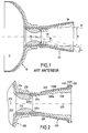
- FIG. 1 illustrates very schematically a rocket engine equipped with a diverging nozzle mobile.
- the rocket engine comprises an envelope 10 surrounding a combustion chamber 11 which opens into a nozzle.
- the nozzle 20 is formed of a neck 12 receiving the hot gases produced in the chamber of combustion and a divergent 20.
- the diverging 20 is mounted so mobile on the neck 12 which is secured to the bottom of the envelope 10.
- the divergent is the only moving part of the nozzle that allows by its pivoting to deflect the jet of combustion gases from the neck so to orient the trajectory of the thruster by changing the direction of the vector thrust.
- the diameter D of jet 32 of the nozzle narrows resulting in the detachment of the jet from the divergent wall as illustrated in FIG.
- nozzles are generally optimized for depending on the overall performance of the launcher.
- we define a expansion profile i.e. section variation in the nozzle depending from a certain altitude, called “adaptation" altitude, above which is the majority of the flight. Below this altitude, the nozzle is over-relaxed and the high external pressure can cause the detachment of the jet of the divergent wall.
- the detachment of the jet inside the nozzle can induce instabilities creating harmful vibratory stresses mechanically.
- the problem of reducing the pilotability due to the detachment of jet in the diverging is particularly noticeable in the nozzles at divergent mobile because it is the forces applied to the inner wall of the divergent that can direct the craft during his flight.
- the other directional nozzle systems such as thrust nozzles flexible, it is the whole vein of the nozzle that moves.
- the jet of gas ejected from the combustion chamber is deflected directly to the outlet of the col since the axis of the latter is displaced with that of the divergent.
- the orientation of the pushed vector is therefore at the level of the cervix of nozzle, that is to say upstream of the divergent, the detachment of the jet in the divergent then having practically no influence on the controllability of the nozzle.
- the present invention aims to provide a solution to the problem posed by jet separation in a divergent nozzle mobile in order to remove or reduce its influence on the flyability of the nozzle.
- this goal is achieved through an adaptation structure that is disposed within the diverging portion of the nozzle so as to reduce the divergent character of the vein of it and to increase the area application of the pressure forces exerted by the jet on the divergent when turning it.
- This structure makes it possible to fill the space between the inner wall of the divergent and the jet during its detachment to maintain contact, via said structure, between the jet and the divergent.
- it is possible to establish an asymmetrical pressure field in the divergent when turning it.
- the capabilities of thrust deviation of a movable divergent nozzle are not affected by an increase in external pressure.
- the shape, dimensions and layout of the structure adaptation are preferably chosen so as to optimize the efficiency in steering as well as the impact on the propulsive performance of the engine.
- the structure may for example be of axisymmetrical shape of revolution or have fin-shaped protuberances arranged uniformly on the structure in the vicinity of the section of exit of the diverging gases. Thus, even in the presence of a detachment of jet this one can be "hooked" by fins.
- the structure may be present for the duration of the flight or disappear at a given moment to find the normal configuration divergent. In the latter case, the structure is fixed to the divergent by connecting means with associated means, for example pyrotechnics, to control the breakdown of the means of link a determined time after firing.
- the structure can be made of a metal, a resin reinforced with elastomer fibers or a thermostructural composite material.
- the structure can also be erased gradually so to optimize the relaxation in the divergent according to a decrease, also progressive, external pressure.
- the problem of the influence of jet detachment on thrust deflection capabilities in a movable divergent nozzle can be solved by setting up of an annular piece at the end of the divergent at the section of gas outlet, the part having portions projecting inwards from the diverging so as to form, during the turning of the divergent, a surface for the application of the pressure forces exerted by the jet.
- the latter can be "hooked" by parts of the annular piece which is in solidarity with the divergent. This allows the jet to exert more force important on the steering divergence and, therefore, compensate for the decrease in the pressure forces applied to the wall of the diverge in case of jet separation.
- the shape, number and dimensions of the projecting parts of the annular part are preferably defined according to the level of the compensation force that one wishes to obtain during the detachment of the jet of the inner wall of the divergent.
- the annular piece can be attached to the divergent by connecting means permanent or by fastening systems whose break may be ordered at a given moment.
- the piece can be made in one material having an ephemeral behavior to the combustion gases so as to gradually disappear in contact with them.
- the invention also relates to a movable divergent nozzle equipped with one of the adaptation devices described above.
- Figure 2 illustrates very schematically the rear part of a rocket engine comprising an envelope 210 surrounding a chamber of combustion 211 in which is housed a block of solid propellant (no represent).
- the chamber 211 opens through its rear bottom 213 to the front of a nozzle comprising a neck 212 and a divergent 220.
- the collar 212 which not only defines the nozzle neck neatly said but also converge and a primer of divergent, is fixed by example by screwing into a ring 214 fixed to the bottom 213 of the envelope, so as to be secured to the bottom 213.
- the nozzle divergent 220 is movably mounted on the neck 212 nozzle which is integral with the casing 210.
- the movable divergent typically comprises an envelope 221 which may be for example metal having an inner layer 223 of insulating material such as a ablative composite for example composed of carbon or silica reinforcement and a phenolic resin matrix.
- the divergent mobile 220 comprises a piece 224 in the form of an inner ring made typically thermostructural composite material.
- Col 212 and the moving divergent 220 are in mutual contact by spherical surfaces respective 212a, 224a centered on the axis 215 of the nozzle.
- the divergent 220 is then movable on the neck 212 in several directions. So in steering the divergent, the thrust is oriented according to the angle formed between the axis 225 of the divergent and the axis 215 of the nozzle.
- the mobile nozzle divergent is connected to the fixed part thereof by via a mechanical link (not shown) comprising actuating means (eg cylinders) which make it possible to control the steering of the divergent.
- actuating means eg cylinders
- This type of assembly forming a nozzle to divergent mobile is well known per se and will not be described in more detail.
- An exemplary embodiment of such a nozzle is described in particular in the French patent application FR 02 08370.
- the movable diverging nozzle is advantageous in that that it can amplify the thrust deviation depending on the angle effective pivoting of the main axis of the divergent.
- this thrust deflection ability decreases significantly in the presence of a jet detachment. Indeed, when there is a space between the jet and the inner wall of the divergent illustrated in Figure 1, the impact of the jet on the divergent is very limited in because of its small contact surface with the divergent. More precisely, in the presence of a jet detachment in the divergent, the influence of divergent steering on the orientation of the thrust vector remains limited as long as the deflection remains within an angular range that does not allows the jet to substantially re-glue the inner wall of the diverging.
- a structure 230 is introduced into the divergent 220 of the nozzle.
- This structure 230 reduces the vein of the divergent to prevent the detachment of the jet when the external pressure is such that it would lead normally to jet detachment in the absence of such a structure.
- the shape and dimensions of the structure 230 can be very varied depending on the profile of the vein that one wishes to obtain in particular for optimize steering efficiency.
- the structure 230 presents preferably an external form 230b close to that of the moving part of the divergent where it should be arranged and an internal form 230a which maintains a substantially divergent structure to ensure good expansion of the combustion gases.
- the thickness of the structure 230 will be determined so as to fill the space between the jet and the inner wall divergent when detaching the jet. This thickness is preferably determined to fill the maximum space that can exist between the jet and the divergent during the detachment. The maximum detachment appears at the highest external pressure encountered during the flight. As example, for a missile intended to be launched in immersion, the thickness of structure 230 will be calculated to fill the space present at the depth of fire that corresponds to the highest external pressure during the flight phase.
- the structure 230 may be attached to the divergent by means of fastening 232 such as bolt members for example.
- structure 230 comprises a flange 231 which cooperates with a flange 2231 of the internal protection 223 of the divergent.
- the flange 231 may be attached to a flange of the envelope 221 of the diverge.
- the structure 230 may be present throughout the duration of the flight or else disappear at a specific moment from which the capabilities in natural turning of the divergent mobile are compatible with the needs in control of the machine in particular in order to optimize the performances propulsive engine. If the adaptation device is kept during the entire duration of the flight, the structure 230 and the internal protection 23 can constitute only one element.
- the fasteners 232 may be equipped with a system pyrotechnic explosive bolts or a cutting line end of the diverging or any other mechanical system for order the expulsion of the structure at a given moment.
- the structure 230 may consist of a material ablatable allowing a progressive disappearance of the structure. In the case of a missile launched in immersion for example, it allows to have a vein profile that expands as external pressure increases decreases, thus optimizing the expansion of the gases and, consequently, the propulsive performance during the flight.
- the progressive modification of the vein during the mission can also be obtained with a structure composed of several subassemblies nested in each other and releasable successively to determined moments of the mission.
- each subset may be attached to the neighboring or diverging subset by link whose break can be ordered.
- FIGS. 3A and 3B is distinguished particular of that of FIG. 2 in that the internal structure disposed inside the divergent has a non-axisymmetric shape in its downstream part.
- the structure 330 includes in its downstream part of the protuberances 333 protruding into the vein of the nozzle in the vicinity of the divergent outlet.
- protuberances 333 are profiled in the form of fins and distributed evenly around the axis of the structure 330.
- the protuberances 333 thus form obstacles for the jet inside the divergent. it allows the jet to always be in contact with a solidarity element of diverge and, therefore, allow for thrust deviation effective even in the presence of a jet detachment.
- the structure 330 is held inside the diverging part by fixing members 332 of type bolts inserted in holes drilled on the flange 331 of the structure, on the one hand, and on a flange 3211 of the outer envelope 321 of the divergent on the other hand.
- the structure 330 is here fixed by through a flange 3211, on the outer casing 321 of the diverge rather than its internal protection as shown in Figure 2.
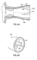
- FIGS. 4A and 4B illustrate another embodiment variant of FIG. structure allowing to hang the jet in the divergent according to the invention.
- the structure 430 has three protuberances 433 distributed evenly in the downstream part of the structure 430.
- structure 430 differs of that shown in FIGS. 3A and 3B in that it is fixed by bonding by means of a layer of adhesive 434 deposited on the protection internal 430 divergent 420.
- the structure of the set is Simplified since it does not form a fastening flange on the structure spray hook and on the envelope of the diverging or its protection internal.
- the bonded bond can be reinforced if necessary by pieces (not shown) perpendicular to the axis of the nozzle and penetrating into the structure without opening into the flow vein.
- the Structure 430 is advantageously made of ablatable material.
- the pilotability problem of the nozzle in case of jet detachment can be also solved with devices that are arranged not inside the divergent but at the exit of it.
- divergent 520 can be adapted with an annular piece 530 which is attached to the end of the divergent 520 at the exit section of the gases.
- the annular part 530 comprises projections 533 which extend inwardly of the divergent.
- the projections are used as additional areas of application for pressure exerted by the jet of ejected combustion gases. Indeed, when diverge in one direction, the jet will hit one or more of these projections on a more or less important surface according to the angle of steering applied.
- the geometry of the annular piece (shape, number and arrangement of projections, ...) can be very varied. It is mainly defined in according to the needs in terms of thrust deviation.
- the annular piece may be present during the entire phase of flight or disappear at a given moment.
- the room can therefore be attached to the diverging part by means of possibly equipped connecting means to control the expulsion of the structure at a time determined.
- the annular piece may consist of a ablatable material allowing a gradual disappearance of the structure during flight.
- the choice of the constituent material is varied. It depends in particular the gases and temperatures encountered and the method of elimination selected. It can be metallic, composite organic matrix consisting of fibers of glass, aramid, polyethylene or other and of resin such epoxy, phenolic or even elastomeric or thermostructural composite material such as carbon / carbon (C / C) or carbon / silicon carbide (C / SiC).
- a material that sublimates under the effect of hot gases such as a composite material of the fiberglass-reinforced resin type or a easily sublimable metal, such as aluminum.
Abstract
Description
La présente invention se rapporte aux tuyères orientables pour moteurs fusées. Le domaine d'application de l'invention est plus particulièrement, mais non exclusivement celui des missiles, notamment de missiles tactiques dont le diamètre est inférieur à environ 500 mm et qui sont destinés à fonctionner dans des conditions de pression externe variables. Un exemple typique de ces engins est celui du missile tactique tiré par un sous marin. Le missile est allumé à grande profondeur (environ 150m) et termine sa vie opérationnelle en phase atmosphérique après avoir effectué grâce au pilotage de la ou des tuyères une trajectoire déterminée.The present invention relates to steerable nozzles for rocket engines. The field of application of the invention is more particularly, but not exclusively, that of missiles, in particular tactical missiles with a diameter of less than approximately 500 mm and which are intended to operate under conditions of external pressure variables. A typical example of these machines is that of the tactical missile fired by a submarine. The missile is lit at great depth (approximately 150m) and ends its operational life in the atmospheric phase after have done through the steering of the nozzle or nozzles a trajectory determined.
La technologie utilisant un divergent mobile pour orienter la poussée présente de nombreux avantages par rapport aux autres technologies connues d'orientation de poussée telles que celles utilisant une tuyère orientable sur butée flexible, par exemple. En effet, les tuyères où seul le divergent est mobile présentent des capacités de déviation de poussée nettement supérieures à celles que l'on peut obtenir avec les tuyères orientables dans lesquelles toute la veine de tuyère est mobile. Cette amélioration de la déviation de poussée s'explique par la présence, dans la zone mobile du divergent et en configuration braquée, d'un champ de pression dissymétrique qui conduit à un coefficient d'amplification supérieur à 1 par rapport au seul effet géométrique. Cette technologie ainsi que ses avantages par rapport aux autres types de tuyères orientables sont décrits notamment dans la demande de brevet français FR 02 08370.Technology using a mobile divergent to guide the thrust has many advantages over others known thrust orientation technologies such as those using a steerable nozzle on flexible abutment, for example. Indeed, the nozzles where only the divergent is mobile have deviation capabilities of significantly higher than that which can be achieved with steerable nozzles in which the entire nozzle stream is movable. This improvement of the thrust deviation is explained by the presence, in the moving zone of the divergent and in the pointed configuration, of a field of asymmetrical pressure which leads to an amplification coefficient greater than 1 in relation to the single geometric effect. This technology as well as its advantages over other types of nozzles orientable are described in particular in the French patent application FR 02 08370.
Cependant, une telle pilotabilité ne peut être obtenue que dans l'hypothèse d'une non perturbation de l'écoulement dans la veine de la tuyère, la perturbation étant liée à la pression externe et à la nature même du milieu (liquide ou gazeux). Or, compte tenu des niveaux de pression de combustion générés aujourd'hui dans les propulseurs et du profil de détente adapté pour optimiser la poussée de celui-ci sur toute la durée de sa mission, des décollements de jet dans la zone "active" de déviation de poussée du divergent peuvent se produire en présence d'une pression externe élevée. However, such controllability can only be achieved in the hypothesis of a non disturbance of the flow in the vein of the nozzle, the perturbation being related to the external pressure and the nature even medium (liquid or gaseous). However, given the levels of combustion pressures generated today in propellants and relaxation profile adapted to optimize the thrust of it all over the duration of its mission, jet detachments in the "active" zone of deviation of thrust from the divergent can occur in the presence of a high external pressure.
Ce phénomène est illustré sur la figure 1 qui illustre très
schématiquement un moteur fusée équipé d'une tuyère à divergent
mobile. Le moteur fusée comprend une enveloppe 10 entourant une
chambre de combustion 11 qui débouche dans une tuyère. La tuyère 20
est formée d'un col 12 recevant les gaz chauds produits dans la chambre
de combustion et d'un divergent 20. Le divergent 20 est monté de façon
mobile sur le col 12 qui est solidaire du fond de l'enveloppe 10. Ainsi, le
divergent est la seule partie mobile de la tuyère qui permet par son
pivotement de dévier le jet des gaz de combustion issus du col afin
d'orienter la trajectoire du propulseur en changeant la direction du vecteur
de poussée.This phenomenon is illustrated in Figure 1 which illustrates very
schematically a rocket engine equipped with a diverging nozzle
mobile. The rocket engine comprises an
Dans des conditions de pression externe élevée tel qu'en milieu
sous-marin, le diamètre D du jet 32 de la tuyère rétrécit entraínant le
décollement du jet de la paroi du divergent comme illustré sur la figure 1.
Cela vient du fait que les tuyères sont généralement optimisées en
fonction des performances globales du lanceur. A cet effet, on définit un
profil de détente (i.e. variation de section dans la tuyère) en fonction
d'une certaine altitude, dite altitude "d'adaptation", au dessus de laquelle
se situe la majorité du vol. En dessous de cette altitude, la tuyère est sur-détendue
et la pression externe élevée peut provoquer le décollement du
jet de la paroi du divergent.In conditions of high external pressure such as in the middle
underwater, the diameter D of
Lorsque le jet se décolle de la paroi du divergent, il se forme une
zone perturbée 30 qui s'étend du point de décollement du jet jusqu'à
l'extrémité du divergent et dans laquelle remonte le fluide externe qui
peut être, suivant le milieu, liquide ou gazeux. La zone d'application 31
des efforts de pression induisant en braquage l'effort latéral qui permet
d'orienter la trajectoire de l'engin et qui s'étend habituellement sur toute
la surface interne du divergent, se trouve cantonnée dans la partie amont
du divergent, c'est-à-dire entre la sortie du col et le point de décollement
du jet dans le divergent. La dissymétrie du champ de pression à l'intérieur
du divergent est considérablement réduite, ce qui entraíne une diminution
de l'effort latéral qui permet de diriger l'engin. L'influence de l'effort latéral
sur l'orientation de l'engin est d'autant plus limitée que sa zone
d'application se trouve à proximité du point d'appui du divergent sur le col
(effet levier réduit). Ainsi, tant que le jet est décollé de la paroi du
divergent, la pilotabilité de la tuyère reste très limitée. When the jet comes off the wall of the divergent, it forms a
D'autre part, le décollement du jet à l'intérieur de la tuyère peut entraíner des instabilités créant des sollicitations vibratoires néfastes mécaniquement.On the other hand, the detachment of the jet inside the nozzle can induce instabilities creating harmful vibratory stresses mechanically.
Le problème de réduction de la pilotabilité due au décollement de jet dans le divergent est particulièrement sensible dans les tuyères à divergent mobile car ce sont les efforts appliqués sur la paroi interne du divergent qui permettent de diriger l'engin au cours de son vol. Dans les autres systèmes de tuyères orientables telles que dans les tuyères à butée flexible, c'est toute la veine de la tuyère qui se déplace. Ainsi, le jet des gaz éjectés de la chambre combustion est dévié directement à la sortie du col puisque l'axe de ce dernier est déplacé avec celui du divergent. L'orientation du vecteur poussée se fait par conséquent au niveau du col de tuyère, c'est-à-dire en amont du divergent, le décollement du jet dans le divergent n'ayant alors pratiquement pas d'influence sur la pilotabilité de la tuyère.The problem of reducing the pilotability due to the detachment of jet in the diverging is particularly noticeable in the nozzles at divergent mobile because it is the forces applied to the inner wall of the divergent that can direct the craft during his flight. In the other directional nozzle systems such as thrust nozzles flexible, it is the whole vein of the nozzle that moves. Thus, the jet of gas ejected from the combustion chamber is deflected directly to the outlet of the col since the axis of the latter is displaced with that of the divergent. The orientation of the pushed vector is therefore at the level of the cervix of nozzle, that is to say upstream of the divergent, the detachment of the jet in the divergent then having practically no influence on the controllability of the nozzle.
La présente invention a pour but d'apporter une solution au problème posé par le décollement de jet dans une tuyère à divergent mobile afin de supprimer ou réduire son influence sur la pilotabilité de la tuyère.The present invention aims to provide a solution to the problem posed by jet separation in a divergent nozzle mobile in order to remove or reduce its influence on the flyability of the nozzle.
Conformément à un premier mode de réalisation de la présente invention, ce but est atteint grâce à une structure d'adaptation qui est disposée à l'intérieur du divergent de la tuyère de façon à réduire le caractère divergent de la veine de celui-ci et à augmenter la zone d'application des efforts de pression exercés par le jet sur le divergent lors du braquage de celui-ci. Cette structure permet en effet de combler l'espace présent entre la paroi interne du divergent et le jet lors de son décollement pour maintenir un contact, via ladite structure, entre le jet et le divergent. Ainsi, même en présence d'une pression externe élevée, il est possible d'établir un champ de pression dissymétrique dans le divergent lors du braquage de celui-ci. Avec un tel dispositif, les capacités de déviation de poussée d'une tuyère à divergent mobile ne sont pas affectées par une augmentation de la pression externe. According to a first embodiment of this invention, this goal is achieved through an adaptation structure that is disposed within the diverging portion of the nozzle so as to reduce the divergent character of the vein of it and to increase the area application of the pressure forces exerted by the jet on the divergent when turning it. This structure makes it possible to fill the space between the inner wall of the divergent and the jet during its detachment to maintain contact, via said structure, between the jet and the divergent. Thus, even in the presence of a high external pressure, it is possible to establish an asymmetrical pressure field in the divergent when turning it. With such a device, the capabilities of thrust deviation of a movable divergent nozzle are not affected by an increase in external pressure.
La forme, les dimensions et la disposition de la structure d'adaptation sont de préférence choisies de manière à optimiser l'efficacité en braquage ainsi que l'impact sur les performances propulsives du moteur. La structure peut par exemple être de forme axisymétrique de révolution ou bien présenter des protubérances en forme d'ailettes disposées uniformément sur la structure au voisinage de la section de sortie des gaz du divergent. Ainsi, même en présence d'un décollement de jet celui-ci peut être "accroché" par des ailettes.The shape, dimensions and layout of the structure adaptation are preferably chosen so as to optimize the efficiency in steering as well as the impact on the propulsive performance of the engine. The structure may for example be of axisymmetrical shape of revolution or have fin-shaped protuberances arranged uniformly on the structure in the vicinity of the section of exit of the diverging gases. Thus, even in the presence of a detachment of jet this one can be "hooked" by fins.
La structure peut être présente pendant toute la durée du vol ou disparaítre à un instant déterminé pour retrouver la configuration normale du divergent. Dans ce dernier cas, la structure est fixée au divergent par des moyens de liaison auxquels sont associés des moyens, par exemple pyrotechniques, permettant de commander la rupture des moyens de liaison un temps déterminé après la mise à feu. La structure peut être constituée d'un métal, d'une résine armée de fibres d'élastomère ou d'un matériau composite thermostructural.The structure may be present for the duration of the flight or disappear at a given moment to find the normal configuration divergent. In the latter case, the structure is fixed to the divergent by connecting means with associated means, for example pyrotechnics, to control the breakdown of the means of link a determined time after firing. The structure can be made of a metal, a resin reinforced with elastomer fibers or a thermostructural composite material.
La structure peut également être effacée progressivement afin d'optimiser la détente dans le divergent en fonction d'une diminution, également progressive, de la pression externe. On utilise alors pour la fabrication de la structure un ou plusieurs matériaux ablatables ayant une tenue éphémère aux gaz de combustion.The structure can also be erased gradually so to optimize the relaxation in the divergent according to a decrease, also progressive, external pressure. We then use for the manufacture of the structure one or more ablatable materials having a ephemeral behavior to the combustion gases.
Selon un autre mode de réalisation de l'invention, le problème de l'influence du décollement de jet sur les capacités de déviation de poussée dans une tuyère à divergent mobile peut être résolu par la mise en place d'une pièce annulaire à l'extrémité du divergent au niveau de la section de sortie des gaz, la pièce comportant des parties en saillie vers l'intérieur du divergent de façon à former, lors du braquage du divergent, une surface supplémentaire pour l'application des efforts de pression exercés par le jet. Ainsi, même en présence d'un décollement de jet dans la tuyère, celui-ci peut être "accroché" par des parties de la pièce annulaire qui est solidaire du divergent. Cela permet au jet d'exercer une force plus importante sur le divergent en braquage et, par conséquent, de compenser la diminution des efforts de pression appliqués sur la paroi du divergent en cas de décollement de jet.According to another embodiment of the invention, the problem of the influence of jet detachment on thrust deflection capabilities in a movable divergent nozzle can be solved by setting up of an annular piece at the end of the divergent at the section of gas outlet, the part having portions projecting inwards from the diverging so as to form, during the turning of the divergent, a surface for the application of the pressure forces exerted by the jet. Thus, even in the presence of a jet separation in the nozzle, the latter can be "hooked" by parts of the annular piece which is in solidarity with the divergent. This allows the jet to exert more force important on the steering divergence and, therefore, compensate for the decrease in the pressure forces applied to the wall of the diverge in case of jet separation.
La forme, le nombre et les dimensions des parties saillantes de la pièce annulaire sont définis de préférence en fonction du niveau de la force de compensation que l'on souhaite obtenir lors du décollement du jet de la paroi interne du divergent.The shape, number and dimensions of the projecting parts of the annular part are preferably defined according to the level of the compensation force that one wishes to obtain during the detachment of the jet of the inner wall of the divergent.
De même que pour la structure interne décrit précédemment, la pièce annulaire peut être fixée au divergent par des moyens de liaison permanent ou par des systèmes de fixation dont la rupture peut être commandée à un instant déterminé.As for the internal structure described above, the annular piece can be attached to the divergent by connecting means permanent or by fastening systems whose break may be ordered at a given moment.
Pour une disparition progressive, la pièce peut être réalisée en un matériau ayant une tenue éphémère aux gaz de combustion de manière à disparaítre progressivement au contact de ces derniers.For a gradual disappearance, the piece can be made in one material having an ephemeral behavior to the combustion gases so as to gradually disappear in contact with them.
L'invention a également pour objet une tuyère à divergent mobile équipée d'un des dispositifs d'adaptation décrits ci-dessus.The invention also relates to a movable divergent nozzle equipped with one of the adaptation devices described above.
D'autres caractéristiques et avantages de l'invention ressortiront de la description suivante de modes particuliers de réalisation de l'invention, donnés à titre d'exemples non limitatifs, en référence aux dessins annexés, sur lesquels :
- la figure 1 est une vue très schématique, en coupe axiale, d'une tuyère à divergent mobile illustrant le phénomène de décollement de jet dans le divergent,
- la figure 2 est une vue très schématique, en coupe axiale, d'une tuyère équipée d'un dispositif d'adaptation conformément à un premier mode de réalisation de l'invention,
- les figures 3A, 3B, 4A et 4B sont des vues très schématiques illustrant deux variantes de réalisation du dispositif de la figure 2, et
- les figures 5A et 5B sont des vues très schématiques d'une tuyère équipée d'un dispositif d'adaptation conformément à un deuxième mode de réalisation de l'invention.
- FIG. 1 is a very diagrammatic view, in axial section, of a movable divergent nozzle illustrating the phenomenon of jet separation in the divergent,
- FIG. 2 is a very diagrammatic view, in axial section, of a nozzle equipped with an adaptation device according to a first embodiment of the invention,
- FIGS. 3A, 3B, 4A and 4B are very diagrammatic views illustrating two variant embodiments of the device of FIG. 2, and
- FIGS. 5A and 5B are very schematic views of a nozzle equipped with an adaptation device according to a second embodiment of the invention.
La figure 2 illustre très schématiquement la partie arrière d'un
moteur fusée comprenant une enveloppe 210 entourant une chambre de
combustion 211 dans laquelle est logé un bloc de propergol solide (non
représenté). La chambre 211 s'ouvre à travers son fond arrière 213 à
l'avant d'une tuyère comprenant un col 212 et un divergent 220.Figure 2 illustrates very schematically the rear part of a
rocket engine comprising an
Le col 212, qui définit non seulement le col de tuyère proprement
dit mais aussi le convergent et une amorce de divergent, est fixé par
exemple par vissage dans une bague 214 fixée au fond 213 de
l'enveloppe, de manière à être solidaire du fond 213.The
Le divergent 220 de tuyère est monté de façon mobile sur le col
212 de tuyère qui est solidaire de l'enveloppe 210. Le divergent mobile
comprend typiquement une enveloppe 221 qui peut être par exemple
métallique munie d'une couche interne 223 en matériau isolant tel qu'un
composite ablatif par exemple composé de renfort carbone ou silice et
d'une matrice en résine phénolique. A son extrémité amont, le divergent
mobile 220 comprend une pièce 224 en forme de bague interne réalisée
typiquement en matériau composite thermostructural. Le col 212 et le
divergent mobile 220 sont en contact mutuel par des surfaces sphériques
respectives 212a, 224a centrées sur l'axe 215 de la tuyère. Le divergent
220 est alors mobile sur le col 212 suivant plusieurs directions. Ainsi en
braquant le divergent, on oriente la poussée en fonction de l'angle formé
entre l'axe 225 du divergent et l'axe 215 de la tuyère.The nozzle divergent 220 is movably mounted on the
Le divergent mobile de tuyère est relié à la partie fixe de celle-ci par l'intermédiaire d'une liaison mécanique (non représentée) comprenant des moyens d'actionnement (ex. des vérins) qui permettent de commander le braquage du divergent. Ce type de montage formant une tuyère à divergent mobile est bien connu en soi et ne sera pas décrit plus en détail. Un exemple de réalisation d'une telle tuyère est notamment décrit dans la demande de brevet français FR 02 08370.The mobile nozzle divergent is connected to the fixed part thereof by via a mechanical link (not shown) comprising actuating means (eg cylinders) which make it possible to control the steering of the divergent. This type of assembly forming a nozzle to divergent mobile is well known per se and will not be described in more detail. An exemplary embodiment of such a nozzle is described in particular in the French patent application FR 02 08370.
D'autres types de montage et d'actionnement connus d'un divergent mobile sur une partie fixe de tuyère peuvent bien entendu être envisagés.Other types of mounting and actuation known to a movable divergent on a fixed part of the nozzle can of course be considered.
La tuyère orientable par divergent mobile est avantageuse en ce qu'elle permet d'amplifier la déviation de poussée en fonction de l'angle effectif de pivotement de l'axe principal du divergent. Toutefois, comme expliqué précédemment, cette capacité de déviation de poussée diminue significativement en présence d'un décollement de jet. En effet, lorsqu'il existe un espace entre le jet et la paroi interne du divergent comme illustré à la figure 1, l'impact du jet sur le divergent est très limité en raison de sa faible surface de contact avec le divergent. Plus précisément, en présence d'un décollement de jet dans le divergent, l'influence du braquage du divergent sur l'orientation du vecteur de poussée reste limitée tant que le braquage demeure dans une plage angulaire qui ne permet au jet de recoller substantiellement la paroi interne du divergent.The movable diverging nozzle is advantageous in that that it can amplify the thrust deviation depending on the angle effective pivoting of the main axis of the divergent. However, as explained above, this thrust deflection ability decreases significantly in the presence of a jet detachment. Indeed, when there is a space between the jet and the inner wall of the divergent illustrated in Figure 1, the impact of the jet on the divergent is very limited in because of its small contact surface with the divergent. More precisely, in the presence of a jet detachment in the divergent, the influence of divergent steering on the orientation of the thrust vector remains limited as long as the deflection remains within an angular range that does not allows the jet to substantially re-glue the inner wall of the diverging.
En d'autres termes, en cas de décollement de jet, la capacité optimale de déviation de poussée ne se retrouve qu'au delà d'un certain angle de braquage α (figure 1) qui est fonction de l'espace présent entre le jet et la paroi interne du divergent. Si le débattement de la tuyère est insuffisant pour recoller le jet sur la paroi interne du divergent, le pilotage de l'engin peut alors devenir très difficile puisque l'angle de braquage maximum du divergent est inférieur à l'angle de braquage nécessaire pour recoller efficacement le jet sur le divergent.In other words, in case of jet separation, the capacity optimal thrust deflection is only found beyond a certain α steering angle (Figure 1) which is a function of the space between the jet and the inner wall of the divergent. If the displacement of the nozzle is insufficient to re-glue the jet on the inner wall of the diverging, the pilot of the craft can then become very difficult since the steering angle maximum divergence is less than the required steering angle for effectively glue the jet on the diverging.
Conformément à un premier mode de réalisation de l'invention, une
structure 230 est introduite dans le divergent 220 de la tuyère. Cette
structure 230 permet de réduire la veine du divergent afin de prévenir le
décollement du jet lorsque la pression externe est telle qu'elle conduirait
normalement au décollement de jet en l'absence d'une telle structure. La
forme et les dimensions de la structure 230 peuvent être très variées
suivant le profil de la veine que l'on souhaite obtenir notamment pour
optimiser l'efficacité en braquage.According to a first embodiment of the invention, a
On peut toutefois définir que la structure 230 présente de
préférence une forme externe 230b proche de celle de la partie mobile du
divergent où elle doit être disposée et une forme interne 230a qui
conserve une structure sensiblement divergente afin d'assurer une bonne
détente des gaz de combustion. L'épaisseur de la structure 230 sera
déterminée de manière à combler l'espace entre le jet et la paroi interne
du divergent lors du décollement du jet. Cette épaisseur est de préférence
déterminée pour combler l'espace maximum qui peut exister entre le jet et
le divergent lors du décollement. Le décollement maximum apparaít à la
pression externe la plus élevée rencontrée au cours du vol. A titre
d'exemple, pour un missile destiné à être lancé en immersion, l'épaisseur
de la structure 230 sera calculée pour combler l'espace présent à la
profondeur de tir qui correspond à la pression externe la plus élevée
durant la phase de vol. It can however be defined that the
La structure 230 peut être fixée au divergent par des organes de
fixation 232 tels que des organes boulons par exemple. Dans ce cas, la
structure 230 comprend une collerette 231 qui coopère avec une collerette
2231 de la protection interne 223 du divergent. Selon une variante, la
collerette 231 peut être fixée à une collerette de l'enveloppe 221 du
divergent. Ces collerettes sont de préférence formées vers l'extérieur à la
sortie du divergent, c'est-à-dire en dehors de la veine de la tuyère, pour
ne pas perturber l'écoulement.The
La structure 230 peut être présente pendant toute la durée du vol
ou bien disparaítre à un instant déterminé à partir duquel les capacités en
braquage naturelles du divergent mobile sont compatibles avec les besoins
en pilotage de l'engin notamment afin d'optimiser les performances
propulsives du moteur. Si le dispositif s'adaptation est conservé pendant
toute la durée du vol, la structure 230 et la protection interne 23 peuvent
constituer qu'un seul élément. Avec le mode de réalisation de la figure 2,
les organes de fixation 232 peuvent être équipés d'un système
pyrotechnique de boulons explosifs ou d'un cordeau découpant en
extrémité du divergent ou bien de tout autre système mécanique pour
commander l'expulsion de la structure à un instant déterminé.
Alternativement, la structure 230 peut être constituée d'un matériau
ablatable permettant une disparition progressive de la structure. Dans le
cas d'un missile lancé en immersion par exemple, cela permet d'avoir un
profil de veine qui s'agrandit au fur et à mesure que la pression externe
diminue, optimisant ainsi la détente des gaz et, par conséquent, la
performance propulsive au cours du vol.The
La modification progressive de la veine en cours de mission peut être également obtenue avec une structure composée de plusieurs sousensembles emboítés les uns dans les autres et largables successivement à des instants déterminés de la mission. A cet effet, chaque sous-ensemble peut être fixé au sous-ensemble voisin ou au divergent par des organes de liaison dont la rupture peut être commandée.The progressive modification of the vein during the mission can also be obtained with a structure composed of several subassemblies nested in each other and releasable successively to determined moments of the mission. For this purpose, each subset may be attached to the neighboring or diverging subset by link whose break can be ordered.
Le mode de réalisation présenté aux figures 3A et 3B se distingue
notamment de celui de la figure 2 en ce que la structure interne disposée
à l'intérieur du divergent présente une forme non axisymétrique dans sa
partie aval. Dans ce mode de réalisation, la structure 330 comporte dans
sa partie aval des protubérances 333 qui font saillie dans la veine de la
tuyère au voisinage de la sortie du divergent. Afin de ne pas trop
perturber l'écoulement et de conserver une poussée uniforme, les
protubérances 333 sont profilées en forme d'ailettes et réparties
uniformément autour de l'axe de la structure 330. Les protubérances 333
forment ainsi des obstacles pour le jet à l'intérieur du divergent. Cela
permet au jet d'être toujours en contact avec un élément solidaire du
divergent et, par conséquent, de permettre une déviation de poussée
efficace même en présence d'un décollement de jet.The embodiment shown in FIGS. 3A and 3B is distinguished
particular of that of FIG. 2 in that the internal structure disposed
inside the divergent has a non-axisymmetric shape in its
downstream part. In this embodiment, the
Comme pour la structure 230 de la figure 2, la structure 330 est
maintenue à l'intérieur du divergent par des organes de fixation 332 de
type boulonnerie insérés dans des trous percés sur la collerette 331 de la
structure, d'une part, et sur une collerette 3211 de l'enveloppe externe
321 du divergent d'autre part. La structure 330 est ici fixée, par
l'intermédiaire d'une collerette 3211, sur l'enveloppe externe 321 du
divergent plutôt que sur sa protection interne comme illustré à la figure 2.As for the
Les figures 4A et 4B illustrent une autre variante de réalisation de
structure permettant d'accrocher le jet dans le divergent conformément à
l'invention. Dans, ce mode de réalisation la structure 430 comporte trois
protubérances 433 reparties uniformément dans la partie aval de la
structure 430. Outre le nombre de protubérances, la structure 430 diffère
de celle représentée sur les figures 3A et 3B en ce qu'elle est fixée par
collage au moyen d'une couche d'adhésif 434 déposée sur la protection
interne 430 du divergent 420. Dans ce cas, la structure de l'ensemble est
simplifiée puisqu'on ne forme pas de collerette de fixation sur la structure
d'accroche de jet et sur l'enveloppe du divergent ou de sa protection
interne. La liaison collée peut être renforcée si nécessaire par des pions
(non représentés) perpendiculaires à l'axe de la tuyère et pénétrant dans
la structure sans toutefois déboucher dans la veine d'écoulement. La
structure 430 est avantageusement réalisée en matériau ablatable.FIGS. 4A and 4B illustrate another embodiment variant of FIG.
structure allowing to hang the jet in the divergent according to
the invention. In this embodiment, the
Conformément à l'invention, le problème de pilotabilité de la tuyère
en cas de décollement de jet peut être aussi résolu avec des dispositifs qui
sont disposés non pas à l'intérieur du divergent mais à la sortie de celui-ci.
Comme illustré sur les figures 5A et 5B, le divergent 520 peut être adapté
avec une pièce annulaire 530 qui est fixée à l'extrémité du divergent 520
au niveau de la section de sortie des gaz. La pièce annulaire 530 comporte
des projections 533 qui s'étendent vers l'intérieur du divergent. En cas de
décollement de jet dans le divergent, les projections sont utilisées comme
surfaces supplémentaires d'application pour les efforts de pression exercés
par le jet des gaz de combustion éjecté. En effet, lorsqu'on braque le
divergent dans une direction, le jet va venir frapper une ou plusieurs de
ces projections sur une surface plus ou moins importante selon l'angle de
braquage appliqué. En disposant la pièce annulaire à l'extrémité du
divergent au niveau de la section de sortie des gaz, on crée un bras de
levier important entre le point d'appui de la force exercée par le jet et le
centre de giration du divergent, ce qui facilite le pilotage.According to the invention, the pilotability problem of the nozzle
in case of jet detachment can be also solved with devices that
are arranged not inside the divergent but at the exit of it.
As illustrated in FIGS. 5A and 5B, divergent 520 can be adapted
with an
La géométrie de la pièce annulaire (forme, nombre et disposition de projections, ...) peut être très variée. Elle est principalement définie en fonction des besoins en terme de déviation de poussée.The geometry of the annular piece (shape, number and arrangement of projections, ...) can be very varied. It is mainly defined in according to the needs in terms of thrust deviation.
Comme pour le mode de réalisation et ses variantes présentés dans les figures 2 à 4, la pièce annulaire peut être présente pendant toute la phase de vol ou disparaítre à un instant déterminé. La pièce peut donc être fixée au divergent par des organes de liaison équipés éventuellement de moyens pour commander l'expulsion de la structure à un instant déterminé. Alternativement, la pièce annulaire peut être constituée d'un matériau ablatable permettant une disparition progressive de la structure en cours de vol.As for the embodiment and its variants presented in FIGS. 2 to 4, the annular piece may be present during the entire phase of flight or disappear at a given moment. The room can therefore be attached to the diverging part by means of possibly equipped connecting means to control the expulsion of the structure at a time determined. Alternatively, the annular piece may consist of a ablatable material allowing a gradual disappearance of the structure during flight.
Quel que soit le type de dispositif d'adaptation de l'invention considéré (i.e. insert dans le divergent ou pièce annulaire en extrémité du divergent), le choix du matériau constitutif est varié. Il dépend notamment des gaz et températures rencontrés ainsi que du mode d'élimination choisi. Il peut être métallique, composite à matrice organique constitué de fibres de verre, d'aramide, de polyéthylène ou autre et de résine telle qu'une résine époxy, phénolique ou bien encore en élastomère ou en matériau composite thermostructuraux tels que du carbone/carbone (C/C) ou du carbone/carbure de silicium (C/SiC). Dans le cas d'un matériau devant s'ablater sous l'effet des gaz de combustion, on choisira par exemple un matériau qui se sublime sous l'effet des gaz chauds tel qu'un matériau composite du type résine renforcée par des fibres de verre ou un métal facilement sublimable, tel que l'aluminium.Whatever the type of adaptation device of the invention considered (i.e. insert in the diverging or annular piece at the end of divergent), the choice of the constituent material is varied. It depends in particular the gases and temperatures encountered and the method of elimination selected. It can be metallic, composite organic matrix consisting of fibers of glass, aramid, polyethylene or other and of resin such epoxy, phenolic or even elastomeric or thermostructural composite material such as carbon / carbon (C / C) or carbon / silicon carbide (C / SiC). In the case of a material to be settled under the effect of the combustion gases, we will choose example a material that sublimates under the effect of hot gases such as a composite material of the fiberglass-reinforced resin type or a easily sublimable metal, such as aluminum.
Claims (12)
Applications Claiming Priority (2)
| Application Number | Priority Date | Filing Date | Title |
|---|---|---|---|
| FR0314454 | 2003-12-10 | ||
| FR0314454A FR2863666B1 (en) | 2003-12-10 | 2003-12-10 | ADAPTER DEVICE FOR MOBILE DIVERGENT ROCKET ENGINE TUBE |
Publications (2)
| Publication Number | Publication Date |
|---|---|
| EP1541850A1 true EP1541850A1 (en) | 2005-06-15 |
| EP1541850B1 EP1541850B1 (en) | 2010-09-08 |
Family
ID=34508629
Family Applications (1)
| Application Number | Title | Priority Date | Filing Date |
|---|---|---|---|
| EP04292880A Active EP1541850B1 (en) | 2003-12-10 | 2004-12-06 | Device to adapt the nozzle of a rocket motor with thrust vectoring control |
Country Status (5)
| Country | Link |
|---|---|
| US (1) | US7406821B2 (en) |
| EP (1) | EP1541850B1 (en) |
| DE (1) | DE602004029001D1 (en) |
| FR (1) | FR2863666B1 (en) |
| NO (1) | NO338497B1 (en) |
Cited By (1)
| Publication number | Priority date | Publication date | Assignee | Title |
|---|---|---|---|---|
| WO2017153677A1 (en) * | 2016-03-07 | 2017-09-14 | Airbus Safran Launchers Sas | Rocket engine with solar ignition |
Families Citing this family (8)
| Publication number | Priority date | Publication date | Assignee | Title |
|---|---|---|---|---|
| US8020367B2 (en) * | 2007-03-16 | 2011-09-20 | General Electric Company | Nozzle with yaw vectoring vane |
| US20080264372A1 (en) * | 2007-03-19 | 2008-10-30 | Sisk David B | Two-stage ignition system |
| FR2920035B1 (en) * | 2007-08-17 | 2013-09-06 | Airbus France | TURBOMOTEUR WITH REDUCED NOISE TRANSMISSION FOR AIRCRAFT |
| US8459036B2 (en) * | 2008-12-26 | 2013-06-11 | Rolls-Royce Corporation | Aircraft nozzle having actuators capable of changing a flow area of the aircraft nozzle |
| JP6361404B2 (en) * | 2014-09-17 | 2018-07-25 | 三菱重工業株式会社 | Thrust deflector and flying object equipped with thrust deflector |
| US10222189B2 (en) * | 2016-07-22 | 2019-03-05 | Raytheon Company | Stage separation mechanism and method |
| CN108150305B (en) * | 2018-02-05 | 2023-05-12 | 西安航空学院 | Self-adaptive pulse detonation engine convergent nozzle |
| US11585296B1 (en) * | 2020-01-14 | 2023-02-21 | Herbert U. Fluhler | Self compensating rocket engine enhancement |
Citations (6)
| Publication number | Priority date | Publication date | Assignee | Title |
|---|---|---|---|---|
| US3079752A (en) | 1961-02-23 | 1963-03-05 | Thompson Ramo Wooldridge Inc | Variable expansion ratio nozzle |
| US3184917A (en) * | 1961-05-15 | 1965-05-25 | United Aircraft Corp | Reenforced seal for rocket nozzle |
| US3352495A (en) * | 1965-01-29 | 1967-11-14 | Thiokol Chemical Corp | Nozzle construction |
| US3392918A (en) * | 1962-07-09 | 1968-07-16 | Thiokol Chemical Corp | Rocket motor thrust control system |
| FR2724979A1 (en) * | 1994-09-26 | 1996-03-29 | Europ Propulsion | Exhaust nozzle firing guide for sea-launched missile |
| US5779151A (en) * | 1996-05-28 | 1998-07-14 | Regents Of The University Of California | Stepped nozzle |
Family Cites Families (14)
| Publication number | Priority date | Publication date | Assignee | Title |
|---|---|---|---|---|
| US2486019A (en) * | 1943-01-11 | 1949-10-25 | Daniel And Florence Guggenheim | Jet control apparatus applicable to entrainment of fluids |
| US2405415A (en) * | 1944-04-25 | 1946-08-06 | Carolus L Eksergian | Rocket projectile |
| US2912820A (en) * | 1953-07-31 | 1959-11-17 | Quentin R Whitmore | Combined ram jet and rocket engine |
| US3253403A (en) * | 1962-05-24 | 1966-05-31 | Kelsey Hayes Co | Nozzle having ablative coating |
| US3237402A (en) * | 1963-11-14 | 1966-03-01 | Steverding Bernard | Variable thrust nozzle |
| US3659423A (en) * | 1964-09-17 | 1972-05-02 | Goodyear Aerospace Corp | Moveable rocket |
| US3855789A (en) * | 1968-04-05 | 1974-12-24 | Us Navy | Explosive coupling assembly |
| US3737102A (en) * | 1970-09-21 | 1973-06-05 | Avco Corp | Corrosion resistant rocket nozzle |
| US4307839A (en) * | 1978-12-11 | 1981-12-29 | General Dynamics Corporation | Variable exit area ramjet nozzle |
| US4272956A (en) * | 1979-01-22 | 1981-06-16 | Thiokol Corporation | Time delay device for deployable rocket nozzle skirts |
| FR2503794B1 (en) * | 1981-04-13 | 1986-04-25 | Europ Propulsion | MULTIPLE DIVERGENT ROCKET COMBUSTION CHAMBER |
| FR2705739B1 (en) * | 1993-05-28 | 1995-08-18 | Europ Propulsion | Rocket engine nozzle with selectively reduced outlet section. |
| RU2037066C1 (en) * | 1993-10-01 | 1995-06-09 | Владимир Павлович Знаменский | Method and device for producing thrust |
| US5511745A (en) * | 1994-12-30 | 1996-04-30 | Thiokol Corporation | Vectorable nozzle having jet vanes |
-
2003
- 2003-12-10 FR FR0314454A patent/FR2863666B1/en not_active Expired - Fee Related
-
2004
- 2004-12-02 US US11/001,926 patent/US7406821B2/en active Active
- 2004-12-06 DE DE602004029001T patent/DE602004029001D1/en active Active
- 2004-12-06 EP EP04292880A patent/EP1541850B1/en active Active
- 2004-12-07 NO NO20045352A patent/NO338497B1/en not_active IP Right Cessation
Patent Citations (6)
| Publication number | Priority date | Publication date | Assignee | Title |
|---|---|---|---|---|
| US3079752A (en) | 1961-02-23 | 1963-03-05 | Thompson Ramo Wooldridge Inc | Variable expansion ratio nozzle |
| US3184917A (en) * | 1961-05-15 | 1965-05-25 | United Aircraft Corp | Reenforced seal for rocket nozzle |
| US3392918A (en) * | 1962-07-09 | 1968-07-16 | Thiokol Chemical Corp | Rocket motor thrust control system |
| US3352495A (en) * | 1965-01-29 | 1967-11-14 | Thiokol Chemical Corp | Nozzle construction |
| FR2724979A1 (en) * | 1994-09-26 | 1996-03-29 | Europ Propulsion | Exhaust nozzle firing guide for sea-launched missile |
| US5779151A (en) * | 1996-05-28 | 1998-07-14 | Regents Of The University Of California | Stepped nozzle |
Cited By (1)
| Publication number | Priority date | Publication date | Assignee | Title |
|---|---|---|---|---|
| WO2017153677A1 (en) * | 2016-03-07 | 2017-09-14 | Airbus Safran Launchers Sas | Rocket engine with solar ignition |
Also Published As
| Publication number | Publication date |
|---|---|
| US20050229587A1 (en) | 2005-10-20 |
| EP1541850B1 (en) | 2010-09-08 |
| FR2863666B1 (en) | 2006-03-24 |
| US7406821B2 (en) | 2008-08-05 |
| DE602004029001D1 (en) | 2010-10-21 |
| NO338497B1 (en) | 2016-08-22 |
| FR2863666A1 (en) | 2005-06-17 |
| NO20045352L (en) | 2005-06-13 |
Similar Documents
| Publication | Publication Date | Title |
|---|---|---|
| EP0737297B1 (en) | Missile launching and steering system | |
| EP0956441B1 (en) | Unfolding injector tube for propulsion unit | |
| EP2956655B1 (en) | Nozzle with a movable divergent section provided with a thermal protection system | |
| EP1541850B1 (en) | Device to adapt the nozzle of a rocket motor with thrust vectoring control | |
| EP1529163B1 (en) | Rocket engine with swivelling nozzle | |
| FR2902184A1 (en) | Missile launcher and guidance apparatus comprises a spring providing a separation force to the shoe against the bushing inserted into the bushing receiving groove formed in the missile body | |
| EP2138698B1 (en) | Device for absorbing the lateral forces of the jet flow separation acting on the nozzle of a rocket engine | |
| EP0836001B1 (en) | Rocket nozzle with ejectable inserts | |
| EP3617075A1 (en) | Localised link device for controlled separation comprising a layer with multidirectional link | |
| EP0626512B1 (en) | Rocket nozzle with scalloped cone | |
| EP1101030B1 (en) | Compact and adjustable tailpipe for piloting aerospace craft | |
| EP0626513B1 (en) | Rocket nozzle with selectively reduced outlet cross-section | |
| FR2995941A1 (en) | DIVERGENT WITH JET DEVIATORS FOR SOLID CHARGING PROPELLERS | |
| EP0632197B1 (en) | Rocket nozzle with ejectable diffuser | |
| EP1209344B1 (en) | Rocket nozzle | |
| EP0335761B1 (en) | Airborne vehicle with at least one releasable propulsion unit | |
| FR2731471A1 (en) | SOLID PROPERGOL ROCKER MOTOR WITH PROPULSIVE EXTERNAL COMBUSTION AND INTERNAL COMBUSTION LOADS | |
| EP3234332A1 (en) | Device for modulating a gas ejection section | |
| EP0508851B1 (en) | Shock absorber for a jet propulsion system | |
| EP2209981B1 (en) | Propulsion nozzle for the expansion of a supersonic gas jet | |
| FR2567197A1 (en) | Powder propulsion unit for projectile fired in a launching tube | |
| EP0434475A1 (en) | Steering device for a missile | |
| FR2677749A1 (en) | PROJECTILE DEVICE COMPRISING TWO UNDER-CALIBRATED KINETIC EFFECTS. | |
| EP3325795A1 (en) | Device for modifying gas ejection section |
Legal Events
| Date | Code | Title | Description |
|---|---|---|---|
| PUAI | Public reference made under article 153(3) epc to a published international application that has entered the european phase |
Free format text: ORIGINAL CODE: 0009012 |
|
| 17P | Request for examination filed |
Effective date: 20041210 |
|
| AK | Designated contracting states |
Kind code of ref document: A1 Designated state(s): AT BE BG CH CY CZ DE DK EE ES FI FR GB GR HU IE IS IT LI LT LU MC NL PL PT RO SE SI SK TR |
|
| AX | Request for extension of the european patent |
Extension state: AL BA HR LV MK YU |
|
| AKX | Designation fees paid |
Designated state(s): DE FR GB IT |
|
| 17Q | First examination report despatched |
Effective date: 20080513 |
|
| GRAP | Despatch of communication of intention to grant a patent |
Free format text: ORIGINAL CODE: EPIDOSNIGR1 |
|
| GRAS | Grant fee paid |
Free format text: ORIGINAL CODE: EPIDOSNIGR3 |
|
| GRAA | (expected) grant |
Free format text: ORIGINAL CODE: 0009210 |
|
| AK | Designated contracting states |
Kind code of ref document: B1 Designated state(s): DE FR GB IT |
|
| REG | Reference to a national code |
Ref country code: GB Ref legal event code: FG4D Free format text: NOT ENGLISH |
|
| REF | Corresponds to: |
Ref document number: 602004029001 Country of ref document: DE Date of ref document: 20101021 Kind code of ref document: P |
|
| PLBE | No opposition filed within time limit |
Free format text: ORIGINAL CODE: 0009261 |
|
| STAA | Information on the status of an ep patent application or granted ep patent |
Free format text: STATUS: NO OPPOSITION FILED WITHIN TIME LIMIT |
|
| 26N | No opposition filed |
Effective date: 20110609 |
|
| REG | Reference to a national code |
Ref country code: DE Ref legal event code: R097 Ref document number: 602004029001 Country of ref document: DE Effective date: 20110609 |
|
| REG | Reference to a national code |
Ref country code: DE Ref legal event code: R082 Ref document number: 602004029001 Country of ref document: DE Representative=s name: CBDL PATENTANWAELTE, DE |
|
| REG | Reference to a national code |
Ref country code: DE Ref legal event code: R081 Ref document number: 602004029001 Country of ref document: DE Owner name: HERAKLES, FR Free format text: FORMER OWNER: SNECMA PROPULSION SOLIDE, LE HAILLAN, FR Effective date: 20130114 Ref country code: DE Ref legal event code: R082 Ref document number: 602004029001 Country of ref document: DE Representative=s name: CBDL PATENTANWAELTE, DE Effective date: 20130114 |
|
| REG | Reference to a national code |
Ref country code: GB Ref legal event code: 732E Free format text: REGISTERED BETWEEN 20130221 AND 20130227 |
|
| REG | Reference to a national code |
Ref country code: FR Ref legal event code: TP Owner name: HERAKLES, FR Effective date: 20130513 |
|
| REG | Reference to a national code |
Ref country code: FR Ref legal event code: PLFP Year of fee payment: 12 |
|
| REG | Reference to a national code |
Ref country code: FR Ref legal event code: PLFP Year of fee payment: 13 |
|
| REG | Reference to a national code |
Ref country code: FR Ref legal event code: PLFP Year of fee payment: 14 |
|
| REG | Reference to a national code |
Ref country code: GB Ref legal event code: 732E Free format text: REGISTERED BETWEEN 20180215 AND 20180221 |
|
| REG | Reference to a national code |
Ref country code: FR Ref legal event code: CD Owner name: ARIANEGROUP SAS, FR Effective date: 20180621 Ref country code: FR Ref legal event code: TP Owner name: ARIANEGROUP SAS, FR Effective date: 20180621 |
|
| PGFP | Annual fee paid to national office [announced via postgrant information from national office to epo] |
Ref country code: DE Payment date: 20181211 Year of fee payment: 15 |
|
| PGFP | Annual fee paid to national office [announced via postgrant information from national office to epo] |
Ref country code: HR Payment date: 20181204 Year of fee payment: 6 Ref country code: GB Payment date: 20181218 Year of fee payment: 15 |
|
| REG | Reference to a national code |
Ref country code: DE Ref legal event code: R082 Ref document number: 602004029001 Country of ref document: DE Representative=s name: CBDL PATENTANWAELTE, DE Ref country code: DE Ref legal event code: R081 Ref document number: 602004029001 Country of ref document: DE Owner name: ARIANEGROUP SAS, FR Free format text: FORMER OWNER: HERAKLES, LE HAILLAN, FR |
|
| REG | Reference to a national code |
Ref country code: DE Ref legal event code: R082 Ref document number: 602004029001 Country of ref document: DE Representative=s name: CBDL PATENTANWAELTE, DE Ref country code: DE Ref legal event code: R081 Ref document number: 602004029001 Country of ref document: DE Owner name: ARIANEGROUP SAS, FR Free format text: FORMER OWNER: AIRBUS SAFRAN LAUNCHERS SAS, ISSY-LES-MOULINEAUX, FR |
|
| REG | Reference to a national code |
Ref country code: DE Ref legal event code: R119 Ref document number: 602004029001 Country of ref document: DE |
|
| GBPC | Gb: european patent ceased through non-payment of renewal fee |
Effective date: 20191206 |
|
| PG25 | Lapsed in a contracting state [announced via postgrant information from national office to epo] |
Ref country code: IT Free format text: LAPSE BECAUSE OF NON-PAYMENT OF DUE FEES Effective date: 20191206 Ref country code: DE Free format text: LAPSE BECAUSE OF NON-PAYMENT OF DUE FEES Effective date: 20200701 Ref country code: GB Free format text: LAPSE BECAUSE OF NON-PAYMENT OF DUE FEES Effective date: 20191206 |
|
| PGFP | Annual fee paid to national office [announced via postgrant information from national office to epo] |
Ref country code: FR Payment date: 20231227 Year of fee payment: 20 |