EP1541848A1 - Engine for scooter - Google Patents
Engine for scooter Download PDFInfo
- Publication number
- EP1541848A1 EP1541848A1 EP03733453A EP03733453A EP1541848A1 EP 1541848 A1 EP1541848 A1 EP 1541848A1 EP 03733453 A EP03733453 A EP 03733453A EP 03733453 A EP03733453 A EP 03733453A EP 1541848 A1 EP1541848 A1 EP 1541848A1
- Authority
- EP
- European Patent Office
- Prior art keywords
- valve
- cylinder
- cam shaft
- exhaust
- engine
- Prior art date
- Legal status (The legal status is an assumption and is not a legal conclusion. Google has not performed a legal analysis and makes no representation as to the accuracy of the status listed.)
- Withdrawn
Links
Images



Classifications
-
- F—MECHANICAL ENGINEERING; LIGHTING; HEATING; WEAPONS; BLASTING
- F01—MACHINES OR ENGINES IN GENERAL; ENGINE PLANTS IN GENERAL; STEAM ENGINES
- F01L—CYCLICALLY OPERATING VALVES FOR MACHINES OR ENGINES
- F01L1/00—Valve-gear or valve arrangements, e.g. lift-valve gear
- F01L1/12—Transmitting gear between valve drive and valve
- F01L1/14—Tappets; Push rods
-
- F—MECHANICAL ENGINEERING; LIGHTING; HEATING; WEAPONS; BLASTING
- F01—MACHINES OR ENGINES IN GENERAL; ENGINE PLANTS IN GENERAL; STEAM ENGINES
- F01L—CYCLICALLY OPERATING VALVES FOR MACHINES OR ENGINES
- F01L1/00—Valve-gear or valve arrangements, e.g. lift-valve gear
- F01L1/26—Valve-gear or valve arrangements, e.g. lift-valve gear characterised by the provision of two or more valves operated simultaneously by same transmitting-gear; peculiar to machines or engines with more than two lift-valves per cylinder
-
- F—MECHANICAL ENGINEERING; LIGHTING; HEATING; WEAPONS; BLASTING
- F01—MACHINES OR ENGINES IN GENERAL; ENGINE PLANTS IN GENERAL; STEAM ENGINES
- F01L—CYCLICALLY OPERATING VALVES FOR MACHINES OR ENGINES
- F01L1/00—Valve-gear or valve arrangements, e.g. lift-valve gear
- F01L1/46—Component parts, details, or accessories, not provided for in preceding subgroups
-
- F—MECHANICAL ENGINEERING; LIGHTING; HEATING; WEAPONS; BLASTING
- F01—MACHINES OR ENGINES IN GENERAL; ENGINE PLANTS IN GENERAL; STEAM ENGINES
- F01L—CYCLICALLY OPERATING VALVES FOR MACHINES OR ENGINES
- F01L1/00—Valve-gear or valve arrangements, e.g. lift-valve gear
- F01L1/02—Valve drive
- F01L1/04—Valve drive by means of cams, camshafts, cam discs, eccentrics or the like
- F01L1/047—Camshafts
- F01L1/053—Camshafts overhead type
- F01L2001/0537—Double overhead camshafts [DOHC]
-
- F—MECHANICAL ENGINEERING; LIGHTING; HEATING; WEAPONS; BLASTING
- F01—MACHINES OR ENGINES IN GENERAL; ENGINE PLANTS IN GENERAL; STEAM ENGINES
- F01L—CYCLICALLY OPERATING VALVES FOR MACHINES OR ENGINES
- F01L2303/00—Manufacturing of components used in valve arrangements
- F01L2303/01—Tools for producing, mounting or adjusting, e.g. some part of the distribution
Definitions
- This invention relates to a DOHC engine in a straddle-type vehicle mounted in the manner that cylinder axis line extends toward the front part of a vehicle.
- SOHC valve system is used in most of the engines of this kind, in which single cam shaft is made to drive both an intake valve and an exhaust valve.
- the intake valve and the exhaust valve is connected respectively via a rocker arm to an intake valve cam and an exhaust valve cam formed on a cam shaft.
- Valve system of the DOHC engine is to be, in general, equipped with a valve lifter taking the shape of a bottomed cylinder at the end of the intake valve and at the end of the exhaust valve respectively, and a cam on an intake cam shaft or on an exhaust cam shaft is closely contacted with the top face of the valve lifter.
- the valve lifter is slidably fitted into valve lifter guide hole in a cylinder head, and positioned along the axial line of the intake valve and the exhaust valve.
- a thin plate shim is interposed between the internal bottom face of the valve lifter and the intake valve or the exhaust valve for adjusting the gap between the top face and the circular base area of the cam (valve clearance).
- each axial line of intake valves and exhaust valves, especially the exhaust valves located at the lower part, and of the valve lifter mounted at the end of the exhaust valve will extend downward to the front. Therefore, when the cam shaft is removed from the cylinder head in the abovementioned condition, no member is available for stopping an exhaust valve lifter, causing the valve lifter to fall off the cylinder head by its own weight.
- the shim interposed between the valve lifter and the exhaust valve will fall off as well. Since the shim is a smaller part compared with the valve lifter, it can be easily lost if it falls off the cylinder without being recognized by a worker.
- this invention was made intending to prevent the valve lifters and the shims from falling-off during the maintenance work when DOHC engine is mounted on a scooter.
- This invention is an arrangement that, in a scooter engine having a valve lifters interposed between intake valves and a cam shaft, as well as between exhaust valves and a cam shafts, with its cylinder axis line extending toward the front part of the vehicle body, a stopper is provided in the cylinder in the opposing position to a top face of the valve lifter.
- the top face of the valve lifter is abutted against the stopper when the valve lifter moves to fall off the cylinder as the cam shaft is removed from the cylinder, thus the valve lifter is prevented from falling off the cylinder by the stopper.
- the valve lifter will be kept assembled to the cylinder even when the cam shaft is removed during the maintenance work.
- the DOHC engine can be installed on a scooter while preventing the valve lifter from falling off in the course of maintenance work.
- a shim may be interposed between the intake or exhaust valve and the internal bottom face of the valve lifter.
- the shim can be easily lost once it falls off as the valve lifter falls off. As described above, however, the valve lifter is prevented from falling off by the stopper, thus the shim is prevented from falling off as well, so as to avoid losing it.
- the reference numeral 1 denotes a unit-swing type power unit equipped with an engine 2.
- the power unit 1 integrally incorporates the engine 2 and a rear wheel 3.
- the power unit 1 is supported in the vertically swingable manner by a vehicle body frame (not shown) of a scooter 6 via a link (not shown) which is jointed to a joint boss 5 provided at the upper end of a crankcase 4 of the engine 2.
- a link not shown
- the left and the right in the following sections denote the direction in the vehicle width direction of the scooter 6, looking toward the front part of the scooter.
- the engine 2 is a water-cooled, single cylinder DOHC engine.
- the engine 2 is provided with a crankcase 4, and a cylinder 7 projected from the crankcase 4. Also, it is provided with a transmission case 8 extending in the vehicle's longitudinal direction in the area to the left of the rear wheel.
- the rear wheel 3 is supported by the transmission case 8, and a rear arm 9 located in the area to the right of the rear wheel 3 and extending rearward from the crankcase 4.
- the rear end of the transmission case 8 and the rear end of the rear arm 9 are respectively connected to the vehicle frame via a cushion unit 10.
- the cylinder 7 includes, as shown in Fig. 1 and Fig. 2, a cylinder body 11 projecting from the crankcase 4 toward the vehicle front and obliquely upward, a cylinder head 12 attached to the front end of the cylinder body 11, and a cylinder head cover 14 attached to the front end of the cylinder head 12, with a valve train cam chamber 13 (refer to the Fig. 2) being formed between the cylinder head 12 and the cylinder head cover 14.
- the axis line C of the cylinder 7 is extending in forward and obliquely upward direction.
- the axis line C is slightly inclined upward toward the front part, extending to the point at the vicinity of the upper edge of a front wheel 15.
- the cylinder head 12 removably supports two each of the intake valves 16 and the exhaust valves 17, and also supports valve system 18 for driving these intake valves 16 and the exhaust valves 17, a spark plug (now shown), and the like.
- An intake system 19 is connected to the upper surface of the cylinder head 12, and an exhaust pipe 20 is connected to its bottom surface.
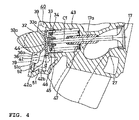
- the axis line C1 of the exhaust valve 17 is inclined to extend downwardly toward the front part, as shown in Fig. 2 and Fig. 4.
- the exhaust pipe 20 is extended rearward from the cylinder head 12 passing along the area to the right of the crankcase 4, and is connected to a muffler 21 in the area to the right of the rear arm 9.
- the object provided forward of the engine 2 and indicated with a reference numeral 22 represents a fuel tank.
- Another object located forward of the fuel tank 22 and indicated with a reference numeral 23 represents a radiator.
- a storage box 24 is provided above the engine 2.
- the storage box 24 is formed with the capacity to accommodate 2 (two) helmets (not shown), with its access opening located in the upper part being opened and closed by a seat.
- the portions within the storage box 24 for accommodating each of the two helmets are shown with reference numerals 24a and 24b.
- the numeral 25 indicates a combustion chamber
- 26 indicates an intake port to be opened and closed by the intake valve 16
- 27 indicates an exhaust port to be opened and closed by the exhaust valve 17
- 28 and 29 indicate piston and connecting rod respectively.
- the valve system 18 on the engine 2 is to drive two each of the intake valves 16 and the exhaust valves 17.
- the valve system 18 includes components such as an intake cam shaft 31 and an exhaust cam shaft 32 accommodated in the valve train cam chamber 13 and each being arranged to locate above and below the cylinder axis line C, valve lifters 33 with which these cam shafts 31 and 32 are engaged via cams, and a valve spring 34 urging the intake valve 16 and the exhaust valve 17 to the closing direction.
- Driving systems for the intake valve 16 and for the exhaust valve 17 are constructed axisymmetrically relative to the axial line C of the cylinder 7.
- the intake cam shaft 31 and the exhaust cam shaft 32, with each axis line extending in the width direction of the scooter 6, are attached rotatably around its axis line and also in the removable manner by means of a cam cap (not shown) to the bearings 35 and 36 located to the left of the cylinder head 12 (refer to the Fig. 3) and to the bearings 37 and 38 located to the right of the cylinder head 12.
- the intake cam shaft 31 and the exhaust cam shaft 32 have cams 31a and 32a (refer to the Fig. 2 and the Fig. 4) respectively at two places.
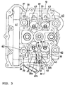
- Fig. 3 depicts the cylinder head 12 as it is viewed from the front of the scooter 6, thus the right side of the Fig. 3 represents the left side of the scooter.
- the bolt holes for screwing the fastening bolts to secure the cam cap to the cylinder head 12 are indicated by the reference numeral 39 in Fig. 3 and Fig. 4.
- the cam accommodating spaces 40 to the left and the right are formed on the cylinder head 12 in the places corresponding to the intake valves 16 and the exhaust valves 17, and the bearings 35 and 36 located to the left are provided between the left and the right cam accommodating spaces 40.
- the bearings 37 and 38 located to the right are provided between a timing chain accommodating space 41 formed in the right end of the cylinder head 12, and those cam accommodating spaces 40 located on the right among the left and the right cam accommodating spaces 40 and 40.
- a stopper 42 described in the sections below, is provided below the exhaust cam shaft bearing 36 that is one of the bearings 35 and 36 located on the left.
- the valve lifters 33 take the shape of a bottomed cylinder. Also, the valve lifters 33 are slidably fitted into valve lifter guide holes 43 in the cylinder head 12, with the cams 31a and 32a provided on the intake cam shaft 31 and the exhaust cam shaft 32 respectively being cam-engaged with their top faces 33a.
- the guide holes 43 are formed so that it is along the axial line with the intake valves 16 and the exhaust valves 17, and so that the end portion of the intake valves 16 and the exhaust valves 17 are internally engaging with them. Also, the guide holes 43 are open to the cam accommodating spaces 40 in the cylinder head 12, as shown in Fig. 3.
- a shim 44 is interposed between the internal bottom face of the valve lifter 33 and valve stem 16a on the intake valves 16, and valve stem 17a on the exhaust valves 17 for adjusting the valve clearance.
- valve spring 34 is provided between a spring retainer 46 attached to the stem end portion of each intake valve 16 and exhaust valve 17 via a cotter pin 45, and a spring seat 47 provided at the bottom of the guide hole 43.
- the valve spring 34 is urging the intake valve 16 and the exhaust valve 17 to their closed position.
- the vertical wall 51 is extending downward from the left bearing 36 for the exhaust cam shaft 32, and the front end face 51a of the vertical wall 51 is included in the end area of the cylinder head 12 on the side of cylinder head cover 14.
- the stopper 42 is provided with a supporting plate 42a removably secured by the fastening screw 52 to the front end face 51a of the vertical wall 51, and stopper pieces 42b and 42b integrally formed on the supporting plate 42a at both ends along the scooter's width direction.
- the front end face 51a is formed so that it comes lower than a mating face 36a (refer to the Fig. 4) to which the cam cap on the bearing 36 is connected (so that it is located to the rear). Also, it is constructed such that head of the fastening screw 52 for securing the supporting plate 42a is in the position lower than the mating face 36a.
- Each stopper piece 42b is provided extending to the rear and to the upward within the cam accommodating space 40 in parallel to both side of the vertical wall 51 and the bearing 36. As shown in Fig. 2 and Fig. 4, each stopper piece 42b on the stopper 42 is formed opposite to the top face 33a of each valve lifter 33 for exhaust valves located lower than the axial line C of the cylinder 7. More specifically, as shown in Fig. 4, each stopper piece 42b is formed to be spaced from the top face 33a by a gap "d", and at the same time to face opposite to the top face 33a, when circular base area of the cam 32a on the exhaust cam shaft 32 is cam-engaged with the top face 33a of the valve lifter 33 for the exhaust valve. In these two stopper pieces 42b, one stopper piece 42b located to the right faces to the valve lifter 33 for the right exhaust valve, and the other stopper piece 42b located to the left faces to the valve lifter 33 for the left exhaust valve.
- the intake cam shaft 31 and the exhaust cam shaft 32 rotate, and then the valve lifters 33, the intake valves 16, and the exhaust valves 17 are driven to follow the rotation of the cam 31a and the cam 32a each provided on both of the cam shafts 31 and 32.
- this engine 2 is kept mounted on the scooter 6 when its intake cam shaft 31 and/or the exhaust cam shaft 32 are replaced as part of the engine maintenance work or in some other situation.
- the valve lifter 33 for the exhaust valve tends to come down along the guide hole 43 by its own weight, however, the valve lifter 33 stops as it is abutted against the stopper 42 to prevent it from falling off the cylinder 7.
- the parts including the valve lifter 33 is kept assembled to the cylinder head 12 even when the exhaust cam shaft 32 is removed during the maintenance work.
- the shims 44 are interposed between the intake valves 16 and exhaust valves 17, and the internal bottom face of the valve lifter 33.
- the shims 44 are smaller part compared with the valve lifters 33, the shims 44 can be lost easily if they fall off together with the valve lifters 33. As described above, however, falling-off of the valve lifters 33 is prevented by the stopper 42, thus the shims 44 are prevented from falling off as well so as to prevent them from getting lost.
- the axial line C of the cylinder 7 may be extended downwardly to the front part.
- the stopper 42 may be provided to work on the valve lifters 33 for the intake valves 16.
Landscapes
- Engineering & Computer Science (AREA)
- Mechanical Engineering (AREA)
- General Engineering & Computer Science (AREA)
- Valve-Gear Or Valve Arrangements (AREA)
- Cylinder Crankcases Of Internal Combustion Engines (AREA)
Abstract
In a scooter engine having valve lifters (33) interposed between
intake valves (16) and a cam shaft (31), as well as between exhaust
valves (17) and a cam shaft (32), with its axial line (C) of a
cylinder (7) extending toward the front part of the vehicle body, a
stopper (42) is provided in the cylinder (7) in the opposite position
to a top face (33a) of the valve lifters (33). The top face (33a) of
the valve lifters (33) is abutted against the stopper (42) when the
valve lifters (33) move to fall off a cylinder head (12) as the cam
shaft is removed from the cylinder head (12), thus the valve lifters
(33) are prevented from falling off the cylinder (7) by the stopper
(42). In this way, the valve lifters (33) are be kept assembled to
the cylinder (7) even when the cam shaft is removed during the
maintenance work. In other words, the DOHC engine (2) can be
installed on a scooter while preventing the valve lifters (33) from
falling off in the course of maintenance work.
Description
This invention relates to a DOHC engine in a straddle-type vehicle
mounted in the manner that cylinder axis line extends toward the
front part of a vehicle.
Conventionally, some four-cycle engines mounted on a type of
motorcycle, a scooter, have cylinder axis line extending toward the
front part of a vehicle, with an intake system connected to the upper
face of a cylinder head, and with an exhaust pipe connected to its
bottom face. So called SOHC valve system is used in most of the
engines of this kind, in which single cam shaft is made to drive both
an intake valve and an exhaust valve. In this type of valve system,
the intake valve and the exhaust valve is connected respectively via
a rocker arm to an intake valve cam and an exhaust valve cam formed
on a cam shaft.
Besides the SOHC described above, there is DOHC valve system used
in a four-cycle engine mounted on other types of motorcycle, in which
an intake valve and an exhaust valve are driven respectively by each
individual cam shaft. Valve system of the DOHC engine is to be, in
general, equipped with a valve lifter taking the shape of a bottomed
cylinder at the end of the intake valve and at the end of the exhaust
valve respectively, and a cam on an intake cam shaft or on an exhaust
cam shaft is closely contacted with the top face of the valve lifter.
The valve lifter is slidably fitted into valve lifter guide hole in a
cylinder head, and positioned along the axial line of the intake
valve and the exhaust valve. In addition, a thin plate shim is
interposed between the internal bottom face of the valve lifter and
the intake valve or the exhaust valve for adjusting the gap between
the top face and the circular base area of the cam (valve clearance).
Inventor desired to improve the driving performance of a scooter by
adopting the DOHC valve system described above in the scooter engine.
However, when the DOHC engine is mounted on a scooter with its
cylinder axial line extending toward the front part of the vehicle,
the following problem may arise in trying to perform maintenance work
while keeping the engine mounted on the vehicle body in the
aforementioned manner and removing the cam shaft.
That is, in the mounted condition described above, each axial line
of intake valves and exhaust valves, especially the exhaust valves
located at the lower part, and of the valve lifter mounted at the end
of the exhaust valve will extend downward to the front. Therefore,
when the cam shaft is removed from the cylinder head in the
abovementioned condition, no member is available for stopping an
exhaust valve lifter, causing the valve lifter to fall off the
cylinder head by its own weight. When the valve lifter falls off
from the cylinder head, the shim interposed between the valve lifter
and the exhaust valve will fall off as well. Since the shim is a
smaller part compared with the valve lifter, it can be easily lost if
it falls off the cylinder without being recognized by a worker.
In consideration of the circumstance described above, this
invention was made intending to prevent the valve lifters and the
shims from falling-off during the maintenance work when DOHC engine
is mounted on a scooter.
This invention is an arrangement that, in a scooter engine having a
valve lifters interposed between intake valves and a cam shaft, as
well as between exhaust valves and a cam shafts, with its cylinder
axis line extending toward the front part of the vehicle body, a
stopper is provided in the cylinder in the opposing position to a top
face of the valve lifter.
According to this invention, the top face of the valve lifter is
abutted against the stopper when the valve lifter moves to fall off
the cylinder as the cam shaft is removed from the cylinder, thus the
valve lifter is prevented from falling off the cylinder by the
stopper. In this way, the valve lifter will be kept assembled to the
cylinder even when the cam shaft is removed during the maintenance
work. In other words, the DOHC engine can be installed on a scooter
while preventing the valve lifter from falling off in the course of
maintenance work.
In the above-mentioned invention, a shim may be interposed between
the intake or exhaust valve and the internal bottom face of the valve
lifter.
Here, the shim can be easily lost once it falls off as the valve
lifter falls off. As described above, however, the valve lifter is
prevented from falling off by the stopper, thus the shim is prevented
from falling off as well, so as to avoid losing it.
This invention will be described in detail referring to the
attached drawings.
In these figures, the reference numeral 1 denotes a unit-swing type
power unit equipped with an engine 2. The power unit 1 integrally
incorporates the engine 2 and a rear wheel 3. The power unit 1 is
supported in the vertically swingable manner by a vehicle body frame
(not shown) of a scooter 6 via a link (not shown) which is jointed to
a joint boss 5 provided at the upper end of a crankcase 4 of the
engine 2. Note that the left and the right in the following sections
denote the direction in the vehicle width direction of the scooter 6,
looking toward the front part of the scooter.
The engine 2 is a water-cooled, single cylinder DOHC engine. The
engine 2 is provided with a crankcase 4, and a cylinder 7 projected
from the crankcase 4. Also, it is provided with a transmission case
8 extending in the vehicle's longitudinal direction in the area to the
left of the rear wheel. The rear wheel 3 is supported by the
transmission case 8, and a rear arm 9 located in the area to the
right of the rear wheel 3 and extending rearward from the crankcase 4.
In addition, the rear end of the transmission case 8 and the rear end
of the rear arm 9 are respectively connected to the vehicle frame via
a cushion unit 10.
The cylinder 7 includes, as shown in Fig. 1 and Fig. 2, a cylinder
body 11 projecting from the crankcase 4 toward the vehicle front and
obliquely upward, a cylinder head 12 attached to the front end of the
cylinder body 11, and a cylinder head cover 14 attached to the front
end of the cylinder head 12, with a valve train cam chamber 13 (refer
to the Fig. 2) being formed between the cylinder head 12 and the
cylinder head cover 14.
Since the cylinder 7 is projecting from the crankcase 4 toward the
vehicle front and obliquely upward, the axis line C of the cylinder 7
is extending in forward and obliquely upward direction. In this
embodiment, the axis line C is slightly inclined upward toward the
front part, extending to the point at the vicinity of the upper edge
of a front wheel 15.
The cylinder head 12 removably supports two each of the intake
valves 16 and the exhaust valves 17, and also supports valve system
18 for driving these intake valves 16 and the exhaust valves 17, a
spark plug (now shown), and the like. An intake system 19 is
connected to the upper surface of the cylinder head 12, and an
exhaust pipe 20 is connected to its bottom surface. When the engine
2 is mounted on the scooter 6, the axis line C1 of the exhaust valve
17 is inclined to extend downwardly toward the front part, as shown
in Fig. 2 and Fig. 4. As shown in Fig. 1, the exhaust pipe 20 is
extended rearward from the cylinder head 12 passing along the area to
the right of the crankcase 4, and is connected to a muffler 21 in the
area to the right of the rear arm 9.
In Fig. 1, the object provided forward of the engine 2 and
indicated with a reference numeral 22 represents a fuel tank.
Another object located forward of the fuel tank 22 and indicated with
a reference numeral 23 represents a radiator. In addition, a storage
box 24 is provided above the engine 2. The storage box 24 is formed
with the capacity to accommodate 2 (two) helmets (not shown), with
its access opening located in the upper part being opened and closed
by a seat. The portions within the storage box 24 for accommodating
each of the two helmets are shown with reference numerals 24a and 24b.
Further in Fig. 2, the numeral 25 indicates a combustion chamber, 26
indicates an intake port to be opened and closed by the intake valve
16, 27 indicates an exhaust port to be opened and closed by the
exhaust valve 17, and 28 and 29 indicate piston and connecting rod
respectively.
The valve system 18 on the engine 2 is to drive two each of the
intake valves 16 and the exhaust valves 17. As shown in Fig. 2 and
Fig. 4, the valve system 18 includes components such as an intake cam
shaft 31 and an exhaust cam shaft 32 accommodated in the valve train
cam chamber 13 and each being arranged to locate above and below the
cylinder axis line C, valve lifters 33 with which these cam shafts 31
and 32 are engaged via cams, and a valve spring 34 urging the intake
valve 16 and the exhaust valve 17 to the closing direction. Driving
systems for the intake valve 16 and for the exhaust valve 17 are
constructed axisymmetrically relative to the axial line C of the
cylinder 7.
The intake cam shaft 31 and the exhaust cam shaft 32, with each
axis line extending in the width direction of the scooter 6, are
attached rotatably around its axis line and also in the removable
manner by means of a cam cap (not shown) to the bearings 35 and 36
located to the left of the cylinder head 12 (refer to the Fig. 3) and
to the bearings 37 and 38 located to the right of the cylinder head
12. The intake cam shaft 31 and the exhaust cam shaft 32 have cams
31a and 32a (refer to the Fig. 2 and the Fig. 4) respectively at two
places. Note that Fig. 3 depicts the cylinder head 12 as it is
viewed from the front of the scooter 6, thus the right side of the
Fig. 3 represents the left side of the scooter. The bolt holes for
screwing the fastening bolts to secure the cam cap to the cylinder
head 12 are indicated by the reference numeral 39 in Fig. 3 and Fig.
4.
As shown in Fig. 3, the cam accommodating spaces 40 to the left and
the right are formed on the cylinder head 12 in the places
corresponding to the intake valves 16 and the exhaust valves 17, and
the bearings 35 and 36 located to the left are provided between the
left and the right cam accommodating spaces 40. The bearings 37 and
38 located to the right are provided between a timing chain
accommodating space 41 formed in the right end of the cylinder head
12, and those cam accommodating spaces 40 located on the right among
the left and the right cam accommodating spaces 40 and 40. A stopper
42, described in the sections below, is provided below the exhaust
cam shaft bearing 36 that is one of the bearings 35 and 36 located on
the left.
As shown in Fig. 4, the valve lifters 33 take the shape of a
bottomed cylinder. Also, the valve lifters 33 are slidably fitted
into valve lifter guide holes 43 in the cylinder head 12, with the
cams 31a and 32a provided on the intake cam shaft 31 and the exhaust
cam shaft 32 respectively being cam-engaged with their top faces 33a.
The guide holes 43 are formed so that it is along the axial line with
the intake valves 16 and the exhaust valves 17, and so that the end
portion of the intake valves 16 and the exhaust valves 17 are
internally engaging with them. Also, the guide holes 43 are open to
the cam accommodating spaces 40 in the cylinder head 12, as shown in
Fig. 3.
In addition, a shim 44 is interposed between the internal bottom
face of the valve lifter 33 and valve stem 16a on the intake valves
16, and valve stem 17a on the exhaust valves 17 for adjusting the
valve clearance.
As shown in Fig. 4, the valve spring 34 is provided between a
spring retainer 46 attached to the stem end portion of each intake
valve 16 and exhaust valve 17 via a cotter pin 45, and a spring seat
47 provided at the bottom of the guide hole 43.
The valve spring 34 is urging the intake valve 16 and the exhaust
valve 17 to their closed position.
As shown in Fig. 3 through Fig. 5, the vertical wall 51 is
extending downward from the left bearing 36 for the exhaust cam shaft
32, and the front end face 51a of the vertical wall 51 is included in
the end area of the cylinder head 12 on the side of cylinder head
cover 14. The stopper 42 is provided with a supporting plate 42a
removably secured by the fastening screw 52 to the front end face 51a
of the vertical wall 51, and stopper pieces 42b and 42b integrally
formed on the supporting plate 42a at both ends along the scooter's
width direction. The front end face 51a is formed so that it comes
lower than a mating face 36a (refer to the Fig. 4) to which the cam
cap on the bearing 36 is connected (so that it is located to the
rear). Also, it is constructed such that head of the fastening screw
52 for securing the supporting plate 42a is in the position lower
than the mating face 36a.
Each stopper piece 42b is provided extending to the rear and to the
upward within the cam accommodating space 40 in parallel to both side
of the vertical wall 51 and the bearing 36. As shown in Fig. 2 and
Fig. 4, each stopper piece 42b on the stopper 42 is formed opposite
to the top face 33a of each valve lifter 33 for exhaust valves
located lower than the axial line C of the cylinder 7. More
specifically, as shown in Fig. 4, each stopper piece 42b is formed to
be spaced from the top face 33a by a gap "d", and at the same time to
face opposite to the top face 33a, when circular base area of the cam
32a on the exhaust cam shaft 32 is cam-engaged with the top face 33a
of the valve lifter 33 for the exhaust valve. In these two stopper
pieces 42b, one stopper piece 42b located to the right faces to the
valve lifter 33 for the right exhaust valve, and the other stopper
piece 42b located to the left faces to the valve lifter 33 for the
left exhaust valve.
In the engine 2 having the valve system 18 constructed as described
above, the intake cam shaft 31 and the exhaust cam shaft 32 rotate,
and then the valve lifters 33, the intake valves 16, and the exhaust
valves 17 are driven to follow the rotation of the cam 31a and the
cam 32a each provided on both of the cam shafts 31 and 32.
By the way, this engine 2 is kept mounted on the scooter 6 when its
intake cam shaft 31 and/or the exhaust cam shaft 32 are replaced as
part of the engine maintenance work or in some other situation. In
such cases, once the exhaust cam shaft 32 is removed from the
cylinder head 12, the valve lifter 33 for the exhaust valve tends to
come down along the guide hole 43 by its own weight, however, the
valve lifter 33 stops as it is abutted against the stopper 42 to
prevent it from falling off the cylinder 7.
Thus, in the engine 2, the parts including the valve lifter 33 is
kept assembled to the cylinder head 12 even when the exhaust cam
shaft 32 is removed during the maintenance work.
Further, as described above, the shims 44 are interposed between
the intake valves 16 and exhaust valves 17, and the internal bottom
face of the valve lifter 33.
Since the shims 44 are smaller part compared with the valve lifters
33, the shims 44 can be lost easily if they fall off together with
the valve lifters 33. As described above, however, falling-off of
the valve lifters 33 is prevented by the stopper 42, thus the shims
44 are prevented from falling off as well so as to prevent them from
getting lost.
The description above is in accordance with an example shown in the
attached figures, however, the axial line C of the cylinder 7 may be
extended downwardly to the front part. Also, the stopper 42 may be
provided to work on the valve lifters 33 for the intake valves 16.
Claims (2)
- A scooter engine having a valve lifter (33) interposed between intake valves (16) and a cam shaft (31), as well as between exhaust valves (17) and a cam shaft (32), with the axial line (C) of a cylinder (7) extending toward the front part of the vehicle body, wherein a stopper (42) is disposed in the cylinder (7) in the location opposite to a top face (33a) of the valve lifter (33).
- The scooter engine according to Claim 1, wherein shims (44) are interposed between the intake valves (16) and the exhaust valves (17), and internal bottom faces of the valve lifters (33).
Applications Claiming Priority (3)
| Application Number | Priority Date | Filing Date | Title |
|---|---|---|---|
| JP2002181341 | 2002-06-21 | ||
| JP2002181341 | 2002-06-21 | ||
| PCT/JP2003/007629 WO2004001213A1 (en) | 2002-06-21 | 2003-06-16 | Engine for scooter |
Publications (2)
| Publication Number | Publication Date |
|---|---|
| EP1541848A1 true EP1541848A1 (en) | 2005-06-15 |
| EP1541848A4 EP1541848A4 (en) | 2009-06-17 |
Family
ID=29996624
Family Applications (1)
| Application Number | Title | Priority Date | Filing Date |
|---|---|---|---|
| EP03733453A Withdrawn EP1541848A4 (en) | 2002-06-21 | 2003-06-16 | Engine for scooter |
Country Status (6)
| Country | Link |
|---|---|
| US (1) | US7066124B2 (en) |
| EP (1) | EP1541848A4 (en) |
| JP (1) | JP3919017B2 (en) |
| AU (1) | AU2003241682A1 (en) |
| TW (1) | TW579408B (en) |
| WO (1) | WO2004001213A1 (en) |
Cited By (1)
| Publication number | Priority date | Publication date | Assignee | Title |
|---|---|---|---|---|
| DE102005011224B4 (en) * | 2005-03-11 | 2013-05-29 | Audi Ag | cylinder head |
Families Citing this family (1)
| Publication number | Priority date | Publication date | Assignee | Title |
|---|---|---|---|---|
| JP2007146731A (en) * | 2005-11-25 | 2007-06-14 | Yamaha Motor Co Ltd | Engine and vehicle |
Family Cites Families (9)
| Publication number | Priority date | Publication date | Assignee | Title |
|---|---|---|---|---|
| JPS61137812A (en) | 1984-12-07 | 1986-06-25 | Ajinomoto Co Inc | Detergent composition having pearly luster |
| JPS62237016A (en) | 1986-04-08 | 1987-10-17 | Nissan Motor Co Ltd | Valve system for internal combustion engine |
| JPS6373502A (en) | 1986-09-16 | 1988-04-04 | Tokin Corp | Manufacture of rare earth magnet |
| JPS6373502U (en) * | 1986-10-31 | 1988-05-17 | ||
| JP2815721B2 (en) | 1991-03-20 | 1998-10-27 | 株式会社小糸製作所 | Automotive headlamp |
| US5678514A (en) * | 1996-04-02 | 1997-10-21 | Ford Global Technologies, Inc. | Valve lifter retainer for an internal combustion engine |
| US5709180A (en) * | 1997-02-06 | 1998-01-20 | General Motors Corporation | Narrow cam two-step lifter |
| JP4067662B2 (en) * | 1998-09-14 | 2008-03-26 | 本田技研工業株式会社 | Internal combustion engine valve device having valve deactivation mechanism |
| JP2001123833A (en) * | 1999-10-26 | 2001-05-08 | Yamaha Motor Co Ltd | Forced air-cooled direct injection engine |
-
2003
- 2003-06-03 TW TW092115095A patent/TW579408B/en not_active IP Right Cessation
- 2003-06-16 AU AU2003241682A patent/AU2003241682A1/en not_active Abandoned
- 2003-06-16 JP JP2004515496A patent/JP3919017B2/en not_active Expired - Fee Related
- 2003-06-16 EP EP03733453A patent/EP1541848A4/en not_active Withdrawn
- 2003-06-16 US US10/510,318 patent/US7066124B2/en not_active Expired - Lifetime
- 2003-06-16 WO PCT/JP2003/007629 patent/WO2004001213A1/en not_active Ceased
Cited By (1)
| Publication number | Priority date | Publication date | Assignee | Title |
|---|---|---|---|---|
| DE102005011224B4 (en) * | 2005-03-11 | 2013-05-29 | Audi Ag | cylinder head |
Also Published As
| Publication number | Publication date |
|---|---|
| EP1541848A4 (en) | 2009-06-17 |
| AU2003241682A1 (en) | 2004-01-06 |
| TW200401075A (en) | 2004-01-16 |
| JP3919017B2 (en) | 2007-05-23 |
| US20050211213A1 (en) | 2005-09-29 |
| JPWO2004001213A1 (en) | 2005-10-20 |
| WO2004001213A1 (en) | 2003-12-31 |
| TW579408B (en) | 2004-03-11 |
| US7066124B2 (en) | 2006-06-27 |
Similar Documents
| Publication | Publication Date | Title |
|---|---|---|
| CN100434658C (en) | Valve trains with roller/rocker arms, four-stroke engines and motorcycles with four-stroke engines mounted thereon | |
| CN101550885B (en) | Cylinder head structure in four-cycle engine | |
| US6935289B2 (en) | Valve drive system for four-stroke engine | |
| JP6713710B2 (en) | Slant type internal combustion engine | |
| JPS644045B2 (en) | ||
| AU2003242499B2 (en) | Four-cycle Engine | |
| US20090241880A1 (en) | Rocker shaft support structure in four-cycle engine | |
| JP2000130254A (en) | Vehicle engine | |
| US7066124B2 (en) | Engine for scooter | |
| JP5049874B2 (en) | Cylinder head structure in engine | |
| US7650862B2 (en) | Engine and motorcycle | |
| EP1403497A1 (en) | Camshaft bearing structure for over-head camshaft type internal combustion engine | |
| JP6711147B2 (en) | Engine chain cover structure | |
| KR20040026600A (en) | Ohc type internal combustion engine | |
| JP6349425B2 (en) | Rocker shaft arrangement structure of 4-stroke internal combustion engine | |
| US7503299B2 (en) | Twincam engine and motorcycle comprising the same | |
| US10190530B2 (en) | Power unit | |
| JP6897212B2 (en) | Engine exhaust purification device and vehicle | |
| JP4629003B2 (en) | Valve operating device for internal combustion engine | |
| JP2014070601A (en) | Rocker shaft arrangement structure of four-stroke internal combustion engine | |
| JPH051807U (en) | Engine cylinder head structure | |
| JP2024021974A (en) | Oil passage structure of internal combustion engine | |
| JP2694898B2 (en) | Valve system for 4-cycle engine | |
| JPH0262708B2 (en) | ||
| JPH06288205A (en) | Valve system |
Legal Events
| Date | Code | Title | Description |
|---|---|---|---|
| PUAI | Public reference made under article 153(3) epc to a published international application that has entered the european phase |
Free format text: ORIGINAL CODE: 0009012 |
|
| 17P | Request for examination filed |
Effective date: 20050119 |
|
| AK | Designated contracting states |
Kind code of ref document: A1 Designated state(s): AT BE BG CH CY CZ DE DK EE ES FI FR GB GR HU IE IT LI LU MC NL PT RO SE SI SK TR |
|
| AX | Request for extension of the european patent |
Extension state: AL LT LV MK |
|
| DAX | Request for extension of the european patent (deleted) | ||
| A4 | Supplementary search report drawn up and despatched |
Effective date: 20090515 |
|
| 17Q | First examination report despatched |
Effective date: 20091110 |
|
| STAA | Information on the status of an ep patent application or granted ep patent |
Free format text: STATUS: THE APPLICATION IS DEEMED TO BE WITHDRAWN |
|
| 18D | Application deemed to be withdrawn |
Effective date: 20100323 |