EP1541744A1 - Household clothes drying machine with improved condenser - Google Patents
Household clothes drying machine with improved condenser Download PDFInfo
- Publication number
- EP1541744A1 EP1541744A1 EP03028410A EP03028410A EP1541744A1 EP 1541744 A1 EP1541744 A1 EP 1541744A1 EP 03028410 A EP03028410 A EP 03028410A EP 03028410 A EP03028410 A EP 03028410A EP 1541744 A1 EP1541744 A1 EP 1541744A1
- Authority
- EP
- European Patent Office
- Prior art keywords
- air
- drying
- condenser
- flow
- cooling
- Prior art date
- Legal status (The legal status is an assumption and is not a legal conclusion. Google has not performed a legal analysis and makes no representation as to the accuracy of the status listed.)
- Withdrawn
Links
Images

Classifications
-
- D—TEXTILES; PAPER
- D06—TREATMENT OF TEXTILES OR THE LIKE; LAUNDERING; FLEXIBLE MATERIALS NOT OTHERWISE PROVIDED FOR
- D06F—LAUNDERING, DRYING, IRONING, PRESSING OR FOLDING TEXTILE ARTICLES
- D06F58/00—Domestic laundry dryers
- D06F58/20—General details of domestic laundry dryers
- D06F58/24—Condensing arrangements
Definitions
- the present invention refers to an improved kind of clothes drying machine, preferably of the type for use in households, which is provided with means for removing the moisture from the drying air comprising a condenser through which there is conveyed, further to the flow of the drying air itself, a second flow of cooling air, occurring of course separately from said flow of drying air, which is taken in from the outside ambient and appropriately delivered to flow through and, as a result, cool down said condenser.
- the present invention preferably applies to clothes drying machines which, further to a condenser, are also provided with:
- the hot air Upon having been blown into the clothes-holding drum, the hot air causes the moisture contained in the clothes to evaporate, thereby becoming almost saturated, or even fully saturated, therewith.
- This hot, moisture-laden air is then pushed further by said fan, thereby creating a continuous flow that is eventually sent into an appropriate condensation arrangement, which is usually constituted by a heat-exchanger flown through - along the so-called “hot” path - by said flow of hot moisture-laden air and - along the so-called “cold” path - by a substantially continuous flow of fresh air that is taken in from the outside ambient and is exhausted again into the outside ambient upon having so flown through said heat-exchanger.
- a drum 1 adapted to hold the clothes to be dried, to which there is associated a conduit 2 for the circulation of the drying air; the latter flows also through a condenser 3, which is adapted to cause the moisture contained in the drying air flowing therethough to condense, said condenser being furthermore flown through by a flow of "cold" air, i.e. air taken in from the outside ambient and sent to said condenser 3 via a corresponding conduit 4.
- Both conduits 2 and 4 contain two respective fans 5, 6 therewithin, which are provided to circulate the drying-air flow and the cooling-air flow, respectively. Furthermore, the shafts of said two fans 5 and 6 are connected in any of the manners known as such in the art, even via appropriate mechanisms and gears, to a single motor 7 so that the rotation of this motor causes said two fans to correspondingly rotate in a synchronous manner.
- This motor 7 is controlled by appropriate control means (not shown), which are adapted to let it revolve in its two possible directions of rotation; as a result, this allows said two fans to be caused to selectively rotate in either direction, but in all cases in a mutually consistent manner (i.e., when a first fan rotates in a definite direction, the second fan will always rotate in a single and sole direction; and when the first fan changes its direction of rotation, the second fan will change its own direction of rotation, too).
- the motor driving the fan may also be used, via appropriate motion transmission means, to also rotatably drive the clothes-holding drum; in this connection, it is a common practice for said motor to be so controlled as to revolve for short periods of time in its normal, i.e. main direction of rotation, in which said short periods of rotation in that direction are alternated with other short periods during which said motor revolves in the opposite, i.e. secondary direction of rotation.
- said machine is improved in the following manner: with reference to Figures 1 and 2, and stressing again the fact the condenser 3 is flown through by two distinct streams of drying air and cooling air, there are provided means that are practically adapted to cause the sole flow of drying air, or alternatively the sole flow of cooling air, to bypass, i.e. to leave out the passage through the condenser.
- Such bypass starts upstream of the condenser and terminates downstream thereof, where it is restored into its original flow-path, so that it is the sole condenser that is actually involved by the corresponding diversion of said airflow.
- the present invention may be practically embodied by providing an auxiliary cooling conduit 10, which starts by branching off from a section of the cooling conduit 4 upstream of the condenser and extends further towards the exhaust outlet 11 without passing through the condenser 3.
- a diverting means which is preferably constituted by a valve 13 featuring an inlet way 14, formed by the cooling-air conduit upstream thereof, and two outlet ways 15 and 16: one of these outlet ways is formed by the same portion of conduit leading to the condenser 3, whereas the other outlet way 16 opens into said auxiliary cooling-air conduit 10.
- This valve is adapted to receive the flow of cooling air being taken in from outside, and to direct it towards either the condenser 3 or the auxiliary conduit 10 that bypasses said condenser.
- the valve 13 makes preferably use of a moving partition 17 which, as appropriately actuated, is capable of selectively close either one or the other of said outlet ways of the flow-diverting valve, thereby enabling the flow of cooling air to be directed towards the preselected conduit.
- valve is actuated by an electrically operable actuator 18 of a kind known as such in the art, which is operated in accordance with the phase of the operation cycle being performed by the machine.
- the drying air is heated up gradually to its process temperature, while becoming increasingly laden with the moisture it removes from the clothes.
- the actuator 18 is operated so that the cooling air in the conduit 4 is now conveyed into the condenser, thereby restoring the normal mode of operation of the machine and enabling said flow of hot moisture-laden air to be cooled down and the moisture contained therein to condense.
- the present invention may anyway be also embodied in a manner differing from the one described just above, in which this different embodiment is practically aimed at bringing about a reverse mode of operation as far as the crossing of said flows inside the condenser is concerned.
- the object of the present invention which is basically aimed at preventing the flows of drying and cooling air from crossing each other inside the condenser for a pre-established period of time during the drying process, may be achieved by either diverting the flow of cooling air, so as this has been just described above, or by leaving the cooling-air conduit unaltered and providing a condenser bypass arrangement on the drying-air conduit, instead.
- the desired temporary avoidance of a mutual crossing of the airflows in the condenser may be equally well obtained regardless of which conduit, i.e. the cooling-air conduit or the drying-air conduit, is provided with a bypass feature to go round the condenser.
- the drying-air conduit 2 is therefore provided with an auxiliary drying-air conduit 20, which bypasses the condenser for joining again the same main conduit 2 downstream of the condenser.
- drying-air conduit that will be provided with a respective three-way valve 21 and a respective actuator 22 in this case.
- either of the two auxiliary conduits 11 and 12, according to which one of them is actually used may be so provided and arranged as to run contiguous or, still better, adjacent to a surface 30 of said condenser; this enables the overall space requirement of said auxiliary conduits to be reduced to the maximum possible extent and, in particular, the space existing between these auxiliary conduits and other functional parts of the machine, including in particular the condenser itself, which would otherwise be scarcely able to be used owing to their size or a poor accessibility, to be minimized.
- the surfaces 30 of the condenser and 31 of one of said auxiliary conduits may be advantageously integrated with each other, i.e. unified into a single wall 33 that is common to both said elements, in such a manner as to make the resulting assembly much more compact and simple in its construction, thereby reaching at the same time also an advantage in terms of a saving, albeit small, in material usage.
Landscapes
- Engineering & Computer Science (AREA)
- Textile Engineering (AREA)
- Detail Structures Of Washing Machines And Dryers (AREA)
Abstract
Description
- The present invention refers to an improved kind of clothes drying machine, preferably of the type for use in households, which is provided with means for removing the moisture from the drying air comprising a condenser through which there is conveyed, further to the flow of the drying air itself, a second flow of cooling air, occurring of course separately from said flow of drying air, which is taken in from the outside ambient and appropriately delivered to flow through and, as a result, cool down said condenser.
- Although reference to an autonomous, i.e. self-standing clothes drying machine will be made throughout the following description, it shall be appreciated that what is set forth below may similarly be applied to and, therefore, be suitable for combined clothes washing and drying machines.
- The machines, which the present invention refers to, are generally known in the art. They have on the other hand been described, along with a detailed discussion of a technical nature on the advantages and the drawbacks of a number of different variations in the design and general embodiment thereof, in the Italian patent application no. PN2003U000015 filed by this same Applicant with the title "Household clothes drying machine with improved fan", to which reference should therefore be made for reasons of greater convenience and brevity in this description.
- The present invention preferably applies to clothes drying machines which, further to a condenser, are also provided with:
- two distinct fans for blowing the drying air and the condenser cooling air, respectively,
- a single motor adapted to drive both said fans at the same time,
- said motor being adapted to be controlled so as to selectively rotate in the two opposite directions.
- However, it will be readily appreciated that the present invention may be equally applied to condenser-type clothes drying machines of a traditional kind, i.e. provided with a regular condenser, but lacking the other features as indicated above, although the aims and advantages pursued and reachable with the present invention would of course not be fully achieved in this case.
- Largely known in the art are clothes drying machines that operate either by condensing a flow of hot air, which is first blown into the clothes-holding drum and, while circulating therethrough, removes moisture from the same clothes, or by exhausting said flow of hot moisture-laden air directly outside.
- Upon having been blown into the clothes-holding drum, the hot air causes the moisture contained in the clothes to evaporate, thereby becoming almost saturated, or even fully saturated, therewith. This hot, moisture-laden air is then pushed further by said fan, thereby creating a continuous flow that is eventually sent into an appropriate condensation arrangement, which is usually constituted by a heat-exchanger flown through - along the so-called "hot" path - by said flow of hot moisture-laden air and - along the so-called "cold" path - by a substantially continuous flow of fresh air that is taken in from the outside ambient and is exhausted again into the outside ambient upon having so flown through said heat-exchanger.
- Usually, even said flow of fresh air in the so-called "cold" path is activated and maintained by a fan, which is driven in a traditional manner by a respective electric motor.
- Largely known in the art is also the fact that, during the initial phase of the drying process, no need would be actually felt for the drying air to be caused to undergo such moisture-removal process by letting it pass through the condenser, since it in fact undergoes a certain extent of condensation by itself owing to a still quite low temperature prevailing in the machine. Moreover, during the initial phase of the drying process, the need arises for both the clothes to be dried and the drying air itself to be heated up to the steady-state temperature thereof, so that, in this initial period, condensation taking place at the condenser would anyway be quite limited and, therefore, would make a cooling down of the drying air plainly useless, if not even detrimental.
- However, since the motor used to rotatably drive the clothes-holding drum is connected also with the fans circulating the flows of air in the afore-cited "hot" and "cold" paths, it ensues that, even if not desired, the condenser is anyway flown through by the cooling air also during said initial period of the drying process.
- In view of doing away with such inherent drawback, a solution is disclosed in the above-cited patent publication, which enables the rotation of the cooling fan in its main operation mode to be fully eliminated during said initial period, while allowing it to only rotate in its secondary operation mode, so as to achieve the twofold advantage of a rather reduced operating noise and a reduction in the aggregate drying time, without suffering the penalty of a poorer condensation. However, another drawback is seen in this case, in that by so limiting the motor to operate in a single direction of rotation, albeit as far as only the initial phase of the drying process is concerned, a certain effect of entanglement of the clothes to be dried is brought about, and this effect is then only in part straightened out during the subsequent phases of the drying process.
- It would therefore be desirable, and it is actually a main purpose of the present invention, to provide a condenser-type clothes drying machine, which is provided with a single motor to drive both the drying-air fan and the cooling-air fan, is capable of ensuring a standard-level drying performance, and is however capable of eliminating the above-cited drawbacks of both the cooling air untimely flowing through the condenser during the initial phases of the drying process and the drum having to rotate in a single direction of rotation during said same initial phases.
- According to the present invention, this aim is reached, along with further ones that will be apparent from the following description, in a condenser-type clothes drying machine incorporating the features as recited in the appended claims.
- Anyway, features and advantages of the present invention will be more readily understood from the description that is given below by mere way of non-limiting example with reference to the accompanying drawings, in which:
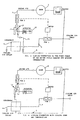
- Figures 1 and 2 are operational schematic views of an embodiment of a machine according to the present invention, during the initial phase of the drying process and the subsequent phase occurring under steady-state conditions, respectively;
- Figures 3 and 4 are operational schematic views of a second embodiment of a machine according to the present invention, during the initial phase of the drying process and the subsequent phase occurring under steady-state conditions, respectively;
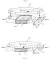
- Figure 5 is a perspective, cut-away view of a significant portion of the condenser and associated devices in a machine according to the present invention;
- Figure 6 is a perspective, partially see-through view of the parts illustrated in Figure 5.
- In a clothes drying machine according to a prior-art embodiment there is provided a
drum 1 adapted to hold the clothes to be dried, to which there is associated aconduit 2 for the circulation of the drying air; the latter flows also through acondenser 3, which is adapted to cause the moisture contained in the drying air flowing therethough to condense, said condenser being furthermore flown through by a flow of "cold" air, i.e. air taken in from the outside ambient and sent to saidcondenser 3 via a corresponding conduit 4. - Both
conduits 2 and 4 contain tworespective fans 5, 6 therewithin, which are provided to circulate the drying-air flow and the cooling-air flow, respectively. Furthermore, the shafts of said twofans 5 and 6 are connected in any of the manners known as such in the art, even via appropriate mechanisms and gears, to a single motor 7 so that the rotation of this motor causes said two fans to correspondingly rotate in a synchronous manner. This motor 7 is controlled by appropriate control means (not shown), which are adapted to let it revolve in its two possible directions of rotation; as a result, this allows said two fans to be caused to selectively rotate in either direction, but in all cases in a mutually consistent manner (i.e., when a first fan rotates in a definite direction, the second fan will always rotate in a single and sole direction; and when the first fan changes its direction of rotation, the second fan will change its own direction of rotation, too). - In the traditional mode of operation, the motor driving the fan may also be used, via appropriate motion transmission means, to also rotatably drive the clothes-holding drum; in this connection, it is a common practice for said motor to be so controlled as to revolve for short periods of time in its normal, i.e. main direction of rotation, in which said short periods of rotation in that direction are alternated with other short periods during which said motor revolves in the opposite, i.e. secondary direction of rotation.
- According to the present invention, said machine is improved in the following manner: with reference to Figures 1 and 2, and stressing again the fact the
condenser 3 is flown through by two distinct streams of drying air and cooling air, there are provided means that are practically adapted to cause the sole flow of drying air, or alternatively the sole flow of cooling air, to bypass, i.e. to leave out the passage through the condenser. Such bypass starts upstream of the condenser and terminates downstream thereof, where it is restored into its original flow-path, so that it is the sole condenser that is actually involved by the corresponding diversion of said airflow. - The present invention may be practically embodied by providing an
auxiliary cooling conduit 10, which starts by branching off from a section of the cooling conduit 4 upstream of the condenser and extends further towards theexhaust outlet 11 without passing through thecondenser 3. In the flow-divertingfitting 12 there is provided a diverting means, which is preferably constituted by avalve 13 featuring aninlet way 14, formed by the cooling-air conduit upstream thereof, and twooutlet ways 15 and 16: one of these outlet ways is formed by the same portion of conduit leading to thecondenser 3, whereas theother outlet way 16 opens into said auxiliary cooling-air conduit 10. This valve is adapted to receive the flow of cooling air being taken in from outside, and to direct it towards either thecondenser 3 or theauxiliary conduit 10 that bypasses said condenser. To this purpose, thevalve 13 makes preferably use of a movingpartition 17 which, as appropriately actuated, is capable of selectively close either one or the other of said outlet ways of the flow-diverting valve, thereby enabling the flow of cooling air to be directed towards the preselected conduit. - The above-mentioned valve is actuated by an electrically
operable actuator 18 of a kind known as such in the art, which is operated in accordance with the phase of the operation cycle being performed by the machine. - At this point, it can be clearly inferred that, during the initial phase of the drying process, it becomes possible for said
valve 13 to be so operated as to enable it to direct the flow of cooling air towards the auxiliary conduit 10 (which may even have a small cross-sectional size), so that this flow will not pass through the condenser 3 (Figure 1). As a result, the drying air, which is on the contrary conveyed through thecondenser 3, is by no means cooled down in this phase of the drying process and, furthermore, the driving motor may be allowed to alternately rotate in its two opposite directions of rotation, since the cooling air will anyway not flow through the condenser in either case, thereby achieving the ultimate desired result. - During the initial period of the drying process, the drying air is heated up gradually to its process temperature, while becoming increasingly laden with the moisture it removes from the clothes. When it is eventually desired that such flow of hot moisture-laden air be appropriately cooled down for removing moisture therefrom, the
actuator 18 is operated so that the cooling air in the conduit 4 is now conveyed into the condenser, thereby restoring the normal mode of operation of the machine and enabling said flow of hot moisture-laden air to be cooled down and the moisture contained therein to condense. - The present invention may anyway be also embodied in a manner differing from the one described just above, in which this different embodiment is practically aimed at bringing about a reverse mode of operation as far as the crossing of said flows inside the condenser is concerned. As a matter of fact, the object of the present invention, which is basically aimed at preventing the flows of drying and cooling air from crossing each other inside the condenser for a pre-established period of time during the drying process, may be achieved by either diverting the flow of cooling air, so as this has been just described above, or by leaving the cooling-air conduit unaltered and providing a condenser bypass arrangement on the drying-air conduit, instead.
- From a functional point of view, in fact, the desired temporary avoidance of a mutual crossing of the airflows in the condenser may be equally well obtained regardless of which conduit, i.e. the cooling-air conduit or the drying-air conduit, is provided with a bypass feature to go round the condenser.
- According to this different embodiment of the present invention, and with reference to Figures 3 and 4, the drying-
air conduit 2 is therefore provided with an auxiliary drying-air conduit 20, which bypasses the condenser for joining again the samemain conduit 2 downstream of the condenser. - The way in which said conduit and the devices associated therewith operate and may be implemented is fully similar to the above-described one in connection with the first embodiment considered. Accordingly, it is said drying-air conduit that will be provided with a respective three-
way valve 21 and arespective actuator 22 in this case. - Considering the full practical similarity of the two solutions proposed above, anyone skilled in the art will be readily able to understand how this second embodiment is to be implemented and can be put to work, so that a detailed description thereof is omitted here.
- It is therefore possible and advantageous for appropriate control means (not shown) to be provided in view of suitably letting the cooling-air flow or, alternatively, the drying-air flow be diverted through the respective
auxiliary conduits - In both of the above-proposed embodiments, the present invention allows for a further improvement to be advantageously added: with reference to Figures 5 and 6, either of the two
auxiliary conduits surface 30 of said condenser; this enables the overall space requirement of said auxiliary conduits to be reduced to the maximum possible extent and, in particular, the space existing between these auxiliary conduits and other functional parts of the machine, including in particular the condenser itself, which would otherwise be scarcely able to be used owing to their size or a poor accessibility, to be minimized. - In particular, the
surfaces 30 of the condenser and 31 of one of said auxiliary conduits may be advantageously integrated with each other, i.e. unified into asingle wall 33 that is common to both said elements, in such a manner as to make the resulting assembly much more compact and simple in its construction, thereby reaching at the same time also an advantage in terms of a saving, albeit small, in material usage.
Claims (6)
- Clothes drying machine, or combined clothes washing and drying machine, comprising a drum (1) holding the clothes to be dried, a conduit (2) for the circulation of the drying air, a first fan (5) adapted to blow a first flow of drying air through said drum and into said conduit (2), a condenser (3) through which said flow of drying air is caused to pass, a cooling-air conduit (4) conveying a second flow of fresh air through said condenser (3), said second flow being circulated by a second fan (6) associated to said cooling-air conduit (4), a motor (7) adapted to selectively rotate in a main rotating mode and in a secondary rotating mode opposite thereto, and to jointly drive drive said first and second fans (5, 6), characterized in that there are provided means for diverting a flow of air, which are adapted to divert said flow of drying air or, alternatively, said flow of cooling air, in such a manner that either one or the other of said flows is prevented from flowing through said the condenser (3).
- Clothes drying machine, or combined clothes washing and drying machine, according to claim 1, characterized in that said means comprise:an auxiliary cooling-air conduit (11) that is adapted to be connected at an extremity thereof to said cooling-air conduit (4) upstream of said condenser (3), while at the other extremity thereof it opens outside,a device, preferably a valve (13), that is arranged at the point where said cooling-air conduit (4) and said auxiliary cooling-air conduit (11) join together, and is adapted to shut off the passage towards said condenser (3) and divert the inflowing cooling air towards said auxiliary cooling-air conduit (11).
- Clothes drying machine, or combined clothes washing and drying machine, according to claim 1, characterized in that said means comprise:an auxiliary drying-air conduit (20) that is adapted to be connected at an extremity thereof to said drying-air conduit (2) upstream of said condenser (3), while at the other extremity thereof it joins again the same drying-air conduit (2) downstream of said condenser,a device, preferably a valve (21), that is arranged at the point where said drying-air conduit (2) and said auxiliary drying-air conduit (20) join together, and is adapted to shut off the passage towards said condenser (3) and divert the inflowing drying air towards said auxiliary drying-air conduit (20).
- Machine according to claim 2 or 3, characterized in that said flow diverting means (13, 21) are selectively operable by respective actuator means (18, 22).
- Machine according to any of the claims 2 to 4, characterized in that said auxiliary cooling-air conduit (11) or said auxiliary drying-air conduit (20) have a respective surface (31) thereof thatb is at least partly in contact with a surface (30) of said condenser (3).
- Machine according to claim 5, characterized in that said surfaces (30, 31) in contact with each other are unified into a single common wall (33).
Priority Applications (1)
| Application Number | Priority Date | Filing Date | Title |
|---|---|---|---|
| EP03028410A EP1541744A1 (en) | 2003-12-11 | 2003-12-11 | Household clothes drying machine with improved condenser |
Applications Claiming Priority (1)
| Application Number | Priority Date | Filing Date | Title |
|---|---|---|---|
| EP03028410A EP1541744A1 (en) | 2003-12-11 | 2003-12-11 | Household clothes drying machine with improved condenser |
Publications (1)
| Publication Number | Publication Date |
|---|---|
| EP1541744A1 true EP1541744A1 (en) | 2005-06-15 |
Family
ID=34486176
Family Applications (1)
| Application Number | Title | Priority Date | Filing Date |
|---|---|---|---|
| EP03028410A Withdrawn EP1541744A1 (en) | 2003-12-11 | 2003-12-11 | Household clothes drying machine with improved condenser |
Country Status (1)
| Country | Link |
|---|---|
| EP (1) | EP1541744A1 (en) |
Cited By (12)
| Publication number | Priority date | Publication date | Assignee | Title |
|---|---|---|---|---|
| WO2007093543A1 (en) * | 2006-02-17 | 2007-08-23 | BSH Bosch und Siemens Hausgeräte GmbH | Apparatus and method for drying an article |
| WO2008003590A1 (en) * | 2006-07-06 | 2008-01-10 | BSH Bosch und Siemens Hausgeräte GmbH | Domestic device for the care of laundry items and method for passing cooling air into such a device |
| EP1925714A1 (en) * | 2006-11-24 | 2008-05-28 | CANDY S.p.A. | Apparatus and method for controlling the conditioning of the flow of drying air in a laundry drying machine |
| EP1925713A1 (en) * | 2006-11-24 | 2008-05-28 | CANDY S.p.A. | Laundry drier with an additional controlled-temperature compartment for delicate laundry |
| WO2008110449A1 (en) * | 2007-03-12 | 2008-09-18 | BSH Bosch und Siemens Hausgeräte GmbH | Dryer with heat recovery and method of operation thereof |
| EP1990464A1 (en) * | 2007-05-09 | 2008-11-12 | CANDY S.p.A. | Laundry dryer with temperature-controlled suplementary compartment and method for drying in this compartment |
| CN102191658A (en) * | 2010-03-18 | 2011-09-21 | 阿思科尔控股责任有限公司 | Motor/fans assembly for condenser clothes dryer and condenser clothes dryer comprising said assembly |
| EP2458068A1 (en) * | 2010-11-26 | 2012-05-30 | BSH Bosch und Siemens Hausgeräte GmbH | Laundry drying equipment comprising a blower |
| WO2012123914A1 (en) * | 2011-03-16 | 2012-09-20 | Pierre Brun | Device for treating humid air and associated method |
| WO2012089603A3 (en) * | 2010-12-31 | 2013-06-06 | Arcelik Anonim Sirketi | A laundry dryer |
| WO2016113065A1 (en) * | 2015-01-12 | 2016-07-21 | BSH Hausgeräte GmbH | Condenser dryer with improved drying capability, and method for operating same |
| CN106637872A (en) * | 2015-10-28 | 2017-05-10 | 青岛海尔洗衣机有限公司 | Clothes dryer |
Citations (8)
| Publication number | Priority date | Publication date | Assignee | Title |
|---|---|---|---|---|
| US1981234A (en) * | 1931-04-23 | 1934-11-20 | American Laundry Mach Co | Apparatus for cleaning fabric |
| US3032887A (en) * | 1958-05-02 | 1962-05-08 | Gen Motors Corp | Clothes drier |
| GB1488720A (en) * | 1976-02-13 | 1977-10-12 | Neil & Spencer Ltd | Dry cleaning |
| GB2094961A (en) * | 1981-02-13 | 1982-09-22 | Perlino Antonio | Drying apparatus |
| DE3412284A1 (en) * | 1984-04-02 | 1985-10-10 | Süddeutsche Kühlerfabrik Julius Fr. Behr GmbH & Co. KG, 7000 Stuttgart | Method for operating a condensation laundry drier |
| EP0328250A1 (en) * | 1988-01-13 | 1989-08-16 | Creda Limited | Tumble driers |
| DE4216106A1 (en) * | 1992-05-15 | 1993-11-18 | Licentia Gmbh | Revolving clothes dryer for shortened drying time - comprises air circulated by blower and heat exchanger operated only when working is reached, for heater utilisation redn. |
| DE19904993A1 (en) * | 1999-02-08 | 2000-08-10 | Miele & Cie | Condensation clothes dryer |
-
2003
- 2003-12-11 EP EP03028410A patent/EP1541744A1/en not_active Withdrawn
Patent Citations (8)
| Publication number | Priority date | Publication date | Assignee | Title |
|---|---|---|---|---|
| US1981234A (en) * | 1931-04-23 | 1934-11-20 | American Laundry Mach Co | Apparatus for cleaning fabric |
| US3032887A (en) * | 1958-05-02 | 1962-05-08 | Gen Motors Corp | Clothes drier |
| GB1488720A (en) * | 1976-02-13 | 1977-10-12 | Neil & Spencer Ltd | Dry cleaning |
| GB2094961A (en) * | 1981-02-13 | 1982-09-22 | Perlino Antonio | Drying apparatus |
| DE3412284A1 (en) * | 1984-04-02 | 1985-10-10 | Süddeutsche Kühlerfabrik Julius Fr. Behr GmbH & Co. KG, 7000 Stuttgart | Method for operating a condensation laundry drier |
| EP0328250A1 (en) * | 1988-01-13 | 1989-08-16 | Creda Limited | Tumble driers |
| DE4216106A1 (en) * | 1992-05-15 | 1993-11-18 | Licentia Gmbh | Revolving clothes dryer for shortened drying time - comprises air circulated by blower and heat exchanger operated only when working is reached, for heater utilisation redn. |
| DE19904993A1 (en) * | 1999-02-08 | 2000-08-10 | Miele & Cie | Condensation clothes dryer |
Cited By (19)
| Publication number | Priority date | Publication date | Assignee | Title |
|---|---|---|---|---|
| WO2007093543A1 (en) * | 2006-02-17 | 2007-08-23 | BSH Bosch und Siemens Hausgeräte GmbH | Apparatus and method for drying an article |
| WO2008003590A1 (en) * | 2006-07-06 | 2008-01-10 | BSH Bosch und Siemens Hausgeräte GmbH | Domestic device for the care of laundry items and method for passing cooling air into such a device |
| EP1925714A1 (en) * | 2006-11-24 | 2008-05-28 | CANDY S.p.A. | Apparatus and method for controlling the conditioning of the flow of drying air in a laundry drying machine |
| EP1925713A1 (en) * | 2006-11-24 | 2008-05-28 | CANDY S.p.A. | Laundry drier with an additional controlled-temperature compartment for delicate laundry |
| US8438751B2 (en) | 2007-03-12 | 2013-05-14 | Bsh Bosch Und Siemens Hausgeraete Gmbh | Dryer with heat recovery and method of operation thereof |
| WO2008110449A1 (en) * | 2007-03-12 | 2008-09-18 | BSH Bosch und Siemens Hausgeräte GmbH | Dryer with heat recovery and method of operation thereof |
| EP1990464A1 (en) * | 2007-05-09 | 2008-11-12 | CANDY S.p.A. | Laundry dryer with temperature-controlled suplementary compartment and method for drying in this compartment |
| CN102191658A (en) * | 2010-03-18 | 2011-09-21 | 阿思科尔控股责任有限公司 | Motor/fans assembly for condenser clothes dryer and condenser clothes dryer comprising said assembly |
| EP2366827A1 (en) * | 2010-03-18 | 2011-09-21 | Askoll Holding S.r.l. | Motor/fans assembly for condenser clothes dryer and condenser clothes dryer comprising said assembly |
| US9683324B2 (en) | 2010-03-18 | 2017-06-20 | Askoll Holding S.R.L. | Fans-motor assembly for condenser laundry dryer machine and condenser laundry dryer machine comprising said assembly |
| CN102191658B (en) * | 2010-03-18 | 2016-05-11 | 阿思科尔控股责任有限公司 | Condenser dryer is with fan motor assembly and comprise its condenser dryer |
| EP2458068A1 (en) * | 2010-11-26 | 2012-05-30 | BSH Bosch und Siemens Hausgeräte GmbH | Laundry drying equipment comprising a blower |
| CN102477687A (en) * | 2010-11-26 | 2012-05-30 | 博西华电器(江苏)有限公司 | Clothes drying equipment |
| WO2012089603A3 (en) * | 2010-12-31 | 2013-06-06 | Arcelik Anonim Sirketi | A laundry dryer |
| FR2972787A1 (en) * | 2011-03-16 | 2012-09-21 | Pierre Brun | WET AIR TREATMENT DEVICE AND METHOD THEREOF |
| WO2012123914A1 (en) * | 2011-03-16 | 2012-09-20 | Pierre Brun | Device for treating humid air and associated method |
| WO2016113065A1 (en) * | 2015-01-12 | 2016-07-21 | BSH Hausgeräte GmbH | Condenser dryer with improved drying capability, and method for operating same |
| CN106637872A (en) * | 2015-10-28 | 2017-05-10 | 青岛海尔洗衣机有限公司 | Clothes dryer |
| EP3369858A4 (en) * | 2015-10-28 | 2018-10-17 | Qingdao Haier Washing Machine Co., Ltd. | Clothes-drying machine |
Similar Documents
| Publication | Publication Date | Title |
|---|---|---|
| US8112903B2 (en) | Household clothes drying machine with additional condenser | |
| KR100986910B1 (en) | Clothes dryer | |
| CN102272373B (en) | Laundry washing and drying machine | |
| JP4521297B2 (en) | Drum type washer / dryer | |
| JP4388088B2 (en) | Clothes dryer | |
| WO2011151204A2 (en) | A thermoelectric heat pump laundry dryer wherein energy is saved | |
| EP1591579B1 (en) | Household clothes drying machine with two-stage condenser | |
| BRPI0707934A2 (en) | dual fan household clothes dryers | |
| US9945063B2 (en) | Washing machine with heat pump system | |
| US20090320319A1 (en) | Domestic Device For The Care of Laundry Items and Method for Passing Cooling Air Into Such a Device | |
| JP2011087623A (en) | Clothes dryer | |
| EP1475474B1 (en) | Household clothes drying machine with improved fan arrangement | |
| JP2016154604A (en) | Clothes dryer | |
| CN1312344C (en) | Washing dryer | |
| JP4876695B2 (en) | Washing and drying machine | |
| JP5621503B2 (en) | Clothes dryer | |
| JPH0592100A (en) | Clothes dryer | |
| JP2012085776A (en) | Clothing dryer | |
| EP1630279B1 (en) | High efficiency household clothes drying machine | |
| KR20120014531A (en) | Clothes dryer | |
| EP0575759A1 (en) | Energy-saving clothes drier | |
| JP2009061101A (en) | Drying device for clothes | |
| KR101226822B1 (en) | Laundry dryer | |
| EP2631351A1 (en) | Laundry dryer | |
| KR20070064017A (en) | Hermetic drying device of drum washing machine |
Legal Events
| Date | Code | Title | Description |
|---|---|---|---|
| PUAI | Public reference made under article 153(3) epc to a published international application that has entered the european phase |
Free format text: ORIGINAL CODE: 0009012 |
|
| AK | Designated contracting states |
Kind code of ref document: A1 Designated state(s): AT BE BG CH CY CZ DE DK EE ES FI FR GB GR HU IE IT LI LU MC NL PT RO SE SI SK TR |
|
| AX | Request for extension of the european patent |
Extension state: AL LT LV MK |
|
| 17P | Request for examination filed |
Effective date: 20051213 |
|
| AKX | Designation fees paid |
Designated state(s): AT BE BG CH CY CZ DE DK EE ES FI FR GB GR HU IE IT LI LU MC NL PT RO SE SI SK TR |
|
| 17Q | First examination report despatched |
Effective date: 20060627 |
|
| STAA | Information on the status of an ep patent application or granted ep patent |
Free format text: STATUS: THE APPLICATION IS DEEMED TO BE WITHDRAWN |
|
| 18D | Application deemed to be withdrawn |
Effective date: 20081114 |