EP1541455A2 - Automotive vehicle - Google Patents
Automotive vehicle Download PDFInfo
- Publication number
- EP1541455A2 EP1541455A2 EP05005401A EP05005401A EP1541455A2 EP 1541455 A2 EP1541455 A2 EP 1541455A2 EP 05005401 A EP05005401 A EP 05005401A EP 05005401 A EP05005401 A EP 05005401A EP 1541455 A2 EP1541455 A2 EP 1541455A2
- Authority
- EP
- European Patent Office
- Prior art keywords
- unit
- floor
- coupling section
- body side
- automotive vehicle
- Prior art date
- Legal status (The legal status is an assumption and is not a legal conclusion. Google has not performed a legal analysis and makes no representation as to the accuracy of the status listed.)
- Granted
Links
Images


Classifications
-
- B—PERFORMING OPERATIONS; TRANSPORTING
- B23—MACHINE TOOLS; METAL-WORKING NOT OTHERWISE PROVIDED FOR
- B23K—SOLDERING OR UNSOLDERING; WELDING; CLADDING OR PLATING BY SOLDERING OR WELDING; CUTTING BY APPLYING HEAT LOCALLY, e.g. FLAME CUTTING; WORKING BY LASER BEAM
- B23K26/00—Working by laser beam, e.g. welding, cutting or boring
- B23K26/20—Bonding
- B23K26/21—Bonding by welding
- B23K26/24—Seam welding
-
- B—PERFORMING OPERATIONS; TRANSPORTING
- B23—MACHINE TOOLS; METAL-WORKING NOT OTHERWISE PROVIDED FOR
- B23K—SOLDERING OR UNSOLDERING; WELDING; CLADDING OR PLATING BY SOLDERING OR WELDING; CUTTING BY APPLYING HEAT LOCALLY, e.g. FLAME CUTTING; WORKING BY LASER BEAM
- B23K26/00—Working by laser beam, e.g. welding, cutting or boring
- B23K26/08—Devices involving relative movement between laser beam and workpiece
- B23K26/083—Devices involving movement of the workpiece in at least one axial direction
- B23K26/0838—Devices involving movement of the workpiece in at least one axial direction by using an endless conveyor belt
-
- B—PERFORMING OPERATIONS; TRANSPORTING
- B23—MACHINE TOOLS; METAL-WORKING NOT OTHERWISE PROVIDED FOR
- B23K—SOLDERING OR UNSOLDERING; WELDING; CLADDING OR PLATING BY SOLDERING OR WELDING; CUTTING BY APPLYING HEAT LOCALLY, e.g. FLAME CUTTING; WORKING BY LASER BEAM
- B23K26/00—Working by laser beam, e.g. welding, cutting or boring
- B23K26/08—Devices involving relative movement between laser beam and workpiece
- B23K26/0869—Devices involving movement of the laser head in at least one axial direction
- B23K26/0876—Devices involving movement of the laser head in at least one axial direction in at least two axial directions
- B23K26/0884—Devices involving movement of the laser head in at least one axial direction in at least two axial directions in at least in three axial directions, e.g. manipulators, robots
-
- B—PERFORMING OPERATIONS; TRANSPORTING
- B23—MACHINE TOOLS; METAL-WORKING NOT OTHERWISE PROVIDED FOR
- B23K—SOLDERING OR UNSOLDERING; WELDING; CLADDING OR PLATING BY SOLDERING OR WELDING; CUTTING BY APPLYING HEAT LOCALLY, e.g. FLAME CUTTING; WORKING BY LASER BEAM
- B23K26/00—Working by laser beam, e.g. welding, cutting or boring
- B23K26/08—Devices involving relative movement between laser beam and workpiece
- B23K26/10—Devices involving relative movement between laser beam and workpiece using a fixed support, i.e. involving moving the laser beam
-
- B—PERFORMING OPERATIONS; TRANSPORTING
- B23—MACHINE TOOLS; METAL-WORKING NOT OTHERWISE PROVIDED FOR
- B23K—SOLDERING OR UNSOLDERING; WELDING; CLADDING OR PLATING BY SOLDERING OR WELDING; CUTTING BY APPLYING HEAT LOCALLY, e.g. FLAME CUTTING; WORKING BY LASER BEAM
- B23K37/00—Auxiliary devices or processes, not specially adapted to a procedure covered by only one of the preceding main groups
- B23K37/04—Auxiliary devices or processes, not specially adapted to a procedure covered by only one of the preceding main groups for holding or positioning work
- B23K37/047—Auxiliary devices or processes, not specially adapted to a procedure covered by only one of the preceding main groups for holding or positioning work moving work to adjust its position between soldering, welding or cutting steps
-
- B—PERFORMING OPERATIONS; TRANSPORTING
- B23—MACHINE TOOLS; METAL-WORKING NOT OTHERWISE PROVIDED FOR
- B23P—METAL-WORKING NOT OTHERWISE PROVIDED FOR; COMBINED OPERATIONS; UNIVERSAL MACHINE TOOLS
- B23P21/00—Machines for assembling a multiplicity of different parts to compose units, with or without preceding or subsequent working of such parts, e.g. with programme control
- B23P21/004—Machines for assembling a multiplicity of different parts to compose units, with or without preceding or subsequent working of such parts, e.g. with programme control the units passing two or more work-stations whilst being composed
-
- B—PERFORMING OPERATIONS; TRANSPORTING
- B62—LAND VEHICLES FOR TRAVELLING OTHERWISE THAN ON RAILS
- B62D—MOTOR VEHICLES; TRAILERS
- B62D23/00—Combined superstructure and frame, i.e. monocoque constructions
-
- B—PERFORMING OPERATIONS; TRANSPORTING
- B62—LAND VEHICLES FOR TRAVELLING OTHERWISE THAN ON RAILS
- B62D—MOTOR VEHICLES; TRAILERS
- B62D25/00—Superstructure or monocoque structure sub-units; Parts or details thereof not otherwise provided for
- B62D25/06—Fixed roofs
-
- B—PERFORMING OPERATIONS; TRANSPORTING
- B62—LAND VEHICLES FOR TRAVELLING OTHERWISE THAN ON RAILS
- B62D—MOTOR VEHICLES; TRAILERS
- B62D25/00—Superstructure or monocoque structure sub-units; Parts or details thereof not otherwise provided for
- B62D25/08—Front or rear portions
- B62D25/16—Mud-guards or wings; Wheel cover panels
- B62D25/161—Mud-guards made of non-conventional material, e.g. rubber, plastics
-
- B—PERFORMING OPERATIONS; TRANSPORTING
- B62—LAND VEHICLES FOR TRAVELLING OTHERWISE THAN ON RAILS
- B62D—MOTOR VEHICLES; TRAILERS
- B62D25/00—Superstructure or monocoque structure sub-units; Parts or details thereof not otherwise provided for
- B62D25/20—Floors or bottom sub-units
-
- B—PERFORMING OPERATIONS; TRANSPORTING
- B62—LAND VEHICLES FOR TRAVELLING OTHERWISE THAN ON RAILS
- B62D—MOTOR VEHICLES; TRAILERS
- B62D25/00—Superstructure or monocoque structure sub-units; Parts or details thereof not otherwise provided for
- B62D25/20—Floors or bottom sub-units
- B62D25/2009—Floors or bottom sub-units in connection with other superstructure subunits
- B62D25/2018—Floors or bottom sub-units in connection with other superstructure subunits the subunits being front structures
-
- B—PERFORMING OPERATIONS; TRANSPORTING
- B62—LAND VEHICLES FOR TRAVELLING OTHERWISE THAN ON RAILS
- B62D—MOTOR VEHICLES; TRAILERS
- B62D25/00—Superstructure or monocoque structure sub-units; Parts or details thereof not otherwise provided for
- B62D25/20—Floors or bottom sub-units
- B62D25/2009—Floors or bottom sub-units in connection with other superstructure subunits
- B62D25/2027—Floors or bottom sub-units in connection with other superstructure subunits the subunits being rear structures
-
- B—PERFORMING OPERATIONS; TRANSPORTING
- B62—LAND VEHICLES FOR TRAVELLING OTHERWISE THAN ON RAILS
- B62D—MOTOR VEHICLES; TRAILERS
- B62D25/00—Superstructure or monocoque structure sub-units; Parts or details thereof not otherwise provided for
- B62D25/20—Floors or bottom sub-units
- B62D25/2009—Floors or bottom sub-units in connection with other superstructure subunits
- B62D25/2036—Floors or bottom sub-units in connection with other superstructure subunits the subunits being side panels, sills or pillars
-
- B—PERFORMING OPERATIONS; TRANSPORTING
- B62—LAND VEHICLES FOR TRAVELLING OTHERWISE THAN ON RAILS
- B62D—MOTOR VEHICLES; TRAILERS
- B62D25/00—Superstructure or monocoque structure sub-units; Parts or details thereof not otherwise provided for
- B62D25/20—Floors or bottom sub-units
- B62D25/2009—Floors or bottom sub-units in connection with other superstructure subunits
- B62D25/2045—Floors or bottom sub-units in connection with other superstructure subunits the subunits being fire walls
-
- B—PERFORMING OPERATIONS; TRANSPORTING
- B62—LAND VEHICLES FOR TRAVELLING OTHERWISE THAN ON RAILS
- B62D—MOTOR VEHICLES; TRAILERS
- B62D27/00—Connections between superstructure or understructure sub-units
- B62D27/02—Connections between superstructure or understructure sub-units rigid
-
- B—PERFORMING OPERATIONS; TRANSPORTING
- B62—LAND VEHICLES FOR TRAVELLING OTHERWISE THAN ON RAILS
- B62D—MOTOR VEHICLES; TRAILERS
- B62D27/00—Connections between superstructure or understructure sub-units
- B62D27/02—Connections between superstructure or understructure sub-units rigid
- B62D27/026—Connections by glue bonding
-
- B—PERFORMING OPERATIONS; TRANSPORTING
- B62—LAND VEHICLES FOR TRAVELLING OTHERWISE THAN ON RAILS
- B62D—MOTOR VEHICLES; TRAILERS
- B62D29/00—Superstructures, understructures, or sub-units thereof, characterised by the material thereof
- B62D29/001—Superstructures, understructures, or sub-units thereof, characterised by the material thereof characterised by combining metal and synthetic material
-
- B—PERFORMING OPERATIONS; TRANSPORTING
- B62—LAND VEHICLES FOR TRAVELLING OTHERWISE THAN ON RAILS
- B62D—MOTOR VEHICLES; TRAILERS
- B62D29/00—Superstructures, understructures, or sub-units thereof, characterised by the material thereof
- B62D29/008—Superstructures, understructures, or sub-units thereof, characterised by the material thereof predominantly of light alloys, e.g. extruded
-
- B—PERFORMING OPERATIONS; TRANSPORTING
- B62—LAND VEHICLES FOR TRAVELLING OTHERWISE THAN ON RAILS
- B62D—MOTOR VEHICLES; TRAILERS
- B62D65/00—Designing, manufacturing, e.g. assembling, facilitating disassembly, or structurally modifying motor vehicles or trailers, not otherwise provided for
-
- B—PERFORMING OPERATIONS; TRANSPORTING
- B62—LAND VEHICLES FOR TRAVELLING OTHERWISE THAN ON RAILS
- B62D—MOTOR VEHICLES; TRAILERS
- B62D65/00—Designing, manufacturing, e.g. assembling, facilitating disassembly, or structurally modifying motor vehicles or trailers, not otherwise provided for
- B62D65/02—Joining sub-units or components to, or positioning sub-units or components with respect to, body shell or other sub-units or components
- B62D65/04—Joining preassembled modular units composed of sub-units performing diverse functions, e.g. engine and bonnet
-
- B—PERFORMING OPERATIONS; TRANSPORTING
- B62—LAND VEHICLES FOR TRAVELLING OTHERWISE THAN ON RAILS
- B62D—MOTOR VEHICLES; TRAILERS
- B62D65/00—Designing, manufacturing, e.g. assembling, facilitating disassembly, or structurally modifying motor vehicles or trailers, not otherwise provided for
- B62D65/02—Joining sub-units or components to, or positioning sub-units or components with respect to, body shell or other sub-units or components
- B62D65/06—Joining sub-units or components to, or positioning sub-units or components with respect to, body shell or other sub-units or components the sub-units or components being doors, windows, openable roofs, lids, bonnets, or weather strips or seals therefor
-
- B—PERFORMING OPERATIONS; TRANSPORTING
- B62—LAND VEHICLES FOR TRAVELLING OTHERWISE THAN ON RAILS
- B62D—MOTOR VEHICLES; TRAILERS
- B62D65/00—Designing, manufacturing, e.g. assembling, facilitating disassembly, or structurally modifying motor vehicles or trailers, not otherwise provided for
- B62D65/02—Joining sub-units or components to, or positioning sub-units or components with respect to, body shell or other sub-units or components
- B62D65/18—Transportation, conveyor or haulage systems specially adapted for motor vehicle or trailer assembly lines
-
- B—PERFORMING OPERATIONS; TRANSPORTING
- B23—MACHINE TOOLS; METAL-WORKING NOT OTHERWISE PROVIDED FOR
- B23K—SOLDERING OR UNSOLDERING; WELDING; CLADDING OR PLATING BY SOLDERING OR WELDING; CUTTING BY APPLYING HEAT LOCALLY, e.g. FLAME CUTTING; WORKING BY LASER BEAM
- B23K2101/00—Articles made by soldering, welding or cutting
- B23K2101/006—Vehicles
-
- B—PERFORMING OPERATIONS; TRANSPORTING
- B23—MACHINE TOOLS; METAL-WORKING NOT OTHERWISE PROVIDED FOR
- B23K—SOLDERING OR UNSOLDERING; WELDING; CLADDING OR PLATING BY SOLDERING OR WELDING; CUTTING BY APPLYING HEAT LOCALLY, e.g. FLAME CUTTING; WORKING BY LASER BEAM
- B23K2101/00—Articles made by soldering, welding or cutting
- B23K2101/04—Tubular or hollow articles
- B23K2101/045—Hollow panels
-
- B—PERFORMING OPERATIONS; TRANSPORTING
- B23—MACHINE TOOLS; METAL-WORKING NOT OTHERWISE PROVIDED FOR
- B23K—SOLDERING OR UNSOLDERING; WELDING; CLADDING OR PLATING BY SOLDERING OR WELDING; CUTTING BY APPLYING HEAT LOCALLY, e.g. FLAME CUTTING; WORKING BY LASER BEAM
- B23K2103/00—Materials to be soldered, welded or cut
- B23K2103/08—Non-ferrous metals or alloys
- B23K2103/10—Aluminium or alloys thereof
-
- B—PERFORMING OPERATIONS; TRANSPORTING
- B23—MACHINE TOOLS; METAL-WORKING NOT OTHERWISE PROVIDED FOR
- B23P—METAL-WORKING NOT OTHERWISE PROVIDED FOR; COMBINED OPERATIONS; UNIVERSAL MACHINE TOOLS
- B23P2700/00—Indexing scheme relating to the articles being treated, e.g. manufactured, repaired, assembled, connected or other operations covered in the subgroups
- B23P2700/50—Other automobile vehicle parts, i.e. manufactured in assembly lines
-
- B—PERFORMING OPERATIONS; TRANSPORTING
- B62—LAND VEHICLES FOR TRAVELLING OTHERWISE THAN ON RAILS
- B62D—MOTOR VEHICLES; TRAILERS
- B62D25/00—Superstructure or monocoque structure sub-units; Parts or details thereof not otherwise provided for
- B62D25/02—Side panels
- B62D25/025—Side sills thereof
-
- Y—GENERAL TAGGING OF NEW TECHNOLOGICAL DEVELOPMENTS; GENERAL TAGGING OF CROSS-SECTIONAL TECHNOLOGIES SPANNING OVER SEVERAL SECTIONS OF THE IPC; TECHNICAL SUBJECTS COVERED BY FORMER USPC CROSS-REFERENCE ART COLLECTIONS [XRACs] AND DIGESTS
- Y10—TECHNICAL SUBJECTS COVERED BY FORMER USPC
- Y10T—TECHNICAL SUBJECTS COVERED BY FORMER US CLASSIFICATION
- Y10T29/00—Metal working
- Y10T29/49—Method of mechanical manufacture
- Y10T29/49616—Structural member making
- Y10T29/49622—Vehicular structural member making
-
- Y—GENERAL TAGGING OF NEW TECHNOLOGICAL DEVELOPMENTS; GENERAL TAGGING OF CROSS-SECTIONAL TECHNOLOGIES SPANNING OVER SEVERAL SECTIONS OF THE IPC; TECHNICAL SUBJECTS COVERED BY FORMER USPC CROSS-REFERENCE ART COLLECTIONS [XRACs] AND DIGESTS
- Y10—TECHNICAL SUBJECTS COVERED BY FORMER USPC
- Y10T—TECHNICAL SUBJECTS COVERED BY FORMER US CLASSIFICATION
- Y10T29/00—Metal working
- Y10T29/49—Method of mechanical manufacture
- Y10T29/49826—Assembling or joining
- Y10T29/49828—Progressively advancing of work assembly station or assembled portion of work
- Y10T29/49829—Advancing work to successive stations [i.e., assembly line]
-
- Y—GENERAL TAGGING OF NEW TECHNOLOGICAL DEVELOPMENTS; GENERAL TAGGING OF CROSS-SECTIONAL TECHNOLOGIES SPANNING OVER SEVERAL SECTIONS OF THE IPC; TECHNICAL SUBJECTS COVERED BY FORMER USPC CROSS-REFERENCE ART COLLECTIONS [XRACs] AND DIGESTS
- Y10—TECHNICAL SUBJECTS COVERED BY FORMER USPC
- Y10T—TECHNICAL SUBJECTS COVERED BY FORMER US CLASSIFICATION
- Y10T29/00—Metal working
- Y10T29/49—Method of mechanical manufacture
- Y10T29/49826—Assembling or joining
- Y10T29/49828—Progressively advancing of work assembly station or assembled portion of work
- Y10T29/49831—Advancing station
-
- Y—GENERAL TAGGING OF NEW TECHNOLOGICAL DEVELOPMENTS; GENERAL TAGGING OF CROSS-SECTIONAL TECHNOLOGIES SPANNING OVER SEVERAL SECTIONS OF THE IPC; TECHNICAL SUBJECTS COVERED BY FORMER USPC CROSS-REFERENCE ART COLLECTIONS [XRACs] AND DIGESTS
- Y10—TECHNICAL SUBJECTS COVERED BY FORMER USPC
- Y10T—TECHNICAL SUBJECTS COVERED BY FORMER US CLASSIFICATION
- Y10T29/00—Metal working
- Y10T29/51—Plural diverse manufacturing apparatus including means for metal shaping or assembling
- Y10T29/5191—Assembly
-
- Y—GENERAL TAGGING OF NEW TECHNOLOGICAL DEVELOPMENTS; GENERAL TAGGING OF CROSS-SECTIONAL TECHNOLOGIES SPANNING OVER SEVERAL SECTIONS OF THE IPC; TECHNICAL SUBJECTS COVERED BY FORMER USPC CROSS-REFERENCE ART COLLECTIONS [XRACs] AND DIGESTS
- Y10—TECHNICAL SUBJECTS COVERED BY FORMER USPC
- Y10T—TECHNICAL SUBJECTS COVERED BY FORMER US CLASSIFICATION
- Y10T29/00—Metal working
- Y10T29/51—Plural diverse manufacturing apparatus including means for metal shaping or assembling
- Y10T29/5196—Multiple station with conveyor
-
- Y—GENERAL TAGGING OF NEW TECHNOLOGICAL DEVELOPMENTS; GENERAL TAGGING OF CROSS-SECTIONAL TECHNOLOGIES SPANNING OVER SEVERAL SECTIONS OF THE IPC; TECHNICAL SUBJECTS COVERED BY FORMER USPC CROSS-REFERENCE ART COLLECTIONS [XRACs] AND DIGESTS
- Y10—TECHNICAL SUBJECTS COVERED BY FORMER USPC
- Y10T—TECHNICAL SUBJECTS COVERED BY FORMER US CLASSIFICATION
- Y10T29/00—Metal working
- Y10T29/53—Means to assemble or disassemble
- Y10T29/53313—Means to interrelatedly feed plural work parts from plural sources without manual intervention
- Y10T29/53365—Multiple station assembly apparatus
-
- Y—GENERAL TAGGING OF NEW TECHNOLOGICAL DEVELOPMENTS; GENERAL TAGGING OF CROSS-SECTIONAL TECHNOLOGIES SPANNING OVER SEVERAL SECTIONS OF THE IPC; TECHNICAL SUBJECTS COVERED BY FORMER USPC CROSS-REFERENCE ART COLLECTIONS [XRACs] AND DIGESTS
- Y10—TECHNICAL SUBJECTS COVERED BY FORMER USPC
- Y10T—TECHNICAL SUBJECTS COVERED BY FORMER US CLASSIFICATION
- Y10T29/00—Metal working
- Y10T29/53—Means to assemble or disassemble
- Y10T29/534—Multiple station assembly or disassembly apparatus
Definitions
- the present invention relates to an automotive vehicle made of a floor unit, two body side units, a roof unit, an under running unit, door units, and body panels.
- pillars, side sills, side members, cross members, a cowl box, and roof rails are made of a structurally strengthened member having a closed section, and they are connected to form a body structure.
- Body panels are attached to the structure to form a three-dimensional appearance of the body.
- an automated production line is installed for production of automotive vehicles.
- the production line begins with a pressing process for production of body panels of different three-dimensional appearances.
- a painting and coating process is included in the production line.
- the painting process necessarily requires a drying process.
- equipment to cope with a change in body color.
- the drying process requires a lot of space within the plant. Accordingly, the conventional production of vehicles requires a great number of processes ranging from 800 to 1000 if a space needed for one vehicle is counted as one process.
- an automotive vehicle comprising: a floor unit made by mounting parts to a floor structure that has been made by assembling and connecting floor constituent parts, each being a light metal extrusion die cast product; two body side units made by trimming two body side structures; a roof unit made by trimming a roof structure; said floor unit, said body side units, and said roof unit being assembled and connected to make a body unit; an under running unit that includes an engine, a power train and a suspension unit, said under running unit being mounted to said body unit; door units made by trimming door structures, said door units being mounted to said body unit; and body panels attached at least to said body unit.
- the automotive vehicle is provided, wherein the adjacent two of said floor constituent parts include a female coupling section and a mating male coupling section, respectively, said female coupling section having one of a protrusion and a recess which said protrusion engages in, said male coupling section having the other of said protrusion and said recess.
- the automotive vehicle wherein said female coupling section has a bottom wall formed with the one of said protrusion and said recess and two spaced parallel flange inner walls that extend from said bottom wall to define a groove in cooperation with said bottom wall, and wherein said male coupling has a leading end wall formed with the other of said protrusion and said recess, said leading end wall being opposed to said bottom wall of said female coupling section when said male coupling section is inserted into said groove of said female coupling section.
- the automotive vehicle is provided, wherein when said protrusion engages in said recess, the adjacent two floor constituent parts are prevented from rotation relative to each other.
- the automotive vehicle is provided, wherein the adjacent two of said floor constituent parts include a female coupling section and a mating male coupling section, respectively, said female coupling section having a groove that is defined by a bottom wall and two spaced parallel flange inner walls extending from said bottom wall, inboard and outboard clips, with respect to a cabin of the vehicle, disposed near leading ends of said two spaced flange inner walls, said male coupling section being formed with clip receiving recesses adapted to receive said clips, respectively, said male coupling section being provided with surface portions, which come into contact with said flange inner walls, respectively, when said male coupling section engages in said groove of said female coupling section, each of said surface portions being located between an end of said male coupling section and one of said clip receiving recesses.
- the automotive vehicle is provided, wherein adhesive connection makes a firm connection and a seal between said female coupling section and said male coupling section, and a weld connection makes a firm connection between said female coupling section and said male coupling section.
- the automotive vehicle is provided, wherein adhesive connection makes a firm connection and a seal between the flange inner wall adjacent said inboard clip of said female coupling section and one of said clip receiving recesses receiving said inboard clip, and a weld connection makes a firm connection between said female coupling section and said male coupling section at a portion adjacent said outboard clip.
- the automotive vehicle is provided, wherein pins and locate holes cooperate with each other to position said body side units relative to said floor unit and to position said roof unit relative to said body side units.
- each of said body side units and said floor unit have a lower equipment to position said body side units relative to said floor unit, and each of said body side units and said roof unit have an upper equipment to position roof unit relative to said body side units.
- each of said body side units and said roof side unit are provided with first pins and locate holes that receive said first pins to define said lower positioning equipments, and each of said body side units and said roof side unit are provided with second pins and locate holes that receive said second pins to define said upper positioning equipments.
- the automotive vehicle is provided, whereir said first pins having axes in a transverse direction of the vehicle, and said second pins having axes in a vertical direction of the vehicle.
- each of said body side units has a front pillar and a center pillar, and wherein each of said lower positioning equipments is located at a portion and adjacent a lower end of said center pillar, and each of said upper positioning equipments is located at a portion adjacent an upper end of said at least one of said front and center pillars.
- the automotive vehicle is provided, wherein said connection to make said body unit is conducted at an outer surface thereof by one-directional welding.
- the automotive vehicle is provided, wherein said connection between said floor unit and each of said body side units is conducted at outer surface thereof by welding.
- the automotive vehicle is provided, wherein said body panels are made of resin and attached to said body unit by clips, and wherein a space between the body unit and each of said body panels are sealed at portions adjacent said clips.
- the automotive vehicle is provided, wherein said floor unit includes a dash cross member and a front floor structure.
- the automotive vehicle is provided, wherein said dash cross member includes upper and lower flanges, which have upper and lower protrusions on inner walls thereof, respectively, and wherein said front floor structure has upper and lower outer walls, which are in opposed relationship to the inner walls of said upper and lower flanges, respectively, the upper and lower outer walls of said front floor structure being formed with upper and lower recesses, which said upper and lower protrusions engage in, respectively.
- the automotive vehicle is provided, wherein said upper flange is thinner than said lower flange.
- the automotive vehicle is provided, wherein said lower protrusion is remoter from a frontal end of the vehicle, toward the vehicle rear end than said upper protrusion is, and wherein said upper and lower flanges overlap said upper and lower outer walls, respectively.
- the automotive vehicle is provided, wherein said upper flange extends toward the vehicle rear end less than said lower flange does to expose said lower protrusion.
- the automotive vehicle is provided, wherein said upper and lower flanges are fixedly bolted to said front floor structure.
- the automotive vehicle is provided, wherein said upper and lower flanges are fixedly adhered to said front floor structure.
- a vehicle is produced by accomplishing a floor process of assembling floor constituent parts, each being a light metal extrusion die cast product and connecting said assembled floor constituent parts to make a floor structure, an interior parts mount process of mounting interior parts to said floor structure to make a floor unit, a body main process of trimming each of two body side structures to make a body side unit, trimming a roof structure to make a roof unit, assembling said floor unit, said body side units, and said roof .
- the vehicle is produced, comprising in the following order:
- said body main process includes assembling said body side units with said roof unit after mounting the interior parts to said floor structure, whereby said body side units do not hinder mounting interior parts to said floor structure.
- said interior parts to be mounted to said floor structure include seats and an instrument panel, which are heavy in weight.
- said assembling said floor unit, said body side units, and said roof unit includes assembling said body side units with said floor unit and subsequent assembling said roof unit with said body side units that have already been assembled with said floor unit for accurately locating said roof unit in required accurate geometric relation.
- said assembling said floor unit, said body side units, and said roof unit includes assembling said body side units with said roof unit and subsequent assembling the assembled roof unit and body side units with said floor unit for accurately locating said roof unit in required accurate geometric relation.
- said body panels to be attached to said body unit are exterior panels made of synthetic resin, thereby to make it no longer necessary to rely on conventional painting line to color exterior surface of said body unit.
- Said exterior panels are dividable into a first group of thin panels to bridge framing portions of said body unit and a second group of thick panels to be attached to other portions of said body unit.
- Each of said thick panels belonging to said second group is selectable from various thick panels having different three-dimensional configurations.
- said floor unit and said body side units are interconnected by laser weld at various portions, and said floor structure of said floor unit is constructed to minimize heat transmission due to laser weld to said interior parts that have been mounted to said floor structure.
- a preferred production system of the vehicle comprises a floor process unit for assembling floor constituent parts, each being a light metal extrusion die cast product and connecting said assembled floor constituent parts to make a floor structure; an interior parts mount process unit for mounting interior parts to said floor structure to make a floor unit, a body main process unit for trimming each of two body side structures to make a body side unit, trimming a roof structure to make a roof unit, assembling said floor unit, said body side units, and said roof structure, and connecting said assembled floor unit, body side units and roof unit to make a body unit, a running parts mount process unit for mounting to said body unit an under running unit that includes an engine, a power train, and a suspension unit, and an exterior parts attachment process unit for attaching body panels to said body unit.
- the vehicle is partly assembled manually, comprising:
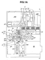
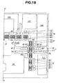
- FIGS 1A and 1B when combined, illustrate a diagrammatic plan view of an assembly shop for automotive vehicles implementing the present invention.
- the reference numeral A generally indicates a floor process unit (FPU).
- An interior parts mount process unit (IPMPU) B follows the FPU A.
- a body main process unit (BMPU) C follows the IPMPU B.
- a running parts mount process unit (RPMPU) D follows the BMPU C.
- An exterior parts attachment process unit (EPAPU) F follows the RPMPU D.
- IPMPU interior parts mount process unit
- BMPU body main process unit
- RPMPU running parts mount process unit
- EPAPU exterior parts attachment process unit
- the FPU A which will be further described later in connection with Figures 3 and 9, performs a process of producing a floor.
- Floor constituent parts are light metal die cast parts, respectively.
- an aluminum alloy is used in a standard casting process although a magnesium base alloy may be used as well. Workers assemble the floor constituent parts and a welding machine is used to securely connect them to produce a floor structure.
- the FPU A includes an assembly process unit (APU) 1 and a weld process unit (WPU) 3.
- the APU 1 includes a floor main process unit (FMPU) 5 and two sub-process units 7 and 9. Workers engage in jobs supporting each of the FMPU 5 and the sub-process units 7 and 9.
- the IPMPU B which will be further described later in connection with Figures 11 and 12, includes a rear floor module process unit (RFMPU) 11 and a rear end module process unit (REMPU) 13. Workers support each of the RFMPU 11 and REMPU 13.
- the IPMPU B also includes two manual lifts 4 in the neighborhood of the RFMPU 11 and REMPU 13, respectively, to assist worker(s) in transferring products to a main line. It further includes a dash module pallet 15, an engine room parts pallet 17, a carpet pallet 19, a rear sheet pallet 21, a console pallet 23, and a front sheet pallet 25. These pallets carry the parts. To assist worker(s) in transferring the parts to the main line, four manual lifts 4 are provided.
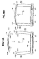
- the BMPU C which will be further described later in connection with Figures 14 and 15, includes a body side LH process unit (BSLHPU) 27, a roof process unit (RPU) 29, and a body side RH process unit (BSRHPU) 31.
- the BSLHPU 27 functions to produce a body side unit by trimming the interior of a body side structure.
- the BSLHPU 27 includes a body side sub-line inner trimming unit (BSSITU) 33, a body side set dolly 35, and a set of body side pallets 37.
- the body side pallets 37 and other pallets carry necessary parts for production of body side units. Workers support the BSSITU 33.
- the BSRHPU 31 functions to produce a body side unit by trimming the interior of a body side structure.
- the BSRHPU 31 includes a body side sub-line inner trimming unit (BSSITU) 39, a body side set dolly 41, and a set of body side pallets 43.
- the body side pallets 43 and other pallets carry necessary parts for production of body side units. Workers support the BSSITU 39.
- the RPU 29 includes a set process unit (SPU) 45, and a roof-reversing arm 47. Roof parts needed for different automobile types are carried by a plurality of pallets, namely, a small-sized (S-sized) sedan pallet 49, a small-sized (S-sized) tall pallet 51, a wagon pallet 53, a SS-sized commuter pallet 55, and a medium-sized (M-sized) sedan pallet 57.
- the BMPU C further includes a weld process unit (WPU) 58 where the assembled roof unit, body side units, and roof unit are fixedly secured by laser welding.
- WPU weld process unit
- Parts needed for trimming roofs having different widths and body sides are stored in pallets and located in a parts stock site 103. Theses pallets are supplied to sub-lines according to production order.
- the RPMPU D which will be further described later in connection with Figure 20, includes an automatic mounting machine 59 for mounting a body unit (UBU) to an under running unit (URU) 60 having been supplied to the line.
- UBU body unit
- UPU under running unit
- the EPAPU F follows the RPMPU D.
- the EPAPU F is followed by a liquid supply process unit (LSPU) G, a window attachment process unit (WAPU) H, a door mount process unit (DMPU) I, and an exterior surface decoration process unit (ESDPU) E.
- LSPU liquid supply process unit
- WAPU window attachment process unit
- DMPU door mount process unit
- ESDPU exterior surface decoration process unit
- the EPAPU F includes a rear bumper pallet 63, a front bumper pallet 65, a front end module pallet 67, and a lift 4 adjacent the front end module pallet 67 to assist a worker in conveying a front end module to the line.
- Workers draw a rear bumper from the pallet 63 and attach it to the rear end of the body unit. They draw a front bumper from the pallet 65 and attach it to the front end of the body unit. Using the lift 4, the workers mount a front end module to the body unit.
- the LSPU G includes a long life coolant supply station 68, a gasoline supply station 69, a brake oil supply station 71 and a power steering oil supply station 73. Necessary parts are provided at 72. A worker supply the vehicle with long life coolant, gasoline, brake oil and power steering oil.
- the WAPU H includes a lamp pallet 74 and a windshield panel pallet 75. Workers mount windshields to the body unit after drawing parts out of these pallets 74 and 75.
- the DMPU I which will be described later in connection with Figure 21, includes a right-hand door assembly process unit (RDAPU) 77, and a left-hand door assembly process unit (LDAPU) 78.
- RDAPU right-hand door assembly process unit
- LDAPU left-hand door assembly process unit
- Lifts 4 are provided adjacent to the RDAPU 77 and LDAPU 78, respectively. Workers support the RDAPU 77 and LDAPU 78. Using the lifts 4, workers can mount the door units out of the RDAPU 77 and LDAPU 78 to the body unit.
- the RDAPU 77 includes a sash module front pallet 79, a door mirror unit pallet 83, an interior trim module pallet 85, and an inner module pallet 87 around a roller conveyer 467 to make it easier for workers to assemble parts.
- the LDAPU 78 is substantially the same in construction as the RDAPU 77 so that the same reference numerals are used to designate like portions. Lifts 4 are provided adjacent the RDAPU 77 and LDAPU 78, respectively.
- the ESDPU E includes a roof pallet 89 for carrying a roof decoration plate of synthetic resin, a rear fender pallet 91 for carrying a rear fender decoration plate of synthetic resin, a front fender pallet 93 for carrying a front fender decoration plate of synthetic resin, a trunk lid pallet 95 for carrying a trunk lid decoration plate of synthetic resin, and a hood pallet 97 for carrying a hood decoration plate of synthetic resin. Workers draw the necessary decoration plates out of the pallets 89, 91, 93, 95, and 97 and attach them to the body unit.
- Parts needed by the above-mentioned process units A, B, C, D, F, G, H, I, and E are stocked at the adjacent sites 99, 101, 103, 105, 107, 109, and 111.
- a die casting process is used to make a light metal die cast part, which serves as one of floor constituent parts.
- molten light metal such as aluminum (Al) alloy and magnesium (Mg) alloy
- the floor constituent parts are made of aluminum alloy extrusion die cast products.
- the FPU A workers manually engage in assembling the floor constituent parts.
- a welding machine welds the assembled floor constituent parts to produce a floor structure.
- the IPMPU B the rear floor module, rear end module, dash module, engine room parts, carpet, rear sheet, console, and front sheet are mounted onto the floor structure to produce a floor unit (FU).
- the floor unit is conveyed to the BMPU C.
- the BSSITU 33 produces a left-hand body side unit that has been trimmed
- the BSSITU 39 produces a right-hand body side unit that has been trimmed.
- the body side set dolly 35 is used to transfer the left-hand body side unit to the left-hand side of the floor structure for attachment thereto.
- the body side set dolly 41 is used to transfer the right-hand body side unit to the right-hand side of the floor structure for attachment thereto.
- the roof-reversing arm 47 sets a roof unit for attachment to the upper ends of the body side units.
- a selected roof structure fit for type of vehicle is trimmed to produce a roof unit, and the roof unit is supplied to the roof-reversing arm 47.
- the automatic mounting machine 59 is used to mount an under running unit (URU) 60 to the body unit to produce a vehicle core.
- the under running unit 60 includes an engine, a power train, and a suspension.
- a rear bumper, a front bumper, a front end module, and etc. are attached to the vehicle core.
- LSPU G long life coolant, gasoline, brake oil, and power steering oil are fed to the vehicle core.
- DMPU H windshield panels are mounted to the vehicle core.
- DMPU I left-hand and right-hand door units are mounted to the vehicle core, Each of the door units has attached thereto a sash module front, a door mirror, an interior trim module, and an inner module.
- a roof decoration plate of synthetic resin, a rear fender decoration plate of synthetic resin, a front fender decoration plate of synthetic resin, a trunk lid decoration plate of synthetic resin, and a hood decoration plate of synthetic resin are attached to the vehicle core.
- An inspection line follows the EPDPU E.
- a painting process is no longer required. Thus, there is no need to alter painting equipment to cope with color switching. Assembling bodies can synchronize with assembling of vehicles. Stocks of bodies and parts associated therewith are greatly reduced, in number.
- a very compactor short vehicle assembly line is accomplished. This is because line length from the initiation of assembly of bodies to the completion of vehicles has been reduced to sixteen (16) processes from the conventional line length of about eight hundred (800) processes.
- the time required from the initiation of assembly of a body to the completion of a vehicle is greatly shortened. This makes it possible to shorten the time required from order to deliver.
- Conventional stock production can be replaced with order production. If order production is employed, stocks are greatly reduced, in number, thus resulting in a reduction in cost needed for transportation and stock control. Because the assembly line length for vehicle production can be greatly shortened, only a small area suffices for establishment of an assembly shop.
- Figure 2A illustrates a floor structure 113 on the assembly line immediately downstream of the FPU A.
- Figure 2B illustrates the floor structure 113 with a rear floor module 115 and a rear end module 117 on the assembly line immediately downstream of the RFMPU 11 and REMPU 13 of the IPMPU B.
- Figure 2C illustrates the floor structure 113 with a dash module 118, front sheets 119 and 121, and a rear sheet 123 on the assembly line immediately downstream of the IPMPU B to make a floor unit (FU).
- Figure 2D illustrates the FU with body side units (BSU) on the assembly line immediately downstream of the BSLHPU 27 and BSRHP 31 of the BMPU C.
- Figure 2E illustrates the FU with a roof unit (RU) on the BSUs on the assembly line immediately of the RPI 29 of the BMPU C.
- Laser welding in the WPU 58 fixedly secures the FU, BSUs and RU to each other to make a body unit (UBU).
- FIG. 2F illustrates the UBU with an under running unit (URU) 60 on the assembly line immediately downstream of the RPMPU D.
- the URU 60 includes an engine 131.
- Figure 2G illustrates the UBU with the URU 60 and also with door units 133, 137, windshield panels 149, 141, and liquid additives including engine brake oil, which is on the assembly line immediately downstream of DMPU I after the EPAPU F, LSPU G, and WAPU H.
- Figure 2H illustrates a vehicle off the assembly line immediately downstream of the ESDPU E, which vehicle has attached thereto a roof panel of synthetic resin 143, a rear fender panel of synthetic resin 145, a front fender panel of synthetic resin 147, a trunk lid panel of synthetic resin 149, and a hood panel of synthetic resin 151.
- FIG. 3 is a perspective view of the FPU A with its WPU 3 removed.
- the floor main process unit 5 and the sub-process units 7 and 9 have manual roller conveyers 153, 155, and 157, respectively.
- the floor main process unit 5 has three pallets 159, 161, and 163. These pallets 159, 161, and 163 are placed on load responsive extendable wheeled supports 173, 175, and 177, respectively.
- the sub-process unit 7 has one pallet 165 that is placed on a load responsive extendable wheeled support 179.
- the other sub-process unit 9 has three pallets 167, 169, and 171. These pallets 167, 169, and 171 are placed on load responsive extendable wheeled supports 181, 183, and 185, respectively. Each of the supports 173, 175, 177, 179, 181, 183, and 185 extends as weight of the pallet placed thereon decreases.
- the pellets 159, 161, and 163 are located near the site 101, and the pallets 165, 167, 169, and 171 are located near the site 99.
- workers manually deliver them to locations as illustrated in Figure 3 near the roller conveyer 153.
- workers deliver them to locations as illustrated in Figure 3.
- a pallet shooter incorporating wheel conveyer is used for smooth supply of a pallet carrying a relatively heavy part to an area with the reach of hands of a worker attending the assembly work.
- Each of the pallets 159, 161, and 163 has a plurality of shelves.
- a plurality of rear front floor constituent parts 195 are put on each of the shelves of the pallet 159.
- a plurality of middle front floor constituent parts 193 are put on each of the shelves of the pallet 161.
- a plurality of front floor constituent parts 191 are put on each of the shelves of the pallet 163.
- the pallet 165 has a plurality of shelves.
- a set of constituent parts of an engine compartment frame 187 is put on each of the shelves of the pallet 165.
- Each of the pallets 167, 169, and 171 has a plurality of shelves.
- Constituent parts of a rear floor frame 189 are put on shelves of the pallets 167, 169, and 171, respectively.
- removing a part from a shelf of one of them causes a reduction in the magnitude of load imparted to the associated support 173.
- This reduction causes the support 173 to extend to lift the next lower shelf to a level as high as the roller bearing 153. This greatly assists the worker in manually drawing the part from the pallet to the surface of the roller bearing.
- the workers move the extendable supports 173, 175, 177, 179, 181, 183, and 185 to the corresponding sites 101 and 99 and load the pallets with new parts.
- the FPU A realizes a cellular production line.
- the sub-process units 7 and 9 extend from the floor main process unit 5 to accomplish the cellular production. This makes it possible to simultaneously assemble all the constituent parts needed to complete a floor structure, avoiding a need to stock incompletely assembled portions of a floor structure.
- the sub-process unit 7 provides for manual assembly, on the roller conveyer 155, of parts needed to make the engine compartment frame 187.
- the sub-process unit 9 provides for manual assembly, on the roller conveyer 157, of parts needed to make the rear floor frame 189.
- the floor main process unit 5 provides for manual assembly, on the roller conveyer 153, of the front floor constituent parts 191, 193, and 195, the engine compartment frame 187 and rear floor frame 189.
- Each of the floor constituent parts is made of an aluminum alloy die cast part and low, in weight, enough for worker to handle. Thus, even women and/or aged people can engage in the assembly work.
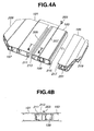
- Figure 4A illustrates the front, intermediate, and rear constituent parts 192, 193, and 195 of the front floor.
- Each of them is an aluminum alloy extrusion die cast product that has been made, in an extrusion die casting process, by forcing molten aluminum alloy through the mold cavity in a direction adapted to be parallel to a transverse direction of the vehicle.
- the front, intermediate, and rear constituent parts 192, 193, and 195 are formed with locate holes 197, 199, and 201, respectively.
- the front and intermediate constituent part 191 and 193 are formed with grooves 205 and 207 adapted to receive seat attachment brackets 203.
- the locate holes 197, 199, and 201 as well as the grooves 205 and 207 are formed in the die casting process.
- the front floor constituent part 191 is formed with a male coupling section 209. At a rear end, it is formed with a female coupling section 211. At a front end, the intermediate front floor constituent part 193 is formed with a male coupling section 213. At a rear end, it is formed with a female coupling section 215. At a front end, the rear front floor constituent part 195 is formed with a male coupling section 217. At a rear end, it is formed with a female coupling section 219.
- the male coupling section 213 engaged in the female coupling section 211
- the front floor constituent parts 193 and 191 are joined to each other.
- the female coupling section 217 engaged in the male coupling section 215, the front floor constituent parts 193 and 195 are joined to each other.
- the male and female coupling sections 213, 211, and the male and female coupling sections 215, 217 employ substantially the same structure. Referring to Figure 4B, and Figures 5A to 5C, the structure of the male and female coupling sections 213 and 211 is further described.
- the female coupling section 211 is formed with a positioning protrusion 223 on its bottom wall 221.
- the male coupling section 213 is formed with a positioning recess 225a on its leading or one end wall 225. Engagement of the protrusion 223 into the recess 225a prevents undesired rotation of the constituent part 193 in a direction to disengage from the constituent part 191.
- the female coupling section 211 has a groove that is defined by the bottom wall 221 and two spaced parallel flange inner walls 235 extending from the bottom wall 221.
- the inboard or upper flange extends further than the outboard or lower flange does to prevent transmission of noises to the vehicle cabin.
- Clips 227 are disposed near leading ends of the inner walls of the upper and lower flanges to define a mouth of the groove.
- the clips 227 protrude inwardly from the upper and lower flanges, respectively.
- the male coupling section 213 is formed with clip receiving recesses 229, which receive the clips 227, respectively.
- the male coupling section 213 is provided with surface portions 231, which come into close contact, over the whole area, with the flange inner walls 235, respectively, when the male coupling section 193 engages in the groove of the female coupling section 211.
- One of the surface portions 231 is located between the end wall 225 of the male coupling section 193 and one of the clip receiving recesses 229.
- the other of the surface portions 231 is located between the end wall 225 of the male coupling section 193 and the other of the clip receiving recesses 229.
- a worker Prior to coupling, a worker puts adhesive 233 in the clip receiving recess 229 of the male coupling section 193 near the vehicle cabin. As shown in Figure 5A, the worker engages the end wall 225 of the male coupling section 213 with the inboard and outboard clips 227 of the female coupling section 211. Then, the worker pushes the male coupling section 193 into the groove of the female coupling section 211 until the outboard clip 227 engages in the outboard recess 229 as shown in Figure 5B.
- the adhesive 233 provide a firm connection between the recess 229 of the male coupling section 213 and the inboard flange inner wall 235 of the female coupling section 211, and the surface portions 231 of the male coupling section 213 firmly engage the flange inner walls 235 of the female coupling section 211.
- the firm engagement with the flange inner walls 235 at the surface portions 231 and the adhesive 233 prevent passage of water and gas into the vehicle cabin.
- Coupling between the constituent parts 193 and 195 can be accomplished by engaging the male coupling section 215 in the female coupling section 217 in the same manner.
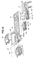
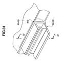
- Figure 6 illustrates an engine compartment frame 187, which serves as a constituent part of the floor.
- the engine compartment frame 187 is made of and dividable into four parts, namely, a dash lower cross member 237, a suspension mount member 239, a left-hand front side member 241, and a right-hand front side member, not shown.
- the dash lower cross member 237 is formed with a female coupling section 243 for receiving the male coupling section of the constituent part 191.
- the female coupling section 243 and the male coupling section 209 are substantially the same in structure as the female and male coupling sections 211 and 213, which have been illustrated in Figures 5A to 5C.
- the dash lower cross member 237 is formed with two upright spaced walls defining therebetween a groove 245, into which a lower end of a dash module may be inserted.
- the inboard side upright wall of the groove 245 is formed with two V-shaped cutouts 247. From each of the left and right ends thereof, the inboard side upright wall of the groove 245 is cut inwardly to form an end cutout 249.
- the dash lower cross member 237 is formed with a member coupling section 251, which the front side members 241 and the suspension member 239 are coupled with. Two through bores 253 are open at the upper surface of the coupling section 251.
- the front suspension member 239 is an aluminum alloy extrusion die cast product made by a die casting process in which molten aluminum alloy has been forced through a mold in a vertical direction viewing in Figure 6.
- the front suspension member 239 is provided with a coupling section for engagement with the member coupling section 251.
- Each of the front side members 241 is an aluminum alloy die cast produce made by a die casting process in which molten aluminum is forced through a mold in a direction along a longitudinal line of the vehicle viewing in Figure 6.
- a joint section 255 of an aluminum extrusion die cast product is attached, by welding, to the front end of each of the front side members 241.
- the provision of the joint sections 255 is to connect a front end module to the front side members 241.
- each of the front side members 241 is formed with a through hole 257.
- the left-hand and right-hand side members 241 are engaged with the member coupling section 251 at portions adjacent the ends of the suspension mount member 239.
- a bolt 258 is engaged into one of the through holes 253 and the through hole of the left-hand side member. Another bolt 258 is engaged into the other through hole 253 and the through hole of the right-hand side member. In this manner, the front side members 241 are provisionally connected to the dash lower cross member 237.
- the assembled engine compartment frame 187 is joined with the front floor constituent part 191 by engaging the male coupling section 209 in the female coupling section 243.
- the female coupling section 243 is provided with two clips 227 and a positioning protrusion 223.
- the female coupling section 243 and the male coupling section 209 are substantially the same in structure with the female and male coupling sections 211 and 213 illustrated in Figures 5A to 5C.
- FIGS 7A and 7B illustrate a rear floor frame 189, which serves as a constituent part of the floor.
- the rear floor frame 189 is made of and dividable into six parts, namely, a pair of rear side members (front) 261, a pair of rear side members (rear) 263, a rear cross member (front) 265, and a rear cross member (rear).
- the rear side members (front) 261 on the left-hand side and right-hand side are of symmetry in structure. They are given after cutting an aluminum alloy extrusion die cast product that is prepared by a die casting process in which molten aluminum alloy is forced through a mold in a direction along the longitudinal direction of the vehicle, viewing in Figure 7A.
- the rear cross member (front) 265 and rear cross member (rear) 267 are given after cutting an aluminum alloy die case product that is prepared by a die casting process in which molten aluminum alloy is forced through a mold in a direction along the vertical direction of the vehicle.
- Provisional connection between the rear cross member (front) 265, rear cross member (rear) 267, and left-hand and right-hand rear side members (front) 261 is made by locate pins, not shown, inserted through the locate holes 269.
- the rear cross member (front) 265 is also formed with a locate hole 271. Inserting the locate pins into the locate holes 269 and 271 results in the provisional connection of the rear cross member (front) 265 with the rear side members (front) 261.
- the provisional connection of the rear cross member (rear) 267 with the rear side members (front) 261 is made by the locate pins.
- the rear cross member (front) 265, rear cross member (rear) 267, and the rear side members 261 are fixedly interconnected by a laser weld.
- the rear side members (rear) 263 are connected to the rear side members (front) 261, respectively, by a bolt and nut connection.
- a ring nut 273 is fitted into the front end of each of the rear side members (rear) 263.
- the ring nut 273 is formed with four peripheral nut portions. This ring nut 273 within each of the rear side members (rear) 263 is inserted into a hole 275 formed at the rear end of the associated one of the rear side members (front) 261.
- the rear floor frame 189 which results from interconnecting the six parts as previously described, is provisionally engaged in the female coupling section 219 prior to transfer to the later described weld process.
- the amount of work load on each worker has been greatly reduced in provisionally assembling the parts to make a floor structure 113 due to use of aluminum alloy die cast parts.
- Each of the parts of aluminum alloy extrusion die cast product is about half, in weight, as compared to its counterpart of steel press product.
- Dies for die casting process are less expensive than dies for press process.
- Die casting parts made by die casting process using relatively inexpensive dies are not subjected to secondary operation, for example, bending operation, and they are provisionally connected one after another in assembly work to make a floor structure 113. Cost for the secondary operation can be saved.
- use of parts made by die casting process and molding instead of parts made by pressing process has resulted in a great reduction in investment on dies.
- each of the floor structure constituent parts which are made of dies casting products, fall within ranges easy to manipulate with.
- the maximum length is 1400 mm and the maximum weight is 10 kg.
- each of the coupling portions does not require a force greater than a manual force by workers during work to complete coupling between the adjacent two constituent parts due to snap action type clips.
- Figures 8A, 8B, and 8C are exploded views of three floor structures resulting from modifications made to cope with three different vehicle types.
- Figure 8A illustrates constituent parts of a standard floor structure.
- Figure 8B illustrates constituent parts of a floor structure to cope with a wide body type.
- Figure 8C illustrates constituent parts of a floor structure to cope with a long wheel base type.
- each of the constituent parts 191, 193, and 195 has a width L1, and the constituent part 193 has a length H1.
- each of the constituent parts 191, 193, and 195 has a width L2 wider than L1 although the constituent part 193 has the same length H1.
- each of the constituent parts 191, 193, and 195 has a width equal to L1, but the constituent part has a length H2 longer than H1.
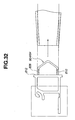
- the floor structure 113 resulting from provisional interconnection of the constituent parts is transferred by a manual roller conveyer 279 to the WPU 3.
- the WPU 3 is installed within a site that is kept off by two spaced partitions only one being indicated at 281.
- a motor driven shutter 283 is provided to close an entry to the site and another motor driven shutter 284 is provided to close an exit from the site.
- the motor driven automatic conveyer 285 is equipped with two parallel belts 295 and 297.
- the belts 295 and 297 extend over a base 293.
- the base 293 has therein a drive mechanism including a motor.
- the motor drives a drive roller 299.
- the belts 295 and 297 extend between the drive roller 299 and an idle roller 301.
- the laser weld robot 287 is located on one side of the conveyer 285.
- the locate unit 289 On each side of the conveyers 285, the locate unit 289 has a set of three locate pins 303, 305, and 307.
- the locate pins 303, 305, and 307 of each set which are on a support plate 309, can move along the adjacent side of the conveyer 285 for horizontal adjustment along the length of the belts 295 and 297 into alignment with the locate holes 197, 199, and 201 of the floor structure 113, respectively.
- the locate holes 197, 199, and 201 are subject to change in position depending upon a change in vehicle body type.
- the adjustment function of the locate pins 303, 305, and 307 ensures accurate alignment with the locate holes 197, 199, and 201.
- the support plates 309 are mounted to lifts 311, respectively, for vertical adjustment.
- the lifts 311 are supported on guide rails 312, respectively, for horizontal movement along the width of the belts 295 and 297.
- Each of the lifts 311 has a nut of a nut and screw mechanism 313. Turning the screw of one of the nut and screw mechanisms 313 adjusts the position of the associated lift 311 relative to the conveyer 285.
- accurate positioning of the locate pins 303, 305, and 307 relative to the locate holes 197, 199, and 201 is accomplished for the subsequent insertion into the locate holes 197, 199, and 201 to hold the floor structure 113 in an appropriate position on the conveyer 285.
- the work detector 291 is mounted to the conveyer 285 between the belts 295 and 297.
- the work detector 291 has a stop that can pivot upwards into abutting engagement with the engine compartment frame of the floor structure 113 on the conveyer 285 for detecting the floor structure 113 as well as positioning with regard to the work transfer direction.
- the work detector 291 Upon completion of weld operation by the laser weld robot 287, the work detector 291 causes its stop to pivot back to assume a horizontal rest position.
- the floor structure 113 is transferred manually along the roller conveyer 279 from the FMPU 5 to a position in front of the entrance of the WPU 3 where the motor driven shutter 283 is open.
- the belts 295 and 297 of the conveyer 285 start to move. What workers have to do is to push the floor structure 113 onto the belts 295 and 297. Then, the conveyer 285 pulls the floor structure 113 into the site where the robot 287 is.
- the drive roller 299 stops its operation to bring the belts 295 and 297 into a standstill, and then the locate pins 303, 305, and 307 are inserted into the locate holes 197, 199, and 201. In this manner, the floor structure 113 is held in the appropriate position for the subsequent welding operation by the laser weld robot 287.
- the shutter 283 is closed upon or after completion of the operation to hold the floor structure 113.
- the laser weld robot 287 is put into operation to perform a so-called "one-direction" weld by laser beam.
- the term "one-direction" weld is herein used to mean a weld operation to accomplish a weld between two members by concentrating energy beam to a weld point in one-direction.
- a laser beam is concentrated to a weld point in one-direction.
- the locate pins 303, 305, and 307 are lifted together with the floor structure 113 and work detector 291, holding the lower surface of the front floor constituent parts 191, 193, and 195 above the level of the belts 295 and 297,
- the laser weld robot 289 concentrates a laser beam on the lower surface of the constituent parts 191, 193, and 195 to accomplish weld between them.
- MIG welding and friction welding are alternative to the laser welding.
- the locate pins 303, 305, and 307 are lowered to put the floor structure 113 on the belts 295 and 297.
- the stop of the work detector 291 is pivoted back to the horizontal stored position.
- the locate pins 303, 305, and 307 disengage from the locate holes 197, 199, and 201.
- the shutter 284 is lifted to open the exit.
- the belts 295 and 297 starts to move to transfer the floor structure toward the next IPMPU B where the interior parts, such as seats, are mounted to the floor structure 113.
- FIG. 10 illustrates such coupling with a welding portion indicated at 315. Specifically, the leading end of the outboard flange adjacent the outboard clip 227 is welded to the outer wall adjacent the clip receiving recess 229 of the male coupling section
- the welding operation is carried out within the site that is kept off by the partitions, thus ensuring the safety of workers.
- the laser weld robot 287 is able to automatically locate where welding operation are needed and conducts welding operations there.
- the locate unit 289 cooperates with the laser weld robot 287 to control relative location among the constituent parts of the floor structure 113 during the welding operation. Thus, welding operation can be performed with excellent accuracy.
- the IPMPU B includes the RFMPU 11 and the REMPU 13.
- the RFMPU 11 includes a roller conveyer 317. Near one end of the roller conveyer 317, a pallet 321 is arranged.
- the pallet 321 stores rear floor panels 319 and mounted to a wheeled load responsive extendable support 323.
- the pallet 325 is mounted to a wheeled load responsive extendable support 327 and stores spare tires.
- the pallet 329 stores tire pans and floor carpets.
- the pallet 331 stores jacks.
- a manual lift 4 is arranged to assist worker in transferring a rear floor module to the main assembly line of the IPMPU B.
- a worker pulls a rear floor panel 319 out of the pallet 321 onto the roller conveyer 317.
- the worker pulls a tire, a tire pan, a floor carpet, and a jack out of the pallets 325, 329, and 331 for attachment to the rear floor panel 319 to produce a rear floor module 115,
- the worker transfers the rear floor module 115 to the main line of the IPMPU B.
- the load responsive extendable supports 323 and 327 are the same in construction and operation as the load responsive extendable supports 173, 175, 177, 179, 181, 183 and 185 shown in Figure 3.
- the REMPU 13 includes a roller conveyer 333.
- the roller conveyer 333 includes two spaced belts 333a and 333b, which are arranged on different levels to support a rear end panel 335, Near one end of the roller conveyer 333, a pallet 337 is arranged.
- the pallet 337 stores rear end panels 335.
- the pallet 337 is mounted to a wheeled load responsive extendable support 339 for vertical movement. It also moves in a transverse direction of the conveyer 333, making it easier for a worker to pull a rear end panel 335 out of the pallet 337 onto the conveyer 333. If the pallet 337 becomes empty, a worker can move the pallet 337 on the wheeled load responsive extendable support 339 to the site 99 for supplement.
- a pallet 341 is arranged, which stores trunk room finishers. Near the other side of the roller conveyer 333, two pallets 343 and 345 are arranged. The pallet 343 stores a plurality piece of seal rubber. Near the other end of the roller conveyer 317, a manual lift 4 is arranged to assist worker in transferring a rear end module to the main assembly line of the IPMPU B. If empty, the pallets 341, 343 and 345 are filled up with new parts at the site 99.
- a worker pulls a rear end panel 335 out of the pallet 337 onto the roller conveyer 333. Moving the rear end panel 335 along the roller conveyer 333, the worker pulls a trunk room finisher, a seal rubber and the like out of the pallets 341, 343, and 345 for attachment to the rear end panel 335 to produce a rear end module 117. Using the manual lift 4, the worker transfers the rear end module 117 to the main line of the IPMPU B.
- the rear floor module 115 is mounted to the rear floor frame 189 from the above and securely fixed thereto by bolt and nut connection. At rear end portions 117a, the rear end module 117 is fixedly secured, by bolt and nut connections, to rear end flanges 189a of the rear side members (rear) 263 of the rear floor frame 189. The rear end module 117 is fixedly secured to appropriate portions of the rear floor module 115.
- the dash module 118 is inserted into the groove 245 of the engine compartment frame 187 of the floor structure 113. Via the V-shaped cutouts 247, a center console 118b extends into the vehicle cabin. Via the end cutouts 249, dash sides 118a project into the vehicle cabin.
- the front seats 119 and 121 are attached to the brackets 203 engaged in the grooves 205 and 207 of the front floor constituent parts 191 and 193.
- the brackets 203 have been inserted from open ends of the grooves 205 and 207 inwardly to predetermined positions. Using a proper jig, not illustrated, the brackets 203 are appropriately positioned.
- the rear seat is attached to the floor structure 113 in the similar manner. In this manner, a floor unit FU is made.
- a worker can mount the interior parts, such as the seats 119 and 121, to the floor structure 113 in an open space.
- the worker is no longer required to engage in hard labor within a confined closed space within a vehicle body shell. This results in a considerable increase in productivity.
- a worker transfers the floor unit FU by a roller conveyer to the BMPU C.
- Figure 14 is a general perspective view of the BMPU C, illustrating a main line and the BSLHPU 27, which is arranged on one side of the main line.
- the BSRHPU 31, not illustrated, is arranged on the other side of the main line.
- the BSRHPU 31 is substantially the same as the BSLHPU 27.
- the BSLHPU 27 includes a body side pallet 37, a roller conveyer 349 of the BSSITU 33, a pallet 351 that stores inner trimming parts, and a body side set dolly 35.
- the body side pallet 37 has stored in partitioned sections different body side structures 348 for a medium (M) class wagon, a height wagon, a wagon, and a small (S) sedan.
- the body side pallet 37 is provided with a roller conveyer for facilitating supply of the body side structure 348.
- the body side pallet 37 is supported on a traverse shifter 355. Thus, it can move until a required body side structure 348 is exposed for facilitating manual operation to pull the required body side structure 348 to the roller conveyer 349.
- the body side set dolly 35 is a roller conveyer 359 equipped with wheels 357.
- a worker selects a body side structure 348, which is to be trimmed, by sliding the pallet 37 and draws it onto the roller conveyer 349.
- the worker takes out an assist grip, a seat belt unit, a pillared trim and the like from the pallet 351 and attaches them to the body side structure 348 on the roller conveyer 349, producing a body side unit BSU.
- the attachment work is performed in an open space, resulting in increased assembly efficiency.
- the body side unit BSU is transferred to the body side set dolly 35.
- the body side unit BSU is provisionally connected to the floor unit FU on the main line. This provisional connection is accomplished by inserting locate pins into locate holes. With this connection, accurate positioning of the body side unit BSU relative to the floor unit FU is also achieved.
- the left-hand and right-hand body side units BSU are provisionally connected to the floor unit FU in the manner as described above.
- a roof unit RU is connected to the body side units BSU.
- the roof unit RU is produced by the SPU 45.
- a roof structure appropriate to a vehicle body type is trimmed with interior parts to provide a roof unit RF, and the roof-reversing arm 47 reveres the roof unit RF to its normal position.
- the roof unit RF is lowered to the body side units BSU as shown in Figure 14.
- a ceiling crane 363 carries the roof unit RF to a position over the roller conveyer 361 of the main line, and lowers the roof unit RF for provisional connection with the body side units BSU. This provisional connection is accomplished by inserting locate pins into locate holes.
- the body assembly is transferred to the WPU 58 where, in the same manner as described referring to Figure 9, a laser welding is carried out automatically to produce a body unit UBU.
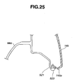
- FIG 15 is a fragmentary perspective view of the RPU 29 illustrating how the roof unit RU is supplied to the roller conveyer 361 of the main line.
- the RPU 29 includes the SPU 45.
- the SPU 45 includes a work stand equipped with a recessed roller conveyer 365. At a portion near a leading end, the roller conveyer 365 is fixedly connected to a rotary shaft 367 that is supported for rotation about its axis.
- a cylinder type lift 369 is operatively connected to a portion near a trailing end of the roller conveyer 365.
- the roller conveyer 365 can pivot about the axis of the rotary shaft 367 as the cylinder type lift 369 lifts the trailing end.
- a chute 373 is provided with a roller conveyer 371 and extends from the site 103 down to the SPU 45 to supply a roof structure 375 fit for a vehicle body type.
- Pallets are arranged around the SPU 45 and store different interior parts for different vehicle body types, respectively.
- Figure 15 illustrates a pallet 53 storing an interior part for wagon 376 and a pallet 57 storing an interior part for M sedan 378.
- a roller conveyer 377 is associated with the pallet 53 to facilitate manual transfer of the part to the SPU 45.
- a roller conveyer 379 is associated with the pallet 57 to facilitate manual transfer of the part to the SPU 45.
- the roof-reversing arm 47 includes a stand section 381 and an arm section 383.
- the ceiling crane 385 is installed to transfer the roof unit RU from the arm section 383 to the roller conveyer 361 of the main line.
- the ceiling crane 385 includes a rail 387 fixed relative to the ceiling and a wheeled shifter 389 that is automatically movable along the rail 387.
- the shifter 389 can grip the roof unit RU and transfer it to a predetermined portion above the roof conveyer 361 of the main line.
- the chute 373 supplies roof structures 375 to the SPU 45.
- the SPU 45 supports a roof structure 375 for wagon, while the roof-reversing arm 47 has a roof unit RU for sedan.
- a worker selects a roof interior part for wagon 376 and transfers it onto the roof structure 375 on the SPU 45 along the roller conveyer 377 for attachment to the roof structure 375.
- the worker presses an activation button. Pressing the activation button causes the cylinder type lift 369 to extend to elevate the trailing end of the roller conveyer 365, thus providing a slope.
- the roof unit RU is transferred to the stand 381.
- the arm section 383 reverses the roof unit RU on the stand 381 to a position as illustrated in Figure 15 in connection with the roof unit RU for sedan.
- the wheeled shifter 389 grips the roof unit RU having been reversed by the roof-reversing arm 47 and moves along the rail 387 to the predetermined position above the roller conveyer 361 of the main line. Then, the roof unit RU is provisionally connected to the body side units BSU connected to the floor unit FU for wagon.
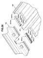
- Figure 16 illustrates where a floor unit FU, a body side unit BSU, and a roof unit RU are positioned relative to each other as well as structures for positioning.
- the floor unit FU is provided with two locate holes 197 and 199, while the body side unit BSU has two locate pins 391 and 393.
- These locate pins 391 and 393 are made of steel pipes embedded into a body side structure 348 of aluminum die cast.
- the pins 391 and 393 may be integral parts of the body side structure 348.
- the locate pins 391 and 393 and the locate holes 197 and 199 constitute a lower structure for positioning a lower portion of the body side unit BSU to the floor unit FU.
- the locate pin 391 is disposed at a point below a front pillar 395 of the body side unit BSU.
- the locate pin 393 is disposed at a point below a center pillar 397 within an area where the center pillar 397 and a side sill 398 are joined.
- the lower structure is arranged in a level lower than a lower end of the center pillar 397.
- the locate pins 391 and 393 and the locate holes 197 and 199 have their axes, respectively, and they are arranged with their axes lying in a traverse direction with respect to a longitudinal direction of the vehicle body.
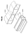
- the positioning and the provisional connection between the roof unit RU and the body side unit BSU are accomplished by cooperation of locate pins with locate holes, respectively.
- the body side unit BSU is formed with three locate holes 401, 403 and 405.
- the roof unit RU has three locate pins 413, 415 and 417.
- the locate hole 401 is disposed at an upper end of the front pillar 395.
- the locate hole 403 is disposed at an upper end of the center pillar 397.
- the locate hole 405 is disposed at an upper end of a rear pillar 399.
- the locate pin 413 is disposed at a lower end of a front pillar 407 of the roof unit RU.
- the locate pin 415 is disposed at an upper end of a center pillar 409 of the roof unit RU.
- the locate pin 417 is disposed at an upper end of a rear pillar 411 of the roof unit RU.
- the locate pins 413, 415 and 417 and the locate holes 401, 403 and 405 constitute an upper structure for positioning the roof unit RU to an upper portion of the body side unit BSU.
- the upper structure is composed of at least a portion disposed at the upper end of the center pillar 397, 409 and a portion disposed at a mid point of the front pillar 407, 395.
- Figure 16 illustrates the connections between the left-hand body side unit BSU, the floor unit FU, and the roof unit RU, only.
- the connections between the right-hand body side unit BSU, the floor unit FU, and the roof unit RU are substantially the same.
- the locate pins 413, 415 and 417 and the locate holes 401, 403 and 405 have axes.
- the locate pins 413, 415 and 417 and the locate holes 401, 403 and 405 are arranged with their axes lying in a vertical direction with respect to the vehicle body.
- the axis of the locate pin 403 of the upper structure and that of the locate pin 391 of the lower structure are disposed in a common vertical plane of the vehicle body.
- the axis of the locate pin 415 of the upper structure and that of the locate pin 393 of the lower structure are disposed in another common vertical plane of the vehicle body.
- the locate pin 413 of the roof unit RU is disposed at where the front pillar 407 and a hood ridge 408 are joined.
- the locate pin 415 is disposed where the center pillar 409 and a roof side rail 410 are joined.
- the locate pin 417 is disposed where the rear pillar 411, a rear roof rail 412, and a roof side rail 410 are joined.
- each of the body side units BSU joins the floor unit FU inwardly in a transverse direction with respect to the longitudinal line of the vehicle body.
- the roof unit RU is lowered in a vertical direction to join the two body side units BSU that has previously been connected to the floor unit FU by inserting the locate pins 413, 415 and 417 into the locate holes 401, 403 and 405.
- the upper positioning structure holds upper free edges of the body side units BSU that are connected to the floor unit FU, thus further enhancing accuracy in connection of the body side units BSU to the floor unit FU.
- Positioning and provisional connection between floor unit FU, body side units BSU, and roof unit RU are accomplished by the pins and locate holes without any help of a vehicle body holding jig. Thus, such a jig may no longer be needed. If floor units and roof units have different widths, there is no need to prepare different jigs for different body widths. This results in a great reduction in the amount of equipment investment to the process of vehicle body build-up.
- provisionally connecting the body side unit BSU to the floor unit FU accomplishes positioning.
- the roof unit RU serves as a jig to produce a well-built vehicle body.
- the locate hole 199 of the floor structure 113 has an inner diameter unaltered because the floor structure 113 is of the aluminum alloy die casting product. Because the inner diameter of the locate hole 199 cannot be altered, the pin 393 of the body side unit BSU is modified for adjustment of the provisional connection.
- the pin 393 is reduced in diameter.
- the reduced diameter free end 393a gradually increases its diameter toward the body side unit BSU, forming a conical spherical taper surface 393b, to connect smoothly into a shank with an unreduced diameter.
- the reduced diameter free end 393a and the adjacent taper surface 393b are provided to facilitate insertion of the pin 393 into the locate hole 199.
- appropriately selecting the coupling length L and the clearance ⁇ can control the deviation S without any help of a jig.
- Figure 18A illustrates the position of the body side units BSU before engagement with the roof unit RU
- Figure 18B illustrates the position of the body side units BSU after engagement with the roof unit.
- Each of the pins 393 of the lower positioning structure is inserted into the locate hole 199 in horizontal direction
- each of the pins 415 of the upper positioning structure is inserted into the locate hole 403 in vertical direction. This connecting structure reduces the angle ⁇ further toward zero.
- the structural rigidity of the vehicle body may be increased more by providing contact surfaces, one on each of the body side units BSU and the other on the adjacent sides of the roof unit RU as well as ribs to suppress local deformation in cross sectional profile.
- the pin 393 inserted into the locate hole 199 which is used for connection between the floor unit FU and the body side unit BSU, is fixedly attached to the body side unit BSU at an area where the center pillar 397 and the side sill 398 join with each other.
- the pin 413 inserted into the locate hole 401 which is used for connection between the body side unit BSU and the roof unit RU, is fixedly attached to the roof unit RU at an area where the hood ridge 408 and the front pillar 407 join with each other.
- the above-mentioned areas are reinforced locally to provide a vehicle body, which exhibits excellent performance in protecting vehicle occupants during collision as well as increased structural rigidity.
- the pins 391, 393, 413, 415 and 417 are fixedly attached to the body side unit BSU or the roof unit RU and inserted, with an appropriate clearance, into the locate holes 197, 199, 401, 403 and 405, respectively.
- This pin and hole connections facilitate wide distribution of stress imparted to the vehicle body over the whole area of the vehicle body. This is because all of interface surface areas between the pins 391, 393, 413, 415 and 417 and the locate holes 197, 199, 401, 403 and 405 bear the stress. Accordingly, structural strength and rigidity of a vehicle body are maintained sufficiently high without any reinforcement.
- the assembled body unit UBU is transferred to the WPU 58 (see Figure 15).
- the WPU 58 they are fixedly connected to each other by laser welding.
- the laser welding is carried out by an automatic robot and within a site defined between two spaced partitions in the same manner as the welding process to produce the floor unit FU.
- the interior parts such as seats and instrument panel, are mounted within the body unit UBU. It is impractical to carry out a spot welding mainly due to difficulty of inserting a spot gun into the interior of the body. Thus, welding from the outside of the body is recommended to fixedly connect the floor unit FU, body side units BSU and roof unit RU.
- the floor structure 113 of the floor unit FU employs a dual floor structure so that an inner plate 419 of the floor structure 113 and a protrusion 421 of the body side unit BSU need to be fixedly connected.
- Normal temperature thermosetting adhesive 423 fills the interface between the inner plate 419 and the protrusion 421 to bond therebetween.
- An outer plate 425 of the floor structure 113 and a bracket 427 of the body side unit BSU are fixedly connected to each other at 429 by laser welding. Heat generated by the laser welding is transmitted through the floor structure 113 toward the interior parts already mounted to the vehicle cabin.
- An air layer between the inner and outer plates 419 and 425 of the dual floor structure effectively reduce the transmission of such heat, causing no heat damage.
- the adhesive 423 fills and seals any clearance between the inner plate 419 and the protrusion 421 to prevent any passage of air and water at an excellent level, thus eliminating a need of another sealing arrangement.
- thermosetting seal which is cured during baked finish, is used for a vehicle body in the conventional vehicle production. Such baked finish has not been used, making it impossible to use such high temperature thermosetting seal. Thus, a need has arisen to use normal temperature thermosetting adhesive at 423.
- Figure 19 illustrates structure around the pin 417 of the rear pillar 411 of the roof unit RU inserted into the locate hole 405 through the rear pillar 399 of the body side unit BSU. As shown in Figure 19, the rear pillar 411 of the roof unit RU is welded, by laser welding, to the rear pillar 399 of the body side unit BSU at 429.
- the flanges 430A and 430C are welded, by laser welding, to the body side unit BSU and the roof unit RU, respectively, to provide the closed sectioned structure reinforcing the roof side rail 410 (see Figure 16).
- the preceding description now clearly indicates that laser welding between the flange 430A of the roof unit RU and each of the body side unit BSU and between the flange 430B of each of the body side unit BSU and the roof unit RU completes a closed cross section structure. This structure reinforces the connection between the roof unit RU and each of the body side units BSU.
- the inner trimming is temporarily removed to expose a clearance between each of the protrusions 421 of the body side units BSU and the inner plate 419 (see Figure 17) of the floor unit FU. Subsequently, the adhesive is put into the exposed clearances.
- the inner trimming is temporarily removed to expose overlapped portions between the flanges 430C of the body side units BSU and the portions 430D (see Figure 18A). Subsequently, these overlapped portions are welded by laser welding. In this manner, good appearance of the interior of the vehicle cabin is maintained. Finally, these temporarily removed trimming parts are mounted again. Such parts to be temporarily removed should be as small as possible to cover only the adhesive and welding connections to avoid any delay work in connecting the vehicle body parts to each other.
- the body unit UBU that has been welded by laser welding operation at the WPU 58 is transferred to the RPMPU D where the body unit UBU and the under running unit URU 60 are joined.
- the RPMPU D includes two automatic conveyers 431 and 433.
- the automatic conveyer 431 extends on downstream side of the WPU 58 (see Figure 14).
- This automatic conveyer 431 is substantially the same as the automatic conveyer 285 illustrated in Figure 9 and includes a pair of parallel belts 435, which are driven by a motor under a controller.
- a power-assisted lift 437 is arranged near the downstream end of the automatic conveyer 413.
- This lift 437 includes a platform supported by extendable cylinders 439. Activating the cylinders 439 lifts the platform of the lift 437.
- the other automatic conveyer 433 is arranged downstream of the automatic conveyer 431. Similarly, the automatic conveyer 433 includes a pair of parallel belts 441, which are driven by a motor under a controller.
- the automatic mounting machine 59 On one side of the automatic conveyers 431 and 433, the automatic mounting machine 59 is installed.
- the automatic mounting machine 59 include a rail 443.
- the rail 443 is supported and can be elevated by a lift 445.
- a wheeled shifter 447 for gripping a body unit UBU is supported by and movable along the rail 443. Three typical positions which the wheeled shifter 447 may take are illustrated in Figure 20.
- the wheeled shifter 447 has a first position above the platform of the lift 437. If the lift 445 lowers the rail 343 and the wheeled shifter 447 down to a position where the wheeled shifter 447 can grip an upper body UBU on the platform of the lift 437, the wheeled shifter 447 grips the body unit UBU.
- the lift elevates the rail 443 together with the wheeled shifter 447 gripping the body unit UBU.
- the wheeled shifter 447 moves along the rail to a second position above an under running unit URU 60.
- the rail 443 is lowered again down to a position where the upper vehicle body UBU can be operatively connected to the under running unit URU 60.
- the rail 443 and the wheeled shifter 447 are elevated again.
- the wheeled shifter 447 moves from the second position to a third position above the automatic conveyer 433.
- the rail 443 and the wheeled shifter 447 are lowered again and the wheeled shifter 447 releases the main body MB.
- the rail 443 and the wheeled shifter 447 are elevated again leaving the main body MB on the automatic conveyer 433.
- the wheeled shifter 447 moves back to the first position again.
- An URU supply unit 61 includes a pair of automatic conveyers 449 and 451 extending from the site 105 where under running units URU are stationed. It also includes a ball roller table 453, a roller conveyer 455, and pallets 459 and 461.
- Each of the automatic conveyers 449 and 451 is equipped with a pair of belts 457.
- the automatic conveyer 449 transfers the pallet 459 having an under running unit URU 60, while the automatic conveyer 451 transfers the empty pallet 461.
- Each of the pallets 459 and 461 is provided with set pins 463.
- Each pallet 459 or 461 is equipped with a set of four guide rollers 464 at corners thereof, respectively. The guide rollers of each pallet can rotate about vertical axes, respectively.
- the ball roller table 453 is disposed between the automatic conveyers 449 and 451.
- the roller conveyer 455 transfers the pallet 459 or 461 from the ball roller table 453 to a guide rail 456 and vice versa.
- the guide rail 456 extends from the roller conveyer 455 to a location between the automatic conveyers 431 and 433. Along this guide rail, the pallet 459 is transferred to a predetermined position between the automatic conveyers 431 and 433. The empty pallet 461 is transferred back to the roller conveyer 455.
- the guide rail 456 has a pair of channel shaped rails 465, which are spaced with their openings opposed to each other.
- the guide rail 456 has stops 468 near remotest ends of the rails 465 from the roller conveyer 455.
- the automatic conveyer 431 transfers the body unit UBU from the WPU 58.
- a sensor detects that the body unit UBU has reached a position above the platform of the lift 437 and activates the cylinders 439.
- the cylinders 439 extend to lift the platform to hold the body unit UBU free from the automatic conveyer 431.
- the rail 443 of the automatic mounting 59 is lowered.
- the wheeled shifter 447 grips the body unit UBU on the platform of the lift 437.
- the lift 445 elevates the rail 443.
- the wheeled shifter 447 moves from the first position along the rail 443 in a downstream direction to the second position above the guide rail 456 of the URU supply unit 61.
- An under running unit URU is transferred from the parts station site 105 (see Figures 1A and 1B).
- the under running unit URU includes an engine, a power train, a suspension system, and a fuel supply system.
- a pallet 459 is selected in accordance with a production order out of different pallets having different under running units.
- the automatic conveyer 449 transfers the selected pallet 459 toward the ball roller table 453 as shown in Figure 20.
- the automatic conveyer 449 can set the pallet 459 on the ball roller table 453. Workers manually moves the pallet 459 with the under running unit URU from the ball roller table 453 to the guide rail 456 via the roller conveyer 455.
- the workers move the pallet 459 along the guide rail 456 to a predetermined position between the automatic conveyers 431 and 433. Movement of the pallet 459 beyond this predetermined position is limited by the stop 468.
- the guide rollers 464 are in rolling contact with the channel shaped rails 465 for smooth movement of the pallet 459.
- Worker initiate operations to operatively interconnect the body unit UBU and the lower running unit URU.
- the workers can perform these operations at a level as high as the vehicle main body MB, eliminating such an operation that forces a worker to lie on its back. This results in great enhancement in working environment.
- the lift 445 elevates the rail 443 again to the elevated position. Then, the wheeled shifter 447 with the main body MB moves in the downstream direction toward the third position above the automatic conveyer 433. After reaching the third position above the automatic conveyer 433, the rail 443 is lowered by the lift 445 and the wheeled shifter 447 releases the main body MB to set it on the automatic conveyer 433. The lift 445 elevates the rail 443 again to the elevated position.
- the empty wheeled shifter 447 moves in an upstream direction toward the first position above the platform of the lift 437 of the automatic conveyer 431.
- the automatic conveyer 433 transfers the main body MB to the next EPAPU F where exterior parts are attached to the main body MB.
- the empty pallet is moved back along the guide rail 456 to the roller conveyer 455.
- the empty pallet is moved back via the ball roller table 453 to the automatic conveyer 451.
- the automatic conveyer 451 returns the empty pallet 461 to the parts station site 105.
- a new under running unit URU is set on the pallet 461.
- a rear bumper from the rear bumper pallet 63, a front bumper from the front bumper pallet 65, and a front end module from the front end module pallet 67 are attached to the main body MB.
- the main body MB is on a roller conveyer and manually moved along the roller conveyer.
- the front-end module includes a radiator, a condenser, headlamps, and a bracket structure.
- the front-end module is heavy.
- the lift 4 is therefore used to mount it to the main body MB.
- the rear bumper and front bumper are not heavy so that workers can manually carry them to the main body MB for attachment thereto.
- workers transfer the main body MB toward the LSPU G using the roller conveyer.
- the worker supplies the main body MB with long life coolant from the long life coolant supply station 68, gasoline from the gasoline supply station 69, brake oil from the brake oil supply station 71, and power steering oil from the power steering oil supply station 73.
- workers transfer the main body MB toward the WAPU H using the roller conveyer.
- a right-hand door unit is assembled in the RDAPU 77 and a left-hand door unit is assembled in the LDAPU 78.
- a worker mounts the door units to the main body MB.
- a white body has door panels and is subjected to painting and coating processes. After completion of the painting and coating processes, the door panels are removed and equipped with necessary parts to provide door units. Then, the door units are mounted to the body again.
- the preferred implementation of the present invention does not employ painting and coating processes. Thus, such complicated work is no longer required to mount doors to the vehicle body.
- FIG 21 illustrates the RDAPU 77.
- the LDAPU 78 is substantially the same as the RDAPU 77 except a minor difference that a left-hand door unit is assembled in the LDAPU 78, while a right-hand door unit is assembled in the RDAPU 77.
- the RDAPU 77 includes the roller conveyer 47.
- the sash module front pallet 79, inner module pallet 87, interior trim module pallet 85 and door mirror unit pallet 83 are arranged around the roller conveyer 467.
- the sash module pallet 79 is set on a load responsive extendable wheeled support 477.
- the pallet 469 carries a number of sash modules, which number may vary. Thus, the magnitude of weight applied to the support 477 may vary. However, the load-responsive wheeled support 477 extends in response to a reduction in weight applied thereto to hold the pallet 469 at a level as high as the roller conveyer 467.
- a door sash module 479 is transferred from the pallet 79 onto the roller conveyer 467. Moving the door sash module 479 along the roller conveyer 467, an. inner module 481, an interior trim module 483. and a door mirror unit 485 are attached to the door sash module 479 to produce a door unit.
- the lift 4 see Figure 1B
- the door unit is supplied by worker to the main line and attached to the main body MB on the main line.
- the main body MB is transferred to the ESDPU E.
- a worker draws roof resin panels 143 out of the roof pallet 89 and attaches them to the main body MB.
- the worker draws rear fender resin panels 145 out of the rear fender pallet 91 and attaches them to the main body MB.
- the worker draws front fender resin panels 147 out of the front fender pallet 93 and attaches them to the main body MB.
- the worker draws a trunk lid resin panel 149 out of the trunk lid pallet 95 and attaches it to the main body MB.
- the resin panels are classified in accordance with a production schedule and then supplied to the pallets 89, 91, 93, 95 and 97.
- the main body MB is simplified by eliminating unnecessary portions and parts.
- the roof resin panels 143 are mounted in roof openings 491 and 493, respectively.
- the rear fender resin panels 145 are mounted to the outer surfaces of the rear fenders 497 of the main body MB.
- the front fender resin panels 147 are mounted to the outer sides of the hood ridges 408, respectively.
- the trunk lid resin panel 149 is attached to a trunk lid inner 503 and mounted to the main body MB together with the trunk lid inner 503.
- the trunk lid inner 503 is made of an aluminum die cast product.
- the hood resin panel 151 is attached to a hood inner 507 and mounted to the main body MB together with the hood inner 507.
- the hood inner 507 is made of an aluminum die cast product.
- door resin panels 509 and 511 are attached to a front door unit 513 and a rear door unit 515, respectively.
- Figures 23, 24 and 25 illustrate structures via which the resin panels are attached to the main body MB.
- FIG 23 illustrates the roof resin panel 143 fit in the roof opening 491.
- the roof resin panel 143 has integral clip portions, only one being shown at 143a, which engage in coupling holes, only one being shown at 491a, respectively.
- the roof opening 491 is defined by and surrounded by an edge portion 491b.
- the edge portion 491b is thicker than its surrounding recessed portion and it is formed with the coupling holes 491a. The thickened edge portion 491b comes into firm engagement with the adjacent inner surface portion of the roof resin panel 143 when the clip portions 143a engage in the coupling holes 491a, respectively.
- the roof resin panel 143 has an integral dam 143b downwardly protruding from the inner surface thereof.
- the dam 143b is disposed in the proximity of the outer periphery of the roof resin panel 143, and the clip portions 143a are remoter from the outer periphery of the roof resin panel 143 than the dam 143b is.
- the dam 143b comes into firm engagement with the recessed surrounding portion of the thickened edge portion 491 when the clip portions 143a engage in the coupling holes 491a, respectively.
- Sealing material 517 fills in a space between the dam 143b and the thickened edge portion 491.
- a protrusion 143c on the periphery extends over the overall periphery. This protrusion 143c is used to hold a weather strip 519 in position.
- the weather strip 519 is disposed within a recess defined by the recessed surrounding portion between the roof side rail 410 and the outer periphery of the roof resin panel 143.
- the sealing material 517 is in the neighborhood of the hooked portions 143a, thus keeping enhanced gas tight and liquid tight seal of the vehicle cabin.
- the provision of the weather strip 519 makes much contribution to enhancement of outward appearance and of seal effectiveness.
- the front fender resin panel 147 is fixedly connected to the hood ridge 408 by mechanical fasteners, such as a bolt 520 with a nut.
- the bolts and nuts have undergone process for rust prevention.
- the front fender resin panel 147 has a curved portion 147a.
- a lower edge portion of the rear fender resin panel 145 is fixedly connected to a wheelhouse opening defining edge 521 of the body side unit BSU by means of resin clips, only being shown at 523.
- the front fender resin panel 145 has a curved portion 145a.
- each of the resin panels 143, 145, 147, 149 and 151 may be accomplished by any one of or any combination of the integral clips, mechanical fasteners, such as, bolts and nuts, and resin clips.
- the integral clips accomplish the attachment of the resin panel 143
- the bolts and nuts accomplish the attachment of the resin panel 147
- independent clips accomplish the resin panel 145.
- the structure to accomplish each of the resin panels 143, 147 and 145 is not limited to the illustrated one. Each of these resin panels may be attached to the main body by any other structure than the illustrated one.
- a preferred embodiment of the present invention can consicieradly reduce the amount of money to be spent for preparing and timely producing variations in body color and in three-dimensional appearance reflecting a variety of needs of users. This is because resin panels 143, 145, 147, 149 and 151, which may have color variations as well as three-dimensional variations, are used to change color and three-dimensional appearance of a vehicle body, making vehicle design independent from vehicle production line.
- a preferred embodiment of the present invention can considerably reduce money reserved for repairing any damage on body panels, which might occur during the production line. This is because resin panels are attached to the vehicle body at the final stage of the vehicle production line.
- a preferred embodiment of the present invention has made it quite easy to change body color and three-dimensional appearance without changing structure of the main body MB. If a need arises to change body color and three-dimensional appearance, it is now possible to change them without any change in structure of the main body MB only by replacing the existing resin panels with new resin body panels having now color and three-dimensional appearance. Thus, the main body of the same structure may be used for extended period of time.
- a preferred embodiment of the present invention has made it possible to recycle the same vehicle body because the body structure of corrosion resisting alloy, such as aluminum alloy, is superior in regard to rust prevention in openings, and thus may be used for a period much longer than a steel body structure. If a user desires any change in color and/or three-dimensional appearance, what is needed is to replace at least one of the body panels with new version. This results in a reduction in the amount of discharge from the vehicle production.
- corrosion resisting alloy such as aluminum alloy
- a preferred embodiment of the present invention has abolished the conventional painting and coating process of vehicle body and provided a superior vehicle body structure owing to the use of corrosion resisting light metal alloy, such as aluminum alloy.
- a preferred embodiment of the present invention has appreciably shorten a period of time required for production of a vehicle, making it possible to implement production on orders in manufacturing vehicles. This is because the conventional painting and coating process has been abolished.
- constituent parts of a vehicle body are made of light metal alloy, such as aluminum alloy
- the vehicle body shows superior corrosion resisting property because, when exposed to the atmosphere, a corrosion resisting oxidation film naturally grows on the surface of the vehicle body.
- the conventional vehicle body of steel has electrostatic deposition coating for rust resisting. If a piece of stone or a barrier striking the steel body damages the electrostatic deposition coating, a remarkable drop in rust resisting performance results. However, an oxidation film grows on the damaged portion of a vehicle body of aluminum alloy. This is the reason why the vehicle body of aluminum alloy is superior to the conventional vehicle body of steel in rust resisting performance.
- a preferred embodiment of the present invention has realized an automobile manufacturing plant that may be established within a considerably small area. This results from realization of a remarkably short production line.
- a preferred embodiment of the present invention provides a body assembly line integral with a trimming line. This has been accomplished by abolishment of the conventional painting and coating process, which was allowed by using a vehicle body of corrosion resisting light metal alloy, such as aluminum alloy.
- a preferred embodiment of the present invention has improved working environment by eliminating jobs within a closed space defined by a vehicle body.
- a worker In the conventional vehicle production line, a worker has to enter a narrow closed space defined by a vehicle body to set seats, an instrument panel and harness. The closed space demands that worker continues jobs in an uncomfortable posture in bad working environment where he/she is not allowed to take a standing position.
- the preferred embodiment provides good working environment by allowing a worker or workers to conduct jobs in an open space on a floor unit. Subsequently, the floor unit, body side units and a roof unit are joined to form a vehicle body. Each of the body side units includes a door trimming, and the roof unit includes a roof lining. Providing such good environment may result in increased working efficiency.
- a preferred embodiment of the present invention has realized a very compact production line as a result of an enormous reduction in overall length of the line by replacing the conventional painting and coating process with attachment of color body panels of resin.
- Naturally, abolishment of the painting and coating process eliminates a need to change color in equipment to cope with a change in body color demand, opening the possibility that the body assembly may synchronize with the trimming. Accordingly, a great reduction in number of vehicle bodies before and after the painting and coating process is expected as well as a great reduction in stock pile of parts.
- a preferred embodiment of the present invention greatly reduces the total stock of vehicles waiting for shipment by employing production on orders, bringing about a reduction in cost for transportation and stock control,
- the very compact production line enormously shorten period of time from order to delivery, making it possible to change the current anticipated production to production on orders.
- a preferred embodiment of the present invention has made it possible to abolish a jig for holding vehicle body parts during process of connecting them together.
- Pin and locate hole connection which is employed in assembling a floor unit, body side units and a roof unit, functions to perform positioning as well as interconnection, thus eliminating a need of a jig.
- a preferred embodiment of the present invention has remarkably reduced the weight of each of structural parts of a floor unit and the amount of load applied to workers attending the assembly.
- Each of the structural parts is an aluminum alloy extrusion die cast product and about half the weiqht of the identical structural part of steel.
- a preferred embodiment of the present invention has appreciably reduced payment for dies and molds.
- Dies for extrusion casting is far less expensive to make than dies for press operation.
- Aluminum alloy extrusion die cast products by extrusion casting are used as they are without subjecting them to bending process, causing an appreciable reduction in the cost of the secondary process.
- Aluminum alloy extrusion die cast products and mold products have replaced conventional parts formed by pressing operation. They all make much contribution to a remarkable reduction in the amount of money to be spent for dies and molds.
- a preferred embodiment of the present invention has lowered the amount of money to be spent for a variety of three-dimensional body appearances, which are to be prepared to meet varying design demands by users.
- Resin panels with different colors and three-dimensional appearances are prepared as body panels and selectively for attachment, by means of bolts and/or clips, to cope with such varying design demands. Preparation for such resin panels can be made without any modification of the production line.
- a preferred embodiment of the present invention has lowered the amount of money reserved for repairing any damage on body surface as a result of a remarkable drop in probability of occurrence of damage.
- the attachment of resin panels is conducted at the final stage of the production line, causing such remarkable drop in occurrence of damage within a vehicle production plant.
- a preferred embodiment of the present invention has made it possible to lower the amount of waste discharged out of automotive industry.
- Body resin panels are replaced with new ones to change color and/or three-dimensional appearance with the body structure unaltered if a user wishes to refresh body color and/or appearance.
- the body structure may be used for extended period of time.
- the preferred implementation according to the present invention has extended period of time for which a body structure may be used by using the body structural parts of anticorrosion material such as aluminum alloy.
- anticorrosion material such as aluminum alloy.
- Such anticorrosion material possesses superior in rust resisting at edges of openings of the body structure.
- the front floor constituent parts 192, 193 and 195 are aluminum alloy extrusion die cast products.
- Each of the aluminum alloy extrusion die cast products has been made, in an extrusion die casting process, by forcing molten aluminum alloy through a mold cavity in a direction parallel to a transverse direction of the vehicle.
- the dash cross member 237 is an aluminum alloy extrusion die cast product that has been mad, in an extrusion die casting process, by forcing molten aluminum alloy through a mold cavity in the same direction parallel to the transverse direction of the vehicle.
- FIG. 26 to 33 another example of a front floor 600 is explained as well as a dash cross member 700 and joints 800RH and 800LH.
- the front floor 600 is dividable into and includes, as constituent parts, a tunnel 602, a right-hand font floor center 604RH, a left-hand front floor center 604LH, a right-hand side sill 606RH, and a left-hand side sill, not shown.
- the right-hand front floor center 604RH interconnects the tunnel 602 and the right-hand side sill 606RH
- the left-hand front floor center 604LH interconnects the tunnel 602 and the left-hand side sill.
- Each of the constituent parts is an aluminum alloy extrusion die cast product that has been made, in an extrusion die casting process, by forcing molten aluminum alloy through a mold cavity in a direction parallel to a longitudinal direction of the vehicle.
- Each of the joints 800RH and 800LH is an aluminum alloy extrusion die cast product that has been made, in an extrusion die casting process, by forcing molten aluminum alloy through a mold cavity in a direction parallel to a transverse direction of the vehicle.
- the dash cross member 700 is an aluminum alloy extrusion die cast product that has been made, in an extrusion die casting process, by forcing molten aluminum alloy through a mold cavity in a direction parallel to the transverse direction of the vehicle. Via the joints 800RH and 800LH, the front floor 600 is connected to the dash cross member 700.
- Each of the right-hand and left-hand front floor centers 604RH and 604LH has three independent through bores or holes extending from their front ends near the dash cross member 700 to their rear ends remotest from the dash cross member 700.
- the left-hand joint 800LH is elongate and has three wedges 802LH, 804LH, and 806LH as shaded in Figure 26, which are arranged one after another to define one side of the joint 800LH.
- the right-hand joint 800RH is elongate and has three wedges 802RH, 804RH, and 806RH, which are arranged one after another to define one side or the joint 800RH.
- the wedges 802LH, 804LH, and 806LH are inserted into the through bores of the left-hand floor center 604LH from the bore end openings to correct vertical dimension of each of the bore openings.
- the wedges 802RH, 804RH, and 806RH are inserted into the through bores of the left-hand floor center 604RH from the bore end openings to correct vertical dimension of each of the bore openings.
- wedges 802LH, 804LH, 806LH, 802RH, 804RH, and 806RH are operative, when the front floor parts are welded as shown in Figure 29, to reduce a clearance between the left-hand floor center 604LH and the left-hand side sill, a clearance between the left-hand floor center 604LH and the tunnel 602, a clearance between the right-hand floor center 604RH and the right-hand side sill 606RH, and a clearance between the right-hand floor center 604RH and the tunnel 602.
- These wedges are operative also to suppress variations between the clearances. Besides, these wedges are operative to reduce distortion owing to stress during welding operation. Accordingly, there are realized welding connections of sufficiently high level of strength, providing quality stability and reliability of the products.
- the right-side sill 606 and the right-hand front floor center 604RH are coupled with each other after moving the side sill 606RH along a horizontal plane toward and into engagement fit with the front floor center 604RH (see Figure 28).
- the tunnel 602 and the right-hand front center 604RH are coupled with each other after moving the tunnel 602 along horizontal plane toward and into engagement fit with the front floor center 604RH.
- the left-hand front floor center 604LH are coupled with the tunnel 602 after moving the front floor center 604LH along horizontal plane toward and into engagement fit with the tunnel 602.
- the left-hand side sill and the front floor center 604LH are coupled with each other after moving the left-hand side sill along horizontal plane toward and into engagement fit with the front floor center 604LH.
- the left-hand and right-hand joints 800LH and 800RH are inserted into the bore openings of the left-hand and right-hand front floor centers 604LH and 604RH.
- the vertical dimension of each of the bore openings of the front floor center 604RH is less at a mid point between two spaced ribs than that at a point adjacent each of the ribs owing to occurrence of waviness of two spaced walls bridging the ribs.
- Such waviness is often found in an extrusion die cast product that has been made, in an extrusion die casting process, by forcing molten metal through a mold cavity.
- an aluminum alloy extrusion die cast product is made such that the vertical dimension at the mid point is less than a designed dimension as indicated by one-dot chain line in Figures 32. Inserting the wedge 804RH into the bore opening of the front floor center 604RH expands the vertical dimension at the mid point of the bore opening of the front floor center 604RH to a distance between two parallel outer walls 808 and 810 as shown in Figure 32. In this manner, the wedge 804RH can correct the vertical dimension of the bore opening of the front floor center 604RH.
- Each of the joints 800LH and 800RH has a plane wall 812 adapted to contact with end surfaces of the front floor parts for positioning them in the longitudinal direction of the vehicle.
- the plane wall 812 of each of the joints extends long enough to contact with the end surfaces of the associated front floor parts.
- the above-mentioned two parallel outer walls 808 and 810 extend from this plane wall 812 as shown in Figure 32.
- the front floor is subjected to a welding operation to produce a front floor main structure.
- Figure 29 illustrates portions to be welded.
- joints 800LH and 800RH are connected to the temporarily assembled front floor parts by welding at portions 814.
- the right-hand side sill 606RH is connected to the right-hand front floor center 604RH by welding at portions 816.
- the left-hand side sill is connected to the left-hand front floor center 604LH by welding.
- the right-hand front center 604RH is connected to the tunnel 602 by welding at portions 818.
- the left-hand front center 604LH is connected to the tunnel 602 by welding at portions 820.
- each of the joints 800LH and 800RH are of an aluminum alloy extrusion die cast product that has been made, in an extrusion die casting process, by forcing molten aluminum alloy through a mold cavity in the same direction as the extrusion direction of the dash cross member 26.
- any conventional coupling structure may be employed in connecting them, leading to increased flexibility in selecting a coupling structure for connecting the joints 800LH and 800RH to the front cross member 700.
- a coupling structure is employed, which requires rotation of the dash cross member 700, about an axis 710, from a position as illustrated by broken line in Figure 33 to a position as illustrated by the fully drawn line in Figure 33 for engagement with the joints 800RH and 800LH.
- a claw 712 is elastically deforms to allow smooth movement.
- the temporary connection between the dash cross member 700 and the joins 800LH and 800RH is completed.
- a worker holds an upper portion of the dash cross member 700 to impart downward force to cause its rotation about the axis 710.
- a distance between the axis 710 and the upper portion of the dash cross member 700 is Ll and a distance between the axis 710 and the leading end of the claw 712 is L2, increasing a ratio L1/L2 causes a reduction in manipulating force required to complete the coupling.
- the dash cross member 700 is cut upwardly to expose a flat wall portion 720.
- This flat wall portion 720 is adapted to rest on an upper surface 620 of the tunnel 602 upon completion of the coupling between the joints 800LH, 800RH and the dash cross member 700.
- the tunnel 602 has side surfaces cooperating with cutout defining edges of the dash cross member 700 to guide the dash cross member 700 to bring the flat wall portion 720 into seated engagement with the upper surface 620 of the tunnel 602. This makes it possible to accomplish the complete coupling only by rotating the dash cross member 700 about the axis 710.
- This engine compartment frame includes a bumper stay 900, two side member assemblies 902 extending from the dash cross member 700 to the bumper stay to hold the bumper stay 900.
- Each of the side member assemblies 902 has a front member 904, a rear member 906, and a joint 908 interconnecting the front and rear members 904 and 906.
- a reinforcement member 910 supports the rear ends of the rear members 906.
- the dash cross member 700 has a female coupling section, while, at a front end, the front floor structure 600 has a male coupling section.
- the dash cross member 700 is formed of an aluminum alloy extrusion die cast product and includes integral upper and lower flanges 930 and 932.
- the upper and lower flanges 930 and 932 have integral upper and lower protrusions 950 and 952 on their inner walls 934 and 936, respectively.
- the inner walls 934 and 936 of the flanges 930 and 932 are spaced from each other and connected to an inclined bottom wall 938, thereby defining therebetween in cooperation with the bottom wall 938 a groove for receiving the male coupling section of the front floor structure 600.
- the front floor structure 600 is inclined to correspond to the inclined bottom wall 938.
- Extending rearwards from the inclined front end are an upper outer wall 940 and a lower outer wall 942.
- the inclined front end and the upper and lower outer walls 940 and 942 come into opposed relationship to the inclined bottom wall 938, the upper inner and lower inner walls 934 and 936, respectively, when the male coupling section of the floor structure 600 is inserted into the groove of the female coupling section of the dash cross member 700.
- the upper and lower outer walls 940 and 942 are formed with upper and lower recesses 954 and 955.
- the upper and lower protrusions 950 and 952 engage in the upper and lower recesses 954 and 956, respectively, when the male coupling section is inserted into the groove of the female coupling section. Engagement of the protrusions 950 and 952 with the recesses 954 and 956 will automatically position the front floor structure 600 relative to the dash cross member 700 in the longitudinal line of the vehicle. This feature has made it easier to assemble the front floor structure 600 and the dash cross member 700 with sufficiently good accuracy. No equipment to position the front floor structure relative to the dash cross member 700 is needed in assembly. This temporal connection can suppress any deviation that might be caused by vibrations during conveyance.
- the upper flange 930 should be thinner than the lower flange 932 so that the upper flange 930 can resiliently deform to facilitate insertion of the front floor structure 600 into the groove between the upper and lower flanges 930 and 932. This results in a considerable reduction in effort to be paid by worker in inserting the front floor structure into the groove between the upper and lower flanges 930 and 932.
- the lower protrusion 952 is not located below the upper protrusion 950.
- the lower protrusion 952 is remoter from a frontal end of the vehicle, not shown, toward the vehicle rear end than the upper protrusion 950 is.
- the upper and lower flanges 930 and 932 overlap the upper and lower outer walls 940 and 942, respectively.
- This connecting structure is effective in suppressing the amount of deformation of the dash cross member 700 when it is subjected to a counterclockwise bending moment viewing in Figure 37 because of distribution of stress. Such bending moment is imparted to the dash cross member 700 during the vehicle frontal collision.
- the upper flange 930 extends toward the vehicle rear end less than the lower flange 932 does to expose the lower protrusion 952. This allows worker to confirm the location of the lower protrusion 952 during assembly, making it easier for the worker to guide the front floor structure 600 into the dash cross member 700.
- the dash cross member 700 is fixedly attached to an upper surface of a reinforcement 960 made of a die cast product.
- the dash cross member 700 is made of an aluminum alloy extrusion die cast product.
- the reinforcement 960 has an integral boss 970 and an integral rib 972. The boss 970 and rib 972 are used to guide the front floor structure 600 to an appropriate position relative to the dash cross member 700 during the assembly. After the assembly, laser welding fixedly interconnects the assembled engine compartment including the dash cross member 700 and the front floor structure 600.
- Figure 42 is a similar view to Figure 37, illustrating still another example of female and male coupling sections. This example is substantially the same as that illustrated in Figure 37 except the profile of each of upper and lower protrusions 950 and 952.
- each of the protrusions 950 and 952 has a slope to assure smooth insertion of a front floor structure 600 into a dash cross member 700.
- Figure 43 is a similar view to Figure 37, illustrating female and male coupling sections fixedly connected by bolt and nut connections.
- Figure 44 is a similar view to Figure 43, illustrating female and male coupling sections fixedly connected by adhesive 980.
- interior parts including a dash panel 118, which includes an instrument panel, and seats 119 and 121 are mounted to a floor structure before body side units are assembled with the floor structure.
- the body side units do not hinder manually mounting the interior parts to the floor structure.
- the illustrated embodiment employs assembling the body side units with the floor unit, and subsequent assembling a roof unit to the assembled body side units and floor unit for accurately locating the roof unit in required accurate geometric relation.
- it may employ assembling body side units with a roof unit, and subsequent assembling the assembled roof unit and body side units for accurately locating the roof unit in required accurate geometric relation.
- body panels 143, 145, 147, 149, 151, 509, and 511 to be attached to a body unit are exterior color panels made of synthetic resin, thereby to make it no longer necessary to rely on conventional painting and coating line to color exterior surface of the body unit.
- the exterior color panels may be divided into a first group of thin panels to bridge framing portions of the body unit and a second group of thick color panels to be attached to other portions of the body unit.
- Each of the thick color panels, which belong to the second group is selectable from various thick panels having different three-dimensional configurations.
- a floor structure of a floor unit is constructed to minimize heat transmission due to laser weld to the interior parts mounted to the floor structure.
Abstract

Description
- The present invention relates to an automotive vehicle made of a floor unit, two body side units, a roof unit, an under running unit, door units, and body panels.
- The written description provided herein contains acronyms, which refer, for example, to various stages of production of vehicles. For purposes of the written description herein, acronyms will be defined as follows:
- Floor Process Unit (FPU)
- Interior Parts Mount Process Unit (IPMPU)
- Body Main Process Unit (BMPU)
- Running Parts Mount Process Unit (RPMPU)
- Exterior Parts Attachment Process Unit (EPAPU)
- Assembly Process Unit (APU)
- Weld Process Unit (WPU)
- Floor Main Process Unit (FMPU)
- Rear Floor Module Process Unit (RFMPU)
- Rear End Module Process Unit (REMPU)
- Body Side LH Process Unit (BSLHPU)
- Roof Process Unit (RPU)
- Body Side RH Process Unit (BSRHPU)
- Body Side Sub-line Inner Trimming Unit (BSSITU)
- Set Process Unit (SPU)
- Body Unit (UBU)
- Under Running Unit (URU)
- Liquid Supply Process Unit (LSPU)
- Window Attachment Process Unit (WAPU)
- Door Mount Process Unit (DMPU)
- Exterior Surface Decoration Process Unit (ESDPU)
- Right-hand Door Assembly Process Unit (RDAPU)
- Left-hand Door Assembly Process Unit (LDAPU)
-
- In production ofa body ofan automotive vehicle, a various kinds of pillars, side sills, side members, cross members, a cowl box, and roof rails are made of a structurally strengthened member having a closed section, and they are connected to form a body structure. Body panels are attached to the structure to form a three-dimensional appearance of the body.
- Within a plant, an automated production line is installed for production of automotive vehicles. The production line begins with a pressing process for production of body panels of different three-dimensional appearances. Conventionally, a painting and coating process is included in the production line. The painting process necessarily requires a drying process. Also included in the production line is equipment to cope with a change in body color. The drying process requires a lot of space within the plant. Accordingly, the conventional production of vehicles requires a great number of processes ranging from 800 to 1000 if a space needed for one vehicle is counted as one process.
- The conventional production of vehicles demands workers to do their jobs within such closed spaces as an engine compartment and a vehicle cabin. Thus, much time and effort are consumed. For example, a worker must enter a vehicle cabin through an opening for a door to do his job.
- It is an objective of the present invention to accomplish an automotive vehicle, wherein the number of parts required for said vehicle is reduced.
- According to the present invention, the objection is solved by an automotive vehicle comprising: a floor unit made by mounting parts to a floor structure that has been made by assembling and connecting floor constituent parts, each being a light metal extrusion die cast product; two body side units made by trimming two body side structures; a roof unit made by trimming a roof structure; said floor unit, said body side units, and said roof unit being assembled and connected to make a body unit; an under running unit that includes an engine, a power train and a suspension unit, said under running unit being mounted to said body unit; door units made by trimming door structures, said door units being mounted to said body unit; and body panels attached at least to said body unit.
- In a preferred embodiment of the present invention, the automotive vehicle is provided, wherein the adjacent two of said floor constituent parts include a female coupling section and a mating male coupling section, respectively, said female coupling section having one of a protrusion and a recess which said protrusion engages in, said male coupling section having the other of said protrusion and said recess.
- In another preferred embodiment, the automotive vehicle is provided, wherein said female coupling section has a bottom wall formed with the one of said protrusion and said recess and two spaced parallel flange inner walls that extend from said bottom wall to define a groove in cooperation with said bottom wall, and wherein said male coupling has a leading end wall formed with the other of said protrusion and said recess, said leading end wall being opposed to said bottom wall of said female coupling section when said male coupling section is inserted into said groove of said female coupling section.
- Preferrably, the automotive vehicle is provided, wherein when said protrusion engages in said recess, the adjacent two floor constituent parts are prevented from rotation relative to each other.
- In a further preferred embodiment, the automotive vehicle is provided, wherein the adjacent two of said floor constituent parts include a female coupling section and a mating male coupling section, respectively, said female coupling section having a groove that is defined by a bottom wall and two spaced parallel flange inner walls extending from said bottom wall, inboard and outboard clips, with respect to a cabin of the vehicle, disposed near leading ends of said two spaced flange inner walls, said male coupling section being formed with clip receiving recesses adapted to receive said clips, respectively, said male coupling section being provided with surface portions, which come into contact with said flange inner walls, respectively, when said male coupling section engages in said groove of said female coupling section, each of said surface portions being located between an end of said male coupling section and one of said clip receiving recesses.
- In a further preferred embodiment, the automotive vehicle is provided, wherein adhesive connection makes a firm connection and a seal between said female coupling section and said male coupling section, and a weld connection makes a firm connection between said female coupling section and said male coupling section.
- In a further preferred embodiment, the automotive vehicle is provided, wherein adhesive connection makes a firm connection and a seal between the flange inner wall adjacent said inboard clip of said female coupling section and one of said clip receiving recesses receiving said inboard clip, and a weld connection makes a firm connection between said female coupling section and said male coupling section at a portion adjacent said outboard clip.
- In further preferred embodiment, the automotive vehicle is provided, wherein pins and locate holes cooperate with each other to position said body side units relative to said floor unit and to position said roof unit relative to said body side units.
- In a further preferred embodiment, the automotive vehicle is provided, wherein each of said body side units and said floor unit have a lower equipment to position said body side units relative to said floor unit, and each of said body side units and said roof unit have an upper equipment to position roof unit relative to said body side units.
- In a further preferred embodiment, the automotive vehicle is provided, wherein each of said body side units and said roof side unit are provided with first pins and locate holes that receive said first pins to define said lower positioning equipments, and each of said body side units and said roof side unit are provided with second pins and locate holes that receive said second pins to define said upper positioning equipments.
- In a further preferred embodiment, the automotive vehicle is provided, whereir said first pins having axes in a transverse direction of the vehicle, and said second pins having axes in a vertical direction of the vehicle.
- In a further preferred embodiment, the automotive vehicle is provided, wherein each of said body side units has a front pillar and a center pillar, and wherein each of said lower positioning equipments is located at a portion and adjacent a lower end of said center pillar, and each of said upper positioning equipments is located at a portion adjacent an upper end of said at least one of said front and center pillars.
- Preferably, the automotive vehicle is provided, wherein said connection to make said body unit is conducted at an outer surface thereof by one-directional welding.
- In a further preferred embodiment, the automotive vehicle is provided, wherein said connection between said floor unit and each of said body side units is conducted at outer surface thereof by welding.
- In a further preferred embodiment, the automotive vehicle is provided, wherein said body panels are made of resin and attached to said body unit by clips, and wherein a space between the body unit and each of said body panels are sealed at portions adjacent said clips.
- In a further preferred embodiment, the automotive vehicle is provided, wherein said floor unit includes a dash cross member and a front floor structure.
- In a further preferred embodiment, the automotive vehicle is provided, wherein said dash cross member includes upper and lower flanges, which have upper and lower protrusions on inner walls thereof, respectively, and wherein said front floor structure has upper and lower outer walls, which are in opposed relationship to the inner walls of said upper and lower flanges, respectively, the upper and lower outer walls of said front floor structure being formed with upper and lower recesses, which said upper and lower protrusions engage in, respectively.
- In a further preferred embodiment, the automotive vehicle is provided, wherein said upper flange is thinner than said lower flange.
- In a further preferred embodiment, the automotive vehicle is provided, wherein said lower protrusion is remoter from a frontal end of the vehicle, toward the vehicle rear end than said upper protrusion is, and wherein said upper and lower flanges overlap said upper and lower outer walls, respectively.
- In a further preferred embodiment, the automotive vehicle is provided, wherein said upper flange extends toward the vehicle rear end less than said lower flange does to expose said lower protrusion.
- In a further preferred embodiment, the automotive vehicle is provided, wherein said upper and lower flanges are fixedly bolted to said front floor structure.
- In a further preferred embbdiment, the automotive vehicle is provided, wherein said upper and lower flanges are fixedly adhered to said front floor structure.
- In a preferred embodiment of the present invention, a vehicle is produced by accomplishing
a floor process of assembling floor constituent parts, each being a light metal extrusion die cast product and connecting said assembled floor constituent parts to make a floor structure,
an interior parts mount process of mounting interior parts to said floor structure to make a floor unit,
a body main process of trimming each of two body side structures to make a body side unit, trimming a roof structure to make a roof unit, assembling said floor unit, said body side units, and said roof . unit, and connecting said assembled floor unit, body side units and roof unit to make a body unit,
a running parts mount process of mounting to said body unit an under running unit that includes an engine, a power train, and a suspension unit, and
an exterior parts attachment process of attaching body panels to said body unit. - Preferably, the vehicle is produced, comprising in the following order:
- a floor process of assembling floor constituent parts, each being a light metal extrusion die cast product and connecting said assembled floor constituent parts to make a floor structure;
- an interior parts mount process of mounting interior parts to said floor structure to make a floor unit,
- a body main process of trimming each of two body side structures to make a body side unit, trimming a roof structure to make a roof unit, assembling said floor unit, said body side units, and said roof unit, and connecting said assembled floor unit, body side units and roof unit to make a body unit after said interior parts mount process,
- a running parts mount process of mounting to said body unit an under running unit that includes an engine, a power train, and a suspension unit after said body main process, and
- an exterior parts attachment process of attaching body panels to said body unit after said running parts mount process.
-
- Within the afore-mentioned production, said body main process includes assembling said body side units with said roof unit after mounting the interior parts to said floor structure, whereby said body side units do not hinder mounting interior parts to said floor structure.
- Preferably, said interior parts to be mounted to said floor structure include seats and an instrument panel, which are heavy in weight.
- Within the afore-mentioned production, said assembling said floor unit, said body side units, and said roof unit includes assembling said body side units with said floor unit and subsequent assembling said roof unit with said body side units that have already been assembled with said floor unit for accurately locating said roof unit in required accurate geometric relation.
- Preferably, said assembling said floor unit, said body side units, and said roof unit includes assembling said body side units with said roof unit and subsequent assembling the assembled roof unit and body side units with said floor unit for accurately locating said roof unit in required accurate geometric relation.
- Within the production, said body panels to be attached to said body unit are exterior panels made of synthetic resin, thereby to make it no longer necessary to rely on conventional painting line to color exterior surface of said body unit.
- Said exterior panels are dividable into a first group of thin panels to bridge framing portions of said body unit and a second group of thick panels to be attached to other portions of said body unit.
- Each of said thick panels belonging to said second group is selectable from various thick panels having different three-dimensional configurations.
- Preferably, said floor unit and said body side units are interconnected by laser weld at various portions, and said floor structure of said floor unit is constructed to minimize heat transmission due to laser weld to said interior parts that have been mounted to said floor structure.
- A preferred production system of the vehicle comprises
a floor process unit for assembling floor constituent parts, each being a light metal extrusion die cast product and connecting said assembled floor constituent parts to make a floor structure;
an interior parts mount process unit for mounting interior parts to said floor structure to make a floor unit,
a body main process unit for trimming each of two body side structures to make a body side unit, trimming a roof structure to make a roof unit, assembling said floor unit, said body side units, and said roof structure, and connecting said assembled floor unit, body side units and roof unit to make a body unit,
a running parts mount process unit for mounting to said body unit an under running unit that includes an engine, a power train, and a suspension unit, and
an exterior parts attachment process unit for attaching body panels to said body unit. - In a further preferred embodiment, the vehicle is partly assembled manually, comprising:
- manually assembling floor constituent parts, each being a light metal extrusion die cast product
- fixedly interconnecting said assembled floor constituent parts to make a floor structure ,
- manually mounting interior parts to said floor structure to make a floor unit,
- trimming each of two body side structures to make a body side unit,
- trimming a roof structure to make a roof unit:
- manually assembling said body side units with said floor unit ,
- assembling said roof unit with said body side units that have been already assembled with said floor unit,
- fixedly interconnecting said assembled floor unit, body side units and roof unit to make a body unit ,
- mounting an under running unit to said body unit, said under running unit including an engine, a power train, and a suspension unit, and
- attaching color panels of synthetic resin to said body unit.
-
- In the following, the present invention is explained in greater detail by means of several embodiments thereof in conjunction with the accompanying drawings, wherein:
- Figures 1A and 1B, when combined, illustrate a diagrammatic plan view of an assembly shop for automotive vehicles.
- Figures 2A through 2H illustrate how parts are combined in various production stages on an assembly line to make a vehicle.
- Figure 3 is a perspective view of an assembly process unit of a floor process unit.
- Figure 4A is an exploded perspective view of a front floor section illustrating a front, an intermediate, and a rear constituent part.
- Figure 4B is a cross section taken through the line 4-4 of Figure 4A.
- Figures 5A, 5B, and 5C illustrate process steps of coupling between the front and intermediate floor constituent parts.
- Figure 6 is an exploded perspective view of an engine compartment frame.
- Figure 7A is a perspective view of a rear floor frame.
- Figure 7B is an exploded perspective view of a portion of the rear frame.
- Figures 8A, 8B, and 8C are exploded perspective views of floor structures for three different vehicle body types.
- Figure 9 is a perspective view of a portion of a vehicle production line, illustrating a weld process unit for welding constituent parts to make a floor structure.
- Figure 10 is the same view as Figure 5C, illustrating a welding portion.
- Figure 11 is a perspective view of a rear floor module process unit where a rear floor module is made.
- Figure 12 is a perspective view of a rear end module process unit where a rear end module is made.
- Figure 13 is a perspective exploded view of a floor unit, illustrating how interior parts, such as a dash module, seats, a rear floor module, and a rear end module, are mounted to a floor structure.
- Figure 14 is a perspective view of a body main process unit where the floor unit, body side units and a roof unit are assembled to make an upper main body unit.
- Figure 15 is a perspective view of a portion of the body main process unit, illustrating a portion of a roof process unif that includes a set process unit.
- Figure 16 is a greatly simplified exploded view, illustrating where a floor unit, a body. side unit, and a roof unit are positioned relative to each other as well as structures for positioning.
- Figure 17 is a fragmentary enlarged section taken through the line 17-17 of Figure 16 before engagement with the roof unit, illustrating the left-hand body side unit provisionally connected to the floor unit with a pin into a locate hole.
- Figure 18A is a diagrammatic section taken through the line 17-17 of Figure 16 before engagement with the roof unit.
- Figure 18B is a diagrammatic section taken through the line 17-17 of Figure 16 after engagement with the roof unit.
- Figure 19 is a fragmentary section showing a rear pillar structure around a pin inserted into a locate hole.
- Figure 20 is a perspective view illustrating an under running unit mount process unit where a body unit and an under running unit are joined.
- Figure 21 is a perspective fragmentary view of a right-hand door assembly process unit.
- Figure 22 is a fragmentary exploded view illustrating where to attach resin panels.
- Figure 23 is a fragmentary section illustrating a structure by which a roof resin panel is mounted in a roof opening.
- Figure 24 is a fragmentary section illustrating a structure by which a front fender resin panel is attached to a hood ridge.
- Figure 25 is a fragmentary section illustrating a structure by which a rear fender resin panel is attached to a wheel housing opening defining edge.
- Figure 26 is an exploded perspective view of a portion of anther example of a floor structure with joints and a dash cross member.
- Figure 27 is an exploded perspective view of a portion of the floor structure shown in Figure 26.
- Figure 28 is a fragmentary section taken through the line 28-28 in Figure 27.
- Figure 29 is a fragmentary perspective view of the floor structure with joints shown in Figure 26.
- Figure 30 is a simplified diagrammatic view illustrating a joint prior to insertion into a bore that extends inwardly from one end of a front floor center.
- Figure 31 is a view similar to Figure 30 illustrating the joint inserted into the bore of the front floor center.
- Figure 32 is a section taken through the line 32-32 of Figure 31 with the joint being prior to insertion into the bore of the front floor center.
- Figure 33 is a section taken through the line 32-32 of Figure 31 with a dash cross member coupled with the joint.
- Figure 34 is a perspective view, illustrating an engine compartment frame.
- Figure 35 is an exploded view of side members of the engine compartment frame in Figure 34.
- Figure 36 is a perspective exploded view of a front floor structure, a dash cross member and an engine compartment frame incorporating another example of coupling structure between the dash cross member and the front floor structure.
- Figure 37 is a fragmentary side view of a lower portion the dash cross member shown in Figure 36 together with a section taken though the line 37-37 of the front floor structure, illustrating a female coupling section on the dash cross member and a male coupling section on the front floor structure.
- Figure 38 is a similar section to Figure 37 illustrating a reinforcement fixedly attached to the dash cross member and a support which the dash cross member is placed on during assembly with the front floor structure.
- Figure 39 is a fragmentary perspective view of the dash cross member with the reinforcement, illustrating locations of an integral boss and an integral rib of the reinforcement for positioning the front floor structure.
- Figure 40 is a section taken through the line 40-40 of Figure 39, illustrating the integral boss of the reinforcement.
- Figure 41 is a view viewing Figure 39 along an
arrow 41, illustrating the integral rib of the reinforcement. - Figure 42 is a similar view to Figure 37, illustrating still another example of female and male coupling sections.
- Figure 43 is a similar view to Figure 37, illustrating female and male coupling sections fixedly connected by bolt and nut connections.
- Figure 44 is a similar view to Figure 43, illustrating female and male coupling sections fixedly connected by adhesive.
-
- Referring to the accompanying drawings, like reference and numerals are used throughout all Figures to designate like or similar parts or portions.
- Figures 1A and 1B, when combined, illustrate a diagrammatic plan view of an assembly shop for automotive vehicles implementing the present invention. In Figures 1A and 1 B, the reference numeral A generally indicates a floor process unit (FPU). An interior parts mount process unit (IPMPU) B follows the FPU A. A body main process unit (BMPU) C follows the IPMPU B. A running parts mount process unit (RPMPU) D follows the BMPU C. An exterior parts attachment process unit (EPAPU) F follows the RPMPU D.
- The FPU A, which will be further described later in connection with Figures 3 and 9, performs a process of producing a floor. Floor constituent parts are light metal die cast parts, respectively. In various examples of the present application, an aluminum alloy is used in a standard casting process although a magnesium base alloy may be used as well. Workers assemble the floor constituent parts and a welding machine is used to securely connect them to produce a floor structure. The FPU A includes an assembly process unit (APU) 1 and a weld process unit (WPU) 3. The
APU 1 includes a floor main process unit (FMPU) 5 and twosub-process units FMPU 5 and thesub-process units - The IPMPU B, which will be further described later in connection with Figures 11 and 12, includes a rear floor module process unit (RFMPU) 11 and a rear end module process unit (REMPU) 13. Workers support each of the
RFMPU 11 andREMPU 13. The IPMPU B also includes twomanual lifts 4 in the neighborhood of theRFMPU 11 andREMPU 13, respectively, to assist worker(s) in transferring products to a main line. It further includes adash module pallet 15, an engineroom parts pallet 17, acarpet pallet 19, arear sheet pallet 21, aconsole pallet 23, and afront sheet pallet 25. These pallets carry the parts. To assist worker(s) in transferring the parts to the main line, fourmanual lifts 4 are provided. - The BMPU C, which will be further described later in connection with Figures 14 and 15, includes a body side LH process unit (BSLHPU) 27, a roof process unit (RPU) 29, and a body side RH process unit (BSRHPU) 31. The
BSLHPU 27 functions to produce a body side unit by trimming the interior of a body side structure. TheBSLHPU 27 includes a body side sub-line inner trimming unit (BSSITU) 33, a body side setdolly 35, and a set ofbody side pallets 37. Thebody side pallets 37 and other pallets carry necessary parts for production of body side units. Workers support theBSSITU 33. TheBSRHPU 31 functions to produce a body side unit by trimming the interior of a body side structure. TheBSRHPU 31 includes a body side sub-line inner trimming unit (BSSITU) 39, a body side setdolly 41, and a set ofbody side pallets 43. Thebody side pallets 43 and other pallets carry necessary parts for production of body side units. Workers support theBSSITU 39. TheRPU 29 includes a set process unit (SPU) 45, and a roof-reversingarm 47. Roof parts needed for different automobile types are carried by a plurality of pallets, namely, a small-sized (S-sized)sedan pallet 49, a small-sized (S-sized)tall pallet 51, awagon pallet 53, a SS-sized commuter pallet 55, and a medium-sized (M-sized)sedan pallet 57. - The BMPU C further includes a weld process unit (WPU) 58 where the assembled roof unit, body side units, and roof unit are fixedly secured by laser welding.
- Parts needed for trimming roofs having different widths and body sides are stored in pallets and located in a
parts stock site 103. Theses pallets are supplied to sub-lines according to production order. - The RPMPU D, which will be further described later in connection with Figure 20, includes an automatic mounting
machine 59 for mounting a body unit (UBU) to an under running unit (URU) 60 having been supplied to the line. - The EPAPU F follows the RPMPU D. The EPAPU F is followed by a liquid supply process unit (LSPU) G, a window attachment process unit (WAPU) H, a door mount process unit (DMPU) I, and an exterior surface decoration process unit (ESDPU) E.
- The EPAPU F includes a
rear bumper pallet 63, afront bumper pallet 65, a frontend module pallet 67, and alift 4 adjacent the frontend module pallet 67 to assist a worker in conveying a front end module to the line. Workers draw a rear bumper from thepallet 63 and attach it to the rear end of the body unit. They draw a front bumper from thepallet 65 and attach it to the front end of the body unit. Using thelift 4, the workers mount a front end module to the body unit. - The LSPU G includes a long life
coolant supply station 68, agasoline supply station 69, a brakeoil supply station 71 and a power steeringoil supply station 73. Necessary parts are provided at 72. A worker supply the vehicle with long life coolant, gasoline, brake oil and power steering oil. - The WAPU H includes a
lamp pallet 74 and awindshield panel pallet 75. Workers mount windshields to the body unit after drawing parts out of thesepallets - The DMPU I, which will be described later in connection with Figure 21, includes a right-hand door assembly process unit (RDAPU) 77, and a left-hand door assembly process unit (LDAPU) 78.
Lifts 4 are provided adjacent to theRDAPU 77 and LDAPU 78, respectively. Workers support theRDAPU 77 and LDAPU 78. Using thelifts 4, workers can mount the door units out of theRDAPU 77 and LDAPU 78 to the body unit. - Referring also to Figure 21, the
RDAPU 77 includes a sashmodule front pallet 79, a doormirror unit pallet 83, an interiortrim module pallet 85, and aninner module pallet 87 around aroller conveyer 467 to make it easier for workers to assemble parts. The LDAPU 78 is substantially the same in construction as theRDAPU 77 so that the same reference numerals are used to designate like portions.Lifts 4 are provided adjacent theRDAPU 77 and LDAPU 78, respectively. - Finally, the ESDPU E includes a
roof pallet 89 for carrying a roof decoration plate of synthetic resin, arear fender pallet 91 for carrying a rear fender decoration plate of synthetic resin, afront fender pallet 93 for carrying a front fender decoration plate of synthetic resin, atrunk lid pallet 95 for carrying a trunk lid decoration plate of synthetic resin, and ahood pallet 97 for carrying a hood decoration plate of synthetic resin. Workers draw the necessary decoration plates out of thepallets - Parts needed by the above-mentioned process units A, B, C, D, F, G, H, I, and E are stocked at the
adjacent sites - First of all, a die casting process is used to make a light metal die cast part, which serves as one of floor constituent parts. In the die casting process, molten light metal, such as aluminum (Al) alloy and magnesium (Mg) alloy, is forced into a die. In this example, the floor constituent parts are made of aluminum alloy extrusion die cast products. In the FPU A, workers manually engage in assembling the floor constituent parts. In the
WPU 3, a welding machine welds the assembled floor constituent parts to produce a floor structure. Subsequently, in the IPMPU B, the rear floor module, rear end module, dash module, engine room parts, carpet, rear sheet, console, and front sheet are mounted onto the floor structure to produce a floor unit (FU). The floor unit is conveyed to the BMPU C. - In the BMPU C, the
BSSITU 33 produces a left-hand body side unit that has been trimmed, and theBSSITU 39 produces a right-hand body side unit that has been trimmed. The body side setdolly 35 is used to transfer the left-hand body side unit to the left-hand side of the floor structure for attachment thereto. The body side setdolly 41 is used to transfer the right-hand body side unit to the right-hand side of the floor structure for attachment thereto. Subsequently, the roof-reversingarm 47 sets a roof unit for attachment to the upper ends of the body side units. In theSPU 45, a selected roof structure fit for type of vehicle is trimmed to produce a roof unit, and the roof unit is supplied to the roof-reversingarm 47. - After assembling the floor unit, body side units, and roof unit, they are fixedly secured to each other by laser welding in the
WPU 58 to fixedly interconnect body parts of a body unit (UBU). - In the RPMPU D, the automatic mounting
machine 59 is used to mount an under running unit (URU) 60 to the body unit to produce a vehicle core. The under runningunit 60 includes an engine, a power train, and a suspension. In the EPAPU F, a rear bumper, a front bumper, a front end module, and etc. are attached to the vehicle core. In the LSPU G, long life coolant, gasoline, brake oil, and power steering oil are fed to the vehicle core. - In the WAPU H, windshield panels are mounted to the vehicle core. In DMPU I, left-hand and right-hand door units are mounted to the vehicle core, Each of the door units has attached thereto a sash module front, a door mirror, an interior trim module, and an inner module.
- Finally, in the ESDPU E, a roof decoration plate of synthetic resin, a rear fender decoration plate of synthetic resin, a front fender decoration plate of synthetic resin, a trunk lid decoration plate of synthetic resin, and a hood decoration plate of synthetic resin are attached to the vehicle core. An inspection line follows the EPDPU E.
- From the preceding description, it is now understood that workers can mount seats, an instrument panel, harness, and the other necessary equipments to the floor structure in an open space. It is also understood that workers can conduct trimming of the body sides and the roof in an open space. Thus, workers load in assembly of the vehicle body is greatly reduced.
- A painting process is no longer required. Thus, there is no need to alter painting equipment to cope with color switching. Assembling bodies can synchronize with assembling of vehicles. Stocks of bodies and parts associated therewith are greatly reduced, in number.
- A very compactor short vehicle assembly line is accomplished. This is because line length from the initiation of assembly of bodies to the completion of vehicles has been reduced to sixteen (16) processes from the conventional line length of about eight hundred (800) processes.
- Accordingly, the time required from the initiation of assembly of a body to the completion of a vehicle is greatly shortened. This makes it possible to shorten the time required from order to deliver. Conventional stock production can be replaced with order production. If order production is employed, stocks are greatly reduced, in number, thus resulting in a reduction in cost needed for transportation and stock control. Because the assembly line length for vehicle production can be greatly shortened, only a small area suffices for establishment of an assembly shop.
- Referring to Figures 2A through 2H, it is illustrated how parts are combined in various production stages on the assembly line to make a vehicle. Figure 2A illustrates a
floor structure 113 on the assembly line immediately downstream of the FPU A. Figure 2B illustrates thefloor structure 113 with arear floor module 115 and arear end module 117 on the assembly line immediately downstream of theRFMPU 11 andREMPU 13 of the IPMPU B. - Figure 2C illustrates the
floor structure 113 with adash module 118,front sheets rear sheet 123 on the assembly line immediately downstream of the IPMPU B to make a floor unit (FU). Figure 2D illustrates the FU with body side units (BSU) on the assembly line immediately downstream of theBSLHPU 27 andBSRHP 31 of the BMPU C. Figure 2E illustrates the FU with a roof unit (RU) on the BSUs on the assembly line immediately of theRPI 29 of the BMPU C. Laser welding in theWPU 58 fixedly secures the FU, BSUs and RU to each other to make a body unit (UBU). - Figure 2F illustrates the UBU with an under running unit (URU) 60 on the assembly line immediately downstream of the RPMPU D. The
URU 60 includes anengine 131. - Figure 2G illustrates the UBU with the
URU 60 and also withdoor units windshield panels - Figure 2H illustrates a vehicle off the assembly line immediately downstream of the ESDPU E, which vehicle has attached thereto a roof panel of
synthetic resin 143, a rear fender panel ofsynthetic resin 145, a front fender panel ofsynthetic resin 147, a trunk lid panel ofsynthetic resin 149, and a hood panel ofsynthetic resin 151. - Figure 3 is a perspective view of the FPU A with its
WPU 3 removed. The floormain process unit 5 and thesub-process units manual roller conveyers main process unit 5 has threepallets pallets wheeled supports sub-process unit 7 has onepallet 165 that is placed on a load responsive extendablewheeled support 179. The othersub-process unit 9 has threepallets pallets wheeled supports supports - Referring also to Figures 1A and 1B, the
pellets site 101, and thepallets site 99. After loading thepallets site 101, workers manually deliver them to locations as illustrated in Figure 3 near theroller conveyer 153. Similarly, after loading thepallets site 99, workers deliver them to locations as illustrated in Figure 3. For smooth supply of a pallet carrying a relatively heavy part to an area with the reach of hands of a worker attending the assembly work, a pallet shooter incorporating wheel conveyer is used. - Each of the
pallets constituent parts 195 are put on each of the shelves of thepallet 159. A plurality of middle front floorconstituent parts 193 are put on each of the shelves of thepallet 161. A plurality of front floorconstituent parts 191 are put on each of the shelves of thepallet 163. Thepallet 165 has a plurality of shelves. A set of constituent parts of anengine compartment frame 187 is put on each of the shelves of thepallet 165. Each of thepallets rear floor frame 189 are put on shelves of thepallets - With regard to the
pallets pallet 159, causes a reduction in the magnitude of load imparted to the associatedsupport 173. This reduction causes thesupport 173 to extend to lift the next lower shelf to a level as high as theroller bearing 153. This greatly assists the worker in manually drawing the part from the pallet to the surface of the roller bearing. When the pallets are empty, the workers move the extendable supports 173, 175, 177, 179, 181, 183, and 185 to the correspondingsites - The FPU A realizes a cellular production line. The
sub-process units main process unit 5 to accomplish the cellular production. This makes it possible to simultaneously assemble all the constituent parts needed to complete a floor structure, avoiding a need to stock incompletely assembled portions of a floor structure. - The
sub-process unit 7 provides for manual assembly, on theroller conveyer 155, of parts needed to make theengine compartment frame 187. Thesub-process unit 9 provides for manual assembly, on theroller conveyer 157, of parts needed to make therear floor frame 189. The floormain process unit 5 provides for manual assembly, on theroller conveyer 153, of the front floorconstituent parts engine compartment frame 187 andrear floor frame 189. - Each of the floor constituent parts is made of an aluminum alloy die cast part and low, in weight, enough for worker to handle. Thus, even women and/or aged people can engage in the assembly work.
- Figure 4A illustrates the front, intermediate, and rear
constituent parts constituent parts holes constituent part grooves seat attachment brackets 203. The locateholes grooves - At a front end, the front floor
constituent part 191 is formed with amale coupling section 209. At a rear end, it is formed with afemale coupling section 211. At a front end, the intermediate front floorconstituent part 193 is formed with amale coupling section 213. At a rear end, it is formed with afemale coupling section 215. At a front end, the rear front floorconstituent part 195 is formed with amale coupling section 217. At a rear end, it is formed with afemale coupling section 219. - With the
male coupling section 213 engaged in thefemale coupling section 211, the front floorconstituent parts female coupling section 217 engaged in themale coupling section 215, the front floorconstituent parts female coupling sections female coupling sections female coupling sections - As illustrated in Figures 4B, and Figures 5A to 5C, the
female coupling section 211 is formed with apositioning protrusion 223 on itsbottom wall 221. Themale coupling section 213 is formed with apositioning recess 225a on its leading or oneend wall 225. Engagement of theprotrusion 223 into therecess 225a prevents undesired rotation of theconstituent part 193 in a direction to disengage from theconstituent part 191. - The
female coupling section 211 has a groove that is defined by thebottom wall 221 and two spaced parallel flangeinner walls 235 extending from thebottom wall 221. The inboard or upper flange extends further than the outboard or lower flange does to prevent transmission of noises to the vehicle cabin.Clips 227 are disposed near leading ends of the inner walls of the upper and lower flanges to define a mouth of the groove. Theclips 227 protrude inwardly from the upper and lower flanges, respectively. Themale coupling section 213 is formed withclip receiving recesses 229, which receive theclips 227, respectively. Themale coupling section 213 is provided withsurface portions 231, which come into close contact, over the whole area, with the flangeinner walls 235, respectively, when themale coupling section 193 engages in the groove of thefemale coupling section 211. One of thesurface portions 231 is located between theend wall 225 of themale coupling section 193 and one of the clip receiving recesses 229. The other of thesurface portions 231 is located between theend wall 225 of themale coupling section 193 and the other of the clip receiving recesses 229. - Prior to coupling, a worker puts adhesive 233 in the
clip receiving recess 229 of themale coupling section 193 near the vehicle cabin. As shown in Figure 5A, the worker engages theend wall 225 of themale coupling section 213 with the inboard andoutboard clips 227 of thefemale coupling section 211. Then, the worker pushes themale coupling section 193 into the groove of thefemale coupling section 211 until theoutboard clip 227 engages in theoutboard recess 229 as shown in Figure 5B. Finally, the worker rotates themale coupling section 213 about theoutboard clip 227 until theinboard clip 227 engages in theinboard recess 229 and theposition protrusion 223 engages in theposition recess 225a, thus completing the coupling as shown in Figure 5C. - In the illustrated position of Figure 5C, the adhesive 233 provide a firm connection between the
recess 229 of themale coupling section 213 and the inboard flangeinner wall 235 of thefemale coupling section 211, and thesurface portions 231 of themale coupling section 213 firmly engage the flangeinner walls 235 of thefemale coupling section 211. The firm engagement with the flangeinner walls 235 at thesurface portions 231 and the adhesive 233 prevent passage of water and gas into the vehicle cabin. - Coupling between the
constituent parts male coupling section 215 in thefemale coupling section 217 in the same manner. - Figure 6 illustrates an
engine compartment frame 187, which serves as a constituent part of the floor. Theengine compartment frame 187 is made of and dividable into four parts, namely, a dashlower cross member 237, asuspension mount member 239, a left-handfront side member 241, and a right-hand front side member, not shown. - At a portion near its lower end, the dash
lower cross member 237 is formed with afemale coupling section 243 for receiving the male coupling section of theconstituent part 191. Thefemale coupling section 243 and themale coupling section 209 are substantially the same in structure as the female andmale coupling sections - At a portion near its upper end, the dash
lower cross member 237 is formed with two upright spaced walls defining therebetween agroove 245, into which a lower end of a dash module may be inserted. At two spaced portions between left and right ends thereof, the inboard side upright wall of thegroove 245 is formed with two V-shapedcutouts 247. From each of the left and right ends thereof, the inboard side upright wall of thegroove 245 is cut inwardly to form anend cutout 249. At a front end thereof, the dashlower cross member 237 is formed with amember coupling section 251, which thefront side members 241 and thesuspension member 239 are coupled with. Two throughbores 253 are open at the upper surface of thecoupling section 251. - The
front suspension member 239 is an aluminum alloy extrusion die cast product made by a die casting process in which molten aluminum alloy has been forced through a mold in a vertical direction viewing in Figure 6. Thefront suspension member 239 is provided with a coupling section for engagement with themember coupling section 251. - Each of the
front side members 241 is an aluminum alloy die cast produce made by a die casting process in which molten aluminum is forced through a mold in a direction along a longitudinal line of the vehicle viewing in Figure 6. Ajoint section 255 of an aluminum extrusion die cast product is attached, by welding, to the front end of each of thefront side members 241. The provision of thejoint sections 255 is to connect a front end module to thefront side members 241. At the upper surface near the rear end thereof, each of thefront side members 241 is formed with a throughhole 257. At the rear ends, the left-hand and right-hand side members 241 are engaged with themember coupling section 251 at portions adjacent the ends of thesuspension mount member 239. A bolt 258 is engaged into one of the throughholes 253 and the through hole of the left-hand side member. Another bolt 258 is engaged into the other throughhole 253 and the through hole of the right-hand side member. In this manner, thefront side members 241 are provisionally connected to the dashlower cross member 237. - The assembled
engine compartment frame 187 is joined with the front floorconstituent part 191 by engaging themale coupling section 209 in thefemale coupling section 243. In the same manner as thefemale coupling section 211, thefemale coupling section 243 is provided with twoclips 227 and apositioning protrusion 223. Thefemale coupling section 243 and themale coupling section 209 are substantially the same in structure with the female andmale coupling sections - Figures 7A and 7B illustrate a
rear floor frame 189, which serves as a constituent part of the floor. Therear floor frame 189 is made of and dividable into six parts, namely, a pair of rear side members (front) 261, a pair of rear side members (rear) 263, a rear cross member (front) 265, and a rear cross member (rear). The rear side members (front) 261 on the left-hand side and right-hand side are of symmetry in structure. They are given after cutting an aluminum alloy extrusion die cast product that is prepared by a die casting process in which molten aluminum alloy is forced through a mold in a direction along the longitudinal direction of the vehicle, viewing in Figure 7A. The rear cross member (front) 265 and rear cross member (rear) 267 are given after cutting an aluminum alloy die case product that is prepared by a die casting process in which molten aluminum alloy is forced through a mold in a direction along the vertical direction of the vehicle. - Provisional connection between the rear cross member (front) 265, rear cross member (rear) 267, and left-hand and right-hand rear side members (front) 261 is made by locate pins, not shown, inserted through the locate holes 269. Referring to Figure 7B, the rear cross member (front) 265 is also formed with a locate
hole 271. Inserting the locate pins into the locateholes - Subsequently, the rear cross member (front) 265, rear cross member (rear) 267, and the
rear side members 261 are fixedly interconnected by a laser weld. The rear side members (rear) 263 are connected to the rear side members (front) 261, respectively, by a bolt and nut connection. Referring to Figure 7B, aring nut 273 is fitted into the front end of each of the rear side members (rear) 263. Thering nut 273 is formed with four peripheral nut portions. Thisring nut 273 within each of the rear side members (rear) 263 is inserted into ahole 275 formed at the rear end of the associated one of the rear side members (front) 261. Fourbolts 277 are inserted through the rear end portion of each of the rear side members (front) 261 into engagement with the peripheral nut portions of thering nut 273 fitted in the associated one of the rear side members (rear) 263. In this manner, the rear side members (rear) 263 are fixedly connected to the rear side members (front) 261, respectively. - The
rear floor frame 189, which results from interconnecting the six parts as previously described, is provisionally engaged in thefemale coupling section 219 prior to transfer to the later described weld process. - In the FPU A, the amount of work load on each worker has been greatly reduced in provisionally assembling the parts to make a
floor structure 113 due to use of aluminum alloy die cast parts. Each of the parts of aluminum alloy extrusion die cast product is about half, in weight, as compared to its counterpart of steel press product. Dies for die casting process are less expensive than dies for press process. Die casting parts made by die casting process using relatively inexpensive dies are not subjected to secondary operation, for example, bending operation, and they are provisionally connected one after another in assembly work to make afloor structure 113. Cost for the secondary operation can be saved. Besides, use of parts made by die casting process and molding instead of parts made by pressing process has resulted in a great reduction in investment on dies. - If a need arises to make floor structures for different kinds of vehicles in the FPU A, an additional investment to cope with production of such floor structures can be remarkably suppressed. If a need arises to make floor structures for different types of vehicles of the same family, the FPU A can easily cope with production of such floor structures only by altering span between cutting lines of aluminum cast product and altering cast dies. Accordingly, a great reduction in equipment investment in the FPU A is accomplished with sufficient flexibility to cope with production of floor structures for different kinds of vehicles.
- The size and weight of each of the floor structure constituent parts, which are made of dies casting products, fall within ranges easy to manipulate with. In this embodiment, the maximum length is 1400 mm and the maximum weight is 10 kg. Further, each of the coupling portions does not require a force greater than a manual force by workers during work to complete coupling between the adjacent two constituent parts due to snap action type clips.
- Figures 8A, 8B, and 8C are exploded views of three floor structures resulting from modifications made to cope with three different vehicle types. Figure 8A illustrates constituent parts of a standard floor structure. Figure 8B illustrates constituent parts of a floor structure to cope with a wide body type. Figure 8C illustrates constituent parts of a floor structure to cope with a long wheel base type.
- Specifically, in Figure 8A, each of the
constituent parts constituent part 193 has a length H1. In Figure 8B, each of theconstituent parts constituent part 193 has the same length H1. In Figure 8C, each of theconstituent parts - Referring to Figure 9, the
floor structure 113 resulting from provisional interconnection of the constituent parts is transferred by amanual roller conveyer 279 to theWPU 3. TheWPU 3 is installed within a site that is kept off by two spaced partitions only one being indicated at 281. A motor drivenshutter 283 is provided to close an entry to the site and another motor drivenshutter 284 is provided to close an exit from the site. Within the site between the twopartitions automatic conveyer 285, alaser weld robot 287, a locateunit 289, and awork detector 291. - The motor driven
automatic conveyer 285 is equipped with twoparallel belts belts base 293. Thebase 293 has therein a drive mechanism including a motor. The motor drives adrive roller 299. Thebelts drive roller 299 and anidle roller 301. Thelaser weld robot 287 is located on one side of theconveyer 285. - On each side of the
conveyers 285, the locateunit 289 has a set of three locatepins support plate 309, can move along the adjacent side of theconveyer 285 for horizontal adjustment along the length of thebelts holes floor structure 113, respectively. As is readily seen from Figures 8A, 8B, and 8C, the locateholes pins holes - The
support plates 309 are mounted tolifts 311, respectively, for vertical adjustment. Thelifts 311 are supported onguide rails 312, respectively, for horizontal movement along the width of thebelts lifts 311 has a nut of a nut andscrew mechanism 313. Turning the screw of one of the nut and screwmechanisms 313 adjusts the position of the associatedlift 311 relative to theconveyer 285. Thus, accurate positioning of the locatepins holes holes floor structure 113 in an appropriate position on theconveyer 285. - The
work detector 291 is mounted to theconveyer 285 between thebelts work detector 291 has a stop that can pivot upwards into abutting engagement with the engine compartment frame of thefloor structure 113 on theconveyer 285 for detecting thefloor structure 113 as well as positioning with regard to the work transfer direction. Upon completion of weld operation by thelaser weld robot 287, thework detector 291 causes its stop to pivot back to assume a horizontal rest position. - The
floor structure 113 is transferred manually along theroller conveyer 279 from theFMPU 5 to a position in front of the entrance of theWPU 3 where the motor drivenshutter 283 is open. Upon detection of thefloor structure 113 in front of the entrance, thebelts conveyer 285 start to move. What workers have to do is to push thefloor structure 113 onto thebelts conveyer 285 pulls thefloor structure 113 into the site where therobot 287 is. - Immediately after the
work detector 291 has detected thefloor structure 113, thedrive roller 299 stops its operation to bring thebelts pins holes floor structure 113 is held in the appropriate position for the subsequent welding operation by thelaser weld robot 287. Theshutter 283 is closed upon or after completion of the operation to hold thefloor structure 113. - Subsequently, the
laser weld robot 287 is put into operation to perform a so-called "one-direction" weld by laser beam. The term "one-direction" weld is herein used to mean a weld operation to accomplish a weld between two members by concentrating energy beam to a weld point in one-direction. In this example, a laser beam is concentrated to a weld point in one-direction. The locate pins 303, 305, and 307 are lifted together with thefloor structure 113 andwork detector 291, holding the lower surface of the front floorconstituent parts belts laser weld robot 289 concentrates a laser beam on the lower surface of theconstituent parts - Immediately after completion of the laser welding, the locate
pins floor structure 113 on thebelts work detector 291 is pivoted back to the horizontal stored position. The locate pins 303, 305, and 307 disengage from the locateholes shutter 284 is lifted to open the exit. Thebelts floor structure 113. - The laser welding by the
laser weld robot 287 results in welding at coupling sections between the constituent parts of thefloor structure 113. Figure 10 illustrates such coupling with a welding portion indicated at 315. Specifically, the leading end of the outboard flange adjacent theoutboard clip 227 is welded to the outer wall adjacent theclip receiving recess 229 of the male coupling section - The welding operation is carried out within the site that is kept off by the partitions, thus ensuring the safety of workers. The
laser weld robot 287 is able to automatically locate where welding operation are needed and conducts welding operations there. The locateunit 289 cooperates with thelaser weld robot 287 to control relative location among the constituent parts of thefloor structure 113 during the welding operation. Thus, welding operation can be performed with excellent accuracy. - Referring to Figures 11 and 12, the IPMPU B includes the
RFMPU 11 and theREMPU 13. - As shown in Figure 11, the
RFMPU 11 includes aroller conveyer 317. Near one end of theroller conveyer 317, apallet 321 is arranged. Thepallet 321 storesrear floor panels 319 and mounted to a wheeled load responsiveextendable support 323. - Along the side of the
roller conveyer 317, threepallets pallet 325 is mounted to a wheeled load responsiveextendable support 327 and stores spare tires. Thepallet 329 stores tire pans and floor carpets. Thepallet 331 stores jacks. Near the other end of theroller conveyer 317, amanual lift 4 is arranged to assist worker in transferring a rear floor module to the main assembly line of the IPMPU B. - In operation, a worker pulls a
rear floor panel 319 out of thepallet 321 onto theroller conveyer 317. Moving therear floor panel 319 along theroller conveyer 317, the worker pulls a tire, a tire pan, a floor carpet, and a jack out of thepallets rear floor panel 319 to produce arear floor module 115, Using themanual lift 4, the worker transfers therear floor module 115 to the main line of the IPMPU B. The load responsive extendable supports 323 and 327 are the same in construction and operation as the load responsive extendable supports 173, 175, 177, 179, 181, 183 and 185 shown in Figure 3. - As shown in Figure 12, the
REMPU 13 includes aroller conveyer 333. Theroller conveyer 333 includes two spacedbelts rear end panel 335, Near one end of theroller conveyer 333, apallet 337 is arranged. Thepallet 337 storesrear end panels 335. - The
pallet 337 is mounted to a wheeled load responsiveextendable support 339 for vertical movement. It also moves in a transverse direction of theconveyer 333, making it easier for a worker to pull arear end panel 335 out of thepallet 337 onto theconveyer 333. If thepallet 337 becomes empty, a worker can move thepallet 337 on the wheeled load responsiveextendable support 339 to thesite 99 for supplement. - Near one side of the
roller conveyer 333, apallet 341 is arranged, which stores trunk room finishers. Near the other side of theroller conveyer 333, twopallets pallet 343 stores a plurality piece of seal rubber. Near the other end of theroller conveyer 317, amanual lift 4 is arranged to assist worker in transferring a rear end module to the main assembly line of the IPMPU B. If empty, thepallets site 99. - In operation, a worker pulls a
rear end panel 335 out of thepallet 337 onto theroller conveyer 333. Moving therear end panel 335 along theroller conveyer 333, the worker pulls a trunk room finisher, a seal rubber and the like out of thepallets rear end panel 335 to produce arear end module 117. Using themanual lift 4, the worker transfers therear end module 117 to the main line of the IPMPU B. - In the IPMPU B, moving the
floor structure 113 along the roller conveyer, workers mount therear floor module 115, therear end module 117, adash module 118,front seats floor structure 113. - The
rear floor module 115 is mounted to therear floor frame 189 from the above and securely fixed thereto by bolt and nut connection. Atrear end portions 117a, therear end module 117 is fixedly secured, by bolt and nut connections, torear end flanges 189a of the rear side members (rear) 263 of therear floor frame 189. Therear end module 117 is fixedly secured to appropriate portions of therear floor module 115. - At a
lower edge 118a, thedash module 118 is inserted into thegroove 245 of theengine compartment frame 187 of thefloor structure 113. Via the V-shapedcutouts 247, acenter console 118b extends into the vehicle cabin. Via theend cutouts 249,dash sides 118a project into the vehicle cabin. - The
front seats brackets 203 engaged in thegrooves constituent parts brackets 203 have been inserted from open ends of thegrooves brackets 203 are appropriately positioned. The rear seat is attached to thefloor structure 113 in the similar manner. In this manner, a floor unit FU is made. - As is seen from the preceding description, a worker can mount the interior parts, such as the
seats floor structure 113 in an open space. Thus, the worker is no longer required to engage in hard labor within a confined closed space within a vehicle body shell. This results in a considerable increase in productivity. - Conventional door opening and cabin space have imposed restrictions on simplification of a locus of movement in carrying such interior parts as seats and dash module to appropriate positions within the vehicle cabin. Such conventional restrictions have been lifted, thus allowing great simplification of a locus of movement of the interior parts onto the
floor structure 113 and giving increased flexibility of selecting directions in mounting them. Thus, a reduction in investment to robots is expected as well as a reduction in working hours for this process. - A worker transfers the floor unit FU by a roller conveyer to the BMPU C.
- Figure 14 is a general perspective view of the BMPU C, illustrating a main line and the
BSLHPU 27, which is arranged on one side of the main line. TheBSRHPU 31, not illustrated, is arranged on the other side of the main line. TheBSRHPU 31 is substantially the same as theBSLHPU 27. - The
BSLHPU 27 includes abody side pallet 37, aroller conveyer 349 of theBSSITU 33, apallet 351 that stores inner trimming parts, and a body side setdolly 35. Thebody side pallet 37 has stored in partitioned sections differentbody side structures 348 for a medium (M) class wagon, a height wagon, a wagon, and a small (S) sedan. Thebody side pallet 37 is provided with a roller conveyer for facilitating supply of thebody side structure 348. Thebody side pallet 37 is supported on atraverse shifter 355. Thus, it can move until a requiredbody side structure 348 is exposed for facilitating manual operation to pull the requiredbody side structure 348 to theroller conveyer 349. - The body side set
dolly 35 is aroller conveyer 359 equipped withwheels 357. - A worker selects a
body side structure 348, which is to be trimmed, by sliding thepallet 37 and draws it onto theroller conveyer 349. The worker takes out an assist grip, a seat belt unit, a pillared trim and the like from thepallet 351 and attaches them to thebody side structure 348 on theroller conveyer 349, producing a body side unit BSU. The attachment work is performed in an open space, resulting in increased assembly efficiency. - The body side unit BSU is transferred to the body side set
dolly 35. The body side unit BSU is provisionally connected to the floor unit FU on the main line. This provisional connection is accomplished by inserting locate pins into locate holes. With this connection, accurate positioning of the body side unit BSU relative to the floor unit FU is also achieved. - In the BMPU C, the left-hand and right-hand body side units BSU are provisionally connected to the floor unit FU in the manner as described above. Then, a roof unit RU is connected to the body side units BSU. The roof unit RU is produced by the
SPU 45. In theSPU 45, a roof structure appropriate to a vehicle body type is trimmed with interior parts to provide a roof unit RF, and the roof-reversingarm 47 reveres the roof unit RF to its normal position. The roof unit RF is lowered to the body side units BSU as shown in Figure 14. Specifically, aceiling crane 363 carries the roof unit RF to a position over theroller conveyer 361 of the main line, and lowers the roof unit RF for provisional connection with the body side units BSU. This provisional connection is accomplished by inserting locate pins into locate holes. - Then, the body assembly is transferred to the
WPU 58 where, in the same manner as described referring to Figure 9, a laser welding is carried out automatically to produce a body unit UBU. - Figure 15 is a fragmentary perspective view of the
RPU 29 illustrating how the roof unit RU is supplied to theroller conveyer 361 of the main line. TheRPU 29 includes theSPU 45. TheSPU 45 includes a work stand equipped with a recessedroller conveyer 365. At a portion near a leading end, theroller conveyer 365 is fixedly connected to arotary shaft 367 that is supported for rotation about its axis. Acylinder type lift 369 is operatively connected to a portion near a trailing end of theroller conveyer 365. Thus, theroller conveyer 365 can pivot about the axis of therotary shaft 367 as thecylinder type lift 369 lifts the trailing end. Achute 373 is provided with aroller conveyer 371 and extends from thesite 103 down to theSPU 45 to supply aroof structure 375 fit for a vehicle body type. - Pallets are arranged around the
SPU 45 and store different interior parts for different vehicle body types, respectively. Figure 15 illustrates apallet 53 storing an interior part forwagon 376 and apallet 57 storing an interior part forM sedan 378. Aroller conveyer 377 is associated with thepallet 53 to facilitate manual transfer of the part to theSPU 45. Aroller conveyer 379 is associated with thepallet 57 to facilitate manual transfer of the part to theSPU 45. - The roof-reversing
arm 47 includes astand section 381 and anarm section 383. Theceiling crane 385 is installed to transfer the roof unit RU from thearm section 383 to theroller conveyer 361 of the main line. Theceiling crane 385 includes arail 387 fixed relative to the ceiling and awheeled shifter 389 that is automatically movable along therail 387. Theshifter 389 can grip the roof unit RU and transfer it to a predetermined portion above theroof conveyer 361 of the main line. - The
chute 373 suppliesroof structures 375 to theSPU 45. In the illustration of Figure 14, theSPU 45 supports aroof structure 375 for wagon, while the roof-reversingarm 47 has a roof unit RU for sedan. - A worker selects a roof interior part for
wagon 376 and transfers it onto theroof structure 375 on theSPU 45 along theroller conveyer 377 for attachment to theroof structure 375. After completion of the attachment work, the worker presses an activation button. Pressing the activation button causes thecylinder type lift 369 to extend to elevate the trailing end of theroller conveyer 365, thus providing a slope. Along this slope, the roof unit RU is transferred to thestand 381. Thearm section 383 reverses the roof unit RU on thestand 381 to a position as illustrated in Figure 15 in connection with the roof unit RU for sedan. - The
wheeled shifter 389 grips the roof unit RU having been reversed by the roof-reversingarm 47 and moves along therail 387 to the predetermined position above theroller conveyer 361 of the main line. Then, the roof unit RU is provisionally connected to the body side units BSU connected to the floor unit FU for wagon. - Figure 16 illustrates where a floor unit FU, a body side unit BSU, and a roof unit RU are positioned relative to each other as well as structures for positioning.
- The floor unit FU is provided with two locate
holes pins pins body side structure 348 of aluminum die cast. Thepins body side structure 348. - The positioning and the provisional connection between the floor unit FU and the body side unit BSU are accomplished only by inserting the locate
pins holes pins holes pin 391 is disposed at a point below afront pillar 395 of the body side unit BSU. The locatepin 393 is disposed at a point below acenter pillar 397 within an area where thecenter pillar 397 and aside sill 398 are joined. Accordingly, the lower structure is arranged in a level lower than a lower end of thecenter pillar 397. The locate pins 391 and 393 and the locateholes - The positioning and the provisional connection between the roof unit RU and the body side unit BSU are accomplished by cooperation of locate pins with locate holes, respectively. The body side unit BSU is formed with three locate
holes pins hole 401 is disposed at an upper end of thefront pillar 395. The locatehole 403 is disposed at an upper end of thecenter pillar 397. The locatehole 405 is disposed at an upper end of arear pillar 399. The locatepin 413 is disposed at a lower end of afront pillar 407 of the roof unit RU. The locatepin 415 is disposed at an upper end of acenter pillar 409 of the roof unit RU. The locatepin 417 is disposed at an upper end of arear pillar 411 of the roof unit RU. - The positioning and the provisional connection between the roof unit RU and the body side unit BSU are accomplished by inserting the locate
pins holes pins holes center pillar front pillar - Figure 16 illustrates the connections between the left-hand body side unit BSU, the floor unit FU, and the roof unit RU, only. The connections between the right-hand body side unit BSU, the floor unit FU, and the roof unit RU are substantially the same. The locate pins 413, 415 and 417 and the locate
holes holes pin 403 of the upper structure and that of the locatepin 391 of the lower structure are disposed in a common vertical plane of the vehicle body. The axis of the locatepin 415 of the upper structure and that of the locatepin 393 of the lower structure are disposed in another common vertical plane of the vehicle body. - The locate
pin 413 of the roof unit RU is disposed at where thefront pillar 407 and ahood ridge 408 are joined. The locatepin 415 is disposed where thecenter pillar 409 and aroof side rail 410 are joined. The locatepin 417 is disposed where therear pillar 411, a rear roof rail 412, and aroof side rail 410 are joined. - With the lower positioning structure, each of the body side units BSU joins the floor unit FU inwardly in a transverse direction with respect to the longitudinal line of the vehicle body. The roof unit RU is lowered in a vertical direction to join the two body side units BSU that has previously been connected to the floor unit FU by inserting the locate
pins holes - Positioning and provisional connection between floor unit FU, body side units BSU, and roof unit RU are accomplished by the pins and locate holes without any help of a vehicle body holding jig. Thus, such a jig may no longer be needed. If floor units and roof units have different widths, there is no need to prepare different jigs for different body widths. This results in a great reduction in the amount of equipment investment to the process of vehicle body build-up.
- In Figure 16, the vehicle cabin interior parts are not illustrated for the sake of simplicity of illustration.
- As is readily seen from Figure 17, provisionally connecting the body side unit BSU to the floor unit FU accomplishes positioning. When it engage the body side units BSU, the roof unit RU serves as a jig to produce a well-built vehicle body. The locate
hole 199 of thefloor structure 113 has an inner diameter unaltered because thefloor structure 113 is of the aluminum alloy die casting product. Because the inner diameter of the locatehole 199 cannot be altered, thepin 393 of the body side unit BSU is modified for adjustment of the provisional connection. - The
pin 393, which is embedded into the body side unit BSU, extends into the locatehole 199 defined by a sleeve of thefloor structure 113. At afree end 393a thereof, thepin 393 is reduced in diameter. The reduced diameterfree end 393a gradually increases its diameter toward the body side unit BSU, forming a conicalspherical taper surface 393b, to connect smoothly into a shank with an unreduced diameter. The reduced diameterfree end 393a and theadjacent taper surface 393b are provided to facilitate insertion of thepin 393 into the locatehole 199. Let it be assumed that the shank of thepin 393 is inserted into the locatehole 199 by a coupling length L (el) with a clearance δ (delta). Let it also be assumed that the body side BSU is inclined from the vertical plane through an angle (theta). The angle can be expressed as = tan-1(δ/L). This angle determines a deviation S of an actual position of the locatehole 403 from a desired position. Thus, appropriately selecting the coupling length L and the clearance δ can control the deviation S without any help of a jig. - Referring to Figures 18A and 18B, Figure 18A illustrates the position of the body side units BSU before engagement with the roof unit RU, while Figure 18B illustrates the position of the body side units BSU after engagement with the roof unit. Each of the
pins 393 of the lower positioning structure is inserted into the locatehole 199 in horizontal direction, while each of thepins 415 of the upper positioning structure is inserted into the locatehole 403 in vertical direction. This connecting structure reduces the angle further toward zero. - The structural rigidity of the vehicle body may be increased more by providing contact surfaces, one on each of the body side units BSU and the other on the adjacent sides of the roof unit RU as well as ribs to suppress local deformation in cross sectional profile.
- As described before in connection with Figure 16, the
pin 393 inserted into the locatehole 199, which is used for connection between the floor unit FU and the body side unit BSU, is fixedly attached to the body side unit BSU at an area where thecenter pillar 397 and theside sill 398 join with each other. Thepin 413 inserted into the locatehole 401, which is used for connection between the body side unit BSU and the roof unit RU, is fixedly attached to the roof unit RU at an area where thehood ridge 408 and thefront pillar 407 join with each other. Thepin 417 inserted into the locatehole 405, which is used for the connection between the body side unit BSU and the roof unit RU, is fixedly attached to the roof unit RU at an area where therear pillar 411, a rear roof rail 412 androof side rail 410 join with each other. - The above-mentioned areas are reinforced locally to provide a vehicle body, which exhibits excellent performance in protecting vehicle occupants during collision as well as increased structural rigidity. At such areas, the
pins holes pins holes - After provisional connection, as mentioned above, between the floor unit FU, body side unit BSU and roof unit RU, the assembled body unit UBU is transferred to the WPU 58 (see Figure 15). In the
WPU 58, they are fixedly connected to each other by laser welding. The laser welding is carried out by an automatic robot and within a site defined between two spaced partitions in the same manner as the welding process to produce the floor unit FU. - The interior parts, such as seats and instrument panel, are mounted within the body unit UBU. It is impractical to carry out a spot welding mainly due to difficulty of inserting a spot gun into the interior of the body. Thus, welding from the outside of the body is recommended to fixedly connect the floor unit FU, body side units BSU and roof unit RU.
- As best seen in Figure 17, the
floor structure 113 of the floor unit FU employs a dual floor structure so that aninner plate 419 of thefloor structure 113 and aprotrusion 421 of the body side unit BSU need to be fixedly connected. Normaltemperature thermosetting adhesive 423 fills the interface between theinner plate 419 and theprotrusion 421 to bond therebetween. Anouter plate 425 of thefloor structure 113 and abracket 427 of the body side unit BSU are fixedly connected to each other at 429 by laser welding. Heat generated by the laser welding is transmitted through thefloor structure 113 toward the interior parts already mounted to the vehicle cabin. An air layer between the inner andouter plates inner plate 419 and theprotrusion 421 to prevent any passage of air and water at an excellent level, thus eliminating a need of another sealing arrangement. - High temperature thermosetting seal, which is cured during baked finish, is used for a vehicle body in the conventional vehicle production. Such baked finish has not been used, making it impossible to use such high temperature thermosetting seal. Thus, a need has arisen to use normal temperature thermosetting adhesive at 423.
- Referring to Figure 18A, with regard to connection between the roof unit RU and the body side units BSU(LH) and BSU(RH), when the
pins 415 are inserted into the locateholes 403, downwardly and outwardly extending flanges 430 of the rood unit RU overlap the body side units BSU on portions 403B along upper edges thereof, respectively, while upwardly and inwardly extendingflanges 430C overlap an inner surface of the roof units atportions 430D adjacent thepins 415.
Theflanges 430A are fixedly connected to theportions 430B by laser welding, while theflanges 430C are fixedly connected to theportions 430D by laser welding. The laser welding operation is carried out from outside of the body unit UBU. Due to fixed connections established by laser welding around the pins, such aspins 415, and the locate holes, such as locateholes 403, the rood unit RU and the body side units BSU are brought into firm and strong engagement with each other. Figure 19 illustrates structure around thepin 417 of therear pillar 411 of the roof unit RU inserted into the locatehole 405 through therear pillar 399 of the body side unit BSU. As shown in Figure 19, therear pillar 411 of the roof unit RU is welded, by laser welding, to therear pillar 399 of the body side unit BSU at 429. At the other portions also, theflanges flange 430A of the roof unit RU and each of the body side unit BSU and between theflange 430B of each of the body side unit BSU and the roof unit RU completes a closed cross section structure. This structure reinforces the connection between the roof unit RU and each of the body side units BSU. - With regard to the adhesive connection, the inner trimming is temporarily removed to expose a clearance between each of the
protrusions 421 of the body side units BSU and the inner plate 419 (see Figure 17) of the floor unit FU. Subsequently, the adhesive is put into the exposed clearances. With regard to welding connection between the body side units BSU and the roof unit RU, the inner trimming is temporarily removed to expose overlapped portions between theflanges 430C of the body side units BSU and theportions 430D (see Figure 18A). Subsequently, these overlapped portions are welded by laser welding. In this manner, good appearance of the interior of the vehicle cabin is maintained. Finally, these temporarily removed trimming parts are mounted again. Such parts to be temporarily removed should be as small as possible to cover only the adhesive and welding connections to avoid any delay work in connecting the vehicle body parts to each other. - Referring to Figure 20, the body unit UBU that has been welded by laser welding operation at the
WPU 58 is transferred to the RPMPU D where the body unit UBU and the under runningunit URU 60 are joined. As shown in Figure 20, the RPMPU D includes twoautomatic conveyers automatic conveyer 431 extends on downstream side of the WPU 58 (see Figure 14). Thisautomatic conveyer 431 is substantially the same as theautomatic conveyer 285 illustrated in Figure 9 and includes a pair ofparallel belts 435, which are driven by a motor under a controller. - Near the downstream end of the
automatic conveyer 413, a power-assistedlift 437 is arranged. Thislift 437 includes a platform supported byextendable cylinders 439. Activating thecylinders 439 lifts the platform of thelift 437. The otherautomatic conveyer 433 is arranged downstream of theautomatic conveyer 431. Similarly, theautomatic conveyer 433 includes a pair ofparallel belts 441, which are driven by a motor under a controller. - On one side of the
automatic conveyers machine 59 is installed. The automatic mountingmachine 59 include arail 443. Therail 443 is supported and can be elevated by alift 445. Awheeled shifter 447 for gripping a body unit UBU is supported by and movable along therail 443. Three typical positions which thewheeled shifter 447 may take are illustrated in Figure 20. Thewheeled shifter 447 has a first position above the platform of thelift 437. If thelift 445 lowers therail 343 and thewheeled shifter 447 down to a position where thewheeled shifter 447 can grip an upper body UBU on the platform of thelift 437, thewheeled shifter 447 grips the body unit UBU. Then, the lift elevates therail 443 together with thewheeled shifter 447 gripping the body unit UBU. Thewheeled shifter 447 moves along the rail to a second position above an under runningunit URU 60. Therail 443 is lowered again down to a position where the upper vehicle body UBU can be operatively connected to the under runningunit URU 60. After completion of joining the body unit UBU with the under runningunit URU 69 to provide a main body MB, therail 443 and thewheeled shifter 447 are elevated again. Thewheeled shifter 447 moves from the second position to a third position above theautomatic conveyer 433. Then, therail 443 and thewheeled shifter 447 are lowered again and thewheeled shifter 447 releases the main body MB. Therail 443 and thewheeled shifter 447 are elevated again leaving the main body MB on theautomatic conveyer 433. Thewheeled shifter 447 moves back to the first position again. - An
URU supply unit 61 includes a pair ofautomatic conveyers site 105 where under running units URU are stationed. It also includes a ball roller table 453, aroller conveyer 455, andpallets - Each of the
automatic conveyers belts 457. Theautomatic conveyer 449 transfers thepallet 459 having an under runningunit URU 60, while theautomatic conveyer 451 transfers theempty pallet 461. Each of thepallets pallet guide rollers 464 at corners thereof, respectively. The guide rollers of each pallet can rotate about vertical axes, respectively. - The ball roller table 453 is disposed between the
automatic conveyers roller conveyer 455 transfers thepallet guide rail 456 and vice versa. Theguide rail 456 extends from theroller conveyer 455 to a location between theautomatic conveyers pallet 459 is transferred to a predetermined position between theautomatic conveyers empty pallet 461 is transferred back to theroller conveyer 455. Theguide rail 456 has a pair of channel shapedrails 465, which are spaced with their openings opposed to each other. Theguide rail 456 hasstops 468 near remotest ends of therails 465 from theroller conveyer 455. - The
automatic conveyer 431 transfers the body unit UBU from theWPU 58. When the body unit UBU reaches thelift 437, a sensor detects that the body unit UBU has reached a position above the platform of thelift 437 and activates thecylinders 439. Thecylinders 439 extend to lift the platform to hold the body unit UBU free from theautomatic conveyer 431. - Then, the
rail 443 of the automatic mounting 59 is lowered. Thewheeled shifter 447 grips the body unit UBU on the platform of thelift 437. After having gripped the body unit UBU, thelift 445 elevates therail 443. With therail 443 at its elevated position, thewheeled shifter 447 moves from the first position along therail 443 in a downstream direction to the second position above theguide rail 456 of theURU supply unit 61. - An under running unit URU is transferred from the parts station site 105 (see Figures 1A and 1B). The under running unit URU includes an engine, a power train, a suspension system, and a fuel supply system. At the
parts station site 105, apallet 459 is selected in accordance with a production order out of different pallets having different under running units. Theautomatic conveyer 449 transfers the selectedpallet 459 toward the ball roller table 453 as shown in Figure 20. Theautomatic conveyer 449 can set thepallet 459 on the ball roller table 453. Workers manually moves thepallet 459 with the under running unit URU from the ball roller table 453 to theguide rail 456 via theroller conveyer 455. - The workers move the
pallet 459 along theguide rail 456 to a predetermined position between theautomatic conveyers pallet 459 beyond this predetermined position is limited by thestop 468. Theguide rollers 464 are in rolling contact with the channel shapedrails 465 for smooth movement of thepallet 459. - When the under running unit URU is at the predetermined position between the
automatic conveyers rail 443 of the automatic mountingmachine 59 is lowered to mount the body unit UBU to the under running unit URU on thepallet 459. - Worker initiate operations to operatively interconnect the body unit UBU and the lower running unit URU. The workers can perform these operations at a level as high as the vehicle main body MB, eliminating such an operation that forces a worker to lie on its back. This results in great enhancement in working environment.
- After completion of the interconnecting operation, the
lift 445 elevates therail 443 again to the elevated position. Then, thewheeled shifter 447 with the main body MB moves in the downstream direction toward the third position above theautomatic conveyer 433. After reaching the third position above theautomatic conveyer 433, therail 443 is lowered by thelift 445 and thewheeled shifter 447 releases the main body MB to set it on theautomatic conveyer 433. Thelift 445 elevates therail 443 again to the elevated position. The emptywheeled shifter 447 moves in an upstream direction toward the first position above the platform of thelift 437 of theautomatic conveyer 431. - The
automatic conveyer 433 transfers the main body MB to the next EPAPU F where exterior parts are attached to the main body MB. The empty pallet is moved back along theguide rail 456 to theroller conveyer 455. The empty pallet is moved back via the ball roller table 453 to theautomatic conveyer 451. - The
automatic conveyer 451 returns theempty pallet 461 to theparts station site 105. At theparts station site 105, a new under running unit URU is set on thepallet 461. - Turning back to Figures 1A and 1B, in the EPAPU F, a rear bumper from the
rear bumper pallet 63, a front bumper from thefront bumper pallet 65, and a front end module from the frontend module pallet 67 are attached to the main body MB. The main body MB is on a roller conveyer and manually moved along the roller conveyer. The front-end module includes a radiator, a condenser, headlamps, and a bracket structure. The front-end module is heavy. Thelift 4 is therefore used to mount it to the main body MB. The rear bumper and front bumper are not heavy so that workers can manually carry them to the main body MB for attachment thereto. After the EPAPU F, workers transfer the main body MB toward the LSPU G using the roller conveyer. - Referring to Figures 1A and 1B, in the LSPU G, the worker supplies the main body MB with long life coolant from the long life
coolant supply station 68, gasoline from thegasoline supply station 69, brake oil from the brakeoil supply station 71, and power steering oil from the power steeringoil supply station 73. After the LSPU G, workers transfer the main body MB toward the WAPU H using the roller conveyer. - In the WAPU H, workers draw lamps from the
lamp pallet 74 and mount them to the rear end panel, and then draw front and rear windshield panels from thewindshield panel pallet 75 and mount them to the main body MB. After mounting the windshield panels, the workers transfer the main body MB toward the DMPU I. - In the DMPU I, a right-hand door unit is assembled in the
RDAPU 77 and a left-hand door unit is assembled in the LDAPU 78. With the help oflifts 4, a worker mounts the door units to the main body MB. In the conventional production line, a white body has door panels and is subjected to painting and coating processes. After completion of the painting and coating processes, the door panels are removed and equipped with necessary parts to provide door units. Then, the door units are mounted to the body again. The preferred implementation of the present invention does not employ painting and coating processes. Thus, such complicated work is no longer required to mount doors to the vehicle body. - Referring to Figure 21, an explanation is made on how to assembly door units. Figure 21 illustrates the
RDAPU 77. The LDAPU 78 is substantially the same as theRDAPU 77 except a minor difference that a left-hand door unit is assembled in the LDAPU 78, while a right-hand door unit is assembled in theRDAPU 77. As shown in Figure 21, theRDAPU 77 includes theroller conveyer 47. The sashmodule front pallet 79,inner module pallet 87, interiortrim module pallet 85 and doormirror unit pallet 83 are arranged around theroller conveyer 467. - The
sash module pallet 79 is set on a load responsive extendablewheeled support 477. The pallet 469 carries a number of sash modules, which number may vary. Thus, the magnitude of weight applied to thesupport 477 may vary. However, the load-responsivewheeled support 477 extends in response to a reduction in weight applied thereto to hold the pallet 469 at a level as high as theroller conveyer 467. - Using a
lift 4, adoor sash module 479 is transferred from thepallet 79 onto theroller conveyer 467. Moving thedoor sash module 479 along theroller conveyer 467, an.inner module 481, aninterior trim module 483. and adoor mirror unit 485 are attached to thedoor sash module 479 to produce a door unit. Using the lift 4 (see Figure 1B), the door unit is supplied by worker to the main line and attached to the main body MB on the main line. - After the DMPU I, the main body MB is transferred to the ESDPU E. Referring to Figures 1A and 1B and Figure 22, in the ESDPU E, moving the main body MB along the roller conveyer, a worker draws
roof resin panels 143 out of theroof pallet 89 and attaches them to the main body MB. Similarly, the worker draws rearfender resin panels 145 out of therear fender pallet 91 and attaches them to the main body MB. Next, the worker draws frontfender resin panels 147 out of thefront fender pallet 93 and attaches them to the main body MB. Further, the worker draws a trunklid resin panel 149 out of thetrunk lid pallet 95 and attaches it to the main body MB. The worker draws ahood resin plate 151 out of thetrunk lid pallet 95 and attaches it to the main body MB. Theseresin panels parts station site 111 to cope with production orders demanding color variations. - At the
parts station site 111, the resin panels are classified in accordance with a production schedule and then supplied to thepallets - Referring to Figure 22, the main body MB is simplified by eliminating unnecessary portions and parts. As readily seen from Figure 22, the
roof resin panels 143 are mounted inroof openings fender resin panels 145 are mounted to the outer surfaces of therear fenders 497 of the main body MB. The frontfender resin panels 147 are mounted to the outer sides of thehood ridges 408, respectively. - The trunk
lid resin panel 149 is attached to a trunk lid inner 503 and mounted to the main body MB together with the trunk lid inner 503. The trunk lid inner 503 is made of an aluminum die cast product. - The
hood resin panel 151 is attached to a hood inner 507 and mounted to the main body MB together with thehood inner 507. The hood inner 507 is made of an aluminum die cast product. - Although not illustrated in Figures 1A and 1B,
door resin panels front door unit 513 and arear door unit 515, respectively. - Figures 23, 24 and 25 illustrate structures via which the resin panels are attached to the main body MB.
- Figure 23 illustrates the
roof resin panel 143 fit in theroof opening 491. Theroof resin panel 143 has integral clip portions, only one being shown at 143a, which engage in coupling holes, only one being shown at 491a, respectively. Theroof opening 491 is defined by and surrounded by anedge portion 491b. Theedge portion 491b is thicker than its surrounding recessed portion and it is formed with thecoupling holes 491a. The thickenededge portion 491b comes into firm engagement with the adjacent inner surface portion of theroof resin panel 143 when theclip portions 143a engage in thecoupling holes 491a, respectively. - As mentioned above, the adjacent portion surrounding the thickened
edge portion 491b is recessed. Theroof resin panel 143 has anintegral dam 143b downwardly protruding from the inner surface thereof. Thedam 143b is disposed in the proximity of the outer periphery of theroof resin panel 143, and theclip portions 143a are remoter from the outer periphery of theroof resin panel 143 than thedam 143b is. Thedam 143b comes into firm engagement with the recessed surrounding portion of the thickenededge portion 491 when theclip portions 143a engage in thecoupling holes 491a, respectively.Sealing material 517 fills in a space between thedam 143b and the thickenededge portion 491. Aprotrusion 143c on the periphery extends over the overall periphery. Thisprotrusion 143c is used to hold aweather strip 519 in position. Theweather strip 519 is disposed within a recess defined by the recessed surrounding portion between theroof side rail 410 and the outer periphery of theroof resin panel 143. - The sealing
material 517 is in the neighborhood of the hookedportions 143a, thus keeping enhanced gas tight and liquid tight seal of the vehicle cabin. The provision of theweather strip 519 makes much contribution to enhancement of outward appearance and of seal effectiveness. - Referring to Figure 24, the front
fender resin panel 147 is fixedly connected to thehood ridge 408 by mechanical fasteners, such as abolt 520 with a nut. The bolts and nuts have undergone process for rust prevention. To absorb a difference in thermal expansion between thehood ridge 408 and the frontfender resin panel 147, the frontfender resin panel 147 has acurved portion 147a. - Referring to Figure 25, a lower edge portion of the rear
fender resin panel 145 is fixedly connected to a wheelhouseopening defining edge 521 of the body side unit BSU by means of resin clips, only being shown at 523. To absorb a difference in thermal expansion between the body side unit BSU and the rearfender resin panel 145, the frontfender resin panel 145 has acurved portion 145a. - The attachment of each of the
resin panels resin panel 143, the bolts and nuts accomplish the attachment of theresin panel 147, and independent clips accomplish theresin panel 145. The structure to accomplish each of theresin panels - With regard to the other resin panels that are not illustrated in Figures 23, 24 and 25, they may be attached to the main body by any appropriate connecting structure.
- A preferred embodiment of the present invention can consicieradly reduce the amount of money to be spent for preparing and timely producing variations in body color and in three-dimensional appearance reflecting a variety of needs of users. This is because
resin panels - A preferred embodiment of the present invention can considerably reduce money reserved for repairing any damage on body panels, which might occur during the production line. This is because resin panels are attached to the vehicle body at the final stage of the vehicle production line.
- A preferred embodiment of the present invention has made it quite easy to change body color and three-dimensional appearance without changing structure of the main body MB. If a need arises to change body color and three-dimensional appearance, it is now possible to change them without any change in structure of the main body MB only by replacing the existing resin panels with new resin body panels having now color and three-dimensional appearance. Thus, the main body of the same structure may be used for extended period of time.
- A preferred embodiment of the present invention has made it possible to recycle the same vehicle body because the body structure of corrosion resisting alloy, such as aluminum alloy, is superior in regard to rust prevention in openings, and thus may be used for a period much longer than a steel body structure. If a user desires any change in color and/or three-dimensional appearance, what is needed is to replace at least one of the body panels with new version. This results in a reduction in the amount of discharge from the vehicle production.
- A preferred embodiment of the present invention has abolished the conventional painting and coating process of vehicle body and provided a superior vehicle body structure owing to the use of corrosion resisting light metal alloy, such as aluminum alloy.
- A preferred embodiment of the present invention has appreciably shorten a period of time required for production of a vehicle, making it possible to implement production on orders in manufacturing vehicles. This is because the conventional painting and coating process has been abolished. If constituent parts of a vehicle body are made of light metal alloy, such as aluminum alloy, the vehicle body shows superior corrosion resisting property because, when exposed to the atmosphere, a corrosion resisting oxidation film naturally grows on the surface of the vehicle body. The conventional vehicle body of steel has electrostatic deposition coating for rust resisting. If a piece of stone or a barrier striking the steel body damages the electrostatic deposition coating, a remarkable drop in rust resisting performance results. However, an oxidation film grows on the damaged portion of a vehicle body of aluminum alloy. This is the reason why the vehicle body of aluminum alloy is superior to the conventional vehicle body of steel in rust resisting performance.
- A preferred embodiment of the present invention has realized an automobile manufacturing plant that may be established within a considerably small area. This results from realization of a remarkably short production line.
- A preferred embodiment of the present invention provides a body assembly line integral with a trimming line. This has been accomplished by abolishment of the conventional painting and coating process, which was allowed by using a vehicle body of corrosion resisting light metal alloy, such as aluminum alloy.
- A preferred embodiment of the present invention has improved working environment by eliminating jobs within a closed space defined by a vehicle body. In the conventional vehicle production line, a worker has to enter a narrow closed space defined by a vehicle body to set seats, an instrument panel and harness. The closed space demands that worker continues jobs in an uncomfortable posture in bad working environment where he/she is not allowed to take a standing position. The preferred embodiment provides good working environment by allowing a worker or workers to conduct jobs in an open space on a floor unit. Subsequently, the floor unit, body side units and a roof unit are joined to form a vehicle body. Each of the body side units includes a door trimming, and the roof unit includes a roof lining. Providing such good environment may result in increased working efficiency.
- A preferred embodiment of the present invention has realized a very compact production line as a result of an enormous reduction in overall length of the line by replacing the conventional painting and coating process with attachment of color body panels of resin. Naturally, abolishment of the painting and coating process eliminates a need to change color in equipment to cope with a change in body color demand, opening the possibility that the body assembly may synchronize with the trimming. Accordingly, a great reduction in number of vehicle bodies before and after the painting and coating process is expected as well as a great reduction in stock pile of parts.
- A preferred embodiment of the present invention greatly reduces the total stock of vehicles waiting for shipment by employing production on orders, bringing about a reduction in cost for transportation and stock control, The very compact production line enormously shorten period of time from order to delivery, making it possible to change the current anticipated production to production on orders.
- A preferred embodiment of the present invention has made it possible to abolish a jig for holding vehicle body parts during process of connecting them together. Pin and locate hole connection, which is employed in assembling a floor unit, body side units and a roof unit, functions to perform positioning as well as interconnection, thus eliminating a need of a jig.
- A preferred embodiment of the present invention has remarkably reduced the weight of each of structural parts of a floor unit and the amount of load applied to workers attending the assembly. Each of the structural parts is an aluminum alloy extrusion die cast product and about half the weiqht of the identical structural part of steel.
- A preferred embodiment of the present invention has appreciably reduced payment for dies and molds. Dies for extrusion casting is far less expensive to make than dies for press operation. Aluminum alloy extrusion die cast products by extrusion casting are used as they are without subjecting them to bending process, causing an appreciable reduction in the cost of the secondary process. Aluminum alloy extrusion die cast products and mold products have replaced conventional parts formed by pressing operation. They all make much contribution to a remarkable reduction in the amount of money to be spent for dies and molds.
- A preferred embodiment of the present invention has lowered the amount of money to be spent for a variety of three-dimensional body appearances, which are to be prepared to meet varying design demands by users. Resin panels with different colors and three-dimensional appearances are prepared as body panels and selectively for attachment, by means of bolts and/or clips, to cope with such varying design demands. Preparation for such resin panels can be made without any modification of the production line.
- A preferred embodiment of the present invention has lowered the amount of money reserved for repairing any damage on body surface as a result of a remarkable drop in probability of occurrence of damage. The attachment of resin panels is conducted at the final stage of the production line, causing such remarkable drop in occurrence of damage within a vehicle production plant.
- A preferred embodiment of the present invention has made it possible to lower the amount of waste discharged out of automotive industry. Body resin panels are replaced with new ones to change color and/or three-dimensional appearance with the body structure unaltered if a user wishes to refresh body color and/or appearance. Thus, the body structure may be used for extended period of time.
- The preferred implementation according to the present invention has extended period of time for which a body structure may be used by using the body structural parts of anticorrosion material such as aluminum alloy. Such anticorrosion material possesses superior in rust resisting at edges of openings of the body structure.
- Turning back to Figure 4A, the front floor
constituent parts dash cross member 237 is an aluminum alloy extrusion die cast product that has been mad, in an extrusion die casting process, by forcing molten aluminum alloy through a mold cavity in the same direction parallel to the transverse direction of the vehicle. - Referring to Figures 26 to 33, another example of a
front floor 600 is explained as well as adash cross member 700 and joints 800RH and 800LH. - As readily seen from Figures 26 and 27, the
front floor 600 is dividable into and includes, as constituent parts, atunnel 602, a right-hand font floor center 604RH, a left-hand front floor center 604LH, a right-hand side sill 606RH, and a left-hand side sill, not shown. As best seen in Figure 29, the right-hand front floor center 604RH interconnects thetunnel 602 and the right-hand side sill 606RH, while the left-hand front floor center 604LH interconnects thetunnel 602 and the left-hand side sill. Each of the constituent parts is an aluminum alloy extrusion die cast product that has been made, in an extrusion die casting process, by forcing molten aluminum alloy through a mold cavity in a direction parallel to a longitudinal direction of the vehicle. Each of the joints 800RH and 800LH is an aluminum alloy extrusion die cast product that has been made, in an extrusion die casting process, by forcing molten aluminum alloy through a mold cavity in a direction parallel to a transverse direction of the vehicle. Thedash cross member 700 is an aluminum alloy extrusion die cast product that has been made, in an extrusion die casting process, by forcing molten aluminum alloy through a mold cavity in a direction parallel to the transverse direction of the vehicle. Via the joints 800RH and 800LH, thefront floor 600 is connected to thedash cross member 700. - Each of the right-hand and left-hand front floor centers 604RH and 604LH has three independent through bores or holes extending from their front ends near the
dash cross member 700 to their rear ends remotest from thedash cross member 700. - The left-hand joint 800LH is elongate and has three wedges 802LH, 804LH, and 806LH as shaded in Figure 26, which are arranged one after another to define one side of the joint 800LH. In the same manner, the right-hand joint 800RH is elongate and has three wedges 802RH, 804RH, and 806RH, which are arranged one after another to define one side or the joint 800RH. Referring to Figure 29, the wedges 802LH, 804LH, and 806LH are inserted into the through bores of the left-hand floor center 604LH from the bore end openings to correct vertical dimension of each of the bore openings. In the same manner, the wedges 802RH, 804RH, and 806RH are inserted into the through bores of the left-hand floor center 604RH from the bore end openings to correct vertical dimension of each of the bore openings.
- These wedges 802LH, 804LH, 806LH, 802RH, 804RH, and 806RH are operative, when the front floor parts are welded as shown in Figure 29, to reduce a clearance between the left-hand floor center 604LH and the left-hand side sill, a clearance between the left-hand floor center 604LH and the
tunnel 602, a clearance between the right-hand floor center 604RH and the right-hand side sill 606RH, and a clearance between the right-hand floor center 604RH and thetunnel 602. These wedges are operative also to suppress variations between the clearances. Besides, these wedges are operative to reduce distortion owing to stress during welding operation. Accordingly, there are realized welding connections of sufficiently high level of strength, providing quality stability and reliability of the products. - Referring to Figures 27 and 28, temporary assembly of the
front floor 600 is explained step by step. - The right-side sill 606 and the right-hand front floor center 604RH are coupled with each other after moving the side sill 606RH along a horizontal plane toward and into engagement fit with the front floor center 604RH (see Figure 28). The
tunnel 602 and the right-hand front center 604RH are coupled with each other after moving thetunnel 602 along horizontal plane toward and into engagement fit with the front floor center 604RH. The left-hand front floor center 604LH are coupled with thetunnel 602 after moving the front floor center 604LH along horizontal plane toward and into engagement fit with thetunnel 602. The left-hand side sill and the front floor center 604LH are coupled with each other after moving the left-hand side sill along horizontal plane toward and into engagement fit with the front floor center 604LH. - At their wedges, the left-hand and right-hand joints 800LH and 800RH are inserted into the bore openings of the left-hand and right-hand front floor centers 604LH and 604RH. As best seen in Figures 30 and 31, the vertical dimension of each of the bore openings of the front floor center 604RH, for example, is less at a mid point between two spaced ribs than that at a point adjacent each of the ribs owing to occurrence of waviness of two spaced walls bridging the ribs. Such waviness is often found in an extrusion die cast product that has been made, in an extrusion die casting process, by forcing molten metal through a mold cavity. Thus, in an extrusion die casting process, an aluminum alloy extrusion die cast product is made such that the vertical dimension at the mid point is less than a designed dimension as indicated by one-dot chain line in Figures 32. Inserting the wedge 804RH into the bore opening of the front floor center 604RH expands the vertical dimension at the mid point of the bore opening of the front floor center 604RH to a distance between two parallel
outer walls - Each of the joints 800LH and 800RH has a
plane wall 812 adapted to contact with end surfaces of the front floor parts for positioning them in the longitudinal direction of the vehicle. Theplane wall 812 of each of the joints extends long enough to contact with the end surfaces of the associated front floor parts. The above-mentioned two parallelouter walls plane wall 812 as shown in Figure 32. - After completion of the temporary assembly, the front floor is subjected to a welding operation to produce a front floor main structure.
- Figure 29 illustrates portions to be welded.
- The joints 800LH and 800RH are connected to the temporarily assembled front floor parts by welding at
portions 814. - The right-hand side sill 606RH is connected to the right-hand front floor center 604RH by welding at
portions 816. In the same manner, the left-hand side sill is connected to the left-hand front floor center 604LH by welding. - The right-hand front center 604RH is connected to the
tunnel 602 by welding atportions 818. The left-hand front center 604LH is connected to thetunnel 602 by welding atportions 820. - In most cases, welding at the above-mentioned portions as shown in Figure 29 increases the tendency of warping the floor parts. It is found that this tendency has been suppressed by the joints 800LH and 800RH inserted into the through bore openings of the front floor centers 604LH and 604RH.
- Referring to Figures 26 and 33, the temporary connection between the assembled
front floor 600 with the joints 800LH and 800RH and thedash cross member 700 is explained. Each of the joints 800LH and 800RH are of an aluminum alloy extrusion die cast product that has been made, in an extrusion die casting process, by forcing molten aluminum alloy through a mold cavity in the same direction as the extrusion direction of the dash cross member 26. In this case, since the extrusion directions are the same, any conventional coupling structure may be employed in connecting them, leading to increased flexibility in selecting a coupling structure for connecting the joints 800LH and 800RH to thefront cross member 700. - In this illustrated example, a coupling structure is employed, which requires rotation of the
dash cross member 700, about anaxis 710, from a position as illustrated by broken line in Figure 33 to a position as illustrated by the fully drawn line in Figure 33 for engagement with the joints 800RH and 800LH. During this rotation, aclaw 712 is elastically deforms to allow smooth movement. When theclaw 712 engages ashoulder 820, the temporary connection between thedash cross member 700 and the joins 800LH and 800RH is completed. In temporary assembly, a worker holds an upper portion of thedash cross member 700 to impart downward force to cause its rotation about theaxis 710. If a distance between theaxis 710 and the upper portion of thedash cross member 700 is Ll and a distance between theaxis 710 and the leading end of theclaw 712 is L2, increasing a ratio L1/L2 causes a reduction in manipulating force required to complete the coupling. - The
dash cross member 700 is cut upwardly to expose aflat wall portion 720. Thisflat wall portion 720 is adapted to rest on anupper surface 620 of thetunnel 602 upon completion of the coupling between the joints 800LH, 800RH and thedash cross member 700. Thetunnel 602 has side surfaces cooperating with cutout defining edges of thedash cross member 700 to guide thedash cross member 700 to bring theflat wall portion 720 into seated engagement with theupper surface 620 of thetunnel 602. This makes it possible to accomplish the complete coupling only by rotating thedash cross member 700 about theaxis 710. - Referring to Figures 34 and 35, another example of an engine compartment frame is explained. This engine compartment frame includes a
bumper stay 900, twoside member assemblies 902 extending from thedash cross member 700 to the bumper stay to hold thebumper stay 900. Each of theside member assemblies 902 has afront member 904, arear member 906, and a joint 908 interconnecting the front andrear members reinforcement member 910 supports the rear ends of therear members 906. - Referring to Figures 36 and 37, the temporary connection of a
front floor structure 600 to adash cross member 700 will be described. - As best seen in Figure 37, at a lower portion, the
dash cross member 700 has a female coupling section, while, at a front end, thefront floor structure 600 has a male coupling section. Thedash cross member 700 is formed of an aluminum alloy extrusion die cast product and includes integral upper andlower flanges lower flanges lower protrusions inner walls inner walls flanges inclined bottom wall 938, thereby defining therebetween in cooperation with the bottom wall 938 a groove for receiving the male coupling section of thefront floor structure 600. At the front end, thefront floor structure 600 is inclined to correspond to theinclined bottom wall 938. Extending rearwards from the inclined front end are an upperouter wall 940 and a lowerouter wall 942. The inclined front end and the upper and lowerouter walls inclined bottom wall 938, the upper inner and lowerinner walls floor structure 600 is inserted into the groove of the female coupling section of thedash cross member 700. The upper and lowerouter walls lower recesses 954 and 955. The upper andlower protrusions lower recesses protrusions recesses front floor structure 600 relative to thedash cross member 700 in the longitudinal line of the vehicle. This feature has made it easier to assemble thefront floor structure 600 and thedash cross member 700 with sufficiently good accuracy. No equipment to position the front floor structure relative to thedash cross member 700 is needed in assembly. This temporal connection can suppress any deviation that might be caused by vibrations during conveyance. - Preferably, the
upper flange 930 should be thinner than thelower flange 932 so that theupper flange 930 can resiliently deform to facilitate insertion of thefront floor structure 600 into the groove between the upper andlower flanges lower flanges - If, as shown in Figure 38, the
lower flange 932 is placed on asupport 962, resilient deformation of thelower flange 932 is suppressed during insertion of thefront floor structure 600 into thedash cross member 700. This will cause theupper flange 930 to resiliently deform greatly to allow insertion of thefront floor structure 600 with less effort. - Turning back to Figure 37, the
lower protrusion 952 is not located below theupper protrusion 950. Thelower protrusion 952 is remoter from a frontal end of the vehicle, not shown, toward the vehicle rear end than theupper protrusion 950 is. Besides, the upper andlower flanges outer walls dash cross member 700 when it is subjected to a counterclockwise bending moment viewing in Figure 37 because of distribution of stress. Such bending moment is imparted to thedash cross member 700 during the vehicle frontal collision. - The
upper flange 930 extends toward the vehicle rear end less than thelower flange 932 does to expose thelower protrusion 952. This allows worker to confirm the location of thelower protrusion 952 during assembly, making it easier for the worker to guide thefront floor structure 600 into thedash cross member 700. - Referring to Figure 38, the
dash cross member 700 is fixedly attached to an upper surface of areinforcement 960 made of a die cast product. Thedash cross member 700 is made of an aluminum alloy extrusion die cast product. Referring also to Figures 39 to 41, thereinforcement 960 has anintegral boss 970 and anintegral rib 972. Theboss 970 andrib 972 are used to guide thefront floor structure 600 to an appropriate position relative to thedash cross member 700 during the assembly. After the assembly, laser welding fixedly interconnects the assembled engine compartment including thedash cross member 700 and thefront floor structure 600. - Figure 42 is a similar view to Figure 37, illustrating still another example of female and male coupling sections. This example is substantially the same as that illustrated in Figure 37 except the profile of each of upper and
lower protrusions protrusions front floor structure 600 into adash cross member 700. - Figure 43 is a similar view to Figure 37, illustrating female and male coupling sections fixedly connected by bolt and nut connections.
- Figure 44 is a similar view to Figure 43, illustrating female and male coupling sections fixedly connected by
adhesive 980. - Turning back to Figure 13, interior parts including a
dash panel 118, which includes an instrument panel, andseats - Turning to Figures 18A and 18B, the illustrated embodiment employs assembling the body side units with the floor unit, and subsequent assembling a roof unit to the assembled body side units and floor unit for accurately locating the roof unit in required accurate geometric relation. Alternatively, it may employ assembling body side units with a roof unit, and subsequent assembling the assembled roof unit and body side units for accurately locating the roof unit in required accurate geometric relation.
- Turning to Figure 22,
body panels - Turning to Figures 10 and 17, a floor structure of a floor unit is constructed to minimize heat transmission due to laser weld to the interior parts mounted to the floor structure.
Claims (22)
- An automotive vehicle comprising:a floor unit (FU) made by mounting parts to a floor structure that has been made by assembling and connecting floor constituent parts, each being a light metal extrusion die cast product; two body side units (BSU) made by trimming two body side structures; a roof unit (RU) made by trimming a roof structure; said floor unit (FU), said body side units (BSU), and said roof unit (RU) being assembled and connected to make a body unit (UBU); an under running unit (URU) that includes an engine, a power train and a suspension unit, said under running unit (URU) being mounted to said body unit (UBU); door units made by trimming door structures, said door units being mounted to said body unit (UBU); and body panels attached at least to said body unit (UBU).
- An automotive vehicle according to claim 1, wherein the adjacent two of said floor constituent parts include a female coupling section (211, 215) and a mating male coupling section (209, 213), respectively, said female coupling section (211, 215) having one of a protrusion (223) and a recess (225a) which said protrusion (223) engages in, said male coupling section (209, 213) having the other of said protrusion (223) and said recess (225a).
- An automotive vehicle according to claim 2, wherein said female coupling section (211, 215) has a bottom wall (221) formed with the one of said protrusion (223) and said recess (225a) and two spaced parallel flange inner walls (235) that extend from said bottom wall (221) to define a groove in cooperation with said bottom wall (221), and wherein said male coupling section (209, 213) has a leading end wall (225) formed with the other of said protrusion (223) and said recess (225a), said leading end wall (225) being opposed to said bottom wall (221) of said female coupling section (211, 215) when said male coupling section (209, 213) is inserted into said groove of said female coupling section (211, 215).
- An automotive vehicle according to claim 2 or 3, wherein when said protrusion (223) engages in said recess (225a), the adjacent two floor constituent parts are prevented from rotation relative to each other.
- An automotive vehicle according to at least one of claims 1 to 4, wherein the adjacent two of said floor constituent parts include a female coupling section (211, 215) and a mating male coupling section (209, 213), respectively, said female coupling section (211, 215) having a groove that is defined by a bottom wall (221) and two spaced parallel flange inner walls (235) extending from said bottom wall (221), inboard and outboard clips (227), with respect to a cabin of the vehicle, disposed near leading ends of said two spaced flange inner walls (235), said male coupling section (209, 213) being formed with clip receiving recesses (229) adapted to receive said clips (227), respectively, said male coupling section (209, 213) being provided with surface portions (231), which come into contact with said flange inner walls (235), respectively, when said male coupling section (209, 213) engages in said groove of said female coupling section (211, 215), each of said surface portions (231) being located between an end of said male coupling section (209, 213) and one of said clip receiving recesses (229).
- An automotive vehicle according to at least one of claims 2 to 5, wherein an adhesive connection (233) makes a firm connection and a seal between said female coupling section (211, 215) and said male coupling section (209, 213), and a weld connection makes a firm connection between said female coupling section (211, 215) and said male coupling section (209, 213).
- An automotive vehicle according to claims 5 or 6, wherein an adhesive connection (233) makes a firm connection and a seal between the flange inner wall (235) adjacent said inboard clip (227) of said female coupling section (211, 215) and one of said clip receiving recesses (229) receiving said inboard clip, and a weld connection makes a firm connection between said female coupling section (211, 215) and said male coupling section (209, 213) at a portion adjacent said outboard clip.
- An automotive vehicle according to at least one of claims 1 to 7, wherein pins (391, 393, 413, 415, 417) and locate holes (197, 199, 401, 403, 405) cooperate with each other to position said body side units (BSU) relative to said floor unit (FU) and to position said roof unit (RU) relative to said body side units (BSU).
- An automotive vehicle according to at least one of claims 1 to 8, wherein each of said body side units (BSU) and said floor unit (FU) have a lower equipment to position said body side units (BSU) relative to said floor unit (FU), and each of said body side units (BSU) and said roof unit (RU) have an upper equipment to position roof unit (RU) relative to said body side units (BSU).
- An automotive vehicle according to claim 9, wherein each of said body side units (BSU) and said floor unit (FU) are provided with first pins (391, 393) and locate holes (197, 199) that receive said first pins (391, 393) to define said lower positioning equipments, and each of said body side units (BSU) and said roof unit are provided with second pins (413, 415, 417) and locate holes (401, 403, 405) that receive said second pins (413, 415, 417) to define said upper positioning equipments.
- An automotive vehicle according to claim 10, wherein said first pins (391, 393) having axes in a transverse direction of the vehicle, and said second pins (413, 415, 417) having axes in a vertical direction of the vehicle.
- An automotive vehicle according to at least one of claims 9 to 11, wherein each of said body side units (BSU) has a front pillar (395) and a center pillar (397), and wherein each of said lower positioning equipments is located at a portion and adjacent a lower end of said center pillar (397), and each of said upper positioning equipments is located at a portion adjacent an upper end of said at least one of said front and center pillars (395, 397).
- An automotive vehicle according to at least one of claims 1 to 12, wherein said connection to make said body unit (UBU) is conducted at an outer surface thereof by one-directional welding.
- An automotive vehicle according to at least one of claims 1 to 13, wherein said connection between said floor unit (FU) and each of said body side units (BSU) is conducted at outer surface thereof by welding.
- An automotive vehicle according to at least one of claims 1 to 14, wherein said body panels (145, 147, 149, 151) are made of resin and attached to said body unit (UBU) by clips (143a), and wherein a space between the body unit (UBU) and each of said body panels (145, 147, 149, 151) are sealed at portions adjacent said clips (143a).
- An automotive vehicle according to at least one of claims 1 to 15, wherein said floor unit (FU) includes a dash cross member and a front floor structure.
- An automotive vehicle according to claim 16, wherein said dash cross member includes upper and lower flanges, which have upper and lower protrusions on inner walls thereof, respectively, and wherein said front floor structure has upper and lower outer walls, which are in opposed relationship to the inner walls of said upper and lower flanges, respectively, the upper and lower outer walls of said front floor structure being formed with upper and lower recesses, which said upper and lower protrusions engage in, respectively.
- An automotive vehicle according to claim 17, wherein said upper flange is thinner than said lower flange.
- An automotive vehicle according to claim 17 or 18, wherein said lower protrusion is remoter from a frontal end of the vehicle, toward the vehicle rear end than said upper protrusion is, and wherein said upper and lower flanges overlap said upper and lower outer walls, respectively.
- An automotive vehicle according to at least one of claims 17 to 19, wherein said upper flange extends toward the vehicle rear end less than said lower flange does to expose said lower protrusion.
- An automotive vehicle according to at least one of claims 17 to 20, wherein said upper and lower flanges are fixedly bolted to said front floor structure.
- An automotive vehicle according to at least one of claims 17 to 21, wherein said upper and lower flanges are fixedly adhered to said front floor structure.
Applications Claiming Priority (3)
| Application Number | Priority Date | Filing Date | Title |
|---|---|---|---|
| JP35342898 | 1998-12-11 | ||
| JP35342898 | 1998-12-11 | ||
| EP99124559A EP1008510B1 (en) | 1998-12-11 | 1999-12-09 | Production of vehicles |
Related Parent Applications (2)
| Application Number | Title | Priority Date | Filing Date |
|---|---|---|---|
| EP99124559A Division EP1008510B1 (en) | 1998-12-11 | 1999-12-09 | Production of vehicles |
| EP99124559.8 Division | 1999-12-09 |
Publications (3)
| Publication Number | Publication Date |
|---|---|
| EP1541455A2 true EP1541455A2 (en) | 2005-06-15 |
| EP1541455A3 EP1541455A3 (en) | 2006-05-17 |
| EP1541455B1 EP1541455B1 (en) | 2011-03-02 |
Family
ID=18430782
Family Applications (2)
| Application Number | Title | Priority Date | Filing Date |
|---|---|---|---|
| EP05005401A Expired - Lifetime EP1541455B1 (en) | 1998-12-11 | 1999-12-09 | Automotive vehicle |
| EP99124559A Expired - Lifetime EP1008510B1 (en) | 1998-12-11 | 1999-12-09 | Production of vehicles |
Family Applications After (1)
| Application Number | Title | Priority Date | Filing Date |
|---|---|---|---|
| EP99124559A Expired - Lifetime EP1008510B1 (en) | 1998-12-11 | 1999-12-09 | Production of vehicles |
Country Status (3)
| Country | Link |
|---|---|
| US (3) | US6334252B1 (en) |
| EP (2) | EP1541455B1 (en) |
| DE (1) | DE69943250D1 (en) |
Cited By (8)
| Publication number | Priority date | Publication date | Assignee | Title |
|---|---|---|---|---|
| DE102005050249A1 (en) * | 2005-10-20 | 2007-04-26 | Volkswagen Ag | Bonding vehicle bodywork components, with a joint between them, has a flexible segment at one or both to move into the final nominal position during or after bonding forming a joint at zones difficult to access |
| DE102009017380A1 (en) * | 2009-04-14 | 2010-10-21 | GM Global Technology Operations, Inc., Detroit | Component i.e. side part, for vehicle seat frame, has profile strand elements connected with each other by projections and recesses in strand elements, where projections and recesses are integrally formed in profile strand elements |
| WO2010127779A1 (en) * | 2009-05-02 | 2010-11-11 | Thyssenkrupp Drauz Nothelfer Gmbh | Installation for mounting body parts |
| US8827370B2 (en) | 2007-03-21 | 2014-09-09 | Johnson Controls Gmbh | Vehicle seat assembly |
| US8918980B2 (en) | 2007-04-23 | 2014-12-30 | Khs Gmbh | Beverage bottle handling machine construction method |
| CN106493541A (en) * | 2016-11-02 | 2017-03-15 | 丹阳正联知识产权运营管理有限公司 | A kind of automobile lamp gluing press fit device |
| CN106513261A (en) * | 2016-11-02 | 2017-03-22 | 丹阳正联知识产权运营管理有限公司 | Vehicle lamp gluing and lamination device |
| CN114799625A (en) * | 2022-04-13 | 2022-07-29 | 长江智能科技(广东)股份有限公司 | Welding production line for automobile internal and external ornaments with tire house |
Families Citing this family (87)
| Publication number | Priority date | Publication date | Assignee | Title |
|---|---|---|---|---|
| US6877786B2 (en) * | 2000-01-21 | 2005-04-12 | Visteon Global Technologies, Inc. | Thermally energy efficient vehicle |
| JP2001301653A (en) * | 2000-04-25 | 2001-10-31 | Nissan Motor Co Ltd | Body assembling method and body structure for automobile |
| US6493920B1 (en) * | 2000-09-07 | 2002-12-17 | Ford Global Technologies, Inc. | Method of assembling a vehicle from preassembled modular components |
| US7734781B2 (en) * | 2001-07-09 | 2010-06-08 | Savvis Communications Corporation | Methods and systems for shared storage virtualization |
| US6843336B2 (en) * | 2001-08-23 | 2005-01-18 | General Motors Corporation | Vehicle belly pan |
| US7165929B2 (en) * | 2001-12-20 | 2007-01-23 | Caterpillar Inc | Load bearing member arrangement and method |
| US20030159264A1 (en) * | 2002-02-22 | 2003-08-28 | The Dow Chemical Company | Automotive roof module and method of assembly of the module to an automotive vehicle |
| US6918169B2 (en) | 2002-05-14 | 2005-07-19 | Mathson Industries | Method of assembling a vehicle |
| DE10221733B4 (en) * | 2002-05-16 | 2010-08-12 | Dr. Ing. H.C. F. Porsche Aktiengesellschaft | Loading and unloading station for load carriers of vehicle bodies, vehicles and the like |
| DE10233280B4 (en) * | 2002-07-23 | 2005-09-01 | Arvinmeritor Gmbh | Vehicle roof module |
| DE10239988A1 (en) * | 2002-08-27 | 2004-04-15 | Daimlerchrysler Ag | Body for a motor vehicle |
| US20040056497A1 (en) * | 2002-09-24 | 2004-03-25 | Abid Ghuman | Flexible manufacturing system |
| US7178227B2 (en) * | 2002-09-24 | 2007-02-20 | Ford Motor Company | Workpiece presenter for a flexible manufacturing system |
| US6899377B2 (en) * | 2002-09-24 | 2005-05-31 | Ford Motor Company | Vehicle body |
| US20040056069A1 (en) * | 2002-09-24 | 2004-03-25 | Abid Ghuman | Method of engineering a process line for a flexible manufacturing system |
| US20040055131A1 (en) * | 2002-09-24 | 2004-03-25 | Abid Ghuman | Method of assembling vehicles in a flexible manufacturing system |
| US20040055147A1 (en) * | 2002-09-24 | 2004-03-25 | Abid Ghuman | Process line for a flexible manufacturing system |
| US6918577B2 (en) * | 2002-09-24 | 2005-07-19 | Ford Motor Company | Tooling plate for a flexible manufacturing system |
| US20040055129A1 (en) * | 2002-09-24 | 2004-03-25 | Abid Ghuman | Method of engineering a flexible process line |
| FR2849423B1 (en) * | 2002-12-26 | 2006-01-20 | Renault Sa | ASSEMBLY OF AN AUTOMOBILE BODY ELEMENT, ESPECIALLY A DOOR FRAME |
| GB2401085B (en) * | 2003-04-29 | 2005-08-17 | Gibbs Tech Ltd | Vehicle body construction |
| EP1524176A1 (en) * | 2003-10-17 | 2005-04-20 | Dana Corporation | Method of manufacturing a frame assembly |
| US6976309B2 (en) * | 2003-12-18 | 2005-12-20 | General Motors Corporation | Vehicle underbody and method of forming thereof |
| US20050223532A1 (en) * | 2004-04-08 | 2005-10-13 | Ford Global Technologies, Llc | Method of designing a vehicle closure assembly line |
| JP2006043866A (en) * | 2004-06-30 | 2006-02-16 | Fanuc Ltd | Machine tool having pallet exchange function and pallet exchange method |
| DE102005035807A1 (en) * | 2005-07-27 | 2007-04-12 | Plastal Gmbh | Roof module for motor vehicles |
| DE102005036243A1 (en) * | 2005-08-02 | 2007-02-08 | Wilhelm Karmann Gmbh | Production of convertible roofs |
| US7520560B2 (en) * | 2005-08-12 | 2009-04-21 | Ford Global Technologies, Llc | Method of bonding and sealing automotive structural component joints |
| KR100667380B1 (en) * | 2005-11-02 | 2007-01-10 | 현대자동차주식회사 | Apparatus for closing fluid passage of engine |
| US7293823B2 (en) * | 2005-11-16 | 2007-11-13 | Ford Global Technologies, Llc | Interlocked pillar and roof rail joint |
| US7695056B2 (en) * | 2006-05-05 | 2010-04-13 | Textron Innovations Inc. | Floorboard for light-weight vehicle |
| US7850226B2 (en) * | 2007-01-11 | 2010-12-14 | Ford Motor Company | Vehicle having a passenger compartment body structure |
| US8177277B2 (en) * | 2007-01-11 | 2012-05-15 | Ford Motor Company | Vehicle having a body panel |
| US7810876B2 (en) * | 2007-01-11 | 2010-10-12 | Ford Motor Company | Vehicle having a rear end body structure |
| US7618087B2 (en) * | 2007-01-11 | 2009-11-17 | Ford Motor Company | Vehicle having a front end body structure |
| US7677649B2 (en) * | 2007-01-11 | 2010-03-16 | Ford Motor Company | Vehicle having an interlocking floor assembly |
| US7849601B2 (en) * | 2007-01-11 | 2010-12-14 | Ford Motor Company | Method of manufacturing a vehicle |
| US8038205B2 (en) * | 2007-01-11 | 2011-10-18 | Ford Motor Company | Vehicle having a passenger compartment body structure |
| US7798560B2 (en) * | 2007-01-11 | 2010-09-21 | Ford Motor Company | Vehicle body structure |
| US8123284B2 (en) * | 2007-01-11 | 2012-02-28 | Ford Motor Company | Vehicle body component and mating feature |
| US7703841B2 (en) * | 2007-01-11 | 2010-04-27 | Ford Motor Company | Vehicle body assembly |
| US7717465B2 (en) * | 2007-01-11 | 2010-05-18 | Ford Motor Company | Vehicle having an engine support structure |
| US8317964B2 (en) * | 2007-01-11 | 2012-11-27 | Ford Motor Company | Method of manufacturing a vehicle |
| US7591502B2 (en) * | 2007-01-11 | 2009-09-22 | Ford Motor Company | Tunable inner fender structure |
| WO2008157281A2 (en) * | 2007-06-13 | 2008-12-24 | Alcoa Inc. | Coated metal article and method of manufacturing same |
| DE102007041251A1 (en) * | 2007-08-30 | 2009-03-05 | Khs Ag | Manufacturing process for machines |
| US8046895B2 (en) * | 2008-01-21 | 2011-11-01 | Ford Motor Company | System and method for assembling a vehicle body structure |
| FR2931442A3 (en) * | 2008-05-23 | 2009-11-27 | Renault Sas | Motor vehicle, has chassis including dome that is indexed in position on lower platform using set of indexing units, and front and rear frames that are indexed on dome and platform using another set of indexing units |
| DE102008036893B4 (en) * | 2008-08-07 | 2020-08-06 | Bayerische Motoren Werke Aktiengesellschaft | Method for manufacturing a body of a motor vehicle |
| US8201596B2 (en) * | 2009-09-22 | 2012-06-19 | GM Global Technology Operations LLC | Method of filling a fuel tank |
| WO2011059754A1 (en) * | 2009-10-28 | 2011-05-19 | Matcor-Matsu Usa, Inc. | Laser-welded aluminum alloy parts and method for manufacturing the same |
| DE102010005314A1 (en) * | 2010-01-21 | 2010-08-19 | Daimler Ag | Device for mounting e.g. panorama glass roof, at body of e.g. electric vehicle, to transport testing system for fuel of fuel cell system, has transport device moved independent of conveyors in rail-free manner |
| DE102010030515A1 (en) * | 2010-06-25 | 2011-12-29 | Bayerische Motoren Werke Aktiengesellschaft | Body for a motor vehicle |
| EP2431248B1 (en) * | 2010-09-16 | 2012-12-19 | Wilhelm Wißmann GmbH | Floor for a rail vehicle |
| EP2441653B1 (en) * | 2010-10-13 | 2016-04-06 | Daimler AG | Floor assembly for a number of construction variants of a bodywork of a passenger vehicle, in particular with rear-wheel drive engine |
| US20120104793A1 (en) * | 2010-10-29 | 2012-05-03 | Aptera Motors, Inc. | Automotive vehicle composite body structure |
| US9540185B2 (en) | 2011-06-24 | 2017-01-10 | Toyota Motor Engineering & Manufacturing North America, Inc. | Rack stopper system |
| EP2730485B1 (en) * | 2011-07-04 | 2016-03-09 | Honda Motor Co., Ltd. | Vehicle body structure and method for assembling vehicle body structure |
| CN103619695B (en) * | 2011-10-11 | 2015-12-02 | 铃木株式会社 | The bottom body construction of front part of vehicle |
| US9132872B2 (en) | 2013-03-14 | 2015-09-15 | Honda Motor Co., Ltd. | System for assembling a vehicle body |
| CN103286467B (en) * | 2013-06-24 | 2016-08-24 | 合肥长安汽车有限公司 | A kind of welding method controlling frame assembly deformation |
| US9290206B2 (en) * | 2013-06-28 | 2016-03-22 | GM Global Technology Operations LLC | Cast datums for wheelbase tuning |
| DE102013107528A1 (en) * | 2013-07-16 | 2015-01-22 | Firma Quali GmbH | Method for producing a component |
| KR101490923B1 (en) * | 2013-08-09 | 2015-02-06 | 현대자동차 주식회사 | Vehicle body having rear side member |
| JP2016055778A (en) * | 2014-09-10 | 2016-04-21 | トヨタ自動車株式会社 | Vehicle front part structure |
| DE102014018994A1 (en) * | 2014-12-18 | 2016-06-23 | GM Global Technology Operations LLC (n. d. Gesetzen des Staates Delaware) | Vehicle body with glued vehicle roof and method for producing a motor vehicle |
| US9505439B2 (en) * | 2015-04-15 | 2016-11-29 | Ford Global Technologies, Llc | Variable width platform vehicle body structure and method |
| CN105965210B (en) * | 2016-06-23 | 2017-11-17 | 东莞理工学院 | A kind of teaching manipulator manufacture and the moulding process for being assembled into one |
| US10266210B2 (en) * | 2016-09-07 | 2019-04-23 | Thunder Power New Energy Vehicle Development Company Limited | Profile of the front cross member |
| US10611559B2 (en) | 2016-12-15 | 2020-04-07 | Qingdao Cimc Reefer Trailer Co., Ltd. | Inner corner connector |
| KR101865735B1 (en) * | 2016-12-16 | 2018-06-08 | 현대자동차 주식회사 | Robot transferring system of crp component, and transferrring method |
| EP3363719B1 (en) * | 2017-02-15 | 2019-12-11 | MAGNA STEYR Fahrzeugtechnik AG & Co KG | Method for producing a motor vehicle |
| CN107127505B (en) * | 2017-06-07 | 2023-07-04 | 力帆实业(集团)股份有限公司 | Frame lower body combination welding frock |
| EP3712046A4 (en) | 2017-11-20 | 2021-01-13 | Yamaha Hatsudoki Kabushiki Kaisha | Communication seat-type vehicle |
| JP6952128B2 (en) * | 2017-11-20 | 2021-10-20 | ヤマハ発動機株式会社 | Communication seat type vehicle |
| JP6963028B2 (en) | 2017-11-20 | 2021-11-05 | ヤマハ発動機株式会社 | Face-to-face seat type self-driving vehicle |
| CN107932362A (en) * | 2017-11-22 | 2018-04-20 | 兴化市豪铭艾德金属制品有限公司 | A kind of camshaft aluminium alloy post applied to automobile |
| JP2021504239A (en) * | 2017-11-22 | 2021-02-15 | ピエヒ デザイン アーゲー | Body platforms for cars, and cars with such body platforms |
| US10906592B2 (en) * | 2017-12-01 | 2021-02-02 | Mazda Motor Corporation | Vehicle body structure |
| JP6452878B1 (en) * | 2018-04-24 | 2019-01-16 | 株式会社神戸製鋼所 | Door beam |
| CN109676279A (en) * | 2019-02-02 | 2019-04-26 | 宁波吉利汽车研究开发有限公司 | A kind of multi-vehicle-type flexible manufacturing method and device |
| US10960518B1 (en) * | 2019-09-20 | 2021-03-30 | Anthony M. Barraco | Inserts for shielding aluminum vehicles from clamps |
| KR20210077367A (en) * | 2019-12-17 | 2021-06-25 | 현대자동차주식회사 | Vehicle body assembly structure |
| CN112091552B (en) * | 2020-07-17 | 2023-03-17 | 广州广汽荻原模具冲压有限公司 | Combined machining method for aluminum alloy plates |
| KR20220086150A (en) * | 2020-12-16 | 2022-06-23 | 현대자동차주식회사 | Floor joint structure of vehicle under body |
| CN112874633B (en) * | 2021-03-19 | 2022-10-11 | 重庆长安汽车股份有限公司 | Rear frame connecting piece and mounting structure thereof |
| CN117600681B (en) * | 2024-01-24 | 2024-04-02 | 山西华暖科技发展有限公司 | Rock wool board machine tool |
Citations (1)
| Publication number | Priority date | Publication date | Assignee | Title |
|---|---|---|---|---|
| US5619784A (en) | 1991-05-10 | 1997-04-15 | Mazda Motor Corporation | Vehicle assembling method |
Family Cites Families (35)
| Publication number | Priority date | Publication date | Assignee | Title |
|---|---|---|---|---|
| US4194043A (en) * | 1978-06-05 | 1980-03-18 | Chrysler Corporation | Welded aluminum die cast article |
| IT1210614B (en) * | 1981-10-06 | 1989-09-14 | Fiat Auto Spa | PROCEDURE FOR PERFORMING THE VEHICLE BODY SLAB USING EXTERNAL COATING ELEMENTS BUILT IN SYNTHETIC PLASTIC RESINS |
| FR2574361B1 (en) * | 1984-12-12 | 1987-01-23 | Cegedur | VEHICLE PLATFORM |
| CA1234482A (en) * | 1984-12-19 | 1988-03-29 | Daifuku Co., Ltd. | Method and apparatus for mounting automobile parts to both sides of a body |
| DE3603709A1 (en) * | 1986-02-06 | 1987-08-13 | Audi Ag | METHOD FOR ASSEMBLING VEHICLES, AND DEVICE FOR CARRYING OUT THE METHOD |
| DE3720344A1 (en) * | 1987-06-19 | 1989-01-05 | Audi Ag | Method for the production of a body shell and the body shell itself |
| JP2831999B2 (en) * | 1987-12-01 | 1998-12-02 | マツダ株式会社 | Undercarriage assembly device for automobile assembly line |
| JP2686977B2 (en) | 1988-07-29 | 1997-12-08 | マツダ株式会社 | Vehicle assembly apparatus and vehicle assembly method |
| US5044541A (en) * | 1989-04-21 | 1991-09-03 | Nissan Motor Co., Ltd. | Method and apparatus for assembling vehicle body |
| JP2895906B2 (en) * | 1990-03-31 | 1999-05-31 | マツダ株式会社 | Auto body assembly equipment |
| EP0477702B1 (en) * | 1990-09-28 | 1994-03-09 | Mazda Motor Corporation | Method for assembling a car |
| CA2054856C (en) * | 1990-11-28 | 1994-12-13 | Akio Hamada | System for assembling motorcar vehicle body |
| JP2748691B2 (en) | 1990-11-30 | 1998-05-13 | 日産自動車株式会社 | Automobile manufacturing method |
| JPH05105133A (en) | 1991-03-20 | 1993-04-27 | Mazda Motor Corp | Manufacture of automobile |
| KR970003573B1 (en) * | 1990-12-28 | 1997-03-20 | 마쓰다 가부시끼가이샤 | Method for the assembly of automotive vehicle |
| JPH05105134A (en) * | 1991-03-20 | 1993-04-27 | Mazda Motor Corp | Automobile assembling method |
| JPH05105136A (en) * | 1991-05-10 | 1993-04-27 | Mazda Motor Corp | Automobile body transporting device |
| JP2957780B2 (en) | 1991-05-10 | 1999-10-06 | マツダ株式会社 | Automobile assembly method |
| US5211216A (en) | 1991-09-23 | 1993-05-18 | Gibbs Die Casting Aluminum Corporation | Casting process |
| JP2966167B2 (en) | 1991-12-06 | 1999-10-25 | マツダ株式会社 | How to assemble a car body |
| JPH05162670A (en) * | 1991-12-17 | 1993-06-29 | Mazda Motor Corp | Automobile body structure and body assembling method |
| US5209541A (en) | 1992-04-13 | 1993-05-11 | Ford Motor Company | Space frame joint construction |
| EP0568215A1 (en) | 1992-04-29 | 1993-11-03 | Ford Motor Company Limited | Space frame construction |
| GB2273083B (en) * | 1992-12-01 | 1995-10-04 | Honda Motor Co Ltd | Apparatus for assembling motor vehicle body |
| JPH06171477A (en) | 1992-12-04 | 1994-06-21 | Mazda Motor Corp | Manufacturing system of recycled automobile and manufacture thereof and manufacturing system of rebuilt automobile and manufacture thereof |
| DE4313562A1 (en) * | 1993-04-26 | 1994-10-27 | Opel Adam Ag | Body for motor vehicles |
| JP2793110B2 (en) | 1993-09-09 | 1998-09-03 | 本田技研工業株式会社 | Automobile production line configuration |
| US5480208A (en) * | 1994-05-06 | 1996-01-02 | Aluminum Company Of America | S-portion for a frame-type vehicle body construction and an associated method |
| JPH08104264A (en) | 1994-10-04 | 1996-04-23 | Sanyo Mach Works Ltd | Manufacturing line for automobile door |
| JP3441576B2 (en) | 1995-10-04 | 2003-09-02 | 本田技研工業株式会社 | Car floor structure |
| JPH0999857A (en) | 1995-10-04 | 1997-04-15 | Honda Motor Co Ltd | Body structure for automobile |
| JP4007519B2 (en) | 1997-03-27 | 2007-11-14 | 本田技研工業株式会社 | Automobile manufacturing method |
| DE19726723C1 (en) | 1997-06-24 | 1998-10-01 | Daimler Benz Ag | Basic automobile bodywork production process |
| JP4076664B2 (en) * | 1999-03-19 | 2008-04-16 | 本田技研工業株式会社 | Production line for car body components |
| US6299240B1 (en) * | 2000-05-18 | 2001-10-09 | Daimlerchrysler Corporation | Lightweight vehicle frame construction using stiff torque boxes |
-
1999
- 1999-12-09 EP EP05005401A patent/EP1541455B1/en not_active Expired - Lifetime
- 1999-12-09 EP EP99124559A patent/EP1008510B1/en not_active Expired - Lifetime
- 1999-12-09 DE DE69943250T patent/DE69943250D1/en not_active Expired - Lifetime
- 1999-12-10 US US09/458,692 patent/US6334252B1/en not_active Expired - Lifetime
-
2001
- 2001-09-28 US US09/964,674 patent/US6668438B2/en not_active Expired - Lifetime
- 2001-09-28 US US09/964,675 patent/US6688674B2/en not_active Expired - Lifetime
Patent Citations (1)
| Publication number | Priority date | Publication date | Assignee | Title |
|---|---|---|---|---|
| US5619784A (en) | 1991-05-10 | 1997-04-15 | Mazda Motor Corporation | Vehicle assembling method |
Cited By (8)
| Publication number | Priority date | Publication date | Assignee | Title |
|---|---|---|---|---|
| DE102005050249A1 (en) * | 2005-10-20 | 2007-04-26 | Volkswagen Ag | Bonding vehicle bodywork components, with a joint between them, has a flexible segment at one or both to move into the final nominal position during or after bonding forming a joint at zones difficult to access |
| US8827370B2 (en) | 2007-03-21 | 2014-09-09 | Johnson Controls Gmbh | Vehicle seat assembly |
| US8918980B2 (en) | 2007-04-23 | 2014-12-30 | Khs Gmbh | Beverage bottle handling machine construction method |
| DE102009017380A1 (en) * | 2009-04-14 | 2010-10-21 | GM Global Technology Operations, Inc., Detroit | Component i.e. side part, for vehicle seat frame, has profile strand elements connected with each other by projections and recesses in strand elements, where projections and recesses are integrally formed in profile strand elements |
| WO2010127779A1 (en) * | 2009-05-02 | 2010-11-11 | Thyssenkrupp Drauz Nothelfer Gmbh | Installation for mounting body parts |
| CN106493541A (en) * | 2016-11-02 | 2017-03-15 | 丹阳正联知识产权运营管理有限公司 | A kind of automobile lamp gluing press fit device |
| CN106513261A (en) * | 2016-11-02 | 2017-03-22 | 丹阳正联知识产权运营管理有限公司 | Vehicle lamp gluing and lamination device |
| CN114799625A (en) * | 2022-04-13 | 2022-07-29 | 长江智能科技(广东)股份有限公司 | Welding production line for automobile internal and external ornaments with tire house |
Also Published As
| Publication number | Publication date |
|---|---|
| EP1541455B1 (en) | 2011-03-02 |
| US20020042996A1 (en) | 2002-04-18 |
| US6668438B2 (en) | 2003-12-30 |
| EP1008510A2 (en) | 2000-06-14 |
| EP1541455A3 (en) | 2006-05-17 |
| DE69943250D1 (en) | 2011-04-14 |
| US6334252B1 (en) | 2002-01-01 |
| EP1008510B1 (en) | 2013-03-06 |
| US6688674B2 (en) | 2004-02-10 |
| EP1008510A3 (en) | 2003-11-05 |
| US20020014008A1 (en) | 2002-02-07 |
Similar Documents
| Publication | Publication Date | Title |
|---|---|---|
| EP1541455B1 (en) | Automotive vehicle | |
| US9233719B2 (en) | Vehicle body front structure for automobile | |
| KR960007333B1 (en) | Vehicle assembling method | |
| US7690552B2 (en) | Joining method and structure of metal members | |
| US20100231007A1 (en) | Sunroof Reinforcement Assembly | |
| JP2002542103A (en) | Load-bearing structure for motor vehicles | |
| JP7240298B2 (en) | Method for manufacturing battery case for electric vehicle and battery case for electric vehicle | |
| Mortimer | Jaguar uses X350 car to pioneer use of self‐piercing rivets | |
| EP2477876B1 (en) | Vehicle bodywork structure in the floor region of the occupant compartment and associated manufacturing method | |
| JP3412587B2 (en) | Automobile manufacturing method, manufacturing apparatus, and automobile | |
| CN112059096A (en) | Punching and riveting device for hollow aluminum profile and operation method thereof | |
| JP2957780B2 (en) | Automobile assembly method | |
| JP3402239B2 (en) | Automobile manufacturing method and automobile | |
| US11753079B2 (en) | Side sill for a motor vehicle | |
| JP2823890B2 (en) | Auto body assembly line | |
| Mortimer | Jaguar uses castings, extrusions to reduce parts count in new sports car | |
| JP2907584B2 (en) | Automobile assembly method | |
| JP2911642B2 (en) | Automobile manufacturing method | |
| JP2907585B2 (en) | Automobile assembly method | |
| US20240124064A1 (en) | Unitary Truck Body and Associated Manufacturing Methods | |
| JPH05124547A (en) | Manufacture of automobile | |
| CN210172964U (en) | Automobile lower body assembling platform device | |
| Petring | Laser applications in European automotive manufacturing: Historical review and recent trends | |
| CN112672928B (en) | Vehicle body structure of vehicle | |
| CN219356721U (en) | Automatic oiling equipment and laser splice welding production line |
Legal Events
| Date | Code | Title | Description |
|---|---|---|---|
| PUAI | Public reference made under article 153(3) epc to a published international application that has entered the european phase |
Free format text: ORIGINAL CODE: 0009012 |
|
| AC | Divisional application: reference to earlier application |
Ref document number: 1008510 Country of ref document: EP Kind code of ref document: P |
|
| AK | Designated contracting states |
Kind code of ref document: A2 Designated state(s): DE FR GB |
|
| RIN1 | Information on inventor provided before grant (corrected) |
Inventor name: TAJIMA, TAKAMITSU Inventor name: MATSUOKA, TAKASHI Inventor name: KANAMORI, KENJI Inventor name: SATO, MANABU Inventor name: TASHIRO, MASAMI Inventor name: SATO, KOUJI Inventor name: OHIRA, KOUICHI Inventor name: TAKIGUCHI, MASATO |
|
| PUAL | Search report despatched |
Free format text: ORIGINAL CODE: 0009013 |
|
| AK | Designated contracting states |
Kind code of ref document: A3 Designated state(s): DE FR GB |
|
| 17P | Request for examination filed |
Effective date: 20061110 |
|
| AKX | Designation fees paid |
Designated state(s): DE FR GB |
|
| 17Q | First examination report despatched |
Effective date: 20071002 |
|
| GRAP | Despatch of communication of intention to grant a patent |
Free format text: ORIGINAL CODE: EPIDOSNIGR1 |
|
| GRAS | Grant fee paid |
Free format text: ORIGINAL CODE: EPIDOSNIGR3 |
|
| GRAA | (expected) grant |
Free format text: ORIGINAL CODE: 0009210 |
|
| AC | Divisional application: reference to earlier application |
Ref document number: 1008510 Country of ref document: EP Kind code of ref document: P |
|
| AK | Designated contracting states |
Kind code of ref document: B1 Designated state(s): DE FR GB |
|
| REG | Reference to a national code |
Ref country code: GB Ref legal event code: FG4D |
|
| REF | Corresponds to: |
Ref document number: 69943250 Country of ref document: DE Date of ref document: 20110414 Kind code of ref document: P |
|
| REG | Reference to a national code |
Ref country code: DE Ref legal event code: R096 Ref document number: 69943250 Country of ref document: DE Effective date: 20110414 |
|
| PLBE | No opposition filed within time limit |
Free format text: ORIGINAL CODE: 0009261 |
|
| STAA | Information on the status of an ep patent application or granted ep patent |
Free format text: STATUS: NO OPPOSITION FILED WITHIN TIME LIMIT |
|
| 26N | No opposition filed |
Effective date: 20111205 |
|
| REG | Reference to a national code |
Ref country code: DE Ref legal event code: R097 Ref document number: 69943250 Country of ref document: DE Effective date: 20111205 |
|
| PGFP | Annual fee paid to national office [announced via postgrant information from national office to epo] |
Ref country code: DE Payment date: 20141202 Year of fee payment: 16 Ref country code: GB Payment date: 20141203 Year of fee payment: 16 |
|
| PGFP | Annual fee paid to national office [announced via postgrant information from national office to epo] |
Ref country code: FR Payment date: 20141208 Year of fee payment: 16 |
|
| REG | Reference to a national code |
Ref country code: DE Ref legal event code: R119 Ref document number: 69943250 Country of ref document: DE |
|
| GBPC | Gb: european patent ceased through non-payment of renewal fee |
Effective date: 20151209 |
|
| REG | Reference to a national code |
Ref country code: FR Ref legal event code: ST Effective date: 20160831 |
|
| PG25 | Lapsed in a contracting state [announced via postgrant information from national office to epo] |
Ref country code: GB Free format text: LAPSE BECAUSE OF NON-PAYMENT OF DUE FEES Effective date: 20151209 Ref country code: DE Free format text: LAPSE BECAUSE OF NON-PAYMENT OF DUE FEES Effective date: 20160701 |
|
| PG25 | Lapsed in a contracting state [announced via postgrant information from national office to epo] |
Ref country code: FR Free format text: LAPSE BECAUSE OF NON-PAYMENT OF DUE FEES Effective date: 20151231 |