EP1541438B1 - Parking brake device of vehicle - Google Patents
Parking brake device of vehicle Download PDFInfo
- Publication number
- EP1541438B1 EP1541438B1 EP04029158A EP04029158A EP1541438B1 EP 1541438 B1 EP1541438 B1 EP 1541438B1 EP 04029158 A EP04029158 A EP 04029158A EP 04029158 A EP04029158 A EP 04029158A EP 1541438 B1 EP1541438 B1 EP 1541438B1
- Authority
- EP
- European Patent Office
- Prior art keywords
- oil
- oil chamber
- parking brake
- brake device
- chamber
- Prior art date
- Legal status (The legal status is an assumption and is not a legal conclusion. Google has not performed a legal analysis and makes no representation as to the accuracy of the status listed.)
- Expired - Lifetime
Links
- 239000003921 oil Substances 0.000 claims description 207
- 239000010720 hydraulic oil Substances 0.000 claims description 34
- 238000009825 accumulation Methods 0.000 claims description 17
- 230000007423 decrease Effects 0.000 claims description 8
- 230000003247 decreasing effect Effects 0.000 description 5
- 238000010586 diagram Methods 0.000 description 3
- 238000013459 approach Methods 0.000 description 2
- 238000007599 discharging Methods 0.000 description 2
- 230000003111 delayed effect Effects 0.000 description 1
- 230000001419 dependent effect Effects 0.000 description 1
- 238000011161 development Methods 0.000 description 1
- 230000018109 developmental process Effects 0.000 description 1
- 238000000034 method Methods 0.000 description 1
Images

Classifications
-
- B—PERFORMING OPERATIONS; TRANSPORTING
- B60—VEHICLES IN GENERAL
- B60T—VEHICLE BRAKE CONTROL SYSTEMS OR PARTS THEREOF; BRAKE CONTROL SYSTEMS OR PARTS THEREOF, IN GENERAL; ARRANGEMENT OF BRAKING ELEMENTS ON VEHICLES IN GENERAL; PORTABLE DEVICES FOR PREVENTING UNWANTED MOVEMENT OF VEHICLES; VEHICLE MODIFICATIONS TO FACILITATE COOLING OF BRAKES
- B60T13/00—Transmitting braking action from initiating means to ultimate brake actuator with power assistance or drive; Brake systems incorporating such transmitting means, e.g. air-pressure brake systems
- B60T13/10—Transmitting braking action from initiating means to ultimate brake actuator with power assistance or drive; Brake systems incorporating such transmitting means, e.g. air-pressure brake systems with fluid assistance, drive, or release
- B60T13/12—Transmitting braking action from initiating means to ultimate brake actuator with power assistance or drive; Brake systems incorporating such transmitting means, e.g. air-pressure brake systems with fluid assistance, drive, or release the fluid being liquid
- B60T13/14—Transmitting braking action from initiating means to ultimate brake actuator with power assistance or drive; Brake systems incorporating such transmitting means, e.g. air-pressure brake systems with fluid assistance, drive, or release the fluid being liquid using accumulators or reservoirs fed by pumps
- B60T13/142—Systems with master cylinder
- B60T13/147—In combination with distributor valve
-
- B—PERFORMING OPERATIONS; TRANSPORTING
- B60—VEHICLES IN GENERAL
- B60T—VEHICLE BRAKE CONTROL SYSTEMS OR PARTS THEREOF; BRAKE CONTROL SYSTEMS OR PARTS THEREOF, IN GENERAL; ARRANGEMENT OF BRAKING ELEMENTS ON VEHICLES IN GENERAL; PORTABLE DEVICES FOR PREVENTING UNWANTED MOVEMENT OF VEHICLES; VEHICLE MODIFICATIONS TO FACILITATE COOLING OF BRAKES
- B60T13/00—Transmitting braking action from initiating means to ultimate brake actuator with power assistance or drive; Brake systems incorporating such transmitting means, e.g. air-pressure brake systems
- B60T13/02—Transmitting braking action from initiating means to ultimate brake actuator with power assistance or drive; Brake systems incorporating such transmitting means, e.g. air-pressure brake systems with mechanical assistance or drive
- B60T13/04—Transmitting braking action from initiating means to ultimate brake actuator with power assistance or drive; Brake systems incorporating such transmitting means, e.g. air-pressure brake systems with mechanical assistance or drive by spring or weight
-
- B—PERFORMING OPERATIONS; TRANSPORTING
- B60—VEHICLES IN GENERAL
- B60T—VEHICLE BRAKE CONTROL SYSTEMS OR PARTS THEREOF; BRAKE CONTROL SYSTEMS OR PARTS THEREOF, IN GENERAL; ARRANGEMENT OF BRAKING ELEMENTS ON VEHICLES IN GENERAL; PORTABLE DEVICES FOR PREVENTING UNWANTED MOVEMENT OF VEHICLES; VEHICLE MODIFICATIONS TO FACILITATE COOLING OF BRAKES
- B60T13/00—Transmitting braking action from initiating means to ultimate brake actuator with power assistance or drive; Brake systems incorporating such transmitting means, e.g. air-pressure brake systems
- B60T13/10—Transmitting braking action from initiating means to ultimate brake actuator with power assistance or drive; Brake systems incorporating such transmitting means, e.g. air-pressure brake systems with fluid assistance, drive, or release
Definitions
- the present invention relates to a parking brake device according to the preamble of claim 1 used in a vehicle such as a forklift.
- a forklift includes a parking brake device used when parking the forklift besides a service brake device used for controlling the speed or stopping the forklift during traveling.
- a parking brake device is disclosed in, for example, Toyota Jidoshokki Technical Review No. 46, JAN. 2003, on page 18-21.
- the forklift is provided with a braking portion 101 of a parking brake device in the vicinity of a drive motor 102.
- the braking portion 101 includes a brake disk 103, which rotates integrally with an output shaft 102a of the drive motor 102, and a piston 104, which has a brake pad 104a.
- the brake pad 104a moves relative to the brake disk 103 in the axial direction of the output shaft 102a.
- the braking portion 101 also includes a spring 105, which urges the piston 104 in a direction such that the brake pad 104a approaches the brake disk 103, and a control oil chamber 106, which applies force on the piston 104 in a direction opposite to the force of the spring 105 based on the internal pressure.
- the control oil chamber 106 is connected to a hydraulic pump 107 and an oil tank 108 via a switching valve 109.
- the parking brake device is switched between tow positions, which are a braking state and a non-braking state. Therefore, for example, if the parking brake device is shifted from the non-braking state to the braking state when the forklift is traveling, the maximum value of the absolute value of deceleration (so called "braking G-force”) might be increased.
- US 2003/090148 A1 discloses a generic hydraulic parking brake device of a vehicle, wherein the device is selectively switched between a braking state and a non-braking state.
- the device comprises a braking portion which generates a braking force, the braking portion having a control oil chamber into which hydraulic oil flows, wherein the braking force decreases as the pressure in the control oil chamber increases and increases as the pressure in the control oil chamber decreases.
- the device further comprises an oil tank, a hydraulic pump, a supply passage, which connects the hydraulic pump to the control oil chamber in the non-braking state and a discharge passage, which connects the control oil chamber to the oil tank in the braking state.
- the present invention provides a hydraulic parking brake device of a vehicle having the features of claim 1.
- Advantageous further developments are set out in the dependent claims.
- the device is selectively switched between a braking state and a non-braking state.
- the device includes a braking portion, which generates a braking force.
- the braking portion has a control oil chamber into which hydraulic oil flows.
- the braking force decreases as the pressure in the control oil chamber increases and increases as the pressure in the control oil chamber decreases.
- the device includes an oil tank; a hydraulic pump; a supply passage, which connects the hydraulic pump to the control oil chamber in the non-braking state; and a discharge passage, which connects the control oil chamber to the oil tank in the braking state.
- a discharged oil restrictor is located in the discharge passage.
- An accumulator is connected to the control oil chamber. The accumulator is capable of releasing hydraulic oil to the control oil chamber when the braking force is greater than that at the time when the parking brake device is switched from the non-braking state to the braking state and the braking force can further be increased during the braking state of the parking brake device.
- Fig. 1 shows a hydraulic circuit of a parking brake device 10 used in industrial vehicles such as a forklift.
- the forklift has a drive motor 20 and a braking portion 11, which is located in the vicinity of the drive motor 20.
- the braking portion 11 has a housing 12, which accommodates a brake disk 13 and a piston 14.
- the brake disk 13 rotates integrally with an output shaft 20a of the drive motor 20.
- the piston 14 has a brake pad 14a, which moves relative to the brake disk 13 in the axial direction.
- a spring 15, which urges the piston 14 in a direction such that the brake pad 14a approaches the brake disk 13, and a control oil chamber 16, which applies force on the piston 14 in a direction opposite to the force of the spring 15 based on the internal pressure, are provided in the housing 12 of the braking portion 11.
- the control oil chamber 16 of the braking portion 11 is connected to a hydraulic pump 17 and an oil tank 18 via an electromagnetic switching valve 19.
- the parking brake device 10 shares the hydraulic pump 17 and the oil tank 18 with a service brake device and a power steering device, which are not shown. That is, a supply pipe 21, which extends from the hydraulic pump 17, and a discharge pipe 22, which extends from the oil tank 18 are connected to the switching valve 19.
- the switching valve 19 is connected to an oil supply/discharge passage 23, which extends from the control oil chamber 16 of the braking portion 11.
- the supply pipe 21 and the oil supply/discharge passage 23 form a supply passage
- the discharge pipe 22 and the oil supply/discharge passage 23 form a discharge passage.
- the discharge passage and the supply passage share the oil supply/discharge passage 23. That is, part of the discharge passage and part of the supply passage forms the common supply/discharge passage 23. Sharing the oil supply/discharge passage 23 simplifies the structure of the hydraulic circuit.
- the switching valve 19 When an electromagnetic actuator is de-excited (the switching valve 19 is switched OFF), the switching valve 19 connects the oil supply/discharge passage 23 to the discharge pipe 22, that is, the switching valve 19 connects the control oil chamber 16 of the braking portion 11 to the oil tank 18 without passing the hydraulic pump 17.
- the switching valve 19 When an electromagnetic actuator is excited (the switching valve 19 is switched ON), the switching valve 19 connects the oil supply/discharge passage 23 to the supply pipe 21, that is, the switching valve 19 connects the hydraulic pump 17 to the control oil chamber 16 of the braking portion 11.
- a piston chamber 25 is defined in the oil supply/discharge passage 23.
- the piston chamber 25 accommodates a piston 26, which defines a first oil chamber 25a on the side facing the control oil chamber 16 and a second oil chamber 25b on the side facing the switching valve 19.
- the second oil chamber 25b accommodates a spring 27, which urges the piston 26 toward the first oil chamber 25a.
- a piston passage 26a is formed in the piston 26 to connect the first oil chamber 25a to the second oil chamber 25b.
- a discharged oil restrictor 28 is located in the piston passage 26a.
- An accumulator 35 is connected to a section of the oil supply/discharge passage 23 between the control oil chamber 16 and the piston chamber 25 (the discharged oil restrictor 28) via a branch passage 33.
- the branch passage 33 and the section of the oil supply/discharge passage 23 between the control oil chamber 16 and the joint portion with the branch passage 33 form an accumulator passage.
- the accumulator 35 is spring type.
- the accumulator 35 accommodates a piston 35a.
- the piston 35a divides the inside of the accumulator 35 into a space, which accommodates a spring 35b, and a hydraulic chamber 35c.
- the branch passage 33 is connected to the accumulator 35 at the hydraulic chamber 35c.
- An oil accumulation restrictor 37 is located in the branch passage 33.
- An oil releasing bypass passage 38 for bypassing the oil accumulation restrictor 37 is connected to the branch passage 33 at the front and rear of the oil accumulation restrictor 37.
- An oil releasing check valve 39 which permits hydraulic oil to flow toward the oil supply/discharge passage 23 from the accumulator 35 (the hydraulic chamber 35c), is located in the oil releasing bypass passage 38. That is, the oil releasing check valve 39 prevents hydraulic oil from flowing toward the accumulator 35 from the oil supply/discharge passage 23.
- the hydraulic oil supplied to the oil supply/discharge passage 23 is supplied to the control oil chamber 16 of the braking portion 11 mainly via the supplied oil bypass passage 31. Therefore, the piston 14 moves against the force of the spring 15 reducing the contact force between the brake pad 14a and the brake disk 13. Accordingly, the parking brake device 10 loses braking force.
- the oil supply/discharge passage 23 is connected to the oil tank 18 via the switching valve 19 and the discharge pipe 22 without passing the hydraulic pump 17 (braking state of the parking brake device 10). Therefore, the hydraulic oil in the control oil chamber 16 of the braking portion 11 is discharged to the oil tank 18 via the switching valve 19 and the discharge pipe 22 while being restricted by the discharged oil restrictor 28.
- Fig. 2 is a graph showing pressure changes over time in the control oil chamber 16 of the braking portion 11.
- the time t0 at which the switching valve 19 is switched OFF that is, the time t0 at which the parking brake device 10 is switched from the non-braking state to the braking state is set to the origin of the graph.
- the pressure P1 in the control oil chamber 16 at the time t1 at which the braking portion 11 exerts braking force is lower than the pressure P2 in the control oil chamber 16 at the time t0 at which the parking brake device 10 is switched from the non-braking state to the braking state. This is because the braking portion 11 has a no reaction region of the braking force from when the parking brake device 10 is switched from the non-braking state to the braking state until when the brake pad 14a contacts the brake disk 13.
- the maximum volume of the first oil chamber 25a is slightly less than the maximum volume of the control oil chamber 16 of the braking portion 11. That is, increasing the volume of the first oil chamber 25a promotes discharging of the hydraulic oil from the control oil chamber 16 until immediately before the brake pad 14a contacts the brake disk 13, that is, immediately before braking force is exerted. With this structure, exertion of braking force is prevented from being delayed.
- the hydraulic oil in the hydraulic chamber 35c of the accumulator 35 is released to the section of the oil supply/discharge passage 23 between to the control oil chamber 16 and the discharged oil restrictor 28 via the oil releasing bypass passage 38 (the oil releasing check valve 39). Therefore, hardly any hydraulic oil is discharged from the control oil chamber 16 until the time t3 at which the volume of the hydraulic chamber 35c is minimized and the accumulator 35 completes releasing the oil. Accordingly, the pressure in the control oil chamber 16 is maintained to be substantially constant. Thus, the contact force between the brake disk 13 and the brake pad 14a is maintained constant and the braking force exerted by the braking portion 11 is maintained to be substantially constant.
- the accumulator 35 is designed to release oil at a time when the braking force is greater than that at the time t0, at which the parking brake device 10 is switched from the non-braking state to the braking state, and the braking force can further be increased during the braking state of the parking brake device 10. More specifically, the maximum accumulation value P3 of the accumulator 35 is set to a value less than or equal to the pressure P1 in the control oil chamber 16 at the time t1 at which the braking force starts increasing from when the parking brake device 10 is switched from the non-braking state to the braking state.
- the braking force starts to increase when the pressure in the control oil chamber 16 is decreased to a predetermined value (pressure P1) after the parking brake device is switched from the non-braking state to the braking state.
- the maximum accumulation value P3 of the accumulator 35 is set to a value less than or equal to the predetermined value (pressure P1).
- the pressure P in the control oil chamber 16 decreases from P2 to the tank pressure P0.
- the pressure decrease in the control oil chamber 16 increases the braking force to the predetermined upper limit value (the braking force value corresponding to the tank pressure P0), that is, the maximum force exerted by the spring 15.
- the accumulator 35 releases hydraulic oil to the control oil chamber 16 during a process of increasing the braking force to the upper limit value. That is, the accumulator 35 releases hydraulic oil to the control oil chamber 16 when the braking force is less than the upper limit value.
- the preferred embodiment has the following advantages.
- the invention may be embodied in the following forms.
- the piston chamber 25 and the structure (such as the piston 26) in the piston chamber 25 may be eliminated and the discharged oil restrictor 28 may be directly located in the oil supply/discharge passage 23.
- the supplied oil bypass passage 31, the supplied oil check valve 32, the oil accumulation restrictor 37, the oil releasing bypass passage 38, and the oil releasing check valve 39 may be eliminated.
- the accumulator 35 is spring type.
- the accumulator 35 may be bladder type, diaphragm type, rubber tube type, or piston type.
- the present invention is embodied in the parking brake device 10 used in an industrial vehicle, which is a forklift.
- the parking brake device 10 may be applied to industrial vehicles other than forklifts such as a bucket loader.
Landscapes
- Engineering & Computer Science (AREA)
- Transportation (AREA)
- Mechanical Engineering (AREA)
- Physics & Mathematics (AREA)
- Fluid Mechanics (AREA)
- Braking Systems And Boosters (AREA)
- Regulating Braking Force (AREA)
- Valves And Accessory Devices For Braking Systems (AREA)
- Braking Arrangements (AREA)
Description
- The present invention relates to a parking brake device according to the preamble of claim 1 used in a vehicle such as a forklift.
- For example, a forklift includes a parking brake device used when parking the forklift besides a service brake device used for controlling the speed or stopping the forklift during traveling. Such a parking brake device is disclosed in, for example, Toyota Jidoshokki Technical Review No. 46, JAN. 2003, on page 18-21.
- As shown in Fig. 4, the forklift is provided with a
braking portion 101 of a parking brake device in the vicinity of adrive motor 102. Thebraking portion 101 includes abrake disk 103, which rotates integrally with anoutput shaft 102a of thedrive motor 102, and apiston 104, which has abrake pad 104a. Thebrake pad 104a moves relative to thebrake disk 103 in the axial direction of theoutput shaft 102a. Thebraking portion 101 also includes aspring 105, which urges thepiston 104 in a direction such that thebrake pad 104a approaches thebrake disk 103, and acontrol oil chamber 106, which applies force on thepiston 104 in a direction opposite to the force of thespring 105 based on the internal pressure. Thecontrol oil chamber 106 is connected to ahydraulic pump 107 and anoil tank 108 via aswitching valve 109. - When an occupant manipulates the
switching valve 109 such that thecontrol oil chamber 106 is connected to thehydraulic pump 107, hydraulic oil is supplied to thecontrol oil chamber 106 from thehydraulic pump 107. Therefore, thepiston 104 moves against the force of thespring 105 reducing the contact force between thebrake pad 104a and thebrake disk 103. Accordingly, the parking brake device loses a braking force. When the occupant manipulates theswitching valve 109 such that thecontrol oil chamber 106 is connected to theoil tank 108 without via thehydraulic pump 107, hydraulic oil in thecontrol oil chamber 106 is discharged to theoil tank 108. Therefore, thepiston 104 moves by the force of thespring 105 increasing the contact force between thebrake pad 104a and thebrake disk 103. Accordingly, the parking brake device exerts a braking force. - Unlike the service brake device, which reflects the intention of the occupant to the level of the braking force, the parking brake device is switched between tow positions, which are a braking state and a non-braking state. Therefore, for example, if the parking brake device is shifted from the non-braking state to the braking state when the forklift is traveling, the maximum value of the absolute value of deceleration (so called "braking G-force") might be increased.
- US 2003/090148 A1 discloses a generic hydraulic parking brake device of a vehicle, wherein the device is selectively switched between a braking state and a non-braking state. The device comprises a braking portion which generates a braking force, the braking portion having a control oil chamber into which hydraulic oil flows, wherein the braking force decreases as the pressure in the control oil chamber increases and increases as the pressure in the control oil chamber decreases. The device further comprises an oil tank, a hydraulic pump, a supply passage, which connects the hydraulic pump to the control oil chamber in the non-braking state and a discharge passage, which connects the control oil chamber to the oil tank in the braking state.
- Accordingly, it is an objective of the present invention to provide a parking brake device that can gradually brake a vehicle during traveling.
- To achieve the above-mentioned objective, the present invention provides a hydraulic parking brake device of a vehicle having the features of claim 1. Advantageous further developments are set out in the dependent claims. The device is selectively switched between a braking state and a non-braking state. The device includes a braking portion, which generates a braking force. The braking portion has a control oil chamber into which hydraulic oil flows. The braking force decreases as the pressure in the control oil chamber increases and increases as the pressure in the control oil chamber decreases. The device includes an oil tank; a hydraulic pump; a supply passage, which connects the hydraulic pump to the control oil chamber in the non-braking state; and a discharge passage, which connects the control oil chamber to the oil tank in the braking state. A discharged oil restrictor is located in the discharge passage. An accumulator is connected to the control oil chamber. The accumulator is capable of releasing hydraulic oil to the control oil chamber when the braking force is greater than that at the time when the parking brake device is switched from the non-braking state to the braking state and the braking force can further be increased during the braking state of the parking brake device.
- Other aspects and advantages of the invention will become apparent from the following description, taken in conjunction with the accompanying drawings, illustrating by way of example the principles of the invention.
- The invention, together with objects and advantages thereof, may best be understood by reference to the following description of the presently preferred embodiments together with the accompanying drawings in which:
- Fig. 1 is a hydraulic circuit diagram illustrating a parking brake device according to one embodiment of the present invention;
- Fig. 2 is a graph showing pressure changes over time in a control oil chamber of a braking portion incorporated in the device of Fig. 1;
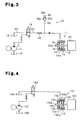
- Fig. 3 is a hydraulic circuit diagram illustrating a parking brake device according to a modified embodiment of the present invention; and
- Fig. 4 is a hydraulic circuit diagram illustrating a prior art parking brake device.
- One embodiment of the present invention will now be described.
- Fig. 1 shows a hydraulic circuit of a
parking brake device 10 used in industrial vehicles such as a forklift. The forklift has adrive motor 20 and abraking portion 11, which is located in the vicinity of thedrive motor 20. Thebraking portion 11 has ahousing 12, which accommodates abrake disk 13 and apiston 14. Thebrake disk 13 rotates integrally with anoutput shaft 20a of thedrive motor 20. Thepiston 14 has abrake pad 14a, which moves relative to thebrake disk 13 in the axial direction. Aspring 15, which urges thepiston 14 in a direction such that thebrake pad 14a approaches thebrake disk 13, and acontrol oil chamber 16, which applies force on thepiston 14 in a direction opposite to the force of thespring 15 based on the internal pressure, are provided in thehousing 12 of thebraking portion 11. - The
control oil chamber 16 of thebraking portion 11 is connected to ahydraulic pump 17 and anoil tank 18 via anelectromagnetic switching valve 19. Theparking brake device 10 shares thehydraulic pump 17 and theoil tank 18 with a service brake device and a power steering device, which are not shown. That is, asupply pipe 21, which extends from thehydraulic pump 17, and adischarge pipe 22, which extends from theoil tank 18 are connected to theswitching valve 19. Theswitching valve 19 is connected to an oil supply/discharge passage 23, which extends from thecontrol oil chamber 16 of thebraking portion 11. In this embodiment, thesupply pipe 21 and the oil supply/discharge passage 23 form a supply passage, and thedischarge pipe 22 and the oil supply/discharge passage 23 form a discharge passage. The discharge passage and the supply passage share the oil supply/discharge passage 23. That is, part of the discharge passage and part of the supply passage forms the common supply/discharge passage 23. Sharing the oil supply/discharge passage 23 simplifies the structure of the hydraulic circuit. - When an electromagnetic actuator is de-excited (the
switching valve 19 is switched OFF), theswitching valve 19 connects the oil supply/discharge passage 23 to thedischarge pipe 22, that is, theswitching valve 19 connects thecontrol oil chamber 16 of thebraking portion 11 to theoil tank 18 without passing thehydraulic pump 17. When an electromagnetic actuator is excited (theswitching valve 19 is switched ON), theswitching valve 19 connects the oil supply/discharge passage 23 to thesupply pipe 21, that is, theswitching valve 19 connects thehydraulic pump 17 to thecontrol oil chamber 16 of thebraking portion 11. - A
piston chamber 25 is defined in the oil supply/discharge passage 23. Thepiston chamber 25 accommodates apiston 26, which defines afirst oil chamber 25a on the side facing thecontrol oil chamber 16 and asecond oil chamber 25b on the side facing theswitching valve 19. Thesecond oil chamber 25b accommodates aspring 27, which urges thepiston 26 toward thefirst oil chamber 25a. Apiston passage 26a is formed in thepiston 26 to connect thefirst oil chamber 25a to thesecond oil chamber 25b. A dischargedoil restrictor 28 is located in thepiston passage 26a. - A supplied
oil bypass passage 31, which bypasses thepiston chamber 25, that,is, bypasses the dischargedoil restrictor 28, is connected to the oil supply/discharge passage 23. A suppliedoil check valve 32, which permits hydraulic oil to flow toward thecontrol oil chamber 16 of thebraking portion 11 from theswitching valve 19, is located in the suppliedoil bypass passage 31. That is, the suppliedoil check valve 32 prevents hydraulic oil from flowing toward theswitching valve 19 from thecontrol oil chamber 16 through the suppliedoil bypass passage 31. - An
accumulator 35 is connected to a section of the oil supply/discharge passage 23 between thecontrol oil chamber 16 and the piston chamber 25 (the discharged oil restrictor 28) via abranch passage 33. Thebranch passage 33 and the section of the oil supply/discharge passage 23 between thecontrol oil chamber 16 and the joint portion with thebranch passage 33 form an accumulator passage. Theaccumulator 35 is spring type. Theaccumulator 35 accommodates apiston 35a. Thepiston 35a divides the inside of theaccumulator 35 into a space, which accommodates aspring 35b, and ahydraulic chamber 35c. Thebranch passage 33 is connected to theaccumulator 35 at thehydraulic chamber 35c. - An
oil accumulation restrictor 37 is located in thebranch passage 33. An oil releasingbypass passage 38 for bypassing theoil accumulation restrictor 37 is connected to thebranch passage 33 at the front and rear of theoil accumulation restrictor 37. An oil releasingcheck valve 39, which permits hydraulic oil to flow toward the oil supply/discharge passage 23 from the accumulator 35 (thehydraulic chamber 35c), is located in the oil releasingbypass passage 38. That is, the oil releasingcheck valve 39 prevents hydraulic oil from flowing toward theaccumulator 35 from the oil supply/discharge passage 23. When the occupant switches the switchingvalve 19 ON, hydraulic oil is supplied to the oil supply/discharge passage 23 from thehydraulic pump 17 via the switching valve 19 (non-braking state of the parking brake device 10). The hydraulic oil supplied to the oil supply/discharge passage 23 is supplied to thecontrol oil chamber 16 of thebraking portion 11 mainly via the suppliedoil bypass passage 31. Therefore, thepiston 14 moves against the force of thespring 15 reducing the contact force between thebrake pad 14a and thebrake disk 13. Accordingly, theparking brake device 10 loses braking force. - When the
parking brake device 10 is in the non-braking state, hydraulic oil is supplied to the accumulator 35 (hydraulic chamber 35c) from thehydraulic pump 17 via the oil supply/discharge passage 23 and the branch passage 33 (the oil accumulation restrictor 37). Therefore, in theaccumulator 35, thepiston 35a moves against the force of thespring 35b to expand thehydraulic chamber 35c. The hydraulic oil is introduced into thehydraulic chamber 35c and accumulated therein. When the hydraulic pressure in thehydraulic chamber 35c achieves the maximum accumulation value, theaccumulator 35 stops expanding thehydraulic chamber 35c and the introduction of hydraulic oil into thehydraulic chamber 35c is stopped. Theaccumulator 35 therefore becomes incapable of accumulating more hydraulic oil. The maximum accumulation value of theaccumulator 35 is set to a value far lower than the maximum pressure of thecontrol oil chamber 16 of thebraking portion 11 during the non-braking state of the parking brake device 10 (the setting will be described later). - When the
parking brake device 10 is in the non-braking state, hydraulic oil is supplied to thesecond oil chamber 25b of thepiston chamber 25 from thehydraulic pump 17. Since thepiston passage 26a, which connects thesecond oil chamber 25b to thefirst oil chamber 25a, is restricted by the dischargedoil restrictor 28, the pressure in thesecond oil chamber 25b becomes greater than the pressure in thefirst oil chamber 25a. The increased pressure in thesecond oil chamber 25b and the force of thespring 27, which urges thepiston 26 toward thefirst oil chamber 25a, cause thepiston 26 to move toward thefirst oil chamber 25a, thereby minimizing the volume of thefirst oil chamber 25a. - When the occupant switches the switching
valve 19 OFF, the oil supply/discharge passage 23 is connected to theoil tank 18 via the switchingvalve 19 and thedischarge pipe 22 without passing the hydraulic pump 17 (braking state of the parking brake device 10). Therefore, the hydraulic oil in thecontrol oil chamber 16 of thebraking portion 11 is discharged to theoil tank 18 via the switchingvalve 19 and thedischarge pipe 22 while being restricted by the dischargedoil restrictor 28. - Fig. 2 is a graph showing pressure changes over time in the
control oil chamber 16 of thebraking portion 11. The time t0 at which the switchingvalve 19 is switched OFF, that is, the time t0 at which theparking brake device 10 is switched from the non-braking state to the braking state is set to the origin of the graph. As shown in Fig. 2, the pressure P1 in thecontrol oil chamber 16 at the time t1 at which thebraking portion 11 exerts braking force is lower than the pressure P2 in thecontrol oil chamber 16 at the time t0 at which theparking brake device 10 is switched from the non-braking state to the braking state. This is because thebraking portion 11 has a no reaction region of the braking force from when theparking brake device 10 is switched from the non-braking state to the braking state until when thebrake pad 14a contacts thebrake disk 13. - When the
parking brake device 10 is switched from the non-braking state to the braking state, hydraulic oil is supplied to thefirst oil chamber 25a of thepiston chamber 25 from thecontrol oil chamber 16 of thebraking portion 11. Since thepiston passage 26a is restricted by the dischargedoil restrictor 28, the pressure in thefirst oil chamber 25a becomes greater than the pressure in thesecond oil chamber 25b. Therefore, thepiston 26 moves toward thesecond oil chamber 25b against the force of thespring 27 and the force based on the pressure in thesecond oil chamber 25b to increase the volume of thefirst oil chamber 25a from the minimum volume. Therefore, the hydraulic oil in thecontrol oil chamber 16 of thebraking portion 11 is promptly discharged and the pressure in thecontrol oil chamber 16 is quickly decreased. - The maximum volume of the
first oil chamber 25a is slightly less than the maximum volume of thecontrol oil chamber 16 of thebraking portion 11. That is, increasing the volume of thefirst oil chamber 25a promotes discharging of the hydraulic oil from thecontrol oil chamber 16 until immediately before thebrake pad 14a contacts thebrake disk 13, that is, immediately before braking force is exerted. With this structure, exertion of braking force is prevented from being delayed. - At the time t2, which is after the time t1 at which the volume of the
first oil chamber 25a is maximized, the hydraulic oil in thehydraulic chamber 35c of theaccumulator 35 is released to the section of the oil supply/discharge passage 23 between to thecontrol oil chamber 16 and the dischargedoil restrictor 28 via the oil releasing bypass passage 38 (the oil releasing check valve 39). Therefore, hardly any hydraulic oil is discharged from thecontrol oil chamber 16 until the time t3 at which the volume of thehydraulic chamber 35c is minimized and theaccumulator 35 completes releasing the oil. Accordingly, the pressure in thecontrol oil chamber 16 is maintained to be substantially constant. Thus, the contact force between thebrake disk 13 and thebrake pad 14a is maintained constant and the braking force exerted by the brakingportion 11 is maintained to be substantially constant. - That is, in the preferred embodiment, the
accumulator 35 is designed to release oil at a time when the braking force is greater than that at the time t0, at which theparking brake device 10 is switched from the non-braking state to the braking state, and the braking force can further be increased during the braking state of theparking brake device 10. More specifically, the maximum accumulation value P3 of theaccumulator 35 is set to a value less than or equal to the pressure P1 in thecontrol oil chamber 16 at the time t1 at which the braking force starts increasing from when theparking brake device 10 is switched from the non-braking state to the braking state. In other words, the braking force starts to increase when the pressure in thecontrol oil chamber 16 is decreased to a predetermined value (pressure P1) after the parking brake device is switched from the non-braking state to the braking state. The maximum accumulation value P3 of theaccumulator 35 is set to a value less than or equal to the predetermined value (pressure P1). - After the time t3, at which the
accumulator 35 completes releasing oil, discharging of the hydraulic oil from thecontrol oil chamber 16 of thebraking portion 11 is substantially resumed, and the pressure in thecontrol oil chamber 16 is decreased to the pressure in theoil tank 18, that is, the tank pressure P0. After the time t4 at which the pressure in thecontrol oil chamber 16 is equalized with the tank pressure P0, thebrake pad 14a abuts against thebrake disk 13 with the maximum force exerted by the force of thespring 15. Accordingly, the braking force exerted by the brakingportion 11 is maximized. - In other words, when the
parking brake device 10 is switched from the non-braking state to the braking state, the pressure P in thecontrol oil chamber 16 decreases from P2 to the tank pressure P0. The pressure decrease in thecontrol oil chamber 16 increases the braking force to the predetermined upper limit value (the braking force value corresponding to the tank pressure P0), that is, the maximum force exerted by thespring 15. Theaccumulator 35 releases hydraulic oil to thecontrol oil chamber 16 during a process of increasing the braking force to the upper limit value. That is, theaccumulator 35 releases hydraulic oil to thecontrol oil chamber 16 when the braking force is less than the upper limit value. - The preferred embodiment has the following advantages.
- (1) When the
parking brake device 10 is in the braking state, theaccumulator 35 and the dischargedoil restrictor 28 cooperates, until theaccumulator 35 completes releasing oil, to maintain the braking force that is greater than that at the time t0, at which theparking brake device 10 is switched from the non-braking state, and not the maximum. Therefore, for example, when theparking brake device 10 is switched from the non-braking state to the braking state while the vehicle is traveling, the braking force is prevented from abruptly and excessively increasing and the maximum value of the absolute value of deceleration is decreased. Thus, theparking brake device 10 gradually brakes the vehicle from the running state. - (2) The
oil accumulation restrictor 37 is located in thebranch passage 33 connected to theaccumulator 35. Therefore, when theparking brake device 10 is switched from the braking state to the non-braking state, the hydraulic oil supplied from thehydraulic pump 17 to theaccumulator 35 is restricted by theoil accumulation restrictor 37. Thus, the pressure in thecontrol oil chamber 16 is promptly increased thereby preventing theparking brake device 10 from being released with a delay. - (3) The
accumulator 35 and the oil supply/discharge passage 23 are connected to each other by the oil releasingbypass passage 38, which bypasses theoil accumulation restrictor 37. The oil releasingcheck valve 39, which permits hydraulic oil to flow toward the oil supply/discharge passage 23 from theaccumulator 35, is located in the oil releasingbypass passage 38. Therefore, the hydraulic oil in theaccumulator 35 is mainly supplied to thecontrol oil chamber 16 via the oil releasingbypass passage 38, which is opened by the oil releasingcheck valve 39, bypassing theoil accumulation restrictor 37. Thus, releasing of oil by theaccumulator 35 is prevented from being hindered by theoil accumulation restrictor 37. This reliably prevents the braking force from abruptly and excessively increasing. - (4) The supplied
oil bypass passage 31, which bypasses the dischargedoil restrictor 28, is connected to the oil supply/discharge passage 23. The suppliedoil check valve 32, which permits hydraulic oil to flow toward thecontrol oil chamber 16 from the switchingvalve 19, is located in the suppliedoil bypass passage 31. Therefore, when theparking brake device 10 is switched from the braking state to the non-braking state, the hydraulic oil in thehydraulic pump 17 is mainly supplied to thecontrol oil chamber 16 via the suppliedoil bypass passage 31, which is opened by the suppliedoil check valve 32, bypassing the dischargedoil restrictor 28. Thus, the pressure in thecontrol oil chamber 16 is promptly increased and the braking force is quickly decreased. This prevents theparking brake device 10 from being released with a delay. - The invention may be embodied in the following forms.
- As shown in Fig. 3, in the above embodiment, the
piston chamber 25 and the structure (such as the piston 26) in thepiston chamber 25 may be eliminated and the dischargedoil restrictor 28 may be directly located in the oil supply/discharge passage 23. The suppliedoil bypass passage 31, the suppliedoil check valve 32, theoil accumulation restrictor 37, the oil releasingbypass passage 38, and the oil releasingcheck valve 39 may be eliminated. - In the above embodiment, the
accumulator 35 is spring type. However, theaccumulator 35 may be bladder type, diaphragm type, rubber tube type, or piston type. - In the above embodiment, the present invention is embodied in the
parking brake device 10 used in an industrial vehicle, which is a forklift. However, theparking brake device 10 may be applied to industrial vehicles other than forklifts such as a bucket loader. - The present examples and embodiments are to be considered as illustrative and not restrictive and the invention is not to be limited to the details given herein, but may be modified within the scope of the appended claims.
Claims (8)
- A hydraulic parking brake device of a vehicle, wherein the device is selectively switched between a braking state and a non-braking state, the device comprising:a braking portion (11), which generates a braking force, the braking portion (11) having a control oil chamber (16) into which hydraulic oil flows, the braking force decreases as the pressure in the control oil chamber (16) increases and increases as the pressure in the control oil chamber (16) decreases;an oil tank (18);a hydraulic pump (17);a supply passage (21, 23), which connects the hydraulic pump (17) to the control oil chamber (16) in the non-braking state; anda discharge passage (22, 23), which connects the control oil chamber (16) to the oil tank (18) in the braking state;the parking brake device being characterized by:a discharged oil restrictor (28) located in the discharge passage (22, 23); andan accumulator (35) connected to the control oil chamber (16), wherein the accumulator (35) is capable of releasing hydraulic oil to the control oil chamber (16) when the braking force is greater than that at the time when the parking brake device is switched from the non-braking state to the braking state and the braking force can further be increased during the braking state of the parking brake device.
- The parking brake device according to claim 1, characterized by an urging member, which generates an urging force to increase the braking force, wherein force based on the pressure of the control oil chamber (16) is applied in a direction opposite to the urging force of the urging member.
- The parking brake device according to claim 1, characterized in that the maximum accumulation value of the accumulator (35) is set to a value less than or equal to a pressure in the control oil chamber (16) at the time at which the braking force starts increasing from when the parking brake device is switched from the non-braking state to the braking state.
- The parking brake device according to any one of claims 1 to 3, characterized by:an accumulator passage (23, 33), which connects the accumulator (35) to the control oil chamber (16); andan oil accumulation restrictor (37) located in the accumulator passage (23, 33).
- The parking brake device according to claim 4, characterized by:an oil releasing bypass passage (38), which connects the accumulator (35) to the control oil chamber (16) bypassing the oil accumulation restrictor (37); andan oil releasing check valve (39) located in the oil releasing bypass passage (38), wherein the oil releasing check valve (39) permits flow of hydraulic oil from the accumulator (35) to the control oil chamber (16).
- The parking brake device according to any one of claims 1 to 5, characterized by a switching valve (19), which selects the braking state and the non-braking state of the parking brake device, wherein the switching valve (19) is connected the oil tank (18) and the hydraulic pump (17), respectively,
wherein part of the discharge passage and part of the supply passage forms a common supply/discharge passage (23), the discharged oil restrictor (28) is located in the supply/discharge passage (23), the switching valve (19) is connected to the control oil chamber (16) via the common supply/discharge passage (23). - The parking brake device according to claim 6, characterized by:a supplied oil bypass passage (31), which is connected to the supply/discharge passage (23) bypassing the discharged oil restrictor (28); anda supplied oil check valve (32) located in the supplied oil bypass passage (31), wherein the supplied oil check valve (32) permits flow of hydraulic oil from the switching valve (19) to the control oil chamber (16).
- The parking brake device according to any one of claims 1 to 7, characterized by:a piston chamber (25) defined in the discharge passage;a piston (26) accommodated in the piston chamber (25), the piston (26) divides the piston chamber (25) into a first oil chamber (25a) facing the control oil chamber (16) and a second oil chamber (25b) facing the oil tank (18); anda piston passage (26a) located in the piston (26), the piston passage (26a) connects the first oil chamber (25a) to the second oil chamber (25b), and the discharged oil restrictor (28) is located in the piston passage (26a).
Applications Claiming Priority (2)
| Application Number | Priority Date | Filing Date | Title |
|---|---|---|---|
| JP2003413451A JP4164020B2 (en) | 2003-12-11 | 2003-12-11 | Vehicle parking brake device |
| JP2003413451 | 2003-12-11 |
Publications (3)
| Publication Number | Publication Date |
|---|---|
| EP1541438A2 EP1541438A2 (en) | 2005-06-15 |
| EP1541438A3 EP1541438A3 (en) | 2005-12-21 |
| EP1541438B1 true EP1541438B1 (en) | 2007-02-21 |
Family
ID=34510544
Family Applications (1)
| Application Number | Title | Priority Date | Filing Date |
|---|---|---|---|
| EP04029158A Expired - Lifetime EP1541438B1 (en) | 2003-12-11 | 2004-12-09 | Parking brake device of vehicle |
Country Status (4)
| Country | Link |
|---|---|
| US (1) | US7273136B2 (en) |
| EP (1) | EP1541438B1 (en) |
| JP (1) | JP4164020B2 (en) |
| DE (1) | DE602004004860T2 (en) |
Cited By (1)
| Publication number | Priority date | Publication date | Assignee | Title |
|---|---|---|---|---|
| EP3421311B1 (en) * | 2017-06-27 | 2022-03-30 | Poclain Hydraulics Industrie | Emergency brake device with variable torque |
Families Citing this family (16)
| Publication number | Priority date | Publication date | Assignee | Title |
|---|---|---|---|---|
| US7374252B2 (en) * | 2006-03-16 | 2008-05-20 | Wabtec Holding Corporation | Wheel slip brake assurance module |
| ITBO20060714A1 (en) * | 2006-10-16 | 2008-04-17 | Cnh Italia Spa | PARKING BRAKE, IN PARTICULAR FOR AN AGRICULTURAL TRACTOR, EQUIPPED WITH A SAFETY DEVICE |
| JP4732396B2 (en) * | 2007-03-30 | 2011-07-27 | 日信工業株式会社 | Brake device for vehicle |
| US8186772B2 (en) | 2007-03-30 | 2012-05-29 | Nissin Kogyo Co., Ltd. | Vehicle brake apparatus |
| DE102009031741B4 (en) | 2008-07-29 | 2022-01-05 | Linde Material Handling Gmbh | Mobile working machine with spring-loaded brake |
| US9067576B2 (en) * | 2011-09-16 | 2015-06-30 | International Truck Intellectual Property Company, Llc | Hydraulic powered park brake system |
| CN103661337A (en) * | 2012-09-05 | 2014-03-26 | 卡特彼勒公司 | Method and system for releasing break-down machine parking brake and machine comprising system |
| US9061668B2 (en) * | 2013-02-14 | 2015-06-23 | Caterpillar Inc. | Brake system |
| DE102013108495B4 (en) * | 2013-08-07 | 2017-08-24 | Mhwirth Gmbh | Lift brake system |
| DE102014202165B4 (en) * | 2014-02-06 | 2026-01-22 | Robert Bosch Gmbh | Method for providing a clamping force generated by an automatic parking brake to a vehicle |
| CN104943670B (en) * | 2014-04-30 | 2017-10-31 | 比亚迪股份有限公司 | Fork truck, brakes and its braking method for fork truck |
| EP3524962A1 (en) * | 2015-12-09 | 2019-08-14 | Diamontech GmbH | Device and method for analysing a material |
| US10408347B2 (en) * | 2017-10-20 | 2019-09-10 | Ford Global Technologies, Llc | Transmission park control system |
| JP2020183137A (en) * | 2019-04-27 | 2020-11-12 | 日本ケーブル株式会社 | Hydraulic unit for brakes of rope tow type transportation equipment |
| CN114017450B (en) * | 2021-10-29 | 2023-09-12 | 中国第一汽车股份有限公司 | Hydraulic control device of automatic transmission |
| US20240336354A1 (en) * | 2023-04-10 | 2024-10-10 | Goodrich Corporation | Electric-hydraulic brake actuators for braking and parking |
Family Cites Families (15)
| Publication number | Priority date | Publication date | Assignee | Title |
|---|---|---|---|---|
| GB1217747A (en) * | 1968-04-08 | 1970-12-31 | North American Rockwell | Brake system |
| DE2008052A1 (en) * | 1970-02-21 | 1971-09-02 | ||
| US3802746A (en) * | 1972-08-23 | 1974-04-09 | Clark Equipment Co | Articulated tractor vehicle power steering and brake system having an emergency brake device |
| JPS51123480A (en) | 1975-04-08 | 1976-10-28 | Siemens Ag | Brake device for transfer machine |
| JPS59145445A (en) | 1983-02-08 | 1984-08-20 | Daikin Ind Ltd | Storage type hot water feed device |
| JPS613164A (en) | 1984-06-16 | 1986-01-09 | Ricoh Co Ltd | image editing copier |
| JPS62194172A (en) | 1986-02-19 | 1987-08-26 | ダイキン工業株式会社 | Controller for refrigerator |
| JPS63111361A (en) | 1986-10-24 | 1988-05-16 | Chugoku Kiko:Kk | Water cooling type mechatro-slide unit |
| JP2808937B2 (en) | 1991-08-07 | 1998-10-08 | 神鋼電機株式会社 | Electromagnetic clutch and electromagnetic brake torque control device |
| ES2129480T3 (en) * | 1993-10-18 | 1999-06-16 | Inventio Ag | BRAKING SAFETY DEVICE FOR ELEVATOR CABINS. |
| US5601160A (en) * | 1994-10-20 | 1997-02-11 | Case Corporation | Hydraulically actuated brake assembly for an off-highway implement |
| GB2303676B (en) * | 1995-07-22 | 1999-03-10 | Twiflex Ltd | Fluid control circuit and brake system |
| US6105738A (en) * | 1998-02-12 | 2000-08-22 | Inventio Ag | Elevator brake |
| SE516430C2 (en) * | 2000-05-05 | 2002-01-15 | Volvo Articulated Haulers Ab | Device and method for activating an emergency brake function of a vehicle |
| ES2345880T3 (en) * | 2002-03-23 | 2010-10-05 | General Electric Company | HYDRAULIC BRAKE SYSTEM FOR A WIND ENERGY INSTALLATION. |
-
2003
- 2003-12-11 JP JP2003413451A patent/JP4164020B2/en not_active Expired - Lifetime
-
2004
- 2004-12-09 DE DE602004004860T patent/DE602004004860T2/en not_active Expired - Lifetime
- 2004-12-09 EP EP04029158A patent/EP1541438B1/en not_active Expired - Lifetime
- 2004-12-10 US US11/009,332 patent/US7273136B2/en not_active Expired - Lifetime
Cited By (1)
| Publication number | Priority date | Publication date | Assignee | Title |
|---|---|---|---|---|
| EP3421311B1 (en) * | 2017-06-27 | 2022-03-30 | Poclain Hydraulics Industrie | Emergency brake device with variable torque |
Also Published As
| Publication number | Publication date |
|---|---|
| JP2005170244A (en) | 2005-06-30 |
| EP1541438A3 (en) | 2005-12-21 |
| DE602004004860T2 (en) | 2007-10-31 |
| EP1541438A2 (en) | 2005-06-15 |
| DE602004004860D1 (en) | 2007-04-05 |
| US20050127748A1 (en) | 2005-06-16 |
| US7273136B2 (en) | 2007-09-25 |
| JP4164020B2 (en) | 2008-10-08 |
Similar Documents
| Publication | Publication Date | Title |
|---|---|---|
| US7273136B2 (en) | Parking brake device of vehicle | |
| US12291184B2 (en) | Brake system | |
| EP0784002B1 (en) | Brake control apparatus for a vehicle | |
| JP5484573B2 (en) | Hydraulic accumulator device and method of operating hydraulic accumulator device | |
| US20080010985A1 (en) | Brake system, stroke simulator disconnecting mechanism, and stroke simulator disconnecting method | |
| US8915080B2 (en) | Pressure generator of a hydraulic vehicle brake system and operating method for this | |
| US20040183373A1 (en) | Brake pressure control device in brake system | |
| US5947566A (en) | Brake booster system | |
| JPH04300765A (en) | Two circuit brake gear | |
| KR100297932B1 (en) | Vehicle brake device | |
| US6003957A (en) | Fluid pressure control apparatus for wheel brakes | |
| JP2016537240A (en) | Brake pressure booster control method and brake pressure booster device with hydraulic brake boosting | |
| JP3932153B2 (en) | Brake system | |
| KR102487781B1 (en) | Regenerative braking system for a vehicle and method for operating the regenerative braking system in a vehicle | |
| JPH0423719Y2 (en) | ||
| US8260514B2 (en) | Method for supporting a brake system in case of reduced effectiveness | |
| JP3959578B2 (en) | Hydraulic pressure source circuit in hydraulic booster | |
| JPH08104217A (en) | Brake system | |
| JPH11227587A (en) | Brake equipment | |
| JPS60209351A (en) | Antiskid device | |
| JPH10264790A (en) | Braking force control device | |
| JPH07223527A (en) | Vehicle traction control device | |
| JPH1170872A (en) | Hydraulic boosting device | |
| JPH0678135U (en) | Hydraulic control device for anti-skid device | |
| JPH11115705A (en) | Brake fluid pressure control device |
Legal Events
| Date | Code | Title | Description |
|---|---|---|---|
| PUAI | Public reference made under article 153(3) epc to a published international application that has entered the european phase |
Free format text: ORIGINAL CODE: 0009012 |
|
| 17P | Request for examination filed |
Effective date: 20041209 |
|
| AK | Designated contracting states |
Kind code of ref document: A2 Designated state(s): AT BE BG CH CY CZ DE DK EE ES FI FR GB GR HU IE IS IT LI LT LU MC NL PL PT RO SE SI SK TR |
|
| AX | Request for extension of the european patent |
Extension state: AL BA HR LV MK YU |
|
| PUAL | Search report despatched |
Free format text: ORIGINAL CODE: 0009013 |
|
| AK | Designated contracting states |
Kind code of ref document: A3 Designated state(s): AT BE BG CH CY CZ DE DK EE ES FI FR GB GR HU IE IS IT LI LT LU MC NL PL PT RO SE SI SK TR |
|
| AX | Request for extension of the european patent |
Extension state: AL BA HR LV MK YU |
|
| GRAP | Despatch of communication of intention to grant a patent |
Free format text: ORIGINAL CODE: EPIDOSNIGR1 |
|
| AKX | Designation fees paid |
Designated state(s): DE FR GB |
|
| GRAS | Grant fee paid |
Free format text: ORIGINAL CODE: EPIDOSNIGR3 |
|
| GRAA | (expected) grant |
Free format text: ORIGINAL CODE: 0009210 |
|
| AK | Designated contracting states |
Kind code of ref document: B1 Designated state(s): DE FR GB |
|
| REG | Reference to a national code |
Ref country code: GB Ref legal event code: FG4D |
|
| REF | Corresponds to: |
Ref document number: 602004004860 Country of ref document: DE Date of ref document: 20070405 Kind code of ref document: P |
|
| ET | Fr: translation filed | ||
| PLBE | No opposition filed within time limit |
Free format text: ORIGINAL CODE: 0009261 |
|
| STAA | Information on the status of an ep patent application or granted ep patent |
Free format text: STATUS: NO OPPOSITION FILED WITHIN TIME LIMIT |
|
| 26N | No opposition filed |
Effective date: 20071122 |
|
| REG | Reference to a national code |
Ref country code: FR Ref legal event code: PLFP Year of fee payment: 12 |
|
| REG | Reference to a national code |
Ref country code: FR Ref legal event code: PLFP Year of fee payment: 13 |
|
| REG | Reference to a national code |
Ref country code: FR Ref legal event code: PLFP Year of fee payment: 14 |
|
| P01 | Opt-out of the competence of the unified patent court (upc) registered |
Effective date: 20230519 |
|
| PGFP | Annual fee paid to national office [announced via postgrant information from national office to epo] |
Ref country code: GB Payment date: 20231102 Year of fee payment: 20 |
|
| PGFP | Annual fee paid to national office [announced via postgrant information from national office to epo] |
Ref country code: FR Payment date: 20231108 Year of fee payment: 20 Ref country code: DE Payment date: 20231031 Year of fee payment: 20 |
|
| REG | Reference to a national code |
Ref country code: DE Ref legal event code: R071 Ref document number: 602004004860 Country of ref document: DE |
|
| REG | Reference to a national code |
Ref country code: GB Ref legal event code: PE20 Expiry date: 20241208 |
|
| PG25 | Lapsed in a contracting state [announced via postgrant information from national office to epo] |
Ref country code: GB Free format text: LAPSE BECAUSE OF EXPIRATION OF PROTECTION Effective date: 20241208 |
|
| PG25 | Lapsed in a contracting state [announced via postgrant information from national office to epo] |
Ref country code: GB Free format text: LAPSE BECAUSE OF EXPIRATION OF PROTECTION Effective date: 20241208 |