BACKGROUND OF THE INVENTION
Field of the Invention
The invention relates to a hydraulic transaxle, which incorporates a
hydraulic motor for driving a single wheel, and is steerably supported by a
vehicle chassis. The invention also relates to a four-wheel driving vehicle
including the hydraulic transaxles for driving respective wheels.
Related Art
As disclosed in US Patent Application Publication No.
2003/0106725A1, there is a conventional vehicle having left and right
steerable wheels linked to a steering operation device such as a steering wheel.
In the conventional vehicle, according to steering, e.g., according to increase
of a rotational angle of a steering wheel from its straight traveling position,
turning angles of the left and right steerable wheels are increased so that the
turning angle of the steerable wheel on the turning inside of the vehicle
(hereinafter referred to as "inside wheel") becomes larger than that of the
steerable wheel on the turning outside of the vehicle (hereinafter referred to as
"outside wheel").
This vehicle can turn on a small circle by a reduced steering degree (a
small rotational angle of the steering wheel). However, the steerable wheels
are not drivingly connected to a prime mover. The rotary speeds of the
steerable wheels depend upon the speed control of (unsteerable) drive wheels
by an operator's manipulation. Such a vehicle is disadvantageous in traveling
capacity on a bad road and climbing capacity.
As disclosed in Japanese Utility Model Application Publication No.
Sho 58-58932 and Japanese Utility Model Publication No. Sho 62-37775,
there is a conventional four-wheel driving vehicle having four fixed
displacement hydraulic motors for driving respective four wheels, i.e., left and
right front wheels and left and right rear wheels. The left and right front
wheels are steerable wheels, which are steered by turning of a steering wheel.
The hydraulic motors are mounted on a vehicle chassis and drivingly
connected to the respective wheels through respective deceleration gear trains
in respective housings.
The vehicle has left and right variable displacement hydraulic pumps.
The left front and rear hydraulic motors are fluidly connected in parallel to the
left hydraulic pump, and the right front and rear hydraulic motors to the right
hydraulic pump. The front hydraulic motors can be fluidly separated from the
respective hydraulic pumps so as to put the vehicle into a two-wheel drive
mode. By operating a speed control manipulator, the left and right hydraulic
pumps are synchronously controlled in their delivery direction and amount so
as to control the traveling direction and speed of the vehicle. The hydraulic
pumps are fluidly connected to each other so as to allow differential rotation
of left and right rear wheels (and left and right front wheels). The vehicle is
also provided with a valve for differential locking, i.e., cutting off the fluidal
connection between the hydraulic pumps, so as to facilitate escape of the
vehicle from mud or a ditch.
This conventional vehicle is disadvantageous in minimization because
the hydraulic motors and the respective deceleration gear train housings are
mounted upright on the vehicle chassis. The vehicle is also disadvantageous
in cost because of the two hydraulic pump. Further, when the vehicle travels
in the four-wheel drive mode, the front and rear hydraulic motors on each of
left and right sides of the vehicle are fluidly connected in parallel to the
common left or right hydraulic pump, so that the amount of hydraulic fluid
supplied to each of the hydraulic motors is restricted. Therefore, the vehicle is
disadvantageous in efficiency of acceleration, i.e., high-speed traveling.
As disclosed in , there is another conventional vehicle having a
transaxle housing incorporating left and right hydraulic motors for driving
respective left and right wheels. The left and right wheels are supported by
respective left and right wheel support units steerably supported on left and
right ends of the transaxle housing, and drivingly connected to the respective
hydraulic motors. The left and right hydraulic motors are fluidly connected in
parallel to a common hydraulic pump so as to differentially drive the left and
right wheels. The left and right hydraulic motors may be variable in
displacement. In this case, means for controlling the displacements of the
hydraulic motors, e.g., movable swash plates, are operated according to
steering.
The transaxle housing incorporating the left and right hydraulic motors
is laterally extended in the vehicle between the left and right wheel support
units so as to restrict a space for other parts or assemblies in the vehicle.
Further, the large transaxle including the transaxle housing and the left and
right wheel support units is not handy, and is disadvantageous in ensuring a
free space in a small size vehicle.
SUMMARY OF THE INVENTION
A first object of the present invention is to provide a compact and
convenient hydraulic transaxle incorporating a hydraulic motor for driving a
steerable wheel.
To achieve the object, according to a first aspect of the present
invention, a steerable hydraulic transaxle comprises: a kingpin relatively
rotatably supported by a vehicle chassis; a housing fixed to the kingpin; a
single axle disposed in the housing; a single wheel fixed onto the single axle
out of the housing; and a hydraulic motor disposed in the housing so as to
drive the single axle. As a result, the housing supporting the single wheel is
supported by the vehicle chassis so as to be rotatable around the center axis of
the kingpin. Such a compact transaxle is advantageous in ensure a free space
in a small size vehicle.
Preferably, the single axle is coaxially disposed in the hydraulic motor,
thereby facilitating minimization of the steerable hydraulic transaxle.
Preferably, the steerable hydraulic transaxle further comprises motor
control means for changing a displacement of the hydraulic motor in
association with the rotation of the kingpin and the housing relative to the
vehicle chassis. If a turning radius of front wheels is different from a turning
radius of rear wheels during turning of a vehicle, the motor control means of
the transaxle for either the front or rear wheel can change the displacement of
the hydraulic motor so as to accelerate or decelerate the corresponding wheel,
thereby preventing drag of wheels during turning of the vehicle. Even if the
turning radius of front wheels is equal to that of rear wheels, the motor control
means may be used for decelerating the vehicle during its turning.
Further preferably, the steerable hydraulic transaxle having the motor
control means further comprises a kingpin casing fixed to the vehicle chassis.
The kingpin relatively rotatably penetrates the kingpin casing. The motor
control means changes the displacement of the hydraulic motor according to
the rotation of the kingpin relative to the kingpin casing. Further preferably,
the motor control means includes a cam formed on the kingpin casing.
Therefore, the motor control means can be compactly and suitably provided to
the steerable hydraulic transaxle.
Preferably, the kingpin is penetrated so as to pass fluid supplied to the
hydraulic motor in the housing. The kingpin may be a solid shaft bored by a
fluid hole, or a hollow shaft through which fluid pipes may be passed.
Therefore, fluid supplied to the hydraulic motor is protected by the kingpin
without hindering steering of the wheel.
According to a second aspect of the invention, a steerable hydraulic
transaxle comprises: a motor housing fixed to a vehicle chassis, wherein the
motor housing is partly formed as a kingpin; a hydraulic motor disposed in the
motor housing; an axle housing supported by the kingpin to be rotatable
relative to the motor housing; a single axle disposed in the axle housing and
drivingly connected to the hydraulic motor; and a single wheel fixed onto the
single axle out of the axle housing. Therefore, the axle can be spaced from the
hydraulic motor so as to increase the layout variation of the transaxle, e.g., to
increase the height difference between the hydraulic motor and the axle so as
to ensure a large ground clearance of a vehicle.
Preferably, the steerable hydraulic transaxle further comprises: an
output shaft of the hydraulic motor disposed on the center axis of the kingpin;
and a gear train disposed in the axle housing so as to drivingly connect the
output shaft of the hydraulic motor to the single axle. The output shaft
disposed on the center axis of the kingpin can smoothly transmit the output
force of the hydraulic motor to the axle through the gear train while the output
shaft is not interfered with rotation of the axle housing relative to the motor
housing.
Preferably, the steerable hydraulic transaxle further comprises motor
control means for changing a displacement of the hydraulic motor in
association with the rotation of the axle housing relative to the motor housing.
Therefore, the displacement of the hydraulic motor can be changed to prevent
dragging of running wheels even if a turning radius of front wheels is different
from that of rear wheels. The motor control means may be used for increasing
the displacement of the hydraulic motor so as to safely decelerate a vehicle
while the vehicle turns. Further, the motor control means may be used for
reducing the displacement of the hydraulic motor so as to increase a high-speed
traveling efficiency of a vehicle.
A second object of the invention is to provide a vehicle having
hydraulic motors for respective front and rear wheels, wherein the vehicle can
change its traveling speed level so as to ensure optimal traveling efficiency.
To achieve the second object, according to a third aspect of the
invention, a vehicle comprises: a pair of steerable left and right first wheels
disposed at one of front and rear portions of the vehicle; a first hydraulic
motor for driving the pair of first wheels; a pair of left and right second wheels
disposed at the other rear or front portion of the vehicle; a second hydraulic
motor for driving the pair of second wheels; a common hydraulic pump fluidly
connected to the first and second hydraulic motor; and a switching valve
interposed between the common hydraulic pump and the first and second
hydraulic motors. The switching valve can be switched between a parallel
connection position and a tandem connection position. The switching valve
disposed at the parallel connection position fluidly connects the first and
second hydraulic motors in parallel to the hydraulic pump. The switching
valve disposed at the tandem connection position fluidly connects the first and
second hydraulic motors in tandem to the hydraulic pump. Due to the tandem
connection of the first and second hydraulic motors to the hydraulic pump, the
vehicle can efficiently travel at high speed in the four-wheel drive mode.
Preferably, the vehicle further comprises motor control means for
changing a displacement of the first hydraulic motor according to a steering
operation of the pair of first wheels. The motor control means may be used for
safely decelerating the turning vehicle. Alternatively or additionally, the
motor control means may be used for changing the speed of either the front
wheels or the rear wheels so as to correspond to a difference of turning radius
between the front wheels and the rear wheels during turning of the vehicle,
thereby preventing dragging of wheels.
Preferably, the vehicle further comprises motor control means for
changing a displacement of the second hydraulic motor. The switching valve
can be further switched to a two-wheel driving mode position. The switching
valve disposed at the two-wheel driving mode position fluidly connects not the
first hydraulic motor but the second hydraulic motor to the hydraulic pump.
The motor control means reduces the displacement of the second hydraulic
motor when the switching valve is disposed at the two-wheel driving mode
position. Therefore, the high-speed traveling efficiency of the vehicle set in
the two-wheel driving mode is enhanced.
Preferably, a pair of the first hydraulic motors for driving the
respective left and right first wheels are fluidly connected in parallel to the
hydraulic pump whether the switching valve is disposed at the parallel
connection position or at the tandem connection position. Therefore, the left
and right first wheels can be differentially rotated so as to smoothly turn the
vehicle.
Further preferably, the vehicle having the pair of first hydraulic motors
further comprises a pair of first transaxles incorporating the respective first
hydraulic motors and supporting the respective first wheels. The pair of first
transaxles are steerably supported by the vehicle chassis so that the pair of first
wheels supported by the respective first transaxles serve as steerable wheels.
The pair of first transaxles can be compactly disposed on the vehicle so as to
facilitate minimization of the vehicle, and they can ensure a large free space
therebetween in the vehicle.
Alternatively, further preferably, the vehicle having the pair of first
hydraulic motors further comprises motor control means for changing
displacement of the first hydraulic motors according to a steering operation of
the pair of first wheels. The above-mentioned effect of the motor control
means can be obtained while the differential rotation of the left and right first
wheels is ensured.
Preferably, the vehicle having the pair of first hydraulic motors is
provided with a pair of the second hydraulic motors for driving the respective
second wheels are fluidly connected in parallel to the hydraulic pump whether
the switching valve is disposed at the parallel connection position or at the
tandem connection position. Therefore, the left and right second wheels can
be differentially rotated so as to smoothly turn the vehicle.
Further preferably, the pair of second wheels driven by the respective
second hydraulic motors are steerable. Therefore, the turning circle of the
vehicle can be further reduced.
Further preferably, the vehicle having the steerable first and second
wheels further comprises motor control means for changing displacement of
the first and second hydraulic motors according to a steering operation of the
first and second wheels. The motor control means may be used for safely
decelerating the turning vehicle. Alternatively or additionally, the motor
control means may be used for the speed of either the front wheels or the rear
wheels so as to correspond to a difference of turning radius between the front
wheels and the rear wheels during turning of the vehicle, thereby preventing
dragging of wheels. Further, the motor control means may be used for
increase the high-speed traveling efficiency of the vehicle. These effects of
the motor control means can be obtained while the differential rotation of the
left and right first wheels and the differential rotation of the left and right
second wheels are ensured.
Preferably, the vehicle having the pair of second hydraulic motors
further comprises a pair of second transaxles incorporating the respective
second hydraulic motors and supporting the respective second wheels. The
pair of second transaxles can be compactly disposed on the vehicle so as to
facilitate minimization of the vehicle, and they can ensure a large free space
therebetween in the vehicle.
Further preferably, the pair of second transaxles are steerably
supported by the vehicle chassis so that the pair of second wheels supported
by the respective second transaxles serve as steerable wheels. The vehicle can
turn on a finely small circle by the steerable first and second wheels.
These, other and further objects, features and advantages will appear
more fully from the following description with reference to accompanying
drawings.
BRIEF DESCRIPTION OF THE DRAWINGS
Fig. 1 is a schematic plan view of a four-wheel driving and two-wheel
steering vehicle 1 having left and right steerable front transaxles 15 (15L and
15R) with respective front wheels 36 and left and right unsteerable rear
transaxles 13 (13L and 13R) with respective rear wheels 79 when vehicle 1 is
directed straight.
Fig. 2 is a diagram of a steering linkage 18 of vehicle 1 of Fig. 1 when
vehicle 1 is directed straight.
Fig. 3 is a sectional rear view of front transaxle 15 (left front transaxle
15L).
Fig. 4 is a diagram of steering linkage 18 of vehicle 1 of Fig. 1 when
vehicle 1 turns left.
Fig. 5 is a schematic plan view of vehicle 1 shown in Fig. 1 when
vehicle 1 turns left while left rear wheel 79 is stationary.
Fig. 6 is a sectional rear view of an upper portion of front transaxle 15
shown in Fig. 3, showing a kingpin support casing 26 and kingpin sleeve 27
therethrough.
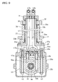
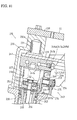
Fig. 7 is a sectional rear view of a lower portion of front transaxle 15
shown in Fig. 3, showing a steerable transaxle housing 28 incorporating a
hydraulic motor 10, a deceleration gear train 38 and an axle 35.
Fig. 8 is a cross sectional view of transaxle 15 taken along a VIII-VIII
line of Fig. 3, showing transaxle housing 28 incorporating hydraulic
motor 10 and axle 35.
Fig. 9 is a cross sectional view of transaxle 15 taken along a IX - IX
line of Fig. 3, showing the upper portion thereof including kingpin support
casing 26 and kingpin sleeve 27, and the lower portion thereof including
steerable transaxle housing 28 and a center section 41 of hydraulic motor 10.
Fig. 10 is a cross sectional view of transaxle 15 taken along a X - X
line of Fig. 3, showing a shape of a cam 26a formed on kingpin support casing
26.
Fig. 11 is a plan view of a clamping portion 71a of a motor control arm
71 to be fitted onto cam 26a.
Fig. 12 is a plan view of steerable transaxle housing 28 of front
transaxle 15 incorporating hydraulic motor 10.
Fig. 13(a) is an axially sectional view of clamping portion 71a of
motor control arm 71 clamping cam 26a when a steering wheel 16 is disposed
at a straight traveling position.
Fig. 13(b) is an axially sectional view of clamping portion 71a of
motor control arm 71 clamping cam 26a when steering wheel 16 is rotated so
as to direct corresponding wheel 36 on the turning inside of vehicle 1.
Fig. 13(c) is an axially sectional view of clamping portion 71a of
motor control arm 71 clamping cam 26a when steering wheel 16 is rotated so
as to direct corresponding wheel 36 on the turning outside of vehicle 1.
Fig. 14 is a sectional rear view of rear transaxle 13 (left rear transaxle
13L), showing a transaxle housing 76 incorporating a hydraulic motor 80 for
driving rear wheel 79.
Fig. 15 is a diagram of a hydraulic circuit system of vehicle 1 shown in
Fig. 1, comprising a first hydraulic circuit 89 for the pair of hydraulic motors
10, a second hydraulic circuit 90 for the pair of hydraulic motors 80, and an
auxiliary speed changing system including an auxiliary speed changing valve
92.
Fig. 16 is a diagram of an alternative first hydraulic circuit 89.
Fig. 17 is a diagram of an electric control system of vehicle 1 shown in
Fig. 1 for controlling step motors 98a and 99a of flow control valves 98 and 99
shown in Fig. 15.
Fig. 18 is a schematic plan view of an alternative four-wheel driving
vehicle 1 having left and right steerable front transaxles 15 (15L and 15R) and
a rear transaxle 114 unsteerably supporting left and right rear wheels 119,
wherein a transaxle housing 117 of rear transaxle 114 incorporates hydraulic
pump 5 and a hydraulic motor 115 for driving rear wheels 119.
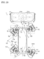
Fig. 19 is a schematic plan view of an alternative four-wheel driving
vehicle 1 having left and right steerable front transaxles 15 (15L and 15R) and
rear transaxle 114 steerably supporting left and right rear wheels 119, wherein
transaxle housing 117 of rear transaxle 114 incorporates hydraulic pump 5 and
hydraulic motor 115 for driving rear wheels 119.
Fig. 20 is a schematic plan view of an alternative four-wheel driving
vehicle 1 having left and right steerable front transaxles 15 (15L and 15R) and
rear transaxle 114 unsteerably supporting left and right rear wheels 119,
wherein hydraulic pump 5 is disposed out of transaxle housing 117 of rear
transaxle 114 incorporating hydraulic motor 115 for driving rear wheels 119.
Fig. 21 is a diagram of a hydraulic circuit system used for vehicles 1
shown in Figs. 18 to 20, comprising first hydraulic circuit 89 for front
transaxles 15, a second hydraulic circuit 120 for rear transaxle 114 and the
auxiliary speed changing system including auxiliary speed changing valve 92.
Fig. 22 is a sectional rear view of an alternative vertically shortened
front transaxle 15 (left front transaxle 15L).
Fig. 23 is a sectional rear view of a lower portion of an alternative
front transaxle 15, showing an alternative housing 124 incorporating hydraulic
motor 10 and an alternative axially shortened deceleration gear train 38.
Fig. 24 is a cross sectional view taken along a XXIV - XXIV line of
Fig. 23.
Fig. 25 is a plan view of transaxle housing 124 of transaxle 15 shown
in Fig. 23.
Fig. 26 is a schematic plan view of an alternative four-wheel driving
and steering vehicle 1 having left and right steerable front transaxles 15 (15L
and 15R) with respective front wheels 36 and left and right steerable rear
transaxles 157 (157L and 157R) with respective rear wheels 167 when vehicle
1 is directed straight.
Fig. 27 is a diagram of an alternative steering linkage 18 of vehicle 1
of Fig. 26 including left and right front steering gear trains 17 and left and
right rear steering gear trains 155, when vehicle 1 is directed straight.
Fig. 28 is a sectional rear view of rear transaxle 157 (left rear transaxle
157L), showing a housing 166 incorporating a hydraulic motor 165 for driving
rear wheel 167.
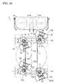
Fig. 29 is a schematic plan view of vehicle 1 shown in Fig. 26 when
vehicle 1 turns left.
Fig. 30 is a schematic plan view of vehicle 1 shown in Fig. 26 when
vehicle 1 spins.
Fig. 31 is an axially sectional view of an alternative kingpin support
casing 170 and kingpin sleeve 27 of front transaxle 15 in vehicle 1 shown in
Fig. 26, wherein a cam 170a is formed on kingpin support casing 170.
Fig. 32 is an axially sectional view of a kingpin support casing 162 and
kingpin sleeve 27 of rear transaxle 157 in vehicle 1 shown in Fig. 26, wherein
a cam 162a is formed on kingpin support casing 162.
Fig. 33(a) is an axially sectional view of clamping portion 71a of
motor control arm 71 clamping cam 170a when steering wheel 16 is disposed
at a straight traveling position.
Fig. 33(b) is an axially sectional view of clamping portion 71a of
motor control arm 71 clamping cam 170a when steering wheel 16 is rotated so
as to direct corresponding front wheel 36 on the turning inside of vehicle 1.
Fig. 33(c) is an axially sectional view of clamping portion 71a of
motor control arm 71 clamping cam 170a when steering wheel 16 is rotated so
as to direct corresponding front wheel 36 on the turning outside of vehicle 1.
Fig. 34(a) is an axially sectional view of clamping portion 71a of
motor control arm 71 clamping cam 162a when a steering wheel 16 is
disposed at a straight traveling position.
Fig. 34(b) is an axially sectional view of clamping portion 71a of
motor control arm 71 clamping cam 170a when steering wheel 16 is rotated so
as to direct corresponding rear wheel 167 on the turning inside of vehicle 1.
Fig. 34(c) is an axially sectional view of clamping portion 71a of
motor control arm 71 clamping cam 162a when steering wheel 16 is rotated so
as to direct corresponding rear wheel 167 on the turning outside of vehicle 1.
Fig. 35 is a diagram of a hydraulic circuit system of vehicle 1 shown in
Fig. 26, comprising first hydraulic circuit 89 for the pair of hydraulic motors
10, an alternative second hydraulic circuit 172 for the pair of hydraulic motors
165 and the auxiliary speed changing system including auxiliary speed
changing valve 92.
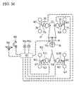
Fig. 36 is a diagram of an electric control system of vehicle 1 shown in
Fig. 26 for controlling step motors 98a and 99a of flow control valves 98 and
99 shown in Fig. 35.
Fig. 37 is a schematic plan view of an alternative four-wheel driving
and steering vehicle 1 having left and right steerable front transaxles 215
(215L and 215R) with respective front wheels 236 and left and right steerable
rear transaxles 213 (213L and 213R) with respective rear wheels 279 when
vehicle 1 is directed straight.
Fig. 38 is a diagram of an alternative steering linkage 18 of vehicle 1
of Fig. 37 including alternative left and right front steering gear trains 217 and
left and right rear steering gear trains 237, when vehicle 1 is directed straight.
Fig. 39 is a sectional rear view of front transaxle 215 (left front
transaxle 215L).
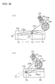
Fig. 40 is a schematic plan view of vehicle 1 shown in Figs. 37 to 39
when vehicle 1 turns left.
Fig. 41 is a sectional rear view of an upper portion of front transaxle
215 shown in Fig. 39, showing a hydraulic motor 210 therein.
Fig. 42 is a sectional rear view of a lower portion of front transaxle 215
shown in Fig. 39, showing a steerable axle housing 228 incorporating a
deceleration gear train 238 and an axle 235.
Fig. 43 is a view of an upper portion of transaxle 215 taken along the
center axis of kingpin portion 227a of a motor housing 227, showing a part of
axle housing 228 relatively rotatably supported on motor housing 227 with a
motor control linkage 243.
Fig. 44 is a cross sectional view of transaxle 215 taken along a XXXIII
- XXXIII line of Fig. 39, showing a part of motor control linkage 243.
Fig. 45(a) is a schematic side view of motor control linkage 243 when
steering wheel 16 is disposed at the straight traveling position.
Fig. 45(a) is a schematic side view of motor control linkage 243 when
steering wheel 16 is fully rotated for turning of vehicle 1.
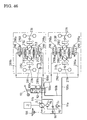
Fig. 46 is a diagram of a hydraulic circuit system of vehicle 1 shown in
Fig. 37 to 44, 45(a) and 45(b), comprising a first hydraulic circuit 289 for the
pair of hydraulic motors 210, a second hydraulic circuit 290 for a pair of
hydraulic motors 280 and the auxiliary speed changing system including
auxiliary speed changing valve 92.
Fig. 47 is a diagram of an alternative second hydraulic circuit 290.
Fig. 48 is a sectional rear view of an alternative front transaxle 215
(left front transaxle 215L), having a large height difference between an axle
331 and a cross member 14.
Fig. 49 is a sectional rear view of a lower portion of front transaxle 215
of Fig. 48, showing an inner structure of a steerable axle housing 328.
Fig. 50 is a schematic plan view of an alternative four-wheel driving
and steering vehicle 1 having steerable front transaxles 215 and steerable rear
transaxles 213, each of which is constructed as shown in Figs. 48 and 49,
when vehicle 1 spins.
Fig. 51 is a schematic plan view of an alternative four-wheel driving
and two-wheel steering vehicle 1 having steering front transaxles 215 and
unsteering rear transaxles 341L and 341R, when vehicle 1 is directed straight.
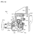
Fig. 52 is a sectional rear view of rear transaxle 341 (left rear transaxle
341L).
Fig. 53 is a schematic plan view of vehicle 1 of Fig. 51, when vehicle 1
turns.
Fig. 54(a) is a schematic side view of motor control linkage 243 of
front transaxle 215 for vehicle 1 of Figs. 51 to 53, when steering wheel 16 is
disposed at the straight traveling position.
Fig. 54(a) is a schematic side view of motor control linkage 243 of
front transaxle 215 for vehicle 1 of Figs. 51 to 53, when steering wheel 16 is
fully rotated for turning of vehicle 1.
Fig. 55 is a diagram of a hydraulic circuit system of vehicle 1 shown in
Fig. 51 to 53, 54(a) and 54(b), comprising first hydraulic circuit 289 for the
pair of hydraulic motors 210, an alternative second hydraulic circuit 350 for a
pair of hydraulic motors 338 and the auxiliary speed changing system
including auxiliary speed changing valve 92.
Fig. 56 is a diagram of an alternative second hydraulic circuit 350.
Fig. 57 is a diagram of an alternative auxiliary speed changing system
including an auxiliary speed changing valve 292 and a deceleration valve 392.
DETAILED DESCRIPTION OF THE INVENTION
A four-wheel driving and two-wheel steering vehicle 1 shown in Figs.
1 to 17 will be described. As shown in Fig. 1, vehicle 1 is provided with a
chassis including right and left side frames 2 supporting right and left front
transaxles 15L and 15R (generically named as "front transaxles 15") and right
and left rear transaxles 13L and 13R (generically named as "rear transaxles
13"), respectively.
In the following description (e.g., about each of transaxles 15 and 13),
terms "proximal" and "distal" are defined with respect to the center of vehicle
1 (and later-discussed various alternative vehicles 1).
Each of front transaxles 15 supports a front wheel 36, and each of rear
transaxles 13 supports a rear wheel 79. Front transaxles 15 are steerably
supported by right and left side frames 2 of the vehicle chassis so that front
wheels 36 serve as steerable wheels. A front cross member 14 is interposed
between right and left front transaxles 15 across side frames 2 so that both
front transaxles 15 are substantially integrally steerable. Rear transaxles 13
are fixedly (unsteerably) supported by right and left side plates 2 so that rear
wheels 79 serve as unsteerable wheels.
Each of rear transaxles 13 incorporates a hydraulic motor 80 for
driving each rear wheel 79, and each of front transaxles 15 incorporates a
hydraulic motor 10 for driving each front wheel 36.
[00100] An engine 3 is disposed between right and left rear wheels 79 and
mounted onto right and left side frames 2 through vibration-isolating rubbers
75, as shown in Fig. 14. A mower 4 is suspended down from the chassis and
incorporates rotary blades 4a disposed between front transaxles 15 and rear
transaxles 13, and drivingly connected to engine 3 so as to drive rotary blades
4a. Mower 4 has a rear-discharging chute 74 extended rearward over engine 3
and a hydraulic pump 5.
[00101] Common variable displacement hydraulic pump 5 for driving all
hydraulic motors 80 and 10 is disposed in vehicle 1 suitably so as to be driven
by engine 3 (via a belt and pulleys, for example). Hydraulic pump 5 has
displacement control means, such as a movable swash plate, interlocking with
a main speed changing pedal 106, as shown in Fig. 15. Alternatively, the
movable swash plate may be electrically controlled by a controller 107 based
on detection of the depression of pedal 106, as shown in Fig. 17.
[00102] As shown in Fig. 15, a first hydraulic circuit 89 including hydraulic
motors 10 of right and left front transaxles 15 is constructed such as to fluidly
connect motors 10 in parallel to hydraulic pump 5 via an auxiliary speed
changing valve 92, and a second hydraulic circuit 90 including hydraulic
motors 80 of right and left front transaxles 13 is constructed such as to fluidly
connect motors 80 to hydraulic pump 5 via auxiliary speed changing valve 92.
Therefore, hydraulic motors 10 differentially drive right and left front wheels
36, and hydraulic motors 80 differentially drive right and left front wheels 79.
[00103] A steering linkage 18 for front wheels 36 will be described. As shown
in Figs. 2 and 3, vehicle 1 includes a steering wheel 16 whose rotational force
is distributed between left and right steering gear trains 17 so as to steer front
wheels 15L and 15R. A stem of steering wheel 16 is inserted into a steering
gearbox 19. A connection rod 20 interposed between input portions of right
and left steering gear trains 17 is drivingly connected to steering gearbox 19 at
a distribution center pivot 21 disposed on the middle point of connection rod
20. Alternatively, a power steering cylinder and a hydraulic control device for
it may be interposed between steering wheel 16 and right and left steering gear
trains 17.
[00104] Referring to Fig. 17, a steering angle sensor 104 is disposed adjacent to
steering wheel 16 so as to detect the rotational angle and direction of steering
wheel 16. Steering angle sensor 104 transmits a detection signal to controller
107.
[00105] As shown in Figs. 2 and 3, each steering gear train 17 includes
mutually meshing sector gears 22 and 30. Sector gear 22 has a toothed distal
edge meshing with sector gear 30, and has a joint pin 24 at its proximal end.
A link rod 25 is pivotally extended from joint pin 24 to each end of connection
rod 20. A pivot shaft 23 of sector gear 22 is disposed between the toothed
distal edge and proximal joint pin 24.
[00106] A kingpin support casing 26 is fixed onto each of right and left ends of
cross member 14. A kingpin sleeve 27 having top and bottom open ends is
coaxially disposed in kingpin support casing 26 so as to be substantially
horizontally rotatable around its substantially vertical center axis. A top
portion of kingpin sleeve 27 projects upward from kingpin support casing 26
so as to be fixedly provided thereon with sector gear 30. Therefore, kingpin
sleeve 27 serves as a pivot shaft of sector gear 30. A bottom portion of
kingpin sleeve 27 projects downward from kingpin support casing 26 so as to
be fixed to a steerable transaxle housing 28 of transaxle 15. Therefore,
transaxle housing 28 of transaxle 15 is rotatable integrally with sector gear 30
and kingpin sleeve 27 relatively to the chassis including side frames 2 and
cross member 14. More specifically, as shown in Figs. 6 and 9, transaxle
housing 28 is formed on the top portion thereof with a mount boss 29, onto
which a bottom flange 27a of kingpin sleeve 27 is fastened so as to open the
inner space of kingpin sleeve 27 into transaxle housing 28.
[00107] As shown in Fig. 2, sector gears 22 and 30 of right and left steering
gear trains 17 are disposed laterally symmetrically when vehicle 1 is directed
straight, i.e., when steering wheel 16 is disposed at its neutral (or straight
traveling) position. When steering wheel 16 is rotated for turning of vehicle 1,
connection rod 20 is tilted so as to rearwardly pull link rod 25 and the
proximal end of sector gear 22 on the turning inside of vehicle 1, and to
forwardly push link rod 25 and the proximal end of sector gear 22 on the
turning outside of vehicle 1. Therefore, mutually meshing toothed edges of
sector gears 22 and 30 on the turning inside of vehicle 1 are rotated forward,
and those on the turning outside of vehicle 1 are rotated rearward.
[00108] A gear ratio between mutually meshing sector gears 22 and 30 is
defined as a ratio of a radius R2 of sector gear 30 to a radius R1 of sector gear
22 between their center pivotal axes. In this regard, radius R1 of sector gear
22 is defined as a distance between the center axis of pivot shaft 23 and its
toothed edge, and radius R2 of sector gear 30 is defined as a distance between
the center axis of kingpin sleeve 27 and its toothed edge. As mutually
meshing toothed edges of sector gears 22 and 33 are rotated forward, the ratio
of radius R2 to radius R1 is reduced so as to increase the increase rate of
turning angle of corresponding wheel 36. As mutually meshing toothed edges
of sector gears 22 and 33 are rotated rearward, the ratio of radius R2 to radius
R1 is increased so as to reduce the increase rate of turning angle of
corresponding wheel 36. Therefore, the turning angle of wheel 36 on the
turning inside of vehicle 1 (hereinafter, "inside wheel 36") becomes larger
than that of wheel 36 on the turning outside of vehicle 1 (hereinafter, "outside
wheel 36"), as shown in Figs. 4 and 5. As the rotational angle of steering
wheel 16 from the neutral position is increased, the difference of turning angle
between inside wheel 36 and outside wheel 36 becomes larger.
[00109] Fig. 5 is a plan view of vehicle 1 when steering wheel 16 is fully
rotated for left turning of vehicle 1. A longitudinal straight line A1 is a center
(laterally middle) line of vehicle 1. A lateral straight line A2 passes the center
axes of right and left kingpin sleeves 27. A lateral straight line A3 is a coaxial
line of right and left rear wheels 79.
[00110] Vehicle 1 is turned right and left by differentially driving unsteerable
rear wheels 79 with hydraulic motors 80 with the assistance of the right and
left turning of steerable front wheels 36. Therefore, the further steering wheel
16 is rotated from the straight traveling position, the more proximally a
turning center 110 of vehicle 1 moves on line A3. When steering wheel 16 is
fully rotated leftward, left rear wheel 79 (left hydraulic motor 80) stops so that
turning center 110 of vehicle 1 is disposed in left rear wheel 79, as shown in
Fig. 5. The turning circle of the center (laterally middle) position of vehicle 1
between front wheels 36 has a radius 111a as a distance between turning
center 110 and a cross point 111 of lines A1 and A2 (which is the middle point
between front wheels 36). The turning circle of the center (laterally middle)
position of vehicle 1 between rear wheels 79 has a radius 112a as a distance
between turning center 110 and a cross point 112 of lines A1 and A3 (which is
the middle point between rear wheels 79).
[00111] Since radius 112a is larger than radius 111a, front wheels 36 are
required to drive faster than rear wheels 79. Additionally, the further steering
wheel 16 is rotated from the straight traveling position, the larger the ratio of
radius 112a to radius 111a becomes. Therefore, hydraulic motors 10 are
automatically controlled to reduce their displacements as steering wheel 16 is
rotated from the straight traveling position.
[00112] Right and left hydraulic motors 10 can reduce their displacements at
the same rate during the turning of steering wheel 16 because fluid from
hydraulic pump 5 is distributed between motors 10 fluidly connected in
parallel to pump 5 so as to allow the differential rotation of inside and outside
wheels 36. Alternatively, the displacement reduction rate of motor 10 for
outside wheel 36 may be larger than that of motor 10 for inside wheel 36 so as
to forcibly drive outside wheel 36 faster than inside wheel 36.
[00113] A structure for steerably supporting transaxle 15 will be described with
reference to Figs. 3 and 6. A joint member 34 is extended upward from the
top of kingpin support casing 26 across sector gear 30. A cap 31 is fastened to
joint member 34 by a bolt so as to cover the open top end of kingpin sleeve 27
above sector gear 30, thereby being fixed to kingpin support casing 26.
[00114] Upper and lower thrust bearings 33a are disposed between the bottom
surface of sector gear 30 and the top surface of kingpin support casing 26, and
between the bottom surface of kingpin support casing 26 and the top surface
of mount boss 27a of kingpin sleeve 27, respectively. Upper and lower
bearings (bushes) 33b are interposed between kingpin support casing 26 and
kingpin sleeve 27 in kingpin support casing 26 adjacent to the top and bottom
open ends of kingpin support casing 26, respectively. Oil seals are interposed
between upper bearings 33a and 33b, and between lower bearings 33a and 33b,
respectively. A retaining ring 32 for retaining sector gear 30 is fitted on
kingpin sleeve 27 between sector gear 30 and cap 31. Due to this construction,
kingpin sleeve 27 and sector gear 30 are stably supported to be rotatable
relative to kingpin support casing 26 and cap 31.
[00115] To remove sector gear 30 from kingpin sleeve 27, the bolt is loosened
and cap 31 is removed from joint member 34, and retaining ring 32 is removed
from kingpin sleeve 27. By the removal of sector gear 30 from kingpin sleeve
27, kingpin sleeve 27 can be easily removed downward from kingpin support
casing 26, thereby facilitating maintenance of kingpin sleeve 27 and transaxle
housing 28 and their interior parts.
[00116] Referring to the interior of kingpin sleeve 27, as shown in Figs. 6, 7, 9
and 10, pipe couplings 46b, 47b and 48b are disposed just above cap 31 and
screwed into cap 31 a, and drain pipe 46 and hydraulic fluid pipes 47 and 48
are substantially axially extended in kingpin sleeve 27 from respective pipe
couplings 46b, 47b and 48b. A brake wire 49 is substantially axially extended
in kingpin support casing 26 while an outer wire of brake wire 49 is retained
on the top surface of cap 31. Brake wire 49 is connected to an unshown
braking manipulator such as a brake pedal. Pipes 46, 47 and 48 are soft and
slightly slackened so that they can be suitably twisted during the rotation of
kingpin sleeve 27 relative to kingpin support casing 26. Kingpin sleeve 27
and kingpin support casing 26 protect such soft pipes 46, 47 and 48 and brake
wire 49 therein, and facilitate the compact arrangement of pipes 46, 47 and 48
and brake wire 49.
[00117] A structure of transaxle 15 will be described. As shown in Figs. 3 and
7, transaxle housing 28 of transaxle 15 comprises an upper housing half 28a
and a lower housing half 28b separably joined to each other through a
horizontal joint surface by bolts 37, on which a center axis of a horizontal axle
35 serving as the center axial shaft of wheel 36 is disposed. Alternatively,
transaxle housing 28 may be constituted by right and left housing halves
joined to each other through a vertical joint surface on which the center axis of
axle 35 is disposed. Axle 35 is journalled at both ends by upper and lower
housing halves 28a and 28b through bearings 67. An end of axle 35 projects
outward from transaxle housing 28 so as to be formed into a hub on which
wheel 36 is mounted.
[00118] In transaxle housing 28 are disposed variable displacement hydraulic
motor 10, a deceleration gear train 38, a brake assembly 39, and a motor
control linkage 40 connected to a movable swash plate 53 of hydraulic motor
10 (for controlling the displacement of motor 10).
[00119] Referring to Fig. 17, rotary speed sensors 102 are disposed adjacent
right and left axles 35 so as to detect the rotary speeds of axles 35, respectively.
Rotary speed sensors 102 transmit detection signals to controller 107.
[00120] Hydraulic motor 10 will be described with reference to Figs. 3, 7 to 9.
In transaxle housing 28, a center section 41 is fastened to upper housing half
28a by upwardly screwed bolts 42. Center section 41 has a horizontal
penetrating hole 43 through which axle 35 is relatively rotatably passed at an
intermediate portion thereof. As shown in Fig. 9, pipe couplings 46a, 47a and
48a of respective pipes 46, 47 and 48 are screwed into the top wall of upper
housing half 28a above center section 41, and vertical ducts 41a and 41b
formed in center section 40 are open upward to be connected to respective
pipe couplings 47a and 48a, thereby preventing fluid from leaking outward
from transaxle housing 28 through ports 46, 47 and 48, and reducing
unexpected influence of hydraulic pressure onto center section 40.
[00121] In center section 41 are formed upper and lower kidney ports 50a and
50b in connection with respective vertical ducts 41a and 41b. Kidney ports
50a and 50b are open at a vertical end surface of center section 41, onto which
a cylinder block 51 is slidably rotatably fitted. A motor sleeve 56 serving as a
motor shaft of hydraulic motor 10 is disposed at the axial center portion of
cylinder block 51, and not-relatively rotatably fitted to cylinder block 51.
Motor sleeve 56 is coaxially and relatively rotatably disposed on axle 35
through bearings (bushes), whereby a distal portion of transaxle housing 28
incorporating hydraulic motor 10 can be so compact as to be disposed in a rim
of wheel 36. Motor sleeve 56 relatively rotatably penetrates center section 41
through penetrating hole 43 and projects outward from center section 41
opposite to cylinder block 51.
[00122] Pistons 52 are axially and reciprocally inserted into cylinder block 51
around motor sleeve 56, thereby constituting hydraulic motor 10 as an axial
piston type. Alternatively, hydraulic motor 10 may be made as a radial piston
type. Heads of pistons 52 project outward from cylinder block 51 opposite to
center section 41 so as to abut against a thrust bearing 54 of movable swash
plate 53. An arcuately recessed guide seat 55 is fixedly fitted to transaxle
housing 28 so as to slidably fit cradle type swash plate 53. Alternatively, a
trunnion type movable swash plate may be used instead of guide seat 55.
[00123] In this way, each of hydraulic motors 10 is individually provided with
kidney ports 50a and 50b, ducts 41a and 41b, pipe couplings 47a and 48a and
pipes 47 and 48 so as to be fluidly connected to hydraulic pump 5. Soft pipes
47 and 48 replace a propeller shaft and other mechanical transmission means
which reduce a space for disposing mower 4 and rear-discharging duct 74.
[00124] As shown in Figs. 3, 7 and 8, deceleration gear train 38 is disposed in a
proximal portion of transaxle housing 28. Deceleration gear train 38 includes
two planetary gear assemblies disposed in parallel and mutually drivingly
connected in tandem. One planetary gear assembly includes a first sun gear 65
and first planetary gears 57, and the other includes a second sun gear 60 and
second planetary gears 61. First sun gear 65 is fixed on the end portion of
motor sleeve 56 projecting outward from center section 41 opposite to
cylinder block 51. First planetary gears 57 are disposed around first sun gear
65 and mesh with it. A ring gear 59 is formed on its outer peripheral surface
with keys 59a fitted into walls of housing halves 28a and 28b so that the outer
peripheral surface of ring gear 59 is not-relatively rotatably fitted to the
surrounding inner surface of transaxle housing 28. Ring gear 59 serves as an
internal gear meshing with first planetary gears 57 and second planetary gears
61 therein.
[00125] First planetary gears 57 are pivoted on a first carrier 58, and second
planetary gears 61 on a second carrier 62. Second carrier 62 is spline-fitted on
an end portion of axle 35 adjacent to bearing 67. Second sun gear 60 is fixed
on axle 35 between second carrier 62 and the end of motor sleeve 56
projecting from center section 41. Second sun gear 60 meshes with an internal
gear formed in first carrier 58, and with second planetary gears 61 disposed
therearound.
[00126] In this way, deceleration gear train 38 is so constructed as to transmit
the rotary force of motor sleeve 56 to axle 35 through first sun gear 65, first
planetary gears 57, second sun gear 60, second planetary gears 61 and second
carrier 62.
[00127] The proximal portion of transaxle housing 28 disposed between wheel
36 and side frame 2 (out of the rim of wheel 36) is expanded so as to have a
radial dimension L2 which is larger than a radial dimension L1 of the distal
portion of transaxle housing 28 incorporating hydraulic motor 10, thereby
ensuring large-sizing of deceleration gear train 38. Due to such a large-sized
deceleration gear train 38, a high-speed and low-torque hydraulic motor can be
used as hydraulic motor 10, i.e., hydraulic motor 10 can be sufficiently small-sized
so as to be disposed in the rim of wheel 36.
[00128] Alternatively, the deceleration gear train interposed between motor
sleeve 56 and axle 35 may use parallel spur gears. Alternatively, the
deceleration gear train may include only one gear assembly, which may
include one sun gear and planetary gears, or include two mutually meshing
spur gears. An alternative deceleration gear train will be discussed later.
[00129] As shown in Figs. 3, 7 and 8, wet disk type brake assembly 39 is
disposed between deceleration gear train 38 and center section 41. Brake
assembly 39 includes a brake disk 66, a pressure plate 64 and a camshaft 63.
Brake disk 66 is spline-fitted onto first sun gear 65 so as to be axially slidable
along first sun gear 66. Vertical camshaft 63 is partly cut away to form a
sectionally semicircular cam whose surface is fitted to pressure plate 64
adjacent to brake disk 66. An brake pad is disposed between ring gear 59 and
brake disk 66. As shown in Fig. 12, camshaft 63 projects upward from
transaxle housing 28 and is fixedly provided thereon with a brake arm 68.
Brake wire 49 is extended from the bottom open end of kingpin sleeve 27 and
connected to brake arm 68. As shown in Fig. 6, brake wire 49 is extended
outward from cap 31 and connected to a brake manipulator, such as a brake
pedal, provided on vehicle 1.
[00130] If camshaft 63 is rotated for braking, the cam surface having been
fitted to pressure plate 64 is slanted so as to press pressure plate 64 against
brake disk 66, thereby clamping brake disk 66 between pressure plate 64 and
the brake pad and braking first sun gear 65 fixed on motor sleeve 56.
[00131] Referring to Figs. 7, 10 to 13, motor control linkage 40 for controlling
movable swash plate 53 interlocks with steering linkage 18 so as to reduce the
displacement of hydraulic motor 10, i.e., increase the output speed of motor 10,
in proportion to increase of the steering angle. As shown in Fig. 7, a vertical
control shaft 69 is rotatably supported by a top wall of the distal portion of
upper housing half 28a. An arm 70 is fixed on a bottom end of control shaft
69 in transaxle housing 28, and fitted into a space between twin upward
projections 53a of swash plate 53 so that swash plate 53 and arm 70 rotate
together with control shaft 69.
[00132] An motor control arm 71 is fixed onto a top end of control shaft 69
projecting upward the top wall of transaxle housing 28. Motor control arm 71
is extended upward, as shown in Fig. 7, and bent to extend a C-like shaped
clamping portion 71a in parallel to the rotational direction of transaxle housing
28 relative to the chassis of vehicle 1. Clamping portion 71 a bifurcates so as
to have two opposite nodular ends 71b, as shown in Fig. 11.
[00133] A peripheral portion of kingpin support casing 26 to be pressed against
nodular ends 71b of motor control arm 71 is formed into a cam 26a as show in
Fig. 10. Four points P1, P2, P3 and P4 are arranged on the periphery of cam
26a counterclockwise so as to divide the peripheral surface of cam 26a into
four substantially quarter ranges. Point P1 is disposed on the front end of cam
26a, and point P3 on the rear end of cam 26a. Points 1 and 3 are disposed on
the basically circular line exactly opposite to each other with respect to a
center axis S of kingpin sleeve 27. Point P2 between points P1 and P3 is
slightly shifted toward point P3 from a point equally distant from points P1
and P3, and opposite point P4 between points P1 and P3 is slightly shifted
toward point P1 from a point equally distant from points P1 and P3. A long
range between points P1 and P2 is equal to that between P3 and P4, and a
short range between points P2 and P3 is equal to that between P4 and P1.
[00134] One of nodular ends 71b slides along the peripheral surface of cam 26a
between points P2 and P4 through point P1, and the other nodular end 71b
between points P2 and P4 through point P3. The long ranges between points
P1 and P2 and between points P3 and P4 serve as slidable ranges for opposite
nodular ends 71b when corresponding wheel 36 turns to the turning inside of
vehicle 1. The short ranges between points P1 and P4 and between points P2
and P3 serve as slidable ranges for opposite nodular ends 71b when
corresponding wheel 36 turns to the turning outside of vehicle 1. Therefore,
the turning angle of transaxle 15 with wheel 36 on the turning inside of vehicle
1 is larger than that on the turning outside of vehicle 1.
[00135] Since illustrated cam 26a is formed for left transaxle 15L, the long
range between P1 and P2 is disposed left, and the short range between P1 and
P4 right. If cam 26a is provided for right transaxle 15R, the long ranges are
exchanged for the short ranges in their right and left positional relation.
[00136] Each of the substantially quarter ranges of cam 26a has a periphery
surface whose distance from center axis S of kingpin sleeve 27 gradually
varies. A basically circular line having a constant radius L3 is drawn in a
phantom line in Fig. 10. During the shift from point P1 to point P2, and from
point P1 to point P4, distance L3 of the peripheral surface of cam 26a is
reduced so as to increase its deviation Δ L from the basically circular line.
During the shift from point P3 to point P2, and from point P3 to point P4,
distance L3 of the peripheral surface of cam 26a is increased so as to increase
its deviation Δ L from the basically circular line. On each of points P2 and P4,
the peripheral surface of cam 26a is curled so as to form a step 26b serving as
a stopper for nodular end 71b.
[00137] As shown in Fig. 13(a), when steering wheel 16 is disposed at the
neutral (straight traveling) position, nodular ends 71b abut against cam 26a on
points P1 and P3. Control shaft 69 revolves integrally with kingpin sleeve 27
and transaxle housing 28 while keeping a constant distance L4 of its center
axis from center axis S of kingpin sleeve 27, as shown in Fig. 11.
[00138] By rotating steering wheel 16 leftward from the straight traveling
position, left transaxle 15L with wheel 36 on the turning inside of vehicle 1
turns leftward so that nodular ends 71b slide along cam 26a in the long ranges
from point P1 to point P2 and from point P3 to point P4. During the sliding of
nodular ends 71b on cam 26a, nodular end 71b on the range between points P1
and P2 moves toward center axis S of kingpin sleeve 27, and nodular end 71b
on the range between points P3 and P4 moves away from center axis S of
kingpin sleeve 27. Finally, nodular end 71b sliding between points P1 and P2
reaches step 26b on point P2, and nodular end 71b sliding between points P3
and P4 reaches step 26b on point P4, as shown in Fig. 13(b), thereby defining
the maximum left (inside) turning angle of left transaxle 15L with wheel 36.
[00139] By rotating steering wheel 16 rightward from the straight traveling
position, left transaxle 15L with wheel 36 on the turning outside of vehicle 1
turns rightward so that nodular ends 71b slide along cam 26a in the short
ranges from point P1 to point P4 and from point P3 to point P2. During the
sliding of nodular ends 71b on cam 26a, nodular end 71b on the range between
points P1 and P4 moves toward center axis S of kingpin sleeve 27, and
nodular end 71b on the range between points P3 and P2 moves away from
center axis S of kingpin sleeve 27. Finally, nodular end 71b sliding between
points P1 and P4 reaches step 26b on point P4, and nodular end 71b sliding
between points P3 and P2 reaches step 26b on point P2, as shown in Fig. 13(c),
thereby defining the maximum right (outside) turning angle of left transaxle
15L with wheel 36.
[00140] The movement of nodular ends 71b depending upon the deviation of
cam 26a from the basically circular line causes the rotation of control shaft 69
fixed to motor control arm 71 relative to transaxle housing 28, thereby moving
swash plate 53. Whether steering wheel 16 is rotated right or left, nodular
ends 71b move in a common direction X arrowed in Fig. 13(b) and Fig. 13(c)
so as to reduce the tilt angle of swash plate 53, i.e., reduce the displacement of
hydraulic motor 10, thereby accelerating wheels 36.
[00141] Deviation rate ΔL of cam 26a in the long range is the same as that in
the short range so that the displacement reduction rate of motor 10, i.e., the
acceleration rate of wheel 36 is the same whether transaxle 15 with wheel 36
is disposed on the turning inside of vehicle 1 or the turning outside of vehicle
1. The natural distribution of fluid between right and left motors 10 fluidly
connected in parallel to hydraulic pump 5 ensures the differential driving of
right and left wheels 36 during the turning of vehicle 1.
[00142] Alternatively, deviation rate ΔL of cam 26a in the long range may be
different from that in the short range so as to forcibly make a difference of
displacement between right and left motors 10 during the turning of vehicle 1.
More specifically, deviation rate Δ L of cam 26a in the long range may be
smaller than that in the short range so that inside wheel 36 becomes slower
than outside wheel 36 during the turning of vehicle 1.
[00143] Referring to Fig. 14, unsteering transaxle 13 with rear wheel 79 will be
described. A transaxle housing 76 of transaxle 13 is disposed on each of right
and left sides of duct 74. An L-like shaped bracket 77 is fastened at its
vertical portion to the vertical surface of side frame 2 by bolts 87, and fastened
at its horizontal portion onto a top surface of housing 76. An upper housing
half 76a and a lower housing half 76b are joined to each other through a
horizontal joint surface by bolts 88 so as to constitute housing 76. An axle 78
is disposed in housing 76 so that the center axis of axle 78 is disposed on the
horizontal joint surface between upper and lower housing halves 76a and 76b.
[00144] In transaxle housing 76, opposite ends of horizontal axle 78 are
journalled by upper and lower housing halves 76a and 76b through respective
bearings 84. The distal end of axle 78 opposite to duct 74 projects outward
from housing 76 so as to be formed into a hub of wheel 79.
[00145] Transaxle housing 76 incorporates a variable displacement hydraulic
motor 80, a deceleration gear train 81, a brake assembly 82 and a motor
control linkage 83 connected to a movable swash plate 73 of motor 80.
Description about deceleration gear train 81, brake assembly 82 and the
structure of motor control linkage 83 in housing 76 is omitted because they are
configured in the same way as deceleration gear train 38, brake assembly 39
and motor control linkage 40 of transaxle 15.
[00146] Hydraulic motor 80 may be fixed in displacement, if possible. In the
present embodiment, variable displacement hydraulic motor 80 has movable
swash plate 53 actuated by an external actuator 101 through linkage 83. As
shown in Fig. 17, controller 107 controls actuators 101 of right and left
transaxles 13R and 13L based on the detection of rotary speeds of right and
left axles 78 by rotary sensors 102 adjacent to respective axles 78.
[00147] A mechanical differential gear assembly may replace the pair of
hydraulic motors 80. Examples of the mechanical differential gear assembly
will be described later with reference to Figs. 18 to 21.
[00148] Alternatively, rear wheels 79 may be steerable according to the
operation of steering wheel 16. An example of a mechanism of steerable rear
wheels 79 will be described later with reference to Fig. 19.
[00149] Transaxle housing 28 of front steering transaxle 15 may serve as
transaxle housing 76 of rear transaxle 13. If transaxle housing 28, provide on
its top with mount boss portion 29, is used as transaxle housing 76 of transaxle
13, mount boss portion 29 is available to steerably support housing 76 onto the
chassis of vehicle 1 in the same way as transaxle housing 28 of transaxle 15.
If transaxle 13 is unsteerably supported, transaxle housing 28 serving as
housing 76 may be fixed to the chassis of vehicle 1 through bracket 77 as
mentioned above.
[00150] A hydraulic circuit system for driving vehicle 1 will be described with
reference to Fig. 15. First hydraulic circuit 89 of transaxles 15L and 15R has a
pair of fluid passages 89a and 89b and respective external ports of passages
89a and 89b so as to fluidly connect hydraulic motors 10 in parallel to
hydraulic pump 5. Hydraulic circuit 90 of transaxles 13L and 13R has a pair
of fluid passages 90a and 90b and respective external ports of passages 90a
and 90b so as to fluidly connect hydraulic motors 80 in parallel to hydraulic
pump 5.
[00151] An auxiliary speed changing valve 92 is interposed between hydraulic
pump 5 and all the external ports of first and second hydraulic circuits 89 and
90 so as to change the fluidal connection pattern of hydraulic motors 10 and
80 to hydraulic pump 5. By manipulation of an auxiliary speed changing
manipulator 93 (such as a pedal or a lever), auxiliary speed changing valve 92
is switched among three positions, i.e., a high speed level position H, a middle
speed level position M and a low speed level position L. A sensor 103 is
disposed adjacent to auxiliary speed changing manipulator 93, and switched
on when auxiliary speed changing manipulator 93 is set for setting auxiliary
speed changing valve 92 at high speed position H.
[00152] Hydraulic pump 5 is provided with a pair of fluid passages 91a and
91b, which are connected to suction and delivery ports of pump 5, respectively.
A charge pump 94 is driven together with hydraulic pump 5 by engine 3.
Fluid from charge pump 94 is supplied to fluid passages 91a and 91b through
respective check valves 96. A relief valve 9 1 a regulates the hydraulic pressure
of fluid from charge pump 94.
[00153] Passage 91a from one port of hydraulic pump 5 bifurcates into
passages 100a and 100b. Passage 100a is connected to the external port of
passage 90a of second hydraulic circuit 90, and passage 100b is connected to
auxiliary speed changing valve 93. A passage 100c is interposed between
auxiliary speed changing valve 93 and the external port of passage 90b of
second hydraulic circuit 90. Passage 91 a from the other port of hydraulic
pump 5 is connected to auxiliary speed changing valve 92. Passages 100d and
100e are interposed between auxiliary speed changing valve 92 and the
respective external ports of passages 89a and 89b of first hydraulic circuit 89.
[00154] Auxiliary speed changing valve 92 set at low speed level position L
bifurcates passage 91b to passages 100c and 100e so as to distribute fluid into
passage 89b of the pair of motors 10 and passage 90b of the pair of motors 80
(or to collect fluid from passage 89b of the pair of motors 10 and passage 90b
of the pair of motors 80). Auxiliary speed changing valve 92 set at low speed
level position L also connects passage 100b to passage 100d. In this way,
when auxiliary speed changing valve 92 is set at low speed level position L,
fluid from hydraulic pump 5 through one of passages 91a and 91b is
distributed between first and second hydraulic circuits 89 and 90 (between
passages 89a and 90a or between passages 89b and 90b), and fluid to
hydraulic pump 5 through the other passage 91b or 91a is collected from first
and second hydraulic circuits 89 and 90 (from passages 89b and 90b or from
passages 89a and 90a). Namely, all hydraulic motors 10 and 80 are fluidly
connected in parallel to hydraulic pump 5, thereby reducing fluid supplied to
each of motors 10 and 80. Vehicle 1 can travel in a four-wheel driving mode
suitably for traction of a heavy machine and climbing a slope.
[00155] Auxiliary speed changing valve 92 set at middle speed level position
M connects passage 91b to passage 100e, i.e., passage 89b of the pair of
motors 10. Auxiliary speed changing valve 92 set at middle speed level
position M also connects passage 100c to passage 100d and shuts off passage
100b. In this way, when auxiliary speed changing valve 92 is set at middle
speed level position M, fluid from hydraulic pump 5 through one of passages
91a and 91b is supplied to one of first and second hydraulic circuits 89 and 90,
and then supplied to the other second or first hydraulic circuit 90 or 89 (from
passage 90a to passage 89b through passages 90b and 89a, or from passage
89b to passage 90a through passages 90b and 89a), and returned to pump 5
through the other passage 91b or 91 a. Namely, the pair of hydraulic motors 10
and the pair of motors 80 are fluidly connected in tandem to hydraulic pump 5,
thereby supplying all the amount of fluid from pump 5 to the pair of motors 10
and to the pair of motors 80. Fluid is distributed between motors 10 and
between motors 80, however, the amount of fluid supplied to each of motors
10 and 80 is larger than that when all motors 10 and 80 are fluidly connected
in parallel to pump 5 during the setting of auxiliary speed changing valve 92 at
low speed level position L. Vehicle 1 can travel in a four-wheel driving mode
suitably for effective work at higher speed than that when auxiliary speed
changing valve 92 is set at low speed level position L.
[00156] Furthermore, when auxiliary speed changing valve 92 is set at middle
position M so as to fluidly connect the pair of motors 10 and the pair of motors
80 in tandem to hydraulic pump 5, and when vehicle 1 travels forward, fluid
from hydraulic pump 5 is supplied to the pair of motors 80 for rear wheels 79
prior to the pair of motors 10 for front wheels 36. Thus, even if vehicle 1
suddenly starts forward and front wheels 36 is intended to rise from the
ground surface, motors 80 supplied with fluid prior to motors 10 can be driven
to ensure the torque of rear wheels 79 for gripping the ground surface, thereby
stabilizing vehicle 1.
[00157] Auxiliary speed changing valve 92 set at high speed level position H
connects passage 91b to passage 100c, i.e., passage 90b of the pair of motors
80. Auxiliary speed changing valve 92 set at high speed level position H also
connects passage 100d to passage 100e and shut off passage 100b. In this way,
when auxiliary speed changing valve 92 is set at high speed level position H,
fluid from hydraulic pump 5 through one of passages 91a and 91b is supplied
to only the pair of motors 80 in second hydraulic circuits 90. Namely, motors
80 are effectively driven with fluid supplied without loss for driving motors 10.
In this way, high speed position H is provided for putting vehicle 1 into a two-wheel
driving mode, while middle and low speed positions M and L are for
putting vehicle 1 into the four-wheel driving mode.
[00158] Due to the connection of passages 100d and 100e, fluid circulates in
first hydraulic circuit 89 isolated from hydraulic pump 5 and second hydraulic
circuit 90, thereby allowing rotation of wheels 36. A check valve 89c supplies
fluid to first hydraulic circuit 89 when first hydraulic circuit 89 is
hydraulically depressed by the circulation of fluid by rotation of wheels 36.
[00159] Furthermore, when auxiliary speed changing valve 92 is set at high
speed position H, sensor 103 is switched on as mentioned above. Based on the
switching on of sensor 103, controller 107 controls external actuator 101 so as
to evenly reduce the tilt angles of movable swash plates 73, i.e., reduce the
displacements of hydraulic motors 80, thereby accelerating wheels 79. In this
way, when auxiliary speed changing valve 92 is set at high speed position H,
vehicle 1 can economically travel at higher speed than the speed of vehicle 1
simply set in the two-wheel driving mode without changing of the
displacement of motors 80.
[00160] Instead of external actuator 101 and sensor 103, linkages 40 with
respective movable swash plates 73 may alternatively interlock with auxiliary
speed changing valve 92 through a mechanical linkage such as a rod or a wire,
so that the tilt angles of movable swash plates 73 are reduced by the setting of
valve 92 at high speed level position H. Alternatively, even if the
displacements of hydraulic motors 80 are not changed, i.e., even if hydraulic
motors 80 are fixed in displacement, the effective driving of motors 80 can be
obtained by the two-wheel driving so as to drive vehicle 1 at a higher speed
level than that of vehicle 1 traveling in the four-wheel driving mode.
[00161] Whichever auxiliary speed changing manipulator 93 is disposed among
the low, middle and high speed level positions, main speed changing pedal
106 is depressed so as to change the displacement and delivery direction of
hydraulic pump 5, thereby changing the traveling speed and direction of
vehicle 1.
[00162] Each of motors 10 and 80 has suction and delivery ports bypassed
through a bypass valve 108. When vehicle 1 is towed, all bypass valves 108
are opened to bypass respective motors 10 and 80. When vehicle 1 is towed,
the force is applied from the ground surface onto wheels 36 and 79 so as to
rotate wheels 36 and 79. However, fluid in hydraulic motors 10 and 80 fluidly
connected to pump 5 resists the rotational force of wheels 36 and 79.
Therefore, bypass valves 108 are opened so that fluid circulates between each
motor 10 or 80 and the corresponding bypass passage without flowing to
hydraulic pump 5, thereby reducing the resistance of fluid. Thus, motors 10
and 80 are allowed to rotate by the force from the ground surface, and wheels
36 and 79 can be freely rotated by the towing of vehicle 1.
[00163] First and second hydraulic circuits 89 and 90 include respective flow
control valves 98 interposed between passage 89b and the pair of motors 10
and between passage 90b and the pair of motors 80. First and second
hydraulic circuits 89 and 90 also include respective flow control valves 99
interposed between passage 89a and the pair of motors 10 and between
passage 90a and the pair of motors 80. In each of flow control valves 98 and
99, each of passages 89b, 90b, 89a and 90a bifurcates to passages connected to
respective motors 10 and 80. Flow control valves 98 and 99 are provided with
respective step motors 98a and 99a for throttling the bifurcating passages from
each of passages 89b, 90b, 89a and 90b. All step motors 98a and 99b are
electrically connected to controller 107.
[00164] It is assumed that, during the forward traveling of vehicle 1, hydraulic
pump 5 delivers fluid to passage 91a and sucks fluid from passage 91b, and
during the backward traveling of vehicle 1, hydraulic pump 5 delivers fluid to
passage 91b and sucks fluid from passage 91a. Flow control valve 99 can be
throttled to restrict the differential rotation of corresponding motors 10 or
motors 80 during the forward traveling of vehicle 1. Flow control valve 98
can be throttled to restrict the differential rotation of corresponding motors 10
or motors 80 during the backward traveling of vehicle 1.
[00165] When vehicle 1 travels forward and either the pair of motors 10 or the
pair of motors 80 need to restrict their differential rotation, corresponding step
motor 99a can be actuated to throttle the bifurcating passages in corresponding
flow control valve 99 from either higher-pressured passage 89a or 90a to the
corresponding pair of motors 10 or 80. During the forward traveling of
vehicle 1, step motor 98a is prevented from actuating, i.e., the bifurcating
passages in each of flow control valves 98 from the corresponding pair of
motors 10 or 80 to each of lower-pressured passages 89b and 90b are not
throttled.
[00166] When vehicle 1 travels backward and either the pair of motors 10 or
the pair of motors 80 need to restrict their differential rotation, corresponding
step motor 98a can be actuated to throttle the bifurcating passages in
corresponding flow control valve 98 from either higher-pressured passage 89b
or 90b to the corresponding pair of motors 10 or 80. During the backward
traveling of vehicle 1, step motor 99a is prevented from actuating, i.e., the
bifurcating passages in each of flow control valves 99 from the corresponding
pair of motors 10 or 80 to each of lower-pressured passages 89a and 90a are
not throttled.
[00167] A differential locking pedal 105 is provided on vehicle 1 for restricting
the differential rotation of motors 10 and 80. Controller 107 controls step
motors 98a and 99a based on detection of sensors, e.g., a sensor adjacent to
differential locking pedal 105, a sensor adjacent to main speed changing pedal
106, rotary speed sensors 102 and steering angle sensor 104. Controller 107
functions extraction and calculation of data and of executing programs. For
example, it may comprise CPU, ROM, RAM, etc. which are mutually
connected by buses, or it may comprise one-chip LSI or the like on having the
above functions.
[00168] For example, when one of right and left front wheels 36 or one of right
and left rear wheels 79 is stuck in a ditch or mud, fluid tends to flow through
motor 10 or 80 of stuck wheel 36 or 79 and motor 10 or 80 of unstuck wheel
36 or 79 is insufficiently supplied with fluid. However, in this state, by
depressing differential locking pedal 105, controller 107 actuates either step
motors 98a or 99a based on the switching on of the sensor adjacent to pedal
105, so as to supply fluid to motor 10 or 80 of unstuck wheel 36 or 79,
whereby vehicle 1 can escape from the ditch or mud. In the case of the
depression of differential locking pedal 105, controller 107 decides whether
step motors 98a or 99a should be actuated depending upon whether main
speed changing pedal 106 is depressed for forward traveling or backward
traveling.
[00169] Controller 107 may control step motors 98a and 99a for stabilizing
turning of vehicle 1 based on detection of rotary speed sensors 102 and
steering angle sensor 104. During the turning of vehicle 1, controller 107
calculates a position of turning center 110, turning radius 112a of rear wheels
79 and turning radius 111a of front wheels 36 (see Fig. 5) based on the
detection of rotational angle of steering wheel 16 by sensor 104. Due to the
calculation of turning radiuses 112a and 111a, all optimal rotary speeds of
respective wheels 36 and 79 are calculated. Based on the detection of rotary
speeds of axles 35 and 78 by sensors 102, if the detected rotary speed of one
wheel 36 or 79 is deviate from its optimal rotary speed, and the wheel 36 or 79
is recognized to be slipping, controller 107 actuates either step motors 98a or
99a so as to restrict the amount of fluid flowing through motor 10 or 80 of
slipping wheel 36 or 79, thereby forcibly supplying fluid to the other motor 10
or 80 of non-slipping wheel 36 or 79. Therefore, vehicle 1 can turn with
constant driving of all wheels 36 and 79 (if auxiliary speed changing valve 92
is set at high speed level position H, with constant driving of both wheels 79).
[00170] When vehicle 1 travels backward, each of step motors 98a is actuated
to throttle the bifurcating passages in corresponding flow control valve 98
from each of higher-pressured passages 89b and 90b, and step motor 99a is not
actuated, i.e., the bifurcating passages in each of flow control valves 99 from
the corresponding pair of motors 10 or 80 to each of lower-pressured passages
89a and 90a are not throttled.
[00171] In the hydraulic circuit system of Fig. 15, first hydraulic circuit 89
includes the pair of parallel-connected motors 10 provided with two flow
control valves 98 and 99 on upstream and downstream sides thereof, and each
of flow control valves 98 and 99 has the variably throttled bifurcating passage
such as to distribute fluid between parallel-connected motors 10 and to collect
fluid from motors 10. Second hydraulic circuit 90 including the pair of
parallel-connected motors 80 is similar. As a result, the entire hydraulic
circuit system including first and second hydraulic circuits 89 and 90 is
provided with four flow control valves 89 and 90 in total.
[00172] Alternatively, as show in Fig. 16 (Fig. 16 illustrates representative
alternative first hydraulic circuit 89), in each of first hydraulic circuits 89 and
90, each motor 10 or 80 may be provided with two flow control valves 109 on
upstream and downstream sides thereof, and each flow control valve 109 may
have a simply linear passage variably throttled by a step motor 109a. As a
result, the hydraulic circuit system including first and second hydraulic
circuits 89 and 90 is provided with eight flow control valves 105.
[00173] Alternative vehicles 1 shown in Figs. 18 to 20 will be described on the
assumption that they are constructed similar to vehicle 1 shown in Figs. 1 to
16 excluding the following features. Especially, the wheelbase and tread are
standardized. Fig. 21 illustrates a drive system shared among vehicles of Figs.
18 to 20. In comparison with vehicle 1 shown in Figs. 1 to 16, description will
be omitted of those parts and structures designated by the same reference
numerals, whose functions are identical.
[00174] Each of alternative vehicles 1 shown in Figs. 18 to 20, having front
steering transaxles 15 (15L and 15R) with front wheels 36, is provided with
left and right rear wheels 119. A rear transaxle 114 is provided for driving
rear wheels 119. A housing 117 of rear transaxle 114 incorporates a single
hydraulic motor 115 and a mechanical differential gear unit 113 (see Fig. 21).
Hydraulic motor 115 in each of vehicles 1 shown in Figs. 18 to 20 is driven by
hydraulic pump 5 so as to drive rear wheels 119 through differential gear unit
113.
[00175] With respect to each of vehicles 1 shown in Figs. 18 and 19, hydraulic
pump 5 for driving hydraulic motor 115 and motors 10 is disposed in housing
117. With respect to vehicle 1 shown in Fig. 20, hydraulic pump 5 for driving
hydraulic motor 115 and motors 10 is disposed out of housing 117 so as to
expand a free space for rear transaxle 114. Pipes are interposed between
separate hydraulic pump 5 and rear transaxle 114 so as to drivingly connect
hydraulic pump 5 to hydraulic motor 115.
[00176] In vehicle 1 shown in Fig. 18, rear transaxle housing 117 is fixed to
side frames 2 of the vehicle chassis. Right and left axles 116 (see Fig. 21) are
differentially connected to each other through differential gear unit 113 in
housing 117, and project outward from housing 117 so as to be fixedly
provided thereon with respective rear wheels 119.
[00177] With respect to vehicle 1 shown in Fig. 18, when steering wheel 16 is
fully rotated for turning, inside rear wheel 119 (rear wheel 119 on the turning
inside of vehicle 1) is stopped and turning center 110 is disposed in inside
wheel 119 so as to ensure turning radius 112a of rear wheels 119 (the distance
between turning center 110 and middle point 112 between right and left rear
wheels 119), that is equal to turning radius 112a of rear wheels 79 of vehicle 1
as shown in Fig. 5. Therefore, steering linkage 18 for steering transaxles 15L
and 15R can be the same as that of vehicle 1 shown in Figs. 1 to 16, so as to
ensure turning radius 111a of wheels 36 which is as long as that of vehicle 1
shown in Fig. 5. Furthermore, the linkage for acceleration of front wheels 36
in association with the turning of vehicle 1 can be the same as that of vehicle 1
shown in Figs. 1 to 16. Especially, the shape of cam 26a formed on kingpin
support casing 26 can be the same as shown in Figs. 10, 11, 13(a), 13(b) and
13(c). As a result, hydraulic motors 10 with respective wheels 36 are
accelerated during the turning of vehicle 1 suitably to the difference between
turning radiuses 111a and 112a.
[00178] Vehicle 1 shown in Fig. 19 is a four-wheel steering vehicle, in which
rear wheels 119 are drivingly and steerably connected to respective axles 116.
Axles 116 project outward through respective side frames 2 from right and left
ends of rear transaxle housing 117, and supported in respective axle casings
123 fixed onto the outside surfaces of side frames 2, thereby constituting right
and left steering wheel support units 122. The turning angle range of rear
wheels 119 is limited so as to prevent rear wheels 119 from abutting against
side frames 2. Steerable rear wheels 119 are linked to each other and
operatively connected to steering wheel 16.
[00179] Due to the linkage between steering wheel 16 and four wheels 36 and
119, while front wheels 36 are turned in agreement with the turning direction
of vehicle 1 (the rotational direction of steering wheel 16), rear wheels 119 are
turned opposite to the turning direction of vehicle 1 so as to reduce the turning
circle of vehicle 1. Turning center 110 is disposed forward from middle point
112 between rear wheels 119 so as to reduce the difference between turning
radius 111a of front wheels 36 and turning radius 112a of rear wheels 119 (and
laterally outside of inside wheel 119, whereby vehicle 1 cannot brake turn by
stopping inside wheel 119). Therefore, the acceleration speed of front wheels
36 must be smaller than that of each of vehicles 1 shown in Figs. 5 and 18. In
this regard, the shape of cam 26a may be changed so as to reduce deviation Δ
L corresponding to the shift angle of movable swash plates 53 of motors 10.
[00180] With respect to vehicle 1 of Fig. 20, right and left rear wheels 119 are
fixed onto respective rear axles 116 extended outward from housing 117 of
rear transaxle 114, similar to Fig. 18. Alternatively, rear wheels 118 may be
steerably connected to axles 116, similar to Fig. 19.
[00181] Referring to Fig. 21, while first hydraulic circuit 89 including
hydraulic motors 10 of front transaxles 15L and 15R is the same as that of Fig.
15, a second hydraulic circuit 120 includes single hydraulic motor 115 of rear
transaxle 114 drivingly connected to rear wheels 119 through mechanical
differential gear unit 113. A pair of passages 120a and 120b are extended
from supply and delivery ports of hydraulic motor 115, and connected to
respective passages 100a and 100c, similar to passages 90a and 90b of
hydraulic motors 80 of rear transaxles 13R and 13L shown in Fig. 15.
[00182] The fluidal connection of hydraulic pump 5 to hydraulic motors 10 and
115 through auxiliary speed changing valve 93 is similar to that shown in Fig.
15. When auxiliary speed changing valve 93 is disposed at low speed level
position L, all three hydraulic motors 10 and 115 are fluidly connected in
parallel to hydraulic pump 5 so as to be supplied with divided fluid. When
auxiliary speed changing valve 93 is disposed at middle speed level position
M, the pair of parallel motors 10 and hydraulic motor 115 are fluidly
connected in tandem to hydraulic pump 5 so as to be supplied with all fluid
delivered from hydraulic pump 5. When auxiliary speed changing valve 93 is
disposed at high speed level position H, only hydraulic motor 115 is fluidly
connected to hydraulic pump 5, and actuator 101 is controlled to reduce the tilt
angle of movable swash plate 121 of motor 115, based on the switching on of
sensor 103, thereby accelerating hydraulic motor 115 and rear wheels 119.
[00183] Alternative transaxle 15 shown in Fig. 22 will be described. In
comparison with transaxle 15 shown in Figs. 3 to 12, description will be
omitted of those parts and structures designated by the same reference
numerals, whose functions are identical.
[00184] A kingpin support casing 141 and a kingpin block 142, relatively
rotatably penetrating kingpin support casing 141, are shorter than
corresponding kingpin support casing 26 and kingpin sleeve 27, so as to
support transaxle housing 28 not below side frame 2 but on lateral outside of
side frame 2. In this regard, a bracket 139 for supporting transaxle housing 28
has a vertical surface fitted onto the vertical outside surface of side frame 2
and fastened to side frame 2 by a bolt or bolts. Bracket 139 has a top portion
139a, which is laterally outwardly extended from the top end of the vertical
surface thereof and fastened to an extended bottom portion of kingpin support
casing 141 by a bolt or bolts.
[00185] Bracket 139 has a bottom portion 139b laterally distally extended from
the bottom end of the vertical surface thereof. A bottom kingpin 140 is
fastened to an outer end of bottom portion 139b and projects upward from the
upper surface of bottom portion 139b coaxially to the center axis of kingpin
block 143. The upward projecting portion of bottom kingpin 140 is relatively
rotatably inserted into a bottom wall of transaxle housing 28. A top portion of
transaxle housing 28 is fixed to a bottom portion of kingpin block 142.
[00186] An upper portion of kingpin block 142 projecting upward from kingpin
support casing 141 is fixedly provided thereon with sector gear 30 so as to
serve as a pivot of sector gear 30. An L-like shaped bracket 138 is fastened at
its vertical surface onto the vertical inside surface of side frame 2 by bolts
138a. A top portion of bracket 138 is bent laterally proximally. Pivot shaft 23
of sector gear 22 projects upward from the top portion of bracket 138. In this
way, according to rotation of mutually meshing sector gears 22 and 30,
kingpin block 142 and transaxle housing 28 are rotated integrally with sector
gear 30 around the center axis of kingpin block 142 and bottom kingpin 140
relative to kingpin support casing 141 and bracket 138.
[00187] Kingpin block 142 is a solid shaft in comparison with hollow kingpin
sleeve 27. In transaxle housing 28 are disposed hydraulic motor 10,
deceleration gear train 38, brake assembly 39, motor control linkage 40 for
controlling movable swash plate 53, and so on, similar to transaxle 15 shown
in Figs. 7 to 9.
[00188] Due to the vertically short transaxle 15, vehicle 1 can be small-sized
and, if side frames 2 are lowered, the gravitational center of vehicle 1 can be
lowered so as to stabilize vehicle 1.
[00189] In comparison with transaxle 15 shown in Fig. 3, the turning range of
transaxle 15 shown in Fig. 22 is restricted by bracket 139. The small-sizing of
vehicle 1 recovers the restriction of turning range of transaxles 15 so as to
reduce the turning circle of vehicle 1.
[00190] Three axial penetrating fluid holes 143, 144 and 145 are formed within
kingpin block 142. Pipe couplings 143a, 144a and 145a are screwed into
bottom openings of respective fluid holes 143, 144 and 145. Drain pipe 46
and hydraulic fluid pipes 47 and 48 are extended downward from respective
pipe couplings 143a, 144a and 145a to pipe couplings 46a, 47a and 48a
screwed into the top surface of transaxle housing 28. Pipe couplings 143b,
144b and 145b are screwed into top openings of respective fluid holes 143,
144 and 145. Hydraulic fluid pipes are extended from pipe couplings 144b
and 145b to hydraulic pump 5, and a drain pipe is extended from pipe
coupling 143b to an unshown fluid tank.
[00191] Brake wire 49 is passed therethrough another axial penetrating hole
formed within kingpin block 142 so as to be connected to a braking
manipulator such as a brake pedal, and to brake arm 68 pivoted above the top
surface of transaxle housing 28 (see Fig. 12).
[00192] Long kingpin sleeve 27 of transaxle 15 shown in Fig. 3 may be
replaced with a solid shaft penetrated by axial holes for passing fluid and
brake wire 49, similar to short kingpin block 142 shown in Fig. 22.
[00193] Referring to Figs. 23 to 25, transaxle 15 including alternative economic
deceleration gear train 38 will be described. A housing 124 incorporating
hydraulic motor 10 is constituted by upper and lower housing halves 124a and
124b joined to each other through a horizontal joint surface on which the
center axis of axle 35 is disposed. Axle 35 is journalled by upper and lower
housing halves 124a and 124b through opposite bearings 67. Horizontal
motor sleeve 56 is coaxially and relatively rotatably fitted on axle 35.
Cylinder block 51 is spline-fitted on motor sleeve 56 and slidably rotatably
fitted onto center section 41. Motor sleeve 56 relatively rotatably penetrates
center section 41, and its proximal end projects outward from center section
41 opposite to cylinder block 51 so as to be fixedly provided thereon with
motor gear 65. A diametrically large gear 149 is fixed (spline-fitted) on axle
35 between the proximal end of motor sleeve 56 and bearing 67 on the
proximal end of axle 35.
[00194] As shown in Fig. 24, a horizontal counter shaft 146 is journalled
between upper and lower housing halves 124a and 124b in parallel to axle 35
through opposite bearings. A long and diametrically small gear 147 is fixed
on counter shaft 146. A gear 148, which is diametrically larger than motor
gear 65, is spline-fitted on gear 147 and meshes with motor gear 65. Gear 149
meshes with gear 147 in parallel to mutually meshing gears 65 and 148. In
this way, deceleration gear train 38 transmits the rotary force of motor sleeve
56 to axle 35 through gears 65, 148, 147 and 149 in order.
[00195] As shown in Fig. 24, alternative brake assembly 39, including a
vertical camshaft 152, a pressure plate 153 and a brake pad 153a, is provided
for braking gear 148. Brake pad 153a is fitted in walls of upper and lower
housing halves 153a opposite to pressure plate 153 with respect to gear 148.
As shown in Fig. 25, camshaft 152 projects upward from housing 124 so as to
be fixedly provided thereon with an arm 151. A brake wire 150 is interposed
between arm 151 and an unshown braking manipulator. By operating the
braking manipulator, camshaft 152 is rotated to press pressure plate 148
against gear 148, thereby braking axle 35.
[00196] In transaxle 15 shown in Figs. 7 and 8, deceleration gear train 38
includes carriers 58 and 62 with planetary gears 57 and 61, and brake
assembly 39 is disposed between deceleration gear train 38 and center section
41, so that the span between motor gear 65 (the first element of deceleration
gear train 38) and carrier 62 (the final element of deceleration gear train 38)
becomes long, thereby axially elongating transaxle 15.
[00197] On the contrary, referring to Figs. 23 and 24, the axial length of
deceleration gear train 38 between motor gear 65 (the first element of
deceleration gear train 38) and gear 149 (the final element of deceleration gear
train 38) is shorter than that of planetary deceleration gear train 38 shown in
Figs. 7 and 8, and brake assembly 39 is disposed in the dead space adjacent to
gear 148 and opposite to gear 149 with respect to gear 147. As a result,
housing 124 is axially shorter than transaxle housing 28 so as to constitute
axially short transaxle 15. Such an axially short transaxle 15 facilitates
steering of vehicle 1, and contributes for small-sizing of vehicle 1. Further,
the parts count and cost of deceleration gear train 38 shown in Fig. 23 and 24
are reduced in comparison with planetary deceleration gear train 38 shown in
Figs. 7 and 8. Such a construction of front transaxle 15, including deceleration
gear train 38 shown in Figs. 23 to 25, is applicable to rear transaxle 13.
[00198] Alternative four-wheel driving and steering vehicle 1 shown in Figs.
26 to 36 will be described. Similar to the above embodiments, left and right
front transaxles 15L and 15R with front wheels 36 are steerably supported by
front cross member 14 on the front end of side frames 2. Further, in this
embodiment, left and right rear transaxles 157L and 157R (generically named
as "rear transaxles 157") with rear wheels 167 (rear wheel 167 on the turning
inside of vehicle 1 is referred to as "inside rear wheel 167", and rear wheel
167 on the turning outside of vehicle 1 is referred to as "outside rear wheel
167") are steerably supported by a rear cross member 156 on the rear end of
side frames 2. Vehicle 1 having steerable front transaxles 15 and rear
transaxles 157 can turn on a very small circle as shown in Fig. 29. Extremely,
it can spin as show in Fig. 30. Transaxle 157 includes a transaxle housing 166
incorporating an axle 164 and a hydraulic motor 165 for driving axle 164.
Rear wheels 167 are fixed on respective axles 164.
[00199] As shown in Fig. 26, vehicle 1 is provided with a front-mount mower
44 in front of the chassis (the front ends of side frames 2). Mower 44 is
drivingly connected to engine 3 through a drive belt 85 for driving its rotary
blades 44a.
[00200] Steering linkage 18 including right and left steering gear trains 17 is
interposed between steering wheel 16 and respective front wheels 36, similar
to Fig. 2. Similar to steering gear trains 17, right and left steering gear trains
155 are interposed between steering wheel 16 and respective rear wheels 167,
as shown in Fig. 27. Front steering gear trains 17 and rear steering gear trains
155 are distributed symmetrically in the longitudinal direction of vehicle 1.
[00201] Right and left steering gear trains 155 are disposed above cross
member 156. As shown in Figs. 27 and 28, each steering gear train 155
includes mutually meshing sector gears 158 and 163. Sector gear 158 has a
toothed distal edge meshing with sector gear 163, and has a joint pin 160 at its
proximal end. Link rods 161 are pivotally extended from respective joint pins
160, cross each other, and are pivotally connected to opposite ends of
connection rod 20. Sector gear 158 is pivoted on a pivot shaft 159 projecting
upward from rear cross member 156 between the toothed distal edge of sector
gear 158 and proximal joint pin 160, as show in Fig. 28.
[00202] A kingpin support casing 162 is fixed onto each of right and left ends
of cross member 156. Kingpin sleeve 27 having top and bottom open ends is
coaxially disposed in kingpin support casing 162 so as to be substantially
horizontally rotatable around its substantially vertical center axis. A top
portion of kingpin sleeve 27 projects upward from kingpin support casing 162
so as to be fixedly provided thereon with sector gear 163. Therefore, kingpin
sleeve 27 serves as the pivot shaft of sector gear 163. A bottom portion of
kingpin sleeve 27 projects downward from kingpin support casing 162 so as to
be fixed to transaxle housing 166 of transaxle 157. Therefore, housing 166 of
transaxle 157 is rotatable integrally with sector gear 163 and kingpin sleeve 27
relatively to the chassis including side frames 2 and cross member 156.
[00203] As shown in Fig. 27, sector gears 158 and 163 of right and left steering
gear trains 155 are disposed laterally symmetrically when vehicle 1 is directed
straight, i.e., when steering wheel 16 is disposed at its neutral (or straight
traveling) position.
[00204] When steering wheel 16 is rotated for turning of vehicle 1, one end of
connection rod 20 on the turning inside of vehicle 1 is rotated rearward so as
to rearwardly pull link rod 25 and the proximal end of sector gear 22 on the
turning inside of vehicle 1, and to rearwardly push link rod 161 and the
proximal end of sector gear 158 on the turning outside of vehicle 1.
Simultaneously, the other end of connection rod 20 on the turning outside of
vehicle 1 is rotated forward so as to forwardly push link rod 25 and the
proximal end of sector gear 22 on the turning outside of vehicle 1, and to
forwardly pull link rod 161 and the proximal end of sector gear 158 on the
turning inside of vehicle 1.
[00205] As a result, as shown in Fig. 29, during the turning of vehicle 1, inside
wheel 36 is turned rearward, inside wheel 167 is turned forward, outside wheel
36 is turned forward, and outside wheel 167 is turned rearward.
[00206] As shown in Fig. 27, mutually meshing sector gears 158 and 163 is so
shaped as to ensure their gear ratio similar to that between mutually meshing
sector gears 22 and 30, as mentioned above. In this regard, the gear ratio of
mutually meshing sector gears 158 and 163 is defined as a ratio of a radius R2
of sector gear 163 to a radius R1 of sector gear 158 on a line between center
axes of pivot shaft 159 and kingpin sleeve 27. Radius R1 of sector gear 158 is
defined as a distance between the center axis of pivot shaft 159 and its toothed
edge, and radius R2 of sector gear 163 is defined as a distance between the
center axis of kingpin sleeve 27 and its toothed edge.
[00207] As mutually meshing toothed edges of sector gears 158 and 163 are
rotated forward, the ratio of radius R2 to radius R1 is increased so as to reduce
the increase rate of the turning angle of corresponding wheel 167. As
mutually meshing toothed edges of sector gears 22 and 33 are rotated rearward,
the ratio of radius R2 to radius R1 is reduced so as to increase the increase rate
of the turning angle of corresponding wheel 167. Therefore, the gear ratio of
inside wheel 167 becomes larger than that of outside wheel 167. As the
rotational angle of steering wheel 16 from the neutral position is increased, the
difference of turning angle between inside wheel 167 and outside wheel 167
becomes larger.
[00208] In this way, the turning angle of forwardly turned inside rear wheel
167 becomes the same as that of rearwardly turned inside front wheel 36, and
the turning angle of rearwardly turned outside rear wheel 167 becomes the
same as that of forwardly turned outside front wheel 36. In other words, as
shown in Fig. 29, turning center 110 is disposed on the longitudinally middle
line of vehicle 1 between middle point 111 of front wheels 36 (cross point 111
between lines A1 and A2) and middle point 112 of rear wheels 167 (cross
point 112 between lines A1 and A3) so that turning radius 112a of rear wheels
167 becomes the same as turning radius 111a of front wheels 36. Namely, the
turning circle of rear wheels 167 agrees with that of front wheels 36 (all
wheels 36 and 167 turn along a common circle).
[00209] When steering wheel 16 is fully rotated for turning of vehicle 1,
turning center 110 reaches middle line A1 so that all wheels 36 and 167 turn
along a common circle centering on the center of vehicle 1, i.e., vehicle 1
spins, as shown in Fig. 30.
[00210] Further, during the turning of vehicle 1, the rotary speed of rear wheels
167 can be as large as that of front wheels 36, whereby change of
displacement of hydraulic motors 10 or 165 is not required to make a
difference between front wheels 36 and rear wheels 167. Therefore, hydraulic
motors 10 and 165 may be fixed in displacement.
[00211] However, to prevent unstable high-speed turning of vehicle 1, front
transaxles 10 incorporate respective variable displacement hydraulic motors
10 with movable swash plates 53, and rear transaxles 157 incorporate
respective variable displacement hydraulic motors 165 with movable swash
plates 171. Motor control linkages 40 of respective transaxles 10 and 157 for
controlling the tilt angles of swash plates 53 and 171 are so constructed as to
increase the tilt angles of swash plates 53 and 171, i.e., to reduce the rotary
speeds of hydraulic motors 10 and 165, according to increase of turning angle
of steering wheel 16.
[00212] Each of front transaxles 15 is provided with an alternative kingpin
support casing 170 formed on an outer peripheral surface thereof with a cam
170a, as shown in Fig. 31. Cam 26a of kingpin support casing 26 shown in
Fig. 10 is shaped so as to reduce the tilt angle of movable swash plate 53
according to increase of turning angle of steering wheel 16. Cam 170a shown
in Fig. 31 is shaped symmetrically in the longitudinal direction of vehicle 1 in
comparison with cam 26a show in Fig. 10.
[00213] As shown in Fig. 31, four points P1, P2, P3 and P4 divide the
peripheral surface of each cam 170a into four substantially quarter ranges,
similar to those of cam 26a shown in Fig. 10. That is, point P1 is the front end
point, and point P3 is the rear end point. Cam 170a has steps 170b on
respective points P2 and P4 such as to serve as stoppers for nodular ends 71b
of clamping portion 71a of motor control arm 71 sliding along the peripheral
surface of cam 170a. The longer ranges between points P1 and P2 and
between points P3 and P4 are provided for sliding of nodular ends 71b of
clamping portion 71a of motor control arm 71 when corresponding wheel 36 is
disposed on the turning inside of vehicle 1. The shorter ranges between points
P2 and P3 and between points P4 and P1 are provided for sliding of nodular
ends 71b of clamping portion 71a of motor control arm 71 when
corresponding wheel 36 is disposed on the turning outside of vehicle 1.
[00214] A basically circular line having constant radius L3 is drawn in a
phantom line in Fig. 31. During the shift from point P1 to point P2, and from
point P1 to point P4, distance L3 of the peripheral surface of cam 170a is
increased so as to increase its deviation from the basically circular line.
During the shift from point P3 to point P2, and from point P3 to point P4,
distance L3 of the peripheral surface of cam 170a is reduced so as to increase
its deviation from the basically circular line.
[00215] Since illustrated cam 170a is formed for left front transaxle 15L, the
long range between P1 and P2 is disposed left, and the short range between P1
and P4 right. If cam 170a is provided for right front transaxle 15R, the long
ranges are exchanged for the short ranges in their right and left positional
relation.
[00216] As shown in Fig. 33(a), when steering wheel 16 is disposed at the
neutral (straight traveling) position, nodular ends 71b abut against cam 170a
on points P1 and P3.
[00217] By rotating steering wheel 16 leftward from the straight traveling
position, left transaxle 15L with wheel 36 on the turning inside of vehicle 1
turns leftward, so that nodular ends 71b slide along cam 170a in the long
ranges from point P1 to point P2 and from point P3 to point P4. During the
sliding of nodular ends 71b on cam 26a, nodular end 71b on the range between
points P1 and P2 moves away from center axis S of kingpin sleeve 27, and
nodular end 71b on the range between points P3 and P4 moves toward center
axis S of kingpin sleeve 27. Finally, nodular end 71b sliding between points
P1 and P2 reaches step 170b on point P2, and nodular end 71b sliding between
points P3 and P4 reaches step 170b on point P4, as shown in Fig. 33(b),
thereby defining the maximum left (inside) turning angle of left transaxle 15L
with wheel 36.
[00218] By rotating steering wheel 16 rightward from the straight traveling
position, left transaxle 15L with wheel 36 on the turning outside of vehicle 1
turns rightward, so that nodular ends 71b slide along cam 26a in the short
ranges from point P1 to point P4 and from point P3 to point P2. During the
sliding of nodular ends 71b on cam 26a, nodular end 71b on the range between
points P1 and P4 moves away from center axis S of kingpin sleeve 27, and
nodular end 71b on the range between points P3 and P2 moves toward center
axis S of kingpin sleeve 27. Finally, nodular end 71b sliding between points
P1 and P4 reaches step 26a on point P4, and nodular end 71b sliding between
points P3 and P2 reaches step 170b on point P2, as shown in Fig. 33(c),
thereby defining the maximum right (outside) turning angle of left transaxle
15L with wheel 36.
[00219] The movement of nodular ends 71b, depending upon the deviation of
cam 26a from the basically circular line, causes the rotation of control shaft 69
fixed to motor control arm 71 relative to transaxle housing 28, thereby moving
swash plate 53. Whether steering wheel 16 is rotated right or left, nodular
ends 71b moves in a common direction Y arrowed in Fig. 33(b) and Fig. 33(c)
so as to increase the tilt angle of swash plate 53, i.e., increase the displacement
of hydraulic motor 10, thereby decelerating front wheels 36.
[00220] Each of rear transaxles 157 is provided with an alternative kingpin
support casing 162 formed on an outer peripheral surface thereof with a cam
162a, as shown in Figs. 28 and 32. Cam 162a shown in Fig. 32 is shaped
laterally symmetrically in comparison with cam 170a show in Fig. 31.
[00221] As shown in Fig. 32, four points P1, P2, P3 and P4 divide the
peripheral surface of each cam 162a into four substantially quarter ranges,
similar to those of cam 170a shown in Fig. 31. Cam 162a has steps 162b on
respective points P2 and P4 such as to serve as stoppers for nodular ends 71b
of clamping portion 71a of motor control arm 71 sliding along the peripheral
surface of cam 162a. The longer ranges between points P1 and P4 and
between points P2 and P3 are provided for sliding of nodular ends 71b of
clamping portion 71a of motor control arm 71 when corresponding wheel 167
is disposed on the turning inside of vehicle 1. The shorter ranges between
points P1 and P2 and between points P3 and P4 are provided for sliding of
nodular ends 71b of clamping portion 71a of motor control arm 71 when
corresponding wheel 167 is disposed on the turning outside of vehicle 1.
[00222] A basically circular line having constant radius L3 is drawn in a
phantom line in Fig. 32. During the shift from point P1 to point P2, and from
point P1 to point P4, distance L3 of the peripheral surface of cam 162a is
increased so as to increase its deviation from the basically circular line.
During the shift from point P3 to point P2, and from point P3 to point P4,
distance L3 of the peripheral surface of cam 162a is reduced so as to increase
its deviation from the basically circular line.
[00223] Since illustrated cam 162a is formed for left rear transaxle 157L, the
long range between P1 and P2 is disposed right, and the short range between
P1 and P4 left. If cam 162a is provided for right rear transaxle 157R, the long
ranges are exchanged for the short ranges in their right and left positional
relation.
[00224] As shown in Fig. 34(a), when steering wheel 16 is disposed at the
neutral (straight traveling) position, nodular ends 71b abut against cam 170a
on points P1 and P3.
[00225] By rotating steering wheel 16 leftward from the straight traveling
position, left transaxle 157L with wheel 167 on the turning inside of vehicle 1
turns rightward, so that nodular ends 71b slide along cam 162a in the long
ranges from point P1 to point P4 and from point P3 to point P2. During the
sliding of nodular ends 71b on cam 162a, nodular end 71b on the range
between points P1 and P4 moves away from center axis S of kingpin sleeve 27,
and nodular end 71b on the range between points P2 and P3 moves toward
center axis S of kingpin sleeve 27. Finally, nodular end 71b sliding between
points P1 and P4 reaches step 162b on point P4, and nodular end 71b sliding
between points P3 and P2 reaches step 162b on point P2, as shown in Fig.
34(b), thereby defining the maximum right (inside) turning angle of left
transaxle 157L with wheel 167.
[00226] By rotating steering wheel 16 rightward from the straight traveling
position, left transaxle 157L with wheel 167 on the turning outside of vehicle
1 turns leftward so that nodular ends 71b slide along cam 162a in the short
ranges from point P1 to point P2 and from point P3 to point P4. During the
sliding of nodular ends 71b on cam 162a, nodular end 71b on the range
between points P1 and P2 moves away from center axis S of kingpin sleeve 27,
and nodular end 71b on the range between points P3 and P4 moves toward
center axis S of kingpin sleeve 27. Finally, nodular end 71b sliding between
points P1 and P2 reaches step 162b on point P2, and nodular end 71b sliding
between points P3 and P4 reaches step 162b on point P4, as shown in Fig.
34(c), thereby defining the maximum right (outside) turning angle of left
transaxle 15L with wheel 36.
[00227] The movement of nodular ends 71b depending upon the deviation of
cam 162a from the basically circular line causes the rotation of control shaft
69 fixed to motor control arm 71 relative to transaxle housing 28, thereby
moving swash plate 171. Whether steering wheel 16 is rotated right or left,
nodular ends 71b moves in a common direction Y arrowed in Fig. 34(b) and
Fig. 34(c) so as to increase the tilt angle of swash plate 171, i.e., increase the
displacement of hydraulic motor 165, thereby decelerating rear wheels 167.
[00228] A hydraulic circuit system for vehicle 1 having front transaxles 15 and
rear transaxles 157 is constructed such as shown in Fig. 35. The hydraulic
circuit system comprises first hydraulic circuit 89 including the pair of parallel
hydraulic motors 10 and an alternative second hydraulic circuit 172 including
the pair of parallel hydraulic motors 165. Second hydraulic circuit 172
includes a hydraulic fluid passage 172a connected to passage 100a, and a
hydraulic fluid passage 172b connected to passage 100c, so as to fluidly
connect hydraulic motors 165 in parallel to hydraulic pump 5 through
auxiliary speed changing valve 92.
[00229] When auxiliary speed changing valve 92 is disposed at low speed level
position L, all hydraulic motors 10 and 165 are fluidly connected in parallel to
hydraulic pump 5 so as to be supplied with respective quarters of fluid from
hydraulic pump 5. When auxiliary speed changing valve 92 is disposed at
middle speed level position M, the pair of parallel hydraulic motors 10 and the
pair of parallel hydraulic motors 165 are fluidly connected in tandem to
hydraulic pump 5 so that all the fluid from hydraulic pump 5 is distributed
between the hydraulic motors 162, and distributed between the hydraulic
motors 10.
[00230] When auxiliary speed changing valve 92 is disposed at high speed
level position H, only the pair of hydraulic motors 165 are supplied with fluid
from hydraulic pump 5. Additionally, the tilt angles of movable swash plates
171 may be reduced so as to increase the rotary speeds of hydraulic motors
165 according to the setting of auxiliary speed changing valve 92 at high
speed level position H.
[00231] Similar to first and second hydraulic circuits 89 and 90 shown in Fig.
15, first and second hydraulic circuits 89 and 172 are provided with flow
control valves 98 and 99 with respective step motors 98a and 99a controlled
by controller 107, according to the rotational angle of steering wheel 16
detected by steering angle sensor 104, the rotary speeds of wheels 36 and 167
detected by respective rotary sensors 102, the traveling direction of vehicle 1
corresponding to the depressed direction of speed control pedal 106, and the
depressed or undepressed state of differential locking pedal 105. Therefore,
the differential rotation of front wheels 36 and the differential rotation of rear
wheels 167 can be suitably restricted.
[00232] An alternative four-wheel driving and steering vehicle 1 shown in Figs.
37 to 50 will be described. Similar to vehicle 1 shown in Fig. 1, vehicle 1
shown in Fig. 37 comprises a vehicle chassis including left and right side
frames 2, engine 3, hydraulic pump 5, mower 4 disposed between front wheels
236 and rear wheels 279. Rear-discharging chute 74 is extended rearward
from mower 4 above engine 3 and hydraulic pump 5. Hydraulic pump 5 is
disposed in front of engine 3 so as to be drivingly connected to engine 3. The
layout of engine 3, mower 4 and hydraulic pump 5 may be changed suitably.
[00233] As shown in Figs. 37 to 40, front cross member 14 is laterally extended
across the front end portions of side frames 2 and pivotally supported at its
laterally middle top portion through a center pin 14a by the chassis so as to be
vertically rotatable at its right and left ends around center pin 14a. Front cross
member 14 steerably supports left and right front transaxles 215L and 215R
(generically named as "front transaxles 215"), each of which incorporates a
hydraulic motor 210 and supports a front wheel 236 driven by hydraulic motor
210. A rear cross member 278 is laterally extended across the rear end
portions of side frames 2. Rear cross member 278 may be also pivotally
supported by the chassis similar to front cross member 14, or may be fixed to
the chassis. Rear cross member 278 steerably supports left and right rear
transaxles 213L and 213R (generically named as "rear transaxles 213"), each
of which incorporates a hydraulic motor 280 and supports a rear wheel 279
driven by hydraulic motor 280.
[00234] Steering linkage 18 shown in Fig. 38 interlockingly connects all
transaxles 215 and 213 to steering wheels 16, similar to steering linkage 18
interlockingly connecting all transaxles 15 and 157 as shown in Fig. 27. Left
and right steering gear trains 217, each of which includes mutually meshing
sector gears 22 and 30, are disposed above front cross member 14, similar to
left and right steering gear trains 17 shown in Figs. 2 and 27. Left and right
steering gear trains 155, each of which includes mutually meshing sector gears
158 and 163, are disposed above rear cross member 278, similar to those
disposed above rear cross member 156 as shown in Fig. 27.
[00235] Description of steering linkage 18 shown in Fig. 38 is omitted because
its structure is the same as steering linkage 18 shown in Fig. 27, excluding that
each of distal sector gears 30 and 163 of transaxles 215 and 213 is relatively
rotatably provided on a later-discussed pivot shaft 231 fixed to each of cross
members 14 and 278, as shown in Fig. 41, in comparison with sector gears 30
and 163 of transaxles 15 and transaxle 157 fixed to rotatable kingpin sleeve 27
(or kingpin block 142).
[00236] Representative left transaxle 215L (hereinafter, transaxle 215) will be
described with reference to Figs. 39, 41 to 44, 45(a) and 45(b). Description of
right transaxle 215R and left and right rear transaxles 213L and 213R is
omitted because they are similar to left transaxle 215L.
[00237] A bracket 226, which is laterally distally open U-like shaped when
viewed in plan as shown in Fig. 37, is fixed onto each of left and right ends of
cross member 14. An upwardly and downwardly open motor housing 227 is
fastened at its front and rear vertical surfaces onto front and rear vertical plate
portions of bracket 226 by bolts or the like. Motor housing 227 has an upper
motor housing portion and a lower kingpin portion 227a which is
diametrically smaller than the upper motor housing portion.
[00238] A hydraulic motor 210 is disposed in the upper motor housing portion
of motor housing 227. A center section 241 of hydraulic motor 210 is fixed
onto a top peripheral edge of motor housing 227 so as to cover the top opening
of motor housing 227. Hydraulic motor 210 is fitted onto the lower surface of
center section 241 and extends a motor shaft 256 downward on the center axis
of kingpin portion 277a of motor housing 227.
[00239] A plate-like stay 229 is extended laterally distally from each of left and
right ends of cross member 14 so as to be fittingly fixed onto the upper surface
of center section 241. A knuckle arm 232 is disposed along the outer surface
of the upper motor housing portion of motor housing 227, and formed on a top
portion thereof with a downwardly open hole 232a. A pivotal shaft 231
projects upward from the top surface of stay 229 so as to be relatively
rotatably inserted into hole 232a. A top surface of knuckle arm 232 is fitted
onto a lower surface of sector gear 30, and sector gear 30 is fastened to
knuckle arm 232 by a bolt. In this way, knuckle arm 232 is rotated integrally
with sector gear 30 around pivot shaft 231. Sector gear 30 meshes with sector
gear 22 pivoted onto cross member 14 through pivot shaft 23 so as to
constitute steering gear train 17.
[00240] A steerable axle housing 228 is disposed below motor housing 227 and
covers kingpin portion 227a of motor housing 227 at its upper portion. A
distal housing half 228a and a proximal housing half 228b are joined to each
other through a ring gear 266 so as to constitute axle housing 228. An upper
portion of proximal housing half 228b is extended upward so as to form a
kingpin casing portion 228c, in which kingpin portion 227a of motor housing
227 is relatively rotatably disposed. Upper and lower bearings 257 are
interposed between an inner peripheral surface of kingpin casing portion 228c
and an outer peripheral surface of kingpin portion 227a. An oil seal 257a is
interposed between the top inner peripheral surface of kingpin casing portion
228c and the stepped outer peripheral surface of motor casing 227 (the upper
end portion of kingpin portion 227a). Knuckle arm 232 is fixed at a bottom
end thereof onto an upper end of kingpin casing portion 228c. In this way,
steerable axle housing 228 is rotated integrally with sector gear 30 and
knuckle arm 232 around kingpin portion 227a and pivot shaft 231.
[00241] Steerable axle housing 228 can be easily detached from motor housing
227 by being removed from knuckle arm 232, thereby facilitating maintenance
or repair of hydraulic motor 210 and parts in motor casing 227 and steerable
axle housing 228.
[00242] Referring to Figs. 39 and 41, hydraulic motor 210 in transaxle 215 will
be more detailed. As shown in Fig. 41, in the upper housing portion of motor
housing 227, a pair of kidney ports 241a are open downward at the bottom
surface of center section 241, and cylinder block 51 is slidably fitted at its top
surface onto the bottom surface of center section 241 in motor housing 227. A
pair of hydraulic fluid ports 241b in connection with respective kidney ports
241a are open outward at a laterally proximal side surface of center section
241 facing cross member 14. Further, a drain port is open outward at the same
side surface of center section 241. Pipe couplings 246a, 247a and 248a are
screwed into the opening ends of the drain port and the pair of hydraulic fluid
ports 241b, respectively. A drain pipe 246 and hydraulic fluid pipes 247 and
248 are extended along cross member 14 and connected to the outer ends of
respective pipe couplings 246a, 247a and 248a. Drain pipe 246 is connected
to an unshown fluid tank, and hydraulic fluid pipes 247a and 248a are
connected to hydraulic pump 5.
[00243] Pistons 51 are axially fitted in cylinder block 51 so as to constitute
axial piston type hydraulic motor 210. A downwardly arcuately recessed
guide seat 55 is fixed on a step between the upper motor housing portion of
motor housing 227 and kingpin portion 227a of motor housing 227. A
movable swash plate 253 with thrust bearing 54 is slidably fitted at its
arcuately convex bottom surface onto the recessed upper surface of guide seat
55.
[00244] Pistons 51 project downward from cylinder block 51 and abut against
thrust bearing 54 in swash plate 253. Alternatively, hydraulic motor 210 may
be a radial piston type hydraulic motor, in which pistons are radially fitted into
its cylinder block. In this construction, a cam ring replacing movable swash
plate 253 may be disposed around the cylinder block so as to abut against the
radial pistons.
[00245] Axial motor shaft 256 of hydraulic motor 210 is extended downward
from cylinder block 51 through swash plate 253 and guide seat 55 on the
center axis of kingpin portion 227a of motor housing 227, journalled by
kingpin portion 227a through upper and lower bearings 233, and inserted into
steerable axle housing 228.
[00246] The inner structure of steerable axle housing 228 will be described
with reference to Figs. 39 and 41. A bottom end of motor shaft 256 projects
downward from lower bearing 233 into a gearing chamber formed in proximal
housing half 228b of steerable axle housing 228 below kingpin casing portion
228c, and is fixedly provided thereon with a bevel motor gear 258. A
horizontal axle 235 is journalled by distal housing half 228b of steerable axle
housing 228 through bearings. A distal end of axle 235 disposed out of
steerable axle housing 228 is formed into a hub 235a of front wheel 236. A
clutch shaft 259 is disposed coaxially to axle 235 and journalled by proximal
housing half 228a through a bearing. A bevel clutch gear 260 is relatively
rotatably provided on clutch shaft 259, and constantly meshes with bevel
motor gear 258.
[00247] A clutch 261 is interposed between clutch gear 260 and clutch shaft
259. In this regard, a spline hub 262a is fixed on clutch shaft 259. A clutch
teeth portion 260a is formed on an end of an axial boss of bevel clutch gear
260 facing spline hub 262a. A clutch slider 262b is spline-fitted on spline hub
262a, and axially slidably shifted between a clutch-on position and a clutch-off
position. Clutch shaft 259 is drivingly connected to axle 235 through a later-discussed
planetary deceleration gear train 238.
[00248] When clutch slider 262b is disposed at the clutch-on position, clutch
slider 262b meshes with clutch teeth portion 260a of clutch gear 260 in
addition to spline hub 262a, the output force of hydraulic motor 210 (the
rotary force of motor shaft 256) is transmitted to clutch shaft 259, thereby
driving front wheel 236. When clutch slider 262b is disposed at the clutch-off
position, clutch slider 262b meshes with only spline hub 262a without clutch
teeth 260a, the output force of hydraulic motor 210 is not transmitted to clutch
slider 262b, thereby stopping front wheel 236.
[00249] Clutch slider 262b, axially slidable on spline hub 262a, is operationally
connected to a clutch manipulator disposed on vehicle 1 out of steerable axle
housing 228. Clutch sliders 262b provided in all front and rear transaxles 215
and 213 may interlock with one another so that all front and rear wheels 236
and 279 can be simultaneously isolated from the driving force caused by
hydraulic fluid supplied from hydraulic pump 5. For example, when vehicle 1
is towed, the clutch manipulator is operated so as to set all clutch sliders 262b
at the clutch-off positions so as to enable all front and rear wheels 236 and 279
to rotate freely from hydraulic motors 210 and 280, thereby preventing
hydraulic motors 210 and 280 from pumping by the rotation of corresponding
wheels 236 and 279.
[00250] A brake assembly 239 is constructed on a proximal end of clutch shaft
259 projecting outward from proximal housing half 228a, and covered with a
cover 228d. In this regard, a brake disk 268 is fixed on the end of clutch shaft
259. A pressure plate 267 is disposed adjacent to brake disk 268. A brake
pad 267a is fitted onto proximal housing half 228a opposite to pressure plate
267 with respect to brake disk 268. A horizontal camshaft 281 is disposed
adjacent to pressure plate 267. Camshaft 281 projects outward from cover
228d and is operationally connected to an unshown brake manipulator. When
the brake manipulator is operated for braking, camshaft 281 is rotated to press
pressure plate 267 against brake disk 268 so as to clamp brake disk 268
between pressure plate 267 and brake pad 267a, thereby braking clutch shaft
259.
[00251] Alternatively, brake assembly 239 may be disposed in another portion
of axle housing 228. Camshafts 281 of brake assemblies 239 in all transaxles
215 and 213 may interlock with one another so as to simultaneously brake all
wheels 236 and 279. Camshafts 281 may be interlockingly connected to
clutch 261 so that clutch 261 is clutched off according to the braking operation
of camshaft 281.
[00252] Planetary gear train 238 is interposed between clutch shaft 259 and
axle 235. As mentioned above, ring gear 266 is fixedly sandwiched between
proximal housing half 228a and distal housing half 228b along a vertical
surface perpendicular to axle 235 and clutch shaft 259. A distal end of clutch
shaft 259 is disposed in ring gear 266 and formed thereon with a sun gear 263.
Ring gear 266 is formed with an internal gear on its inner periphery, and a
planetary gear 264 is (or planetary gears 264 are) interposed between sun gear
263 and the internal gear of ring gear 266. A carrier 265 is fixed on a
proximal end portion of axle 235, and journalled by distal housing half 228b
through a bearing. Planetary gear 264 is (planetary gears 264 are) pivoted on
carrier 238.
[00253] A motor control linkage 243 for controlling swash plate 253 will be
described with reference to Figs. 39, 41, 43, 44, 45(a) and 45(b). A motor
control shaft 269 relatively rotatably penetrates a proximal sidewall of the
upper motor housing portion of motor housing 227. An inner motor control
arm 270 is fixed onto one end of motor control shaft 269 in motor housing 227,
and interlocks with movable swash plate 253. More detailed, a pin projects
from a tip of inner motor control arm 270, and fitted into a recess formed on
movable swash plate 253. Swash plate 253 is a cradle type swash plate, which
slides against seat 55 according to rotation of motor control shaft 269 so as to
rotate around the center axis of motor control shaft 269.
[00254] Motor control linkage 243 is provided for reducing the rotary speed of
hydraulic motor 210 so that vehicle 1 can turn stably. A V-like bent outer
motor control arm 271, whose bent portion is a boss portion fixed on the other
end of motor control shaft 269 on the proximal outside of motor housing 227,
has a first arm portion 271a and a second arm portion 271b extended
substantially perpendicularly to each other from the boss portion thereof fixed
on control shaft 269. A downward rotational direction of first arm portion
271a is defined as the direction of control shaft 269 for increasing the tilt angle
of swash plate 153 (i.e., for increasing the displacement of hydraulic motor
210). First arm portion 271a is arcuately curved when viewed along the center
axis of kingpin portion 227a, as shown in Figs. 43 and 44.
[00255] A top surface of kingpin casing portion 228c of axle housing 228 is
extended outward so as to form a sector portion just below second arm portion
271a. A cam plate 276, which is arcuate when viewed along the center axis of
kingpin portion 227a, is fittingly fixed at its bottom surface onto the top
surface of the sector portion of kingpin casing portion 228c of axle housing
228. Cam plate 276 is sectionally L-like bent to have a plate portion erected
from an outer arcuate edge of the bottom surface. A vertically inversed V-like
shaped cam slot 276a is opened in the erected plate portion of cam plate 276.
[00256] The curvature of first arm portion 271 a agrees with that of the erected
plate portion of cam plate 276 so that first arm portion 271a is fittingly
disposed along the inner surface of the erected plate portion of cam plate 276.
A pin 275 projects from a tip of first arm portion 271a so as to be slidably
inserted into cam slot 276a. The top bent portion of cam slot 276a serves as a
straight traveling position P5 so that, when steering wheel 16 is disposed at the
straight traveling position, pin 275 is disposed at straight traveling position P5
in cam slot 276a, as shown in Fig. 45(a).
[00257] Straight traveling position P5 in cam slot 276a is higher by a height Δ
L than both left and right end positions P6 and P7 in cam slot 276a. As
steering wheel 16 is rotated leftward from the straight traveling position, pin
275 relatively moves from straight traveling position P5 to left end position P6
in cam slot 276a. As steering wheel 16 is rotated rightward from the straight
traveling position, pin 275 relatively moves from straight traveling position P5
to right end position P7 in cam slot 276a. Whether steering wheel 16 is
rotated leftward or rightward from its straight traveling position, pin 275
relatively moves downward in cam plate 276 in the center axial direction of
kingpin portion 227a so as to rotate first arm portion 271 a downward, thereby
increasing the tilt angle of swash plate 253. When steering wheel 16 is fully
rotated, pin 275 reaches either end position P6 or P7 (Fig. 45(b) illustrates pin
275 reaching end position P6 by fully leftward rotation of steering wheel 16),
so that pin 275 is disposed lower than that disposed at straight traveling
position P5 by height Δ L. Fig. 45(b) illustrates a rotational degree X of
motor control shaft 269 corresponding to the motion of pin 275 from position
P5 to position P6 in cam slot 276a.
[00258] Since the turning angle of inside wheel 236 (front wheel 236 on the
turning inside of vehicle 1) is larger than that of outside wheel 236 (front
wheel 236 on the turning outside of vehicle 1), a part of cam slot 276 between
position P5 and one of positions P6 and P7 corresponding to the turning of
inside wheel 236 is longer than the other part of cam slot 275 between position
P5 and the other position P7 or P6 corresponding to the turning of outside
wheel 236. Representative cam slot 276a shown in Fig. 45(a) is provided for
left transaxle 215, so that the left part of cam slot 276a between positions P5
and P6 for sliding of pin 275 during the leftward rotation of steering wheel 16
is longer than the right part of cam slot 276a between positions P5 and P7.
[00259] Second arm portion 271b is provided for returning swash plate 253 and
motor control arms 270 and 271 to their initial positions, i.e., straight traveling
positions. A spring 273 is coiled on the boss portion of outer motor control
arm 271, twisted, and extended at both end portions thereof. As shown in Fig.
45(a), the extended end portions of spring 273 clamp a push pin 272 and a
retaining pin 277 therebetween, when outer motor control arm 271 is disposed
at the initial straight traveling position. Retaining pin 277 is an eccentric pin,
which can be rotated to adjust the straight traveling position of motor control
arms 270 and 271. If first arm portion 271a is rotated downward by rotating
steering wheel 16 from the straight traveling position, as show in Fig. 45(b),
push pin 272 pushes down one end portion of spring 273 while retaining pin
277 retains the other end portion of spring 273 at its initial position, thereby
generating the biasing force of spring 273 for biasing outer motor control arm
271 toward the initial straight traveling position.
[00260] Symmetrical left and right transaxles 215L and 215R are provided with
respective motor control linkages 243 so that the displacement reduction rate
of hydraulic motor 210 in left transaxle 215L is the same as that of hydraulic
motor 210 in right transaxle 215R during the turning operation of steering
wheel 16. However, left and right front wheels 236 can be differentially
rotated during turning of vehicle 1 because of the differential rotation of
parallel hydraulic motors 210 of left and right transaxles 215L and 215R.
[00261] Further, as shown in Fig. 40, since turning radius 111a of front wheels
236 is the same as turning radius 112a of rear wheels 279, left and right
transaxles 213L and 213R are provided with respective motor control linkages
similar to motor control linkages 243 so that the displacement increase rates of
hydraulic motors 280 in rear transaxles 213L and 213R is the same as that of
hydraulic motor 210 in front transaxles 215L and 215R during the turning
operation of steering wheel 16. Left and right rear wheels 279 can be
differentially rotated during turning of vehicle 1 because of the differential
rotation of parallel hydraulic motors 280 of left and right transaxles 213L and
213R.
[00262] Fig. 46 illustrates a hydraulic circuit system for vehicle 1 having front
transaxles 215 and rear transaxles 213 as shown in Figs. 37 to 44, 45(a) and
45(b). The hydraulic circuit system comprises a first hydraulic circuit 289
including the pair of parallel hydraulic motors 210 and a second hydraulic
circuit 290 including the pair of parallel hydraulic motors 280. First hydraulic
circuit 289 includes a hydraulic fluid passage 289a connected to passage 100d,
and a hydraulic fluid passage 289b connected to passage 100e, so as to fluidly
connect hydraulic motors 210 in parallel to hydraulic pump 5 through
auxiliary speed changing valve 92. Second hydraulic circuit 290 includes a
hydraulic fluid passage 290a connected to passage 100a, and a hydraulic fluid
passage 290b connected to passage 100c, so as to fluidly connect hydraulic
motors 280 in parallel to hydraulic pump 5 through auxiliary speed changing
valve 92.
[00263] When auxiliary speed changing valve 92 is disposed at low speed level
position L, all hydraulic motors 210 and 280 are fluidly connected in parallel
to hydraulic pump 5 so as to be supplied with respective almost quarters of
fluid from hydraulic pump 5. When auxiliary speed changing valve 92 is
disposed at middle speed level position M, the pair of parallel hydraulic
motors 210 and the pair of parallel hydraulic motors 280 are fluidly connected
in tandem to hydraulic pump 5 so that all the fluid from hydraulic pump 5 is
distributed between the hydraulic motors 280, and distributed between the
hydraulic motors 210.
[00264] When auxiliary speed changing valve 92 is disposed at high speed
level position H, only the pair of hydraulic motors 280 are supplied with fluid
from hydraulic pump 5. Additionally, the tilt angles of movable swash plates
of hydraulic motors 280 may be reduced so as to increase the rotary speeds of
hydraulic motors 280 according to the setting of auxiliary speed changing
valve 92 at high speed level position H.
[00265] In first hydraulic circuit 289, an electromagnetic switching valve 298 is
interposed between passage 289b and the pair of hydraulic motors 210, and an
electromagnetic switching valve 299 is interposed between passage 289a and
the pair of hydraulic motors 210. In second hydraulic circuit 290, switching
valve 298 is interposed between passage 290b and the pair of hydraulic motors
280, and switching valve 299 is interposed between passage 290a and the pair
of hydraulic motors 280.
[00266] The depression direction of main speed changing pedal 106 (for
forward traveling or backward traveling), interlocking with means for
changing the delivery direction (e.g., a movable swash plate) of hydraulic
pump 5, decides whether hydraulic motors 210 and 280 are supplied with
hydraulic fluid from passages 289a and 290a to respective passages 289b and
290b or from passages 289b and 290b to respective passages 289a and 290a.
When main speed changing pedal 106 is depressed for forward traveling,
hydraulic fluid flows through hydraulic motors 210 from passage 289a to
passage 289b, and through hydraulic motors 280 from passage 290a to passage
290b, so that switching valves 299 are disposed on the upstream of hydraulic
motors 210 and 280, and switching valves 298 on the downstream of hydraulic
motors 210 and 280. When main speed changing pedal 106 is depressed for
backward traveling, hydraulic fluid flows through hydraulic motors 210 from
passage 289b to passage 289a, and through hydraulic motors 280 from passage
290b to passage 290a, so that switching valves 298 are disposed on the
upstream of hydraulic motors 210 and 280, and switching valves 299 on the
downstream of hydraulic motors 210 and 280.
[00267] Each of switching valves 298 and 299 is switched between a normal
position and a differential restriction position. Each of switching valves 298
and 299, set at the differential restriction position, is connected to
corresponding hydraulic motors 210 or 280 through flow restriction member
308, in which a passage from each of switching valves 298 and 299 bifurcates
into two orifices connected to respective hydraulic motors 210 or 280, thereby
restricting the amount of fluid to respective corresponding hydraulic motors
210 or 280, i.e., restricting the differential rotation of corresponding hydraulic
motors 210 or 280. Each of switching valves 298 and 299, set at the normal
position, is connected to the corresponding pair of hydraulic motors 210 or
280 without passing through flow restriction member 308, so as to properly
supply hydraulic fluid to the pair of hydraulic motors 210 or 280, thereby
allowing the proper differential rotation of hydraulic motors 210 or 280.
[00268] Switching valves 298 and 299 are provided with respective solenoids
298a and 299a. By exciting each of solenoids 298 and 299, corresponding
switching valve 298 or 299 is set at the differential restriction position. By
unexciting each of solenoids 298 and 299, corresponding switching valve 298
or 299 is set at the normal position. Solenoids 298 and 299 are excited and
unexcited by a controller based on the operation state of a differential locking
manipulator, such as differential locking pedal 105.
[00269] Whether the differential locking manipulator is operated for
differential restriction or not (whether differential locking pedal 105 is
depressed or not), the pair of switching valves 298 or 299 on the downstream
of the respective pairs of hydraulic motors 210 and 280 are disposed at the
normal positions, so as to collect hydraulic fluid from the respective pairs of
hydraulic motors 210 and 280 without passing through respective flow
restriction members 308.
[00270] When the differential locking manipulator is operated for differential
restriction (differential locking pedal 105 is depressed), the pair of switching
valves 298 or 299 on the upstream of the respective pairs of hydraulic motors
210 and 280 are disposed at the differential restriction positions, so as to
distribute hydraulic fluid to the respective pairs of hydraulic motors 210 and
280 through respective flow restriction members 308, thereby restricting the
differential rotation of front wheels 236 and the differential rotation of rear
wheels 279. When the differential locking manipulator is not operated for
differential restriction (differential locking pedal 105 is not depressed), the
pair of switching valves 298 or 299 on the upstream of the respective pairs of
hydraulic motors 210 and 280 are disposed at the normal positions.
[00271] Alternatively, switching valves 298 and 299 may be removed from one
of first and second hydraulic circuits 289 and 290 so that the differential
rotation of only either the pair of front wheels 236 or the pair of rear wheels
279 can be restricted.
[00272] Fig. 47 illustrates an alternative second hydraulic circuit 290 provided
with an automatically controlled differential restriction means. The flow
direction of hydraulic fluid between passages 290a and 290b, decided
according to the traveling direction of vehicle 1, is the same as the above with
reference to Fig. 46. A three-position flow control valve 309 is interposed
between passage 290a and the pair of hydraulic motors 280. Flow control
valve 309 is disposed on the upstream of hydraulic motors 280 during the
backward traveling of vehicle 1, and on the downstream of hydraulic motors
280 during the forward traveling of vehicle 1.
[00273] Flow control valve 309 is switched among a normal position N, a right
restriction position A, and a left restriction position B. Flow control valve 309
has opposite pilot operation portions receiving pilot pressure fluid from
respective later-discussed switching valves 310L and 310R. When the
opposite pilot pressures are balanced, flow control valve 309 is disposed at
normal position N so as to properly pass fluid between passage 290a and the
pair of hydraulic motors 280. When pilot pressure from right switching valve
310R is higher than that from left switching valve 310L, flow control valve
309 is disposed at right restriction position A so as to restrict flow of fluid to
right hydraulic motor 280 of right transaxle 213R (for right rear wheel 279R)
and to properly pass fluid to left hydraulic motor 280 of left transaxle 213L
(for left rear wheel 279L). When pilot pressure from left switching valve
310L is higher than that from right switching valve 310R, flow control valve
309 is disposed at left restriction position B so as to restrict flow of fluid to
hydraulic motor 280 of left transaxle 213L (for left rear wheel 279L) and to
properly pass fluid to right hydraulic motor 280 of right transaxle 213R (for
right rear wheel 279R).
[00274] Passage 290b bifurcates to hydraulic motors 280 through respective
switching valves 310L and 310R. Switching valves 310L and 310R are
connected together through a connection member 310a, so as to be shifted
integrally with each other. Passage 290b bifurcates, and each of the
bifurcating passages from passage 290b further bifurcates to be connected to
each of valves 310L and 310R. One of bifurcating passages connected to each
of valves 310L and 310R is passed through a check valve, which is opened to
pass fluid from each of valves 310L and 310R to passage 290b when
corresponding valve 310L or 310R supplies pilot pressure fluid to flow control
valve 309. Switching valves 310L and 310R are disposed on the upstream of
hydraulic motors 280 during the forward traveling of vehicle 1, and on the
downstream of hydraulic motors 280 during the backward traveling of vehicle
1.
[00275] Each of switching valves 310L and 310R is switched between a
forward traveling position and a backward traveling position. Switching
valves 310L and 310R have opposite pilot operation portions: one receiving
pilot pressure fluid from passage 290a; and the other receiving pilot pressure
fluid from passage 290b.
[00276] During the backward traveling of vehicle 1, passage 290b is
hydraulically pressured higher than passage 290a so that switching valves
310L and 310R receive pilot pressure from passage 290b to be set at the
backward traveling position, where switching valves 310L and 310R pass
fluid from passage 290b to hydraulic motors 280 so as to allow differential
rotation of hydraulic motors 280. At this time, switching valves 310L and
310R do not generate pilot pressure for shifting flow control valve 309,
whereby flow control valve 309 is disposed at normal position N so as to
collect fluid from hydraulic motors 280 to passage 290a. As a result, rear
wheels 279L and 279R can be properly differentially rotated during the
backward traveling of vehicle 1.
[00277] During the forward traveling of vehicle 1, passage 290a is
hydraulically pressured higher than passage 290b so that switching valves
310L and 310R receive pilot pressure from passage 290a to be set at the
forward traveling position, where each of switching valves 310L and 310R
receives fluid from each of hydraulic motors 280, supplies a part of the fluid
as pilot pressure fluid to flow control valve 309, and supplies the remaining
fluid to passage 290b through the opened check valve.
[00278] If rear wheels 279L and 279R are normally rotated for the forward
traveling of vehicle 1, the opposite pilot pressures to flow control valve 309
are balanced so that flow control valve 309 is disposed at normal position N so
as to properly distribute fluid from passage 290a between hydraulic motors
280.
[00279] If left wheel 279L is ditched and hydraulic motor 280 in left transaxle
213L is excessively supplied with fluid from passage 290a, the pilot pressure
from left switching valve 310L to flow control valve 309 exceeds the pilot
pressure from right switching valve 310R to flow control valve 309, so that
flow control valve 309 is automatically shifted to left restriction position B so
as to restrict the fluid flow to hydraulic motor 280 in left transaxle 280,
thereby supplying sufficient fluid to unditched right wheel 279R, whereby
vehicle 1 can escape from the ditch. Similarly, if right wheel 279R is ditched,
flow control valve 309 is automatically shifted to right restriction position A
so as to restrict hydraulic motor 280 in right transaxle 213R.
[00280] Such automatically controlled differential control means as shown in
Fig. 47 may be applied to first hydraulic circuit 289 including hydraulic
motors 210 of left and right transaxles 215 shown in Fig. 46. Further, it may
be provided to the above-mentioned other vehicles 1.
[00281] Figs. 48 and 49 illustrates an alternative representative transaxle 215
(left front transaxle 215L), which is applicable to right front transaxle 215R
and rear transaxles 213 (left and right rear transaxles 213L and 213R). Fig. 50
illustrates a four-wheel driving and steering vehicle 1 using front and rear
transaxles 215 and 213 of Figs. 48 and 49 when vehicle 1 spins.
[00282] Front transaxle 215 shown in Figs. 48 and 49 has an axle 331, which is
further lowered in comparison with axle 235 of transaxle 215 shown in Fig. 39
so that front wheel 236 fixed onto axle 235 can pass below front cross member
14. Further, rear wheel 279 supported by rear transaxle 213 employing the
same structure of front transaxle 215 shown in Figs. 48 and 49 can pass below
rear cross member 278. As a result, wheels 236 and 279 can be turned in all
directions like casters. Vehicle 1 can spin centering on turning center 110
disposed at the center of vehicle 1 while turning radius 111a of front wheels
236 is equaled to turning radius 112a of rear wheels 279, as shown in Fig. 50.
[00283] Referring to transaxle 215 shown in Figs. 48 and 49, a motor housing
327 incorporating hydraulic motor 210 has a lower kingpin portion 327a
which is longer than kingpin portion 227a of motor housing 227. Motor shaft
256 of hydraulic motor 210 has a length L11 which is longer than that of
motor shaft 256 shown in Fig. 39. To be suitably relatively rotatably
supported on such elongated kingpin portion 327a, a steerable axle housing
328 has a kingpin casing portion 328c, which is longer than kingpin casing
portion 228c of axle housing 228 shown in Fig. 39.
[00284] Further, axle 331 is disposed below a clutch shaft 330, in comparison
with axle 235 disposed coaxially to clutch shaft 259. In this regard, to
constitute axle housing 328, a bearing plate 332 for journaling a distal portion
of clutch shaft 330 through a bearing is sandwiched between a proximal
housing half 328a journaling clutch shaft 330 and a distal housing half 328a
journaling axle 331.
[00285] A deceleration gear train 329 is drivingly interposed between clutch
shaft 330 and axle 331 in distal housing half 328b adjacent to bearing plate
332. Referring to deceleration gear train 329, a diametrically large gear 333 is
fixed onto a proximal end of axle 331 serving as the center axis of
diametrically large gear 333. Diametrically large gear 333 is formed on its
inner peripheral surface with an internal gear 333a. A distal end portion of
clutch shaft 330 is formed into a pinion 330b. Pinion 330b meshes with
internal gear 333a at the top inner peripheral portion of diametrically large
gear 333, so as to ensure a height difference L12 between clutch shaft 330 and
axle 331. Proximal housing half 328a and distal housing half 328b are so
shaped as to suit such deceleration gear train 329.
[00286] Incidentally, axle 331 projects outward from axle housing 328 so as to
be formed into a hub 331a onto which wheel 236 is fixed. Clutch shaft 330 is
drivingly connected to motor shaft 256 through clutch 261 and bevel gears 260
and 258, similar to clutch shaft 259 shown in Fig. 42. Brake assembly 239 is
provided on clutch shaft 330 in axle housing 328, similar to that on clutch
shaft 259 in axle housing 228.
[00287] Other parts of transaxle 215 (213) shown in Figs. 48 to 50 are similar
to those of transaxle 215 shown in Fig. 37 to 46. A hydraulic circuit system of
transaxle 215 and 213 shown in Figs. 48 to 50 may be modified as shown in
Fig. 47.
[00288] An alternative four-wheel driving and two-wheel steering vehicle 1
shown in Figs. 51 to 55, having steerable front wheels 236 and unsteerable
rear wheels 340, will be described. With respect to this vehicle 1, front
transaxles 215 for driving and steering front wheels 236 may be similar to
those shown in Figs. 37 to 42, excluding motor control linkage 243 as shown
in Figs. 54(a) and 54(b), which is different from that shown in Figs 45(a) and
45(b), as discussed later.
[00289] Unsteering rear transaxles 341L and 341R (generically named as "rear
transaxles 341") will be described with reference to Fig. 52 illustrating
representative left transaxle 341L. Transaxle 341 has an unsteerable transaxle
housing 344 disposed on each of left and right outsides of rear-discharging
duct 74 of mower 4, which is extended rearward above engine 3 and hydraulic
pump 5 as shown in Fig. 51. Transaxle housing 344 is constituted by a
proximal housing half 344a and a distal housing half 344b joined to each other
through ring gear 266 of deceleration gear train 238, similar to steerable axle
housing 228. Proximal housing half 344a journals clutch shaft 259, and
incorporates a gear train including clutch 261 and bevel gears 260 and 258 for
drivingly connecting clutch shaft 258 to a vertical motor shaft 346 of a
hydraulic motor 338 of transaxle 341. Brake assembly 239 is disposed in
transaxle housing 344 so as to brake clutch shaft 259, similar to that shown in
Fig. 42. Distal housing half 344b journals an axle 345 disposed coaxially to
clutch shaft 259, similar to axle 235 shown in Fig. 42. Axle 345 projects
outward from axle housing 344 so as to be formed into a hub 345a onto which
rear wheel 340 is fixed. Deceleration gear train 238 including ring gear 266 is
drivingly interposed between clutch shaft 259 and axle 345 in transaxle
housing 344.
[00290] Proximal housing half 344a is formed at an upper portion thereof with
an upwardly open motor housing portion 344c for incorporating hydraulic
motor 338. Center section 241 is fixed onto the top open edge of motor
housing portion 344c. A bracket 342, which is L-like bent when viewed in
rear, is fixed at its vertical surface onto the outside surface of side frame 2, and
at its horizontal bottom surface onto a top surface of center section 241.
[00291] In motor housing portion 344c, hydraulic motor 338 is slidably
rotatably fitted onto a bottom surface of center section 241. A movable swash
plate 339 is fitted onto a bottom surface of motor housing portion 344c. Axial
motor shaft 346 is extended downward from hydraulic motor 338 through
movable swash plate 339 into proximal housing half 344a below motor
housing portion 344c. Bevel motor gear 258 is fixed onto a bottom end of
motor shaft 258 so as to mesh with bevel gear 260 provided on clutch shaft
259.
[00292] As shown in Fig. 53, during turning of vehicle 1, turning radius 111a
of steerable front wheels 236 becomes longer than turning radius 112a of
unsteerable rear wheels 340. Therefore, during turning of vehicle 1, front
wheels 236 (hydraulic motors 210) must be accelerated faster than rear wheels
340 (hydraulic motors 338). Thus, motor control linkage 243 of each front
transaxle 215 must be constructed so as to reduce the tilt angle of swash plate
339 (reduce the displacement of hydraulic motor 338) according to rotation of
steering wheel 16 for turning of vehicle 1, in comparison with motor control
linkage 243 shown in Figs. 41, 43, 44, 45(a) and 45(b) for decelerating
hydraulic motor 210 (or hydraulic motor 280) during turning of vehicle 1.
[00293] Only the different point of steerable linkage 243 shown in Figs. 54(a)
and 54(b) from that shown in Figs. 45(a) and 45(b) is to use a cam plate 376
having a not-reversed V-like shaped cam slot 376a for guiding pin 275
projecting from outer motor control arm 271. In cam slot 376a shown in Figs.
54(a) and 54(b), straight traveling position P5 is lower than both end positions
P6 and P7, in comparison with cam slot 276a shown in Figs. 45(a) and 45(b),
in which straight traveling position P5 is higher than both end positions P6 and
P7. In other words, cam slot 376a corresponds to vertically reversed cam slot
276a.
[00294] By the rotation of steering wheel 16 for turning of vehicle 1, pin 275
relatively moves in cam slot 376a from position P5 to either position P5 or P6,
thereby becoming higher. Accordingly, first arm portion 271a of outer motor
control arm 271 rotates upward so as to reduce the tilt angle of movable swash
plate 339, thereby accelerating hydraulic motor 210 and front wheel 236.
[00295] Fig. 55 illustrates a hydraulic circuit system for vehicle 1 having front
transaxles 215 and rear transaxles 341 as shown in Figs. 51 to 53, 54(a) and
54(b). The hydraulic circuit system comprises first hydraulic circuit 289
including the pair of parallel hydraulic motors 210 and a second hydraulic
circuit 350 including the pair of parallel hydraulic motors 338. First hydraulic
circuit 289 includes hydraulic fluid passage 289a connected to passage 100d,
and hydraulic fluid passage 289b connected to passage 100e, so as to fluidly
connect hydraulic motors 210 in parallel to hydraulic pump 5 through
auxiliary speed changing valve 92. Second hydraulic circuit 350 includes a
hydraulic fluid passage 350a connected to passage 100a, and a hydraulic fluid
passage 350b connected to passage 100c, so as to fluidly connect hydraulic
motors 338 in parallel to hydraulic pump 5 through auxiliary speed changing
valve 92.
[00296] When auxiliary speed changing valve 92 is disposed at low speed level
position L, all hydraulic motors 210 and 338 are fluidly connected in parallel
to hydraulic pump 5 so as to be supplied with respective almost quarters of
fluid from hydraulic pump 5. When auxiliary speed changing valve 92 is
disposed at middle speed level position M, the pair of parallel hydraulic
motors 210 and the pair of parallel hydraulic motors 338 are fluidly connected
in tandem to hydraulic pump 5 so that all the fluid from hydraulic pump 5 is
distributed between the hydraulic motors 338, and distributed between the
hydraulic motors 210.
[00297] When auxiliary speed changing valve 92 is disposed at high speed
level position H, only the pair of hydraulic motors 338 are supplied with fluid
from hydraulic pump 5. Additionally, a sensor 103 is switched on by setting
auxiliary speed changing manipulator 93 for setting auxiliary speed changing
valve 92 at high speed level position H. Accordingly, a controller 301 reduces
the tilt angles of movable swash plates 339 of hydraulic motors 338 so as to
increase the rotary speeds of hydraulic motors 280. Alternatively, hydraulic
motors 338 may be fixed in displacement.
[00298] Similar to first hydraulic circuit 289 and second hydraulic circuit 290
shown in Fig. 46, each of first and second hydraulic circuits 289 and 350 is
provided with electromagnetic switching valves 298 and 299 with respective
flow restriction members 308. More specifically, in second hydraulic circuit
350, switching valve 298 is interposed between passage 350b and the pair of
hydraulic motors 338, and switching valve 299 is interposed between passage
350a and the pair of hydraulic motors 338. As mentioned above, due to
switching valves 298 and 299 controlled based on the depression direction of
speed control pedal 106 and on the operation of a differential restriction
manipulator (such as differential locking pedal 105), hydraulic fluid is
distributed through flow restriction member 308 between hydraulic motors
210 and between hydraulic motors 338 so as to restrict differential rotation of
front wheels 236 and differential rotation of rear wheels 340, at need.
[00299] Alternatively, switching valves 298 and 299 may be removed from one
of first and second hydraulic circuits 210 and 350 so that the differential
rotation of only either the pair of front wheels 236 or the pair of rear wheels
340 can be restricted.
[00300] Fig. 56 illustrates an alternative second hydraulic circuit 350 provided
with an automatically controlled differential restriction means including flow
control valve 309 and switching valves 310L and 310R, similar to Fig. 47.
Description is omitted because the structure and function are the same as that
of Fig. 47.
[00301] Fig. 57 illustrates an alternative auxiliary speed changing system,
which can automatically reduce the speed of vehicle 1 traveling backward.
The auxiliary speed changing system shown in Fig. 57 is applied to the
representative hydraulic circuit system including first and second hydraulic
circuits 289 and 290 as shown in Fig. 46 (or 47). This auxiliary speed
changing system can be applied to any of the hydraulic circuit systems shown
in Figs. 15 (or 16), 21, 35 and 55 (or 56).
[00302] Hydraulic fluid passages 91a and 91b are extended from respective
suction and delivery ports of hydraulic pump 5. Charge pump 94 can supply
fluid to hydraulic fluid passages 91a and 91b through respective charge valves
96. Passage 91a bifurcates to passages 291a and 291b. Passage 291a
bifurcates to passages 300a and 300b. Passage 300a is connected to passage
290a of second hydraulic circuit 290.
[00303] Passages 91b and 291b are connected to an auxiliary speed changing
valve 292 interlocking with an auxiliary speed changing manipulator 293.
Passage 300b is connected to an electromagnetic deceleration valve 392.
Passages 291c, 291d and 291e are interposed between auxiliary speed
changing valve 292 and deceleration valve 392. Passages 300c, 300d and
300e are extended from deceleration valve 392 so that passage 300c is
connected to passage 290b of second hydraulic circuit 290, passage 300d to
passage 289a of first hydraulic circuit 289, and passage 300e to passage 289b
of first hydraulic circuit 289.
[00304] By operating auxiliary speed changing manipulator 293, auxiliary
speed changing valve 292 is switched between a low speed level position L
and a middle speed level position M. Whether auxiliary speed changing valve
292 is disposed at position L or M, vehicle 1 travels by four-wheel driving.
Alternatively, auxiliary speed changing valve 292 can be further shifted to a
high speed level position (such as high speed level position H of valve 92) for
fluidly connecting only either the pair of hydraulic motors 290 or the pair of
hydraulic motors 210 to hydraulic pump 5 so that vehicle 1 can travel by two-wheel
driving.
[00305] Auxiliary speed changing valve 292, disposed at low speed level
position L, connects passage 291b to passage 291c, and bifurcates passage 91b
to passages 291d and 291e, thereby fluidly connecting all hydraulic motors
210 and 280 in parallel to hydraulic motor 5. Auxiliary speed changing valve
292, disposed at middle speed level position M, cuts off passage 291b,
connects passage 91b to passage 291e, and connects passage 291c to passage
291d.
[00306] Deceleration valve 392 is switched between a normal position N and a
deceleration position LO. When deceleration valve 392 is disposed at normal
position N, passage 300b is cut off, passage 291c is connected to passage 300d,
passage 291d is connected to passage 300c, and passage 291e is connected to
passage 300e. When deceleration valve 392 is disposed at deceleration
position LO, passage 300b is connected to passage 300d, passages 291c and
291d are cut off, and passage 291e is bifurcated to passages 300c and 300e.
[00307] Deceleration valve 392 is provided with a solenoid 395 electrically
controlled by a controller 394. A sensor 393 is disposed adjacent to main
speed changing pedal 106 so as to be switched on when main speed changing
pedal 106 is depressed for backward traveling of vehicle 1. When main speed
changing pedal 106 is not depressed, or is depressed for forward traveling of
vehicle 1, sensor 393 is switched off. At this time, solenoid 395 is unexcited
so as to keep deceleration valve 392 at normal position N.
[00308] When auxiliary speed changing valve 292 is disposed at low speed
level position L, and deceleration valve 392 is set at normal position N,
passage 91a from hydraulic pump 5 bifurcates to passages 290a of second
hydraulic circuit 290 and passage 289a of first hydraulic circuit 289, and
passage 91b from hydraulic pump 5 bifurcates to passages 290b of second
hydraulic circuit 290 and passage 289b of first hydraulic circuit 289. As a
result, all hydraulic motors 210 and 280 are fluidly connected in parallel to
hydraulic pump 5.
[00309] When auxiliary speed changing valve 292 is disposed at middle speed
level position M, and deceleration valve 392 is set at normal position N,
passage 91a is connected to passage 290a of second hydraulic circuit 290,
passage 91b is connected to passage 289b of first hydraulic circuit 289, and
passage 290b of second hydraulic circuit 290 is connected to passage 289a of
first hydraulic circuit 289. As a result, the pair of hydraulic motors 210 and
the pair of hydraulic motors 280 are fluidly connected in tandem to hydraulic
pump 5.
[00310] When speed control pedal 106 is depressed for backward traveling of
vehicle 1, sensor 393 is switched on. At this time, if auxiliary speed changing
valve is disposed at middle speed level position M so as to fluidly connect the
pair of hydraulic motors 210 and the pair of hydraulic motors 280 in tandem to
hydraulic pump 5, controller 394 excites solenoid 395 so as to shift
deceleration valve 392 to deceleration position LO, thereby forcibly fluidly
connect all hydraulic motors 210 and 280 in parallel to hydraulic pump 5.
[00311] In this way, even if auxiliary speed changing manipulator 293 is set at
the middle speed level position, all hydraulic motors 210 and 280 are
automatically fluidly connected in parallel to hydraulic pump 5 so as to slow
down vehicle 1 during its backward traveling.
[00312] Although the invention has been described in its preferred form with a
certain degree of particularity, it is understood that the present disclosure of
the preferred form has been changed in the details of construction and the
combination and arrangement of parts may be resorted to without departing
from the spirit and the scope of the invention as hereinafter claimed.