EP1541330B1 - Press machine with a servo-drive system - Google Patents
Press machine with a servo-drive system Download PDFInfo
- Publication number
- EP1541330B1 EP1541330B1 EP03760155A EP03760155A EP1541330B1 EP 1541330 B1 EP1541330 B1 EP 1541330B1 EP 03760155 A EP03760155 A EP 03760155A EP 03760155 A EP03760155 A EP 03760155A EP 1541330 B1 EP1541330 B1 EP 1541330B1
- Authority
- EP
- European Patent Office
- Prior art keywords
- ram
- servo
- servo motors
- punching
- speed
- Prior art date
- Legal status (The legal status is an assumption and is not a legal conclusion. Google has not performed a legal analysis and makes no representation as to the accuracy of the status listed.)
- Expired - Lifetime
Links
- 239000003990 capacitor Substances 0.000 claims abstract description 11
- 230000001629 suppression Effects 0.000 claims abstract description 4
- 238000004080 punching Methods 0.000 claims description 88
- 238000004804 winding Methods 0.000 claims description 6
- 239000002131 composite material Substances 0.000 claims description 3
- 230000007246 mechanism Effects 0.000 description 16
- 238000010586 diagram Methods 0.000 description 13
- 230000009467 reduction Effects 0.000 description 11
- 238000000605 extraction Methods 0.000 description 9
- 230000005540 biological transmission Effects 0.000 description 7
- 230000005611 electricity Effects 0.000 description 7
- 230000033001 locomotion Effects 0.000 description 6
- 239000000463 material Substances 0.000 description 6
- 230000001133 acceleration Effects 0.000 description 5
- 230000009471 action Effects 0.000 description 5
- 238000007796 conventional method Methods 0.000 description 4
- 230000003247 decreasing effect Effects 0.000 description 4
- 230000001172 regenerating effect Effects 0.000 description 4
- 230000002411 adverse Effects 0.000 description 3
- 230000003111 delayed effect Effects 0.000 description 2
- 230000004044 response Effects 0.000 description 2
- 230000002441 reversible effect Effects 0.000 description 2
- 230000008859 change Effects 0.000 description 1
- 230000000295 complement effect Effects 0.000 description 1
- 238000001816 cooling Methods 0.000 description 1
- 230000001934 delay Effects 0.000 description 1
- 230000001419 dependent effect Effects 0.000 description 1
- 239000000314 lubricant Substances 0.000 description 1
Images


Classifications
-
- B—PERFORMING OPERATIONS; TRANSPORTING
- B30—PRESSES
- B30B—PRESSES IN GENERAL
- B30B15/00—Details of, or accessories for, presses; Auxiliary measures in connection with pressing
- B30B15/14—Control arrangements for mechanically-driven presses
- B30B15/148—Electrical control arrangements
-
- B—PERFORMING OPERATIONS; TRANSPORTING
- B30—PRESSES
- B30B—PRESSES IN GENERAL
- B30B1/00—Presses, using a press ram, characterised by the features of the drive therefor, pressure being transmitted directly, or through simple thrust or tension members only, to the press ram or platen
-
- B—PERFORMING OPERATIONS; TRANSPORTING
- B30—PRESSES
- B30B—PRESSES IN GENERAL
- B30B1/00—Presses, using a press ram, characterised by the features of the drive therefor, pressure being transmitted directly, or through simple thrust or tension members only, to the press ram or platen
- B30B1/26—Presses, using a press ram, characterised by the features of the drive therefor, pressure being transmitted directly, or through simple thrust or tension members only, to the press ram or platen by cams, eccentrics, or cranks
- B30B1/266—Drive systems for the cam, eccentric or crank axis
-
- B—PERFORMING OPERATIONS; TRANSPORTING
- B30—PRESSES
- B30B—PRESSES IN GENERAL
- B30B15/00—Details of, or accessories for, presses; Auxiliary measures in connection with pressing
- B30B15/14—Control arrangements for mechanically-driven presses
-
- Y—GENERAL TAGGING OF NEW TECHNOLOGICAL DEVELOPMENTS; GENERAL TAGGING OF CROSS-SECTIONAL TECHNOLOGIES SPANNING OVER SEVERAL SECTIONS OF THE IPC; TECHNICAL SUBJECTS COVERED BY FORMER USPC CROSS-REFERENCE ART COLLECTIONS [XRACs] AND DIGESTS
- Y10—TECHNICAL SUBJECTS COVERED BY FORMER USPC
- Y10T—TECHNICAL SUBJECTS COVERED BY FORMER US CLASSIFICATION
- Y10T74/00—Machine element or mechanism
- Y10T74/18—Mechanical movements
- Y10T74/18056—Rotary to or from reciprocating or oscillating
- Y10T74/18248—Crank and slide
-
- Y—GENERAL TAGGING OF NEW TECHNOLOGICAL DEVELOPMENTS; GENERAL TAGGING OF CROSS-SECTIONAL TECHNOLOGIES SPANNING OVER SEVERAL SECTIONS OF THE IPC; TECHNICAL SUBJECTS COVERED BY FORMER USPC CROSS-REFERENCE ART COLLECTIONS [XRACs] AND DIGESTS
- Y10—TECHNICAL SUBJECTS COVERED BY FORMER USPC
- Y10T—TECHNICAL SUBJECTS COVERED BY FORMER US CLASSIFICATION
- Y10T74/00—Machine element or mechanism
- Y10T74/19—Gearing
- Y10T74/19023—Plural power paths to and/or from gearing
- Y10T74/19051—Single driven plural drives
- Y10T74/19056—Parallel
-
- Y—GENERAL TAGGING OF NEW TECHNOLOGICAL DEVELOPMENTS; GENERAL TAGGING OF CROSS-SECTIONAL TECHNOLOGIES SPANNING OVER SEVERAL SECTIONS OF THE IPC; TECHNICAL SUBJECTS COVERED BY FORMER USPC CROSS-REFERENCE ART COLLECTIONS [XRACs] AND DIGESTS
- Y10—TECHNICAL SUBJECTS COVERED BY FORMER USPC
- Y10T—TECHNICAL SUBJECTS COVERED BY FORMER US CLASSIFICATION
- Y10T74/00—Machine element or mechanism
- Y10T74/19—Gearing
- Y10T74/19642—Directly cooperating gears
- Y10T74/19698—Spiral
-
- Y—GENERAL TAGGING OF NEW TECHNOLOGICAL DEVELOPMENTS; GENERAL TAGGING OF CROSS-SECTIONAL TECHNOLOGIES SPANNING OVER SEVERAL SECTIONS OF THE IPC; TECHNICAL SUBJECTS COVERED BY FORMER USPC CROSS-REFERENCE ART COLLECTIONS [XRACs] AND DIGESTS
- Y10—TECHNICAL SUBJECTS COVERED BY FORMER USPC
- Y10T—TECHNICAL SUBJECTS COVERED BY FORMER US CLASSIFICATION
- Y10T74/00—Machine element or mechanism
- Y10T74/20—Control lever and linkage systems
- Y10T74/20207—Multiple controlling elements for single controlled element
- Y10T74/20341—Power elements as controlling elements
- Y10T74/2036—Pair of power elements
-
- Y—GENERAL TAGGING OF NEW TECHNOLOGICAL DEVELOPMENTS; GENERAL TAGGING OF CROSS-SECTIONAL TECHNOLOGIES SPANNING OVER SEVERAL SECTIONS OF THE IPC; TECHNICAL SUBJECTS COVERED BY FORMER USPC CROSS-REFERENCE ART COLLECTIONS [XRACs] AND DIGESTS
- Y10—TECHNICAL SUBJECTS COVERED BY FORMER USPC
- Y10T—TECHNICAL SUBJECTS COVERED BY FORMER US CLASSIFICATION
- Y10T83/00—Cutting
- Y10T83/869—Means to drive or to guide tool
- Y10T83/8726—Single tool with plural selective driving means
-
- Y—GENERAL TAGGING OF NEW TECHNOLOGICAL DEVELOPMENTS; GENERAL TAGGING OF CROSS-SECTIONAL TECHNOLOGIES SPANNING OVER SEVERAL SECTIONS OF THE IPC; TECHNICAL SUBJECTS COVERED BY FORMER USPC CROSS-REFERENCE ART COLLECTIONS [XRACs] AND DIGESTS
- Y10—TECHNICAL SUBJECTS COVERED BY FORMER USPC
- Y10T—TECHNICAL SUBJECTS COVERED BY FORMER US CLASSIFICATION
- Y10T83/00—Cutting
- Y10T83/869—Means to drive or to guide tool
- Y10T83/8821—With simple rectilinear reciprocating motion only
- Y10T83/8841—Tool driver movable relative to tool support
- Y10T83/8843—Cam or eccentric revolving about fixed axis
-
- Y—GENERAL TAGGING OF NEW TECHNOLOGICAL DEVELOPMENTS; GENERAL TAGGING OF CROSS-SECTIONAL TECHNOLOGIES SPANNING OVER SEVERAL SECTIONS OF THE IPC; TECHNICAL SUBJECTS COVERED BY FORMER USPC CROSS-REFERENCE ART COLLECTIONS [XRACs] AND DIGESTS
- Y10—TECHNICAL SUBJECTS COVERED BY FORMER USPC
- Y10T—TECHNICAL SUBJECTS COVERED BY FORMER US CLASSIFICATION
- Y10T83/00—Cutting
- Y10T83/869—Means to drive or to guide tool
- Y10T83/8821—With simple rectilinear reciprocating motion only
- Y10T83/8841—Tool driver movable relative to tool support
- Y10T83/8844—Gear actuated tool support
Abstract
Description
- The present invention relates to a press machine with a servo drive system. A press machine with a servo drive system comprising a ram; an operation shaft which vertically moves the ram can be taken from the prior art document
US 5,832,816 , which discloses a press machine in accordance with the preamble ofclaim 1. Said prior art system comprises a pair of servo motors which operate as power sources of the ram and which composite and use torques based on the same speed-torque characteristics, thereby generating necessary ram pressure. Said pair of servo motors are opposed to each other at opposite ends of the operation shaft, and the pair of servo motors are operated so that the pair of servo motors directly drive the operation shaft to vertically move the ram. - Conventionally, there are electric punch presses using a servo motor as a driving source of a ram. In punching working of a press machine such as a punch press, since extremely large noise is generated during the working, it is required to decrease this kind of noise as small as possible.
- Principles of generation of noise in the punching working are complicated, and reasons of generation of noise are varied depending upon various conditions such as the material of the work, the plate 0thickness, and the like. However, it is known that the noise is large when the punching speed by driving of a ram is fast, the noise becomes smaller when the punching speed becomes slower, and when the punching speed is constant, the noise is small when the load is light, and as the load becomes heavier, the noise becomes larger.
- The above conventional technique is disclosed in Japanese Patent Applications Laid-Open Nos.
2001-62591 2001-62596 - However, the conventional electric punch press generates a torque necessary for working by using a mechanism such as a toggle and a flywheel. Therefore, the inertia caused by this mechanism delays the reciprocating motion of the ram. In addition, an operation shaft which vertically moves the ram and a main shaft of a servo motor is driven through a power transmission mechanism such as a gear, and a loss or a delay is generated by the power transmission mechanism. Even if the speed of the servo motor is controlled, the driving speed of the ram can not follow the speed of the servo motor easily, and therefore the conventional technique is not suitable for controlling the speed of the ram.
- For this reason, the conventional technique has problems that since the punching speed is set substantially at a constant value irrespective of the weight of the load, if the punching speed is set lower to decrease the noise, the operation efficiency is largely deteriorated, and if the punching speed is set higher to enhance the operation efficiency, a large noise is generated and thus, reduction of noise and enhancement of operation efficiency can not be satisfied at the same time.
- According to the conventional system, a predetermined punching pattern is switched in a hydraulic press system depending upon the plate thickness, material, and the like to satisfy both the noise reduction and increase of punching speed. Therefore, complicated control systems such as high-speed processing hardware and software are required.
- Generally, there are a hydraulic punch press using hydraulic pressure as the driving source of the ram and an electric punch press using a servo motor. In the punch press, the same punching die such as a nibble is used and a work is continuously punched in some cases. In such a continuous punching working, a speedup of the ram is required.
- In the conventional hydraulic punch press, however, since the ram is reciprocated using a hydraulic pressure and a switching valve, response speed is inferior to that of the electric control, and a response delay to the control command is generated and thus, the conventional hydraulic punch press is not suitable for speedup of the ram.
- Further, the conventional technique has problems that since the punching speed is set substantially at a constant value irrespective of the weight of the load, if the punching speed is set lower to decrease the noise, the operation efficiency is largely deteriorated, and if the punching speed is set higher to enhance the operation efficiency, a large noise is generated and thus, reduction of noise and enhancement of operation efficiency can not be satisfied at the same time.
- It is assumed herein to drive the operation shaft which vertically moves the ram, directly by the servo motor without through a power transmission mechanism such as a gear and without using a mechanism such as a toggle and a flywheel. If the operation shaft is driven directly by the servo motor, there is a possibility that the punching speed can automatically be increased or decreased according to the load, and with this, there is a possibility that both the noise reduction and the enhancement of operation efficiency can be satisfied at the same time.
- If a case where a mechanism such as a toggle and a flywheel is used for generating a torque necessary for the working and a case where the mechanism is not used (direct driving by the servo motor) are compared with each other, in the punching working using the punch press, since a large punching energy is required at the time of the punching working in addition to the kinetic energy for vertically moving the ram at high speed, a servo motor having a greater rating is required in the direct driving.
- In order to drive the operation shaft which vertically moves the ram directly by the servo motor, it is necessary to supply, to the servo motor, electric energy for high speed operation and for punching working, and a peak electricity of a control circuit for the servo motor becomes extremely high.
- It is an object of the present invention to provide a press machine with a servo drive system which can decrease a noise by automatically increasing and decreasing punching speed according to a load without using a mechanism such as a toggle or flywheel, and without using a power transmission mechanism such as a gear, and which can prevent mechanical portions corresponding to one side of the operation shaft from being distorted, and realize stabilized operation.
- According to the present invention, said objective is solved by a press machine with a servo drive system having the features of
independent claim 1. Preferred embodiments are laid down in the dependent claims. - It is provided a servo drive system of a press machine which can decrease a noise and enhance the operation efficiency at the same time by automatically increasing and decreasing the punching speed according to a load.
- It is also provided a continuous working system of a press machine in which transmission of a driving force is not delayed in principle, control delay is not generated, responding speed is high, and operation speed is high, while using a servo motor as a driving source of a ram without using a mechanism such as a toggle and a flywheel and a power transmission mechanism such as a gear.
- It is also provided a servo drive system of a punch press which can decrease a noise and enhance the operation efficiency at the same time by automatically increasing and decreasing the punching speed according to a load, and reduce a peak electricity of a control circuit for the servo motor.
- According to the servo drive system, since the operation shaft is directly driven by using the pair of servo motors which can generate necessary ram pressure, a mechanism such as a toggle and a flywheel as well as a power transmission mechanism such as a gear are not used and thus, the punching speed can automatically be increased or reduced according to the load.
- Further, a noise can be reduced, a distortion is prevented from being generated in various portions of the machine corresponding to one side of the operation shaft, and stable operation can be realized.
- Hereinafter, the present invention is illustrated and explained by means of a preferred embodiment in conjunction with the accompanying drawings. In the drawings wherein:
-
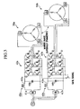
Fig. 1 is a vertical sectional view of an essential portion showing an embodiment of a servo drive system (continuous working system) of a press machine according to the present invention; -
Fig. 2 is a right side view of an essential portion shown inFig. 1 ; -
Fig. 3 is a connection diagram showing an example of a structure of a servo motor shown inFig. 1 and a servo amplifier which drives the servo motor; -
Figs. 4A, 4B, and 4C are explanatory views showing an operation region of an eccentric shaft portion (ram) of an eccentric shaft; -
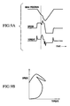
Fig. 5 is a graph showing an example of speed-torque characteristics of the servo motor; -
Fig. 6 is a diagram showing actually measured data of a punching working when there is no work; -
Fig. 7A is a diagram showing feature extraction waveform data based on the actually measured data shown inFig. 6 ; -
Fig. 7B is a diagram showing punching torque-speed characteristics based on the actually measured data shown inFig. 6 ; -
Fig. 8 is a diagram showing actually measured data of a punching working when a thin plate work is punched out using a punch having a small diameter; -
Fig. 9A is a diagram showing the feature extraction waveform data based on the actually measured data shown inFig. 8 ; -
Fig. 9B is a diagram showing punching torque-speed characteristics based on the actually measured data shown inFig. 8 ; -
Fig. 10 is a diagram showing actually measured data of a punching working when a thin plate work is punched out using a punch having a large diameter; -
Fig. 11A is a diagram showing the feature extraction waveform data based on the actually measured data shown inFig. 10 ; -
Fig. 11B is a diagram showing the punching torque-speed characteristics based on the actually measured data shown inFig. 10 ; -
Fig. 12 is a diagram showing actually measured data of a punching working when a thick plate work is punched out using a punch having a small diameter; -
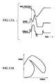
Fig. 13A is a diagram showing the feature extraction waveform data based on the actually measured data shown inFig. 12 ; -
Fig. 13B is a diagram showing the punching torque-speed characteristics based on the actually measured data shown inFig. 12 ; -
Fig. 1 is a vertical sectional view of an essential portion showing an embodiment of a servo drive system (continuous working system) of a press machine according to the present invention, andFig. 2 is a right side view thereof. The servo drive system (continuous working system) 1 of the press machine is applied to aturret punch press 10. - The
turret punch press 10 has aneccentric shaft 20 which is pivotally supported bybearings frames eccentric shaft 20 has aneccentric shaft portion 20e located substantially at a central portion between theframes ram 22 is mounted on theeccentric shaft portion 20e through a connectingrod 21. If theeccentric shaft 20 rotates or turns, theram 22 is vertically moved through the connectingrod 21 along aram guide 23, and astriker 24 mounted on a lower end of theram 22 is also vertically moved in unison with theram 22. When theram 22 moves downward, thestriker 24 pushes a punching die 26 mounted on aturret 25 to punch a work out. - The
eccentric shaft 20 is provided at its opposite ends withextensions frames Servo motors extensions main shafts 31a and 3 1 b are respectively mounted on outer sides of theframes - In the
servo motor 30a, theextension 20a of theeccentric shaft 20 is constituted as the motormain shaft 31a. That is, asleeve 33a is provided at its outer periphery with an even number (four) of magnetic pole magnets (permanent magnets) 32a in a circumferential direction at predetermined distances (90°) from one another. Thesleeve 33a is fitted around and fixed to a periphery of theextension 20a of theeccentric shaft 20 through abush 34a, thereby constituting arotor 35a. Theextension 20a of theeccentric shaft 20 serves as a center axis of therotor 35a. Theextension 20a is the motormain shaft 31a itself. Therefore, theservo motor 30a uses theextension 20a, i.e., theeccentric shaft 20 substantially as therotor 35a. - In the
servo motor 30a, anouter cylinder 36a around which three-phase armature windings Ua, Va, and Wa are wound is fitted over therotor 35a and fixed to theframe 11a, thereby constituting astator 37a. - On the other hand, in the
servo motor 30b, like theservo motor 30a, theextension 20b of theeccentric shaft 20 is constituted as the motormain shaft 31b. That is, asleeve 33b is provided at its outer periphery with an even number (four) of magnetic pole magnets (permanent magnets) 32b in a circumferential direction at predetermined distances (90°) from one another. Thesleeve 33b is fitted around and fixed to a periphery of theextension 20b of theeccentric shaft 20 through abush 34b, thereby constituting arotor 35b. Theextension 20b of theeccentric shaft 20 serves as a center axis of therotor 35b. Theextension 20b is the motormain shaft 31 b itself. Therefore, theservo motor 30b uses theextension 20b, i.e., theeccentric shaft 20 substantially as therotor 35b. - In the
servo motor 30b, anouter cylinder 36b around which three-phase armature windings Ub, Vb, and Wb are wound is fitted over therotor 35b and fixed to theframe 11b, thereby constituting astator 37b. - The
servo motor 30a and theservo motor 30b are the same, but they are symmetric with each other in a mirror image manner. Except this point, theservo motors rotors rotary encoder 38 which detects rotation angles of therotors rotary encoder 38 is commonly used. Theservo motors servo motors - That is, the magnetic pole of the
rotor 35a of theservo motor 30a (position of the magnetic pole in the circumferential direction of themagnetic pole magnet 32a) and the magnetic pole of therotor 35b of theservo motor 30b (position of the magnetic pole in the circumferential direction of themagnetic pole magnet 32b) are positioned and mounted symmetrically with each other in the mirror image manner, and the three-phase armature windings Ua, Va, and Wa of theservo motor 30a and the three-phase armature windings Ub, Vb, and Wb of theservo motor 30b are positioned and mounted symmetrically with each other in the mirror image manner in the circumferential direction. - Thus, as shown in
Fig. 3 , if apower driver 42a of aservo amplifier 40a which is a control circuit of theservo motor 30a, and apower driver 42b of aservo amplifier 40b which is a control circuit of theservo motor 30b are driven by the same gate signal, only three-phase alternating current having the same phase and same current values flows to theservo motor 30a and theservo motor 30b. Therefore, a torque vector of theservo motor 30a and a torque vector of theservo motor 30b have the same phase and thus, a composite torque of theservo motor 30a and theservo motor 30b becomes an exact sum of torques of theservo motors servo motors Figs. 1 and3 or theservo motors - As shown in
Fig. 3 , theservo amplifier 40a includes aconverter 41 a which A-D converts three-phase commercial alternating power supply, apower driver 42a, areactor 43a which is provided on a front stage of thepower driver 42a and which suppresses peak current by cutting off high frequency current component, and acapacitor 44a for storage having a large capacity. Six power transistors Q of thepower driver 42a are driven by a gate signal so that theservo amplifier 40a drives theservo motor 30a by three-phase alternating output of thepower driver 42a. Diodes D for flowing regenerative current generated during speed reducing period of theservo motor 30a are connected to the power transistors Q of thepower driver 42a. The regenerative current flows into thecapacitor 44a and is accumulated as regenerative electricity. Thecapacitor 44a supplies electric energy which runs short due to suppression of the peak current by thereactor 43a using the regenerative electricity, i.e., thecapacitor 44a supplies high speed operation electric energy and/or punching out electric energy. Theservo amplifier 40b has the same structure as that of theservo amplifier 40a. - By such control of the
servo amplifiers servo motors eccentric shaft 20 through an angle range θ corresponding to a space between positions L and H so that theeccentric shaft portion 20e of theeccentric shaft 20 vertically moves between the L position corresponding to a case where theram 22 is in a predetermined lower end position required for punching working (seeFigs. 4A to 4C ) and the H position corresponding to a case where theram 22 is returned from the L position and is in an upper end position where thestriker 24 at a lower end of theram 22 is separated from an upper surface of the punching die 26. With this, a work is punched. - As shown in
Fig. 4A , the L position of theeccentric shaft portion 20e of theeccentric shaft 20 corresponding to the lower end position of theram 22 is set to a position slightly short of and above a bottom dead center B of the entire vertically possible stroke of theram 22 determined by an eccentric amount E (distance between an axis of theeccentric shaft 20 and an axis of theeccentric shaft portion 20e) of theeccentric shaft 20. Further, the H position of theeccentric shaft portion 20e of theeccentric shaft 20 corresponding to the upper end position of theram 22 is set to a position slightly below a medium height M of the entire vertically possible stroke of theram 22. That is, although the reciprocating turning angle range θ of theeccentric shaft 20 depends on the stroke of the punching die 26 to be used, the angle range θ is set to about 40° to 60°. - As shown in
Fig. 4B , in theservo motors eccentric shaft portion 20e (i.e., ram 22) of theeccentric shaft 20 is positioned on a top dead center T when the die is to be exchanged or the turret is to be rotated. When the working is started, theservo motors eccentric shaft portion 20e of theeccentric shaft 20 to the L position corresponding to the lower end position of theram 22 from the top dead center T, thereby lowering theram 22, and after a first punching working is carried out, theeccentric shaft portion 20e is returned to the H position corresponding to the upper end position of theram 22 where theram 22 stands-by. In a second or subsequent punching working, theeccentric shaft portion 20e of theeccentric shaft 20 is turned such as to reciprocate through the reciprocating turning angle range θ between the H position and the L position. - Among the entire rotating range of the
eccentric shaft portion 20e of theeccentric shaft 20, if a half circumferential range is always used as shown inFig. 4B , there is an adverse possibility that inconvenience is generated because lubricant oil is not delivered uniformly and various portions are not equally used. To avoid such inconvenience, theservo motors Fig. 4C . It is preferable that the side shown inFig. 4B and the side shown inFig. 4C are switched whenever the die is to be exchanged or the turret is to be rotated, or automatically according to a predetermined number of punching operations. - According to the
turret punch press 10 of the present embodiment, the pair ofservo motors frames eccentric shaft 20. That is, for example, theservo motors frame 11a or theframe 11b. In this case, since a stress caused by the weight of the servo motor (30) is received only by oneframe frames bearings turret punch press 10, however, there is a merit that such stress distortion is not generated, and the heat can be dispersed and equalized. Therefore, stable operation can be realized. - As explained above, the
servo motors eccentric shaft 20, and theeccentric shaft 20 continuously reciprocates and turns only in the reciprocating turning angle range θ between the L position corresponding to the lower end position of theram 22 and the H position corresponding to the upper end position of theram 22. This operation is extremely effective for speeding up theram 22 when a work is subjected to continuous punching working. - The operation of the present embodiment will be explained next with reference to explanatory views shown in
Figs. 5 to 13B . -
Fig. 5 shows examples 1) and 2) of speed-torque characteristics of theservo motors Fig. 5 shows the upper limit speed at which theservo motors ram 22 required for a load applied to theram 22 is to be generated. - As can be seen from
Fig. 5 , with theservo motors ram 22 is light, since the required torque is small, the driving speed of theram 22 is not reduced and the punching speed of the punching is fast. On the other hand, as the load applied to theram 22 is heavier, the required torque becomes greater, the driving speed of theram 22 is reduced, and the punching speed of punching becomes slower. Reasons of generation of noise by punching working are varied depending upon various conditions such as the material of the work, the plate thickness, and the like. However, it is known that the noise is large when the punching speed by driving of a ram is fast, the noise becomes smaller when the punching speed becomes slower, and when the punching speed is constant, the noise is small when the load is light, and as the load becomes heavier, the noise becomes larger. From this fact, like the speed-torque characteristics of theservo motors Fig. 5 , as the load is heavier, the ram speed becomes slower, and this reduces the noise. Further, it is apparent, from the following actually measured data of punching working of various works and feature extraction waveform data based thereon, that such reduction in ram speed does not deteriorate the operation efficiency. -
Fig. 6 shows the actually measured data of a punching working when there is no work,Fig. 7A shows the feature extraction waveform data based on the actually measured data, andFig. 7B shows the punching torque-speed characteristics based on the actually measured data. - As shown in
Figs. 6 ,7A, and 7B , when there is no work, in a first half of one cycle of theram 22, a speed curve and a torque curve rise in a normal rotation direction to keep constant values. With this, a ram position curve is substantially uniformly lowered from the upper end position (corresponding to H position) to the lower end position (corresponding to L position). Next, in a second half of the one cycle of theram 22, the speed curve and the torque curve rise in the reverse rotation direction to keep the constant values. With this, the ram position curve is substantially uniformly moved upward from the lower end position (corresponding to L position) to the upper end position (corresponding to H position). -
Fig. 8 shows the actually measured data of a punching working when a thin plate work is punched out using a punch having a small diameter,Fig. 9A shows the feature extraction waveform data based on the actually measured data, andFig. 9B shows the punching torque-speed characteristics based on the actually measured data. - As shown in
Figs. 8 to 9B , when the thin plate work is punched out using the punch having the small diameter, the behavior in the first half of one cycle of theram 22 is different from that in the case shown inFigs. 6 to 7B . That is, in the initial operation, like the case shown inFigs. 6 to 7B , the speed curve and the torque curve rise in the normal rotation direction to the constant values. With this, the ram position curve starts lowering substantially uniformly from the upper end position (corresponding to H position). However, if thestriker 24 of the lower end of theram 22 pushes the punching die 26 and a tip end of the punching die 26 abuts against an upper surface of the work and thestriker 24 receives a load from the work, the torque curve abruptly rises and the speed curve is reduced and with this, the lowering motion of the ram position curve becomes moderate (slow). If the tip end of the punching die 26 lowers to a position short of a lower surface of the work and the load received from the work is abruptly reduced, the torque curve abruptly lowers, the speed curve is accelerated beyond the constant value to restore the speed reduction and with this, the lowering speed of the ram position curve is also accelerated. Thereafter, in the second half of one cycle of theram 22, like the case shown inFigs. 6 to 7B , the ram position curve substantially uniformly rises from the lower end position (corresponding to L position) to the upper end position (corresponding to H position). -
Fig. 10 shows the actually measured data of a punching working when a thin plate work is punched out using a punch having a large diameter,Fig. 11A shows the feature extraction waveform data based on the actually measured data, andFig. 11B shows the punching torque-speed characteristics based on the actually measured data. - As shown in
Figs. 10 to 11B , when a thin plate work is punched out using a punch having a large diameter, the behavior in the first half of one cycle of theram 22 is different from that in the case shown inFigs. 8 to 9B . That is, in the initial operation, like the case shown inFigs. 8 to 9B , the speed curve and the torque curve rise in the normal rotation direction to the constant values. With this, the ram position curve starts lowering substantially uniformly from the upper end position (corresponding to H position). However, if thestriker 24 of the lower end of theram 22 pushes the punching die 26 and load from the work is received, since the diameter of the punch is larger than that shown inFigs. 8 to 9B , a load received from the work is great and thus, the torque curve rises largely as compared with the case shown inFigs. 8 to 9B , and the speed curve reduces largely as compared with the case shown inFigs. 8 to 9B . With this, the lowering motion of the ram position curve becomes much more moderate (slower) than that shown inFigs. 8 to 9B . If the tip end of the punching die 26 lowers to a position short of the lower surface of the work and the load received from the work is abruptly reduced, the torque curve abruptly lowers, the speed curve is accelerated larger than that shown inFigs. 8 to 9B so as to restore the speed reduction and with this, the lowering speed of the ram position curve is also accelerated larger than that shown inFigs. 8 to 9B . Thereafter, in the second half of one cycle of theram 22, like the case shown inFigs. 8 to 9B , the ram position curve substantially uniformly rises from the lower end position (corresponding to L position) to the upper end position (corresponding to H position). -
Fig. 12 shows the actually measured data of a punching working when a thick plate work is punched out using a punch having a small diameter,Fig. 13A shows the feature extraction waveform data based on the actually measured data, andFig. 13B shows the punching torque-speed characteristics based on the actually measured data. - As shown in
Figs. 12 to 13B , when a thick plate work is punched out using a punch having a small diameter, since the plate of the work is thicker as compared with the case shown inFigs. 8 to 9B , a load received from the work is greater. Therefore, the behavior in the first half of one cycle of theram 22 is different from that of the case shown inFigs. 8 and9 , but the difference is not great as compared with the case shown inFigs. 10 to 11B . - If the speed curve is reduced depending upon the magnitude of the load applied to the
ram 22 and the lowering motion of the ram position curve becomes moderate (slow), the speed curve is accelerated beyond the constant value to restore the speed reduction, and the lowering speed of the ram position curve is also accelerated, and the reduction in ram speed caused by the load is absorbed and overcome as acceleration and deceleration in one cycle of theram 22. Therefore, time required through one cycle of theram 22 is substantially the same, and this does not hinder the speed up of theram 22. - Such speed-torque characteristics of the motor can be explained as follows. The motor converts the supplied electric energy into energy applied to a load. With the
servo motors servo amplifiers - On the other hand, with the
servo motors ram 22 and the reverse rotation of the appropriate acceleration which moves theram 22 upward are repeated. Therefore, the motor torque can be divided into a torque for generating kinetic energy of theram 22 and a torque for generating the punching pressurizing force. - In such a case, if the acceleration is very slow (if the vertical movement of the
ram 22 is delayed), a small amount of kinetic energy generating torque suffices and thus, almost all of the motor torque can be utilized as the pressurizing force generating torque. Therefore, even if a great pressurizing force is required depending upon the conditions such as the plate thickness and material of the work, sufficient pressurizing force can be generated, and the kinetic energy generating torque does not come short and the speed of theram 22 is not affected. - In actual practice, since high acceleration to some extent (fast vertical movement of the ram 22) is required for the operation efficiency, the amount of pressurizing force generating torque of the motor torque is limited. Therefore, if a great pressurizing force is required depending upon the conditions such as the plate thickness and material of the work, most of the motor torque is used for generating the pressurizing force, the kinetic energy generating torque comes short, the speed of the
ram 22 can not be maintained, and the lowering speed of theram 22 is reduced. - However, the deceleration of the lowering speed of the
ram 22 is the characteristic which is extremely effective for reducing a noise caused by the punching operation of punching, a noise caused by vibration, and vibration itself. That is, when the required pressurizing force (the number of pressure tons) is relatively small depending upon the conditions such as the plate thickness and material of the work, since the speed reduction of the lowering speed of theram 22 is small, the punching action with light load becomes relatively fast. When the required pressurizing force (the number of pressure tons) is relatively large, since the speed reduction of the lowering speed of theram 22 is large, the punching action with heavy load becomes relatively slow. The variation in punching speed is automatically determined according to the required pressurizing force (the number of pressure tons). Thus, a command of punching pattern (lowering pattern of the ram 22) by the number of punching tons is not necessary. That is, it becomes impossible to maintain the lowering speed of theram 22 and with this, optimal punching pattern (lowering pattern of the ram 22) is automatically produced. - Conversely, the speed-torque characteristics of the
servo motors servo motors servo amplifiers turret punch press 10. With this, a noise caused by the punching action of punching, a noise caused by vibration, and the vibration itself can be reduced. - In an electric punch press in which a mechanism such as a toggle and a flywheel is not used and a motor and a ram operation shaft are directly connected to each other, it can be said that the punch press that can reduce a noise caused by the punching action of punching, a noise caused by vibration, and the vibration itself based on the explanation with reference to
Figs. 5 to 13B has the same speed-torque characteristics as those of theservo motors - The operation of the
reactors capacitors servo amplifiers - If a value of each of the
reactors reactors servo amplifiers reactors - However, in the case of the punching working using a punch press, in order to move, at high speed, the
eccentric shaft 20 which vertically moves theram 22, large kinetic energy is required, and its frequency is also high. Thus, if the L values of thereactors servo amplifiers servo motors reactors servo amplifiers servo motors - To complement the supply of the high speed operation electric energy and/or the supply of the punching operation electric energy from the
servo amplifiers servo motors capacitors capacitors servo amplifiers servo motors - Therefore, if the
reactors capacitors turret punch press 10. - Although both the
servo motors servo motors servo motors ram 22 becomes moderate and the noise is reduced, and power may be saved. However, it is preferable to take necessary measures against heat such as cooling.
Claims (5)
- A press machine with a servo drive system comprising:a ram (22),an operation shaft which vertically moves the ram (22), the operation shaft comprises an eccentric shaft (20),a pair of servo motors (30a,30b) which operate as power sources of the ram (22) and which composite and use torques based on the same speed-torque characteristics, thereby generating ram pressure,the pair of servo motors (30a,30b) are opposed to each other at opposite ends (20a,20b) of the eccentric shaft (20) formed as motor main shafts (31 a,31 b), andthe pair of servo motors (30a,30b) are operated so that the pair of servo motors (30a, 30b) directly drive the eccentric shaft (20) to vertically move the ram (22), characterised in that the pair of servo motors (30a,30b) are formed symmetrically with each other in a mirror image manner, each of said servo motors (30a,30b) comprises a sleeve (33a,33b) provided at its outer periphery with an even number of magnetic pole magnets (32a,32b) along a circumferential direction thereof at predetermined distances from one another are fitted over peripheries of the end (20a,20b) of the eccentric shaft (20), thereby forming a rotor (35a,35b) of the servo motor (30a,30b),magnetic pole positions of the sleeve (33a,33b) are positioned such that the sleeves (33a,33b) of the pair of are servo motors (30a,30b) symmetric with each other in a mirror image manner and the sleeves (33a,33b) are fixed by bushes (34a, 34b),a stator (37a,37b) each of said servo motors (30a,30b) comprises an outer cylinder (36a,36b) around which three-phase armature windings (Ua,Va,Wa) are wound, and the outer cylinder is (36a,36b) respectively fitted over the rotor (35a,35b), andthe outer cylinders (36a,36b) of the pair of are servo motors (30a,30b) are positioned such that positions of the three-phase armature windings (Ua,Va,Wa) of the outer cylinders (36a,36b) in the circumferential direction are symmetric with each other in a mirror image manner, and the outer cylinders (36a,36b) are fixed to left and right supporting frames (11a, 11b) of the eccentric shaft (20).
- A press machine according to claim 1, wherein a power unit of a servo amplifier (40a) of one of the pair of servo motors (30a) and a power unit of a servo amplifier (40b) of the other of the pair of servo motors (30b) are driven by the same gate signal, thereby integrally operating both the servo motors (30a,30b).
- A servo drive system according to claim 1 or 2, wherein the operation shaft (20) is continuously reciprocated and turned through an angle range corresponding to a distance between a lower end position required for press working by the ram (22) and a position where the ram (22) is returned from the lower end position and a lower end of the ram (22) is separated from a tool upper surface such that the ram (22) vertically moves between these positions by the pair of servo motors (30a,30b), thereby subjecting a work to a continuous press working.
- A servo drive system according to one of the claims 1 to 3, wherein each servo motor (30a,30b) has a control power driver (42a,42b), the power driver being provided at its front stage with a reactor (43a,43b) which is adapted to suppress peak current by cutting off high frequency current component, and a capacitor (44a,44b) which is adapted to supply electric energy which becomes short due to suppression of the peak current.
- A servo drive system according to claim 4, wherein the capacitor (44a,44b) is adapted to supply high speed operation electric energy and/or punching out electric energy which become short due to suppression of the peak current.
Priority Applications (4)
| Application Number | Priority Date | Filing Date | Title |
|---|---|---|---|
| EP10009357.4A EP2261017B1 (en) | 2002-06-18 | 2003-06-17 | Servo drive system and continuous working system of press machine |
| EP10009359.0A EP2261019B1 (en) | 2002-06-18 | 2003-06-17 | Servo drive system and continuous working system of press machine |
| EP10009360.8A EP2261020B1 (en) | 2002-06-18 | 2003-06-17 | Servo drive system and continuous working system of press machine |
| EP10009358.2A EP2261018B1 (en) | 2002-06-18 | 2003-06-17 | Method of regulating a servo drive system and servo drive system of a press machine |
Applications Claiming Priority (15)
| Application Number | Priority Date | Filing Date | Title |
|---|---|---|---|
| JP2002177145 | 2002-06-18 | ||
| JP2002177143 | 2002-06-18 | ||
| JP2002177149 | 2002-06-18 | ||
| JP2002177150 | 2002-06-18 | ||
| JP2002177143 | 2002-06-18 | ||
| JP2002177145A JP3790188B2 (en) | 2002-06-18 | 2002-06-18 | Servo drive system for punch press |
| JP2002177149 | 2002-06-18 | ||
| JP2002177150 | 2002-06-18 | ||
| JP2003145374A JP3790231B2 (en) | 2002-06-18 | 2003-05-22 | Servo drive system for press machine |
| JP2003145372 | 2003-05-22 | ||
| JP2003145374 | 2003-05-22 | ||
| JP2003145377A JP3802513B2 (en) | 2002-06-18 | 2003-05-22 | Press machine continuous processing system |
| JP2003145372A JP3790230B2 (en) | 2002-06-18 | 2003-05-22 | Servo drive system for press machine |
| JP2003145377 | 2003-05-22 | ||
| PCT/JP2003/007675 WO2003106154A1 (en) | 2002-06-18 | 2003-06-17 | Servo-drive system and continuous finishing system of press |
Related Child Applications (8)
| Application Number | Title | Priority Date | Filing Date |
|---|---|---|---|
| EP10009357.4A Division EP2261017B1 (en) | 2002-06-18 | 2003-06-17 | Servo drive system and continuous working system of press machine |
| EP10009358.2A Division EP2261018B1 (en) | 2002-06-18 | 2003-06-17 | Method of regulating a servo drive system and servo drive system of a press machine |
| EP10009359.0A Division EP2261019B1 (en) | 2002-06-18 | 2003-06-17 | Servo drive system and continuous working system of press machine |
| EP10009360.8A Division EP2261020B1 (en) | 2002-06-18 | 2003-06-17 | Servo drive system and continuous working system of press machine |
| EP10009360.8 Division-Into | 2010-09-08 | ||
| EP10009359.0 Division-Into | 2010-09-08 | ||
| EP10009358.2 Division-Into | 2010-09-08 | ||
| EP10009357.4 Division-Into | 2010-09-08 |
Publications (3)
| Publication Number | Publication Date |
|---|---|
| EP1541330A1 EP1541330A1 (en) | 2005-06-15 |
| EP1541330A4 EP1541330A4 (en) | 2007-03-14 |
| EP1541330B1 true EP1541330B1 (en) | 2010-11-03 |
Family
ID=29741210
Family Applications (5)
| Application Number | Title | Priority Date | Filing Date |
|---|---|---|---|
| EP10009360.8A Expired - Lifetime EP2261020B1 (en) | 2002-06-18 | 2003-06-17 | Servo drive system and continuous working system of press machine |
| EP03760155A Expired - Lifetime EP1541330B1 (en) | 2002-06-18 | 2003-06-17 | Press machine with a servo-drive system |
| EP10009357.4A Expired - Lifetime EP2261017B1 (en) | 2002-06-18 | 2003-06-17 | Servo drive system and continuous working system of press machine |
| EP10009358.2A Expired - Lifetime EP2261018B1 (en) | 2002-06-18 | 2003-06-17 | Method of regulating a servo drive system and servo drive system of a press machine |
| EP10009359.0A Expired - Lifetime EP2261019B1 (en) | 2002-06-18 | 2003-06-17 | Servo drive system and continuous working system of press machine |
Family Applications Before (1)
| Application Number | Title | Priority Date | Filing Date |
|---|---|---|---|
| EP10009360.8A Expired - Lifetime EP2261020B1 (en) | 2002-06-18 | 2003-06-17 | Servo drive system and continuous working system of press machine |
Family Applications After (3)
| Application Number | Title | Priority Date | Filing Date |
|---|---|---|---|
| EP10009357.4A Expired - Lifetime EP2261017B1 (en) | 2002-06-18 | 2003-06-17 | Servo drive system and continuous working system of press machine |
| EP10009358.2A Expired - Lifetime EP2261018B1 (en) | 2002-06-18 | 2003-06-17 | Method of regulating a servo drive system and servo drive system of a press machine |
| EP10009359.0A Expired - Lifetime EP2261019B1 (en) | 2002-06-18 | 2003-06-17 | Servo drive system and continuous working system of press machine |
Country Status (8)
| Country | Link |
|---|---|
| US (3) | US7475584B2 (en) |
| EP (5) | EP2261020B1 (en) |
| KR (2) | KR100769203B1 (en) |
| CN (3) | CN101637979B (en) |
| AT (1) | ATE486713T1 (en) |
| DE (1) | DE60334816D1 (en) |
| TW (1) | TW589250B (en) |
| WO (1) | WO2003106154A1 (en) |
Cited By (1)
| Publication number | Priority date | Publication date | Assignee | Title |
|---|---|---|---|---|
| CN102712157A (en) * | 2009-11-04 | 2012-10-03 | 迪芬巴赫机械工程有限公司 | Press with a directly driven crank drive |
Families Citing this family (32)
| Publication number | Priority date | Publication date | Assignee | Title |
|---|---|---|---|---|
| CN101637979B (en) * | 2002-06-18 | 2012-07-04 | 株式会社阿玛达 | Servo-drive system and continuous processing system for press machine |
| US7516226B2 (en) * | 2004-09-30 | 2009-04-07 | Agere Systems Inc. | Transmit adaptive equalization using ordered sets |
| DE102005040428B3 (en) * | 2005-08-26 | 2007-04-19 | Ortlinghaus-Werke Gmbh | Drive for a press |
| DE102006015581B3 (en) * | 2006-04-04 | 2007-10-04 | Aradex Ag | Deformation process implementing method, involves determining temporal sequences of motor current as measure for force or torque of direct drive by integrating measuring device in direct drive |
| NL2000449C2 (en) * | 2007-01-22 | 2008-07-23 | Fico Bv | Method and device for mechanically processing semiconductor products in a press. |
| KR100870055B1 (en) | 2007-02-07 | 2008-11-24 | 주식회사 모비코 | Electric press |
| DE102008028652B3 (en) * | 2008-06-18 | 2010-01-14 | Schuler Pressen Gmbh & Co. Kg | Press Direct Drive |
| EP2166662B1 (en) * | 2008-09-18 | 2011-04-06 | Siemens Aktiengesellschaft | Machine with buffer drive without centrifugal mass |
| DE102008064229A1 (en) * | 2008-12-22 | 2010-07-01 | Müller Weingarten AG | Method for controlling a forging press |
| CN101480851B (en) * | 2009-01-24 | 2011-12-14 | 宁波精达成形装备股份有限公司 | Press |
| DE102009029921B4 (en) * | 2009-06-23 | 2012-06-06 | Schuler Pressen Gmbh & Co. Kg | Eccentric direct drive |
| JP4712884B2 (en) * | 2009-07-07 | 2011-06-29 | ファナック株式会社 | Press machine control device |
| DE102009035215A1 (en) * | 2009-07-29 | 2011-02-10 | Dieffenbacher Gmbh + Co. Kg | Press with a directly driven crank mechanism |
| DE102009035214A1 (en) * | 2009-07-29 | 2011-02-24 | Dieffenbacher Gmbh + Co. Kg | Press with a directly driven crank mechanism |
| CN101697436B (en) * | 2009-10-27 | 2011-09-21 | 江苏金方圆数控机床有限公司 | Main transmission structure of actuating motor in punching machinery |
| DE102009051939A1 (en) * | 2009-11-04 | 2011-05-05 | Dieffenbacher Gmbh + Co. Kg | Press with a directly driven crank mechanism, press line of such presses and a method for producing a press with at least one direct drive. |
| JP5649502B2 (en) * | 2010-05-25 | 2015-01-07 | アイダエンジニアリング株式会社 | Multi-point servo press |
| JP5205417B2 (en) * | 2010-05-27 | 2013-06-05 | コマツ産機株式会社 | Press machine and control method of press machine |
| JP5301500B2 (en) * | 2010-05-28 | 2013-09-25 | アイダエンジニアリング株式会社 | Servo press machine driven by multiple motors |
| CN102025234B (en) * | 2010-12-10 | 2012-08-22 | 上海电气集团上海电机厂有限公司 | Method for turning rotor core punching piece |
| DE102011001314C5 (en) * | 2011-03-16 | 2016-03-03 | Schuler Pressen Gmbh | Drawing press with two lockable rams |
| EP2554363B1 (en) * | 2011-08-02 | 2016-09-28 | Siemens Aktiengesellschaft | Electric drive for a press |
| CN102320155A (en) * | 2011-09-30 | 2012-01-18 | 江苏扬力数控机床有限公司 | Double servo motor direct-driven numerical control turret punch press |
| US9701084B2 (en) | 2013-03-12 | 2017-07-11 | Vamco International, Inc. | Press machine |
| CN103419246A (en) * | 2013-08-14 | 2013-12-04 | 吴江市晴亿纺织有限公司 | Manual perforating machine |
| DE102014115240B4 (en) | 2014-10-20 | 2017-08-24 | Schuler Pressen Gmbh | Press drive device for a press and press with press drive device |
| DE102014115238B4 (en) * | 2014-10-20 | 2017-02-02 | Schuler Pressen Gmbh | Press drive device for a press and press with press drive device |
| CN104626639A (en) * | 2015-02-12 | 2015-05-20 | 江苏扬力数控机床有限公司 | Integrated servo main transmission mechanism for CNC (computer numerical control) turret punch press |
| CN104608415B (en) * | 2015-02-12 | 2016-03-09 | 江苏扬力数控机床有限公司 | A kind of open-core type servo main transmission mechanism being applied to NC turret punch machine |
| JP6666077B2 (en) * | 2015-04-30 | 2020-03-13 | コマツ産機株式会社 | Press system and control method of press system |
| PL422234A1 (en) * | 2017-07-17 | 2019-01-28 | Przedsiębiorstwo Concept Stal B&S Lejman Spółka Jawna | Press with servomechanical drive |
| CN110165830A (en) * | 2018-04-13 | 2019-08-23 | 上海弋朋自动化科技有限公司 | A kind of NC turret punch machine double speed or double winding formed punch servo motor mechanism |
Family Cites Families (33)
| Publication number | Priority date | Publication date | Assignee | Title |
|---|---|---|---|---|
| US2771790A (en) * | 1954-07-12 | 1956-11-27 | Niagara Machine & Tool Works | Double drive power punch press |
| JPS54105716A (en) * | 1978-02-08 | 1979-08-20 | Hitachi Ltd | Controller for thyristor motor |
| IT1224044B (en) | 1988-12-29 | 1990-09-26 | Prima Ind Spa | PRECISION BENDING PRESS FOR LONG SHEET PIECES |
| US6831166B2 (en) | 1992-10-23 | 2004-12-14 | Isis Pharmaceuticals, Inc. | Derivatized oligonucleotides having improved uptake and other properties |
| DE69301361T2 (en) * | 1992-03-16 | 1996-09-05 | Ishikawajima Harima Heavy Ind | Drive device for a mechanical press |
| JPH0755398B2 (en) * | 1992-04-28 | 1995-06-14 | 株式会社栗本鐵工所 | Slide adjustment device for forging press |
| US6759201B2 (en) | 2000-10-25 | 2004-07-06 | The General Hospital Corporation | Method of identifying a neural progenitor cell by evaluating expression of daedalos |
| JPH0847279A (en) * | 1994-08-01 | 1996-02-16 | Toshiba Corp | Power supply regeneration circuit |
| JP2785719B2 (en) * | 1994-10-07 | 1998-08-13 | 村田機械株式会社 | Control device for toggle type punch press |
| JP3483010B2 (en) * | 1994-11-29 | 2004-01-06 | アピックヤマダ株式会社 | Motor press mechanism |
| US5669257A (en) | 1994-12-28 | 1997-09-23 | Yazaki Corporation | Method of crimping terminal and apparatus for the same |
| JP3783063B2 (en) * | 1995-02-17 | 2006-06-07 | 玉川マシナリー株式会社 | Powder molding press, upper punch control method of powder molding press, and upper punch control device of powder molding press |
| JP3850934B2 (en) | 1995-12-15 | 2006-11-29 | アマダ・エムエフジー・アメリカ・インコーポレイティド | Ram lifting drive device and press machine |
| JP3171124B2 (en) * | 1996-09-05 | 2001-05-28 | 村田機械株式会社 | Punch press drive |
| US5952755A (en) | 1997-03-18 | 1999-09-14 | Electric Boat Corporation | Permanent magnet motor rotor |
| JPH10328891A (en) | 1997-05-30 | 1998-12-15 | Amada Eng Center:Kk | Press |
| DE19810406A1 (en) * | 1998-03-11 | 1999-09-16 | Schuler Pressen Gmbh & Co | Eccentric press with variable slide movement |
| JP4109775B2 (en) | 1998-12-21 | 2008-07-02 | 株式会社アマダエンジニアリングセンター | Press machine |
| JP2000288792A (en) * | 1999-04-06 | 2000-10-17 | Amada Co Ltd | Press working machine |
| JP2000358382A (en) * | 1999-06-14 | 2000-12-26 | Nikki Denso Kk | Device for driving three-phase motor |
| JP3227440B2 (en) * | 1999-08-05 | 2001-11-12 | 株式会社放電精密加工研究所 | Pressurizing device |
| JP2001062596A (en) * | 1999-08-24 | 2001-03-13 | Ns Engineering:Kk | Press machine assembling method and press machine |
| JP2001062591A (en) | 1999-08-24 | 2001-03-13 | Amada Co Ltd | Press machine |
| JP3818823B2 (en) * | 2000-03-29 | 2006-09-06 | シャープ株式会社 | Inverter washing machine |
| JP3533372B2 (en) | 2000-12-19 | 2004-05-31 | 象印マホービン株式会社 | Electric cooker |
| JP2002210600A (en) * | 2001-01-18 | 2002-07-30 | Yamada Dobby Co Ltd | Controller for servo press |
| US7219016B2 (en) | 2001-04-20 | 2007-05-15 | Yale University | Systems and methods for automated analysis of cells and tissues |
| CA2364166A1 (en) | 2001-11-28 | 2003-05-28 | Brenda Schultz | Padded knee and elbow rest |
| US6658677B2 (en) | 2002-02-01 | 2003-12-09 | P. J. Kids, Llc | System for replacing decorative furniture panels |
| DE10204248B4 (en) | 2002-02-02 | 2006-02-02 | Airbus Deutschland Gmbh | Filter device for a vacuum toilet system |
| CN101637979B (en) * | 2002-06-18 | 2012-07-04 | 株式会社阿玛达 | Servo-drive system and continuous processing system for press machine |
| JP4318074B2 (en) * | 2003-08-08 | 2009-08-19 | 村田機械株式会社 | Punch press |
| DE102004009256B4 (en) * | 2004-02-26 | 2008-04-03 | Schuler Pressen Gmbh & Co. Kg | Mechanical multi-servo press |
-
2003
- 2003-06-17 CN CN2009101514514A patent/CN101637979B/en not_active Expired - Fee Related
- 2003-06-17 US US10/517,317 patent/US7475584B2/en active Active
- 2003-06-17 TW TW92116340A patent/TW589250B/en not_active IP Right Cessation
- 2003-06-17 EP EP10009360.8A patent/EP2261020B1/en not_active Expired - Lifetime
- 2003-06-17 KR KR1020047020648A patent/KR100769203B1/en active IP Right Grant
- 2003-06-17 EP EP03760155A patent/EP1541330B1/en not_active Expired - Lifetime
- 2003-06-17 EP EP10009357.4A patent/EP2261017B1/en not_active Expired - Lifetime
- 2003-06-17 WO PCT/JP2003/007675 patent/WO2003106154A1/en active Application Filing
- 2003-06-17 AT AT03760155T patent/ATE486713T1/en not_active IP Right Cessation
- 2003-06-17 CN CNB038139898A patent/CN100532081C/en not_active Expired - Fee Related
- 2003-06-17 CN CN201210015513.0A patent/CN102582099B/en not_active Expired - Fee Related
- 2003-06-17 DE DE60334816T patent/DE60334816D1/en not_active Expired - Lifetime
- 2003-06-17 EP EP10009358.2A patent/EP2261018B1/en not_active Expired - Lifetime
- 2003-06-17 KR KR1020077013395A patent/KR100857503B1/en active IP Right Grant
- 2003-06-17 EP EP10009359.0A patent/EP2261019B1/en not_active Expired - Lifetime
-
2008
- 2008-11-14 US US12/271,368 patent/US7637139B2/en not_active Expired - Lifetime
- 2008-11-14 US US12/271,439 patent/US7640778B2/en not_active Expired - Fee Related
Cited By (1)
| Publication number | Priority date | Publication date | Assignee | Title |
|---|---|---|---|---|
| CN102712157A (en) * | 2009-11-04 | 2012-10-03 | 迪芬巴赫机械工程有限公司 | Press with a directly driven crank drive |
Also Published As
Similar Documents
| Publication | Publication Date | Title |
|---|---|---|
| EP1541330B1 (en) | Press machine with a servo-drive system | |
| US7752880B2 (en) | Linear motor mounted press machine and method for controlling linear motor mounted press machine | |
| EP1892083A2 (en) | Linear motor mounted press machine and method for controlling linear motor mounted press machine | |
| JP4381386B2 (en) | Servo drive system for press machine | |
| JP3802513B2 (en) | Press machine continuous processing system | |
| JP4381387B2 (en) | Servo drive system for press machine | |
| JP3790188B2 (en) | Servo drive system for punch press | |
| JP3790230B2 (en) | Servo drive system for press machine | |
| JP3790231B2 (en) | Servo drive system for press machine | |
| JP2005205485A (en) | Continuously working system for press | |
| JP4355520B2 (en) | Servo drive system for punch press | |
| CN102555272B (en) | Servo drive system in press and Continuous maching system |
Legal Events
| Date | Code | Title | Description |
|---|---|---|---|
| PUAI | Public reference made under article 153(3) epc to a published international application that has entered the european phase |
Free format text: ORIGINAL CODE: 0009012 |
|
| 17P | Request for examination filed |
Effective date: 20050118 |
|
| AK | Designated contracting states |
Kind code of ref document: A1 Designated state(s): AT BE BG CH CY CZ DE DK EE ES FI FR GB GR HU IE IT LI LU MC NL PT RO SE SI SK TR |
|
| AX | Request for extension of the european patent |
Extension state: AL LT LV MK |
|
| DAX | Request for extension of the european patent (deleted) | ||
| A4 | Supplementary search report drawn up and despatched |
Effective date: 20070214 |
|
| 17Q | First examination report despatched |
Effective date: 20071012 |
|
| RAP1 | Party data changed (applicant data changed or rights of an application transferred) |
Owner name: AMADA COMPANY, LTD. |
|
| GRAP | Despatch of communication of intention to grant a patent |
Free format text: ORIGINAL CODE: EPIDOSNIGR1 |
|
| RTI1 | Title (correction) |
Free format text: PRESS MACHINE WITH A SERVO-DRIVE SYSTEM |
|
| GRAS | Grant fee paid |
Free format text: ORIGINAL CODE: EPIDOSNIGR3 |
|
| GRAA | (expected) grant |
Free format text: ORIGINAL CODE: 0009210 |
|
| AK | Designated contracting states |
Kind code of ref document: B1 Designated state(s): AT BE BG CH CY CZ DE DK EE ES FI FR GB GR HU IE IT LI LU MC NL PT RO SE SI SK TR |
|
| REG | Reference to a national code |
Ref country code: GB Ref legal event code: FG4D |
|
| REG | Reference to a national code |
Ref country code: CH Ref legal event code: EP |
|
| REG | Reference to a national code |
Ref country code: IE Ref legal event code: FG4D |
|
| REF | Corresponds to: |
Ref document number: 60334816 Country of ref document: DE Date of ref document: 20101216 Kind code of ref document: P |
|
| REG | Reference to a national code |
Ref country code: NL Ref legal event code: VDEP Effective date: 20101103 |
|
| PG25 | Lapsed in a contracting state [announced via postgrant information from national office to epo] |
Ref country code: NL Free format text: LAPSE BECAUSE OF FAILURE TO SUBMIT A TRANSLATION OF THE DESCRIPTION OR TO PAY THE FEE WITHIN THE PRESCRIBED TIME-LIMIT Effective date: 20101103 Ref country code: SE Free format text: LAPSE BECAUSE OF FAILURE TO SUBMIT A TRANSLATION OF THE DESCRIPTION OR TO PAY THE FEE WITHIN THE PRESCRIBED TIME-LIMIT Effective date: 20101103 Ref country code: FI Free format text: LAPSE BECAUSE OF FAILURE TO SUBMIT A TRANSLATION OF THE DESCRIPTION OR TO PAY THE FEE WITHIN THE PRESCRIBED TIME-LIMIT Effective date: 20101103 Ref country code: PT Free format text: LAPSE BECAUSE OF FAILURE TO SUBMIT A TRANSLATION OF THE DESCRIPTION OR TO PAY THE FEE WITHIN THE PRESCRIBED TIME-LIMIT Effective date: 20110303 Ref country code: AT Free format text: LAPSE BECAUSE OF FAILURE TO SUBMIT A TRANSLATION OF THE DESCRIPTION OR TO PAY THE FEE WITHIN THE PRESCRIBED TIME-LIMIT Effective date: 20101103 Ref country code: BG Free format text: LAPSE BECAUSE OF FAILURE TO SUBMIT A TRANSLATION OF THE DESCRIPTION OR TO PAY THE FEE WITHIN THE PRESCRIBED TIME-LIMIT Effective date: 20110203 Ref country code: SI Free format text: LAPSE BECAUSE OF FAILURE TO SUBMIT A TRANSLATION OF THE DESCRIPTION OR TO PAY THE FEE WITHIN THE PRESCRIBED TIME-LIMIT Effective date: 20101103 |
|
| PG25 | Lapsed in a contracting state [announced via postgrant information from national office to epo] |
Ref country code: GR Free format text: LAPSE BECAUSE OF FAILURE TO SUBMIT A TRANSLATION OF THE DESCRIPTION OR TO PAY THE FEE WITHIN THE PRESCRIBED TIME-LIMIT Effective date: 20110204 |
|
| PG25 | Lapsed in a contracting state [announced via postgrant information from national office to epo] |
Ref country code: CZ Free format text: LAPSE BECAUSE OF FAILURE TO SUBMIT A TRANSLATION OF THE DESCRIPTION OR TO PAY THE FEE WITHIN THE PRESCRIBED TIME-LIMIT Effective date: 20101103 Ref country code: ES Free format text: LAPSE BECAUSE OF FAILURE TO SUBMIT A TRANSLATION OF THE DESCRIPTION OR TO PAY THE FEE WITHIN THE PRESCRIBED TIME-LIMIT Effective date: 20110214 Ref country code: EE Free format text: LAPSE BECAUSE OF FAILURE TO SUBMIT A TRANSLATION OF THE DESCRIPTION OR TO PAY THE FEE WITHIN THE PRESCRIBED TIME-LIMIT Effective date: 20101103 Ref country code: BE Free format text: LAPSE BECAUSE OF FAILURE TO SUBMIT A TRANSLATION OF THE DESCRIPTION OR TO PAY THE FEE WITHIN THE PRESCRIBED TIME-LIMIT Effective date: 20101103 |
|
| PG25 | Lapsed in a contracting state [announced via postgrant information from national office to epo] |
Ref country code: DK Free format text: LAPSE BECAUSE OF FAILURE TO SUBMIT A TRANSLATION OF THE DESCRIPTION OR TO PAY THE FEE WITHIN THE PRESCRIBED TIME-LIMIT Effective date: 20101103 Ref country code: SK Free format text: LAPSE BECAUSE OF FAILURE TO SUBMIT A TRANSLATION OF THE DESCRIPTION OR TO PAY THE FEE WITHIN THE PRESCRIBED TIME-LIMIT Effective date: 20101103 Ref country code: RO Free format text: LAPSE BECAUSE OF FAILURE TO SUBMIT A TRANSLATION OF THE DESCRIPTION OR TO PAY THE FEE WITHIN THE PRESCRIBED TIME-LIMIT Effective date: 20101103 |
|
| PLBE | No opposition filed within time limit |
Free format text: ORIGINAL CODE: 0009261 |
|
| STAA | Information on the status of an ep patent application or granted ep patent |
Free format text: STATUS: NO OPPOSITION FILED WITHIN TIME LIMIT |
|
| 26N | No opposition filed |
Effective date: 20110804 |
|
| REG | Reference to a national code |
Ref country code: DE Ref legal event code: R097 Ref document number: 60334816 Country of ref document: DE Effective date: 20110804 |
|
| REG | Reference to a national code |
Ref country code: CH Ref legal event code: PL |
|
| REG | Reference to a national code |
Ref country code: IE Ref legal event code: MM4A |
|
| PG25 | Lapsed in a contracting state [announced via postgrant information from national office to epo] |
Ref country code: IE Free format text: LAPSE BECAUSE OF NON-PAYMENT OF DUE FEES Effective date: 20110617 Ref country code: CH Free format text: LAPSE BECAUSE OF NON-PAYMENT OF DUE FEES Effective date: 20110630 Ref country code: LI Free format text: LAPSE BECAUSE OF NON-PAYMENT OF DUE FEES Effective date: 20110630 |
|
| PG25 | Lapsed in a contracting state [announced via postgrant information from national office to epo] |
Ref country code: MC Free format text: LAPSE BECAUSE OF NON-PAYMENT OF DUE FEES Effective date: 20110630 |
|
| PG25 | Lapsed in a contracting state [announced via postgrant information from national office to epo] |
Ref country code: LU Free format text: LAPSE BECAUSE OF NON-PAYMENT OF DUE FEES Effective date: 20110617 Ref country code: CY Free format text: LAPSE BECAUSE OF FAILURE TO SUBMIT A TRANSLATION OF THE DESCRIPTION OR TO PAY THE FEE WITHIN THE PRESCRIBED TIME-LIMIT Effective date: 20101103 |
|
| PG25 | Lapsed in a contracting state [announced via postgrant information from national office to epo] |
Ref country code: TR Free format text: LAPSE BECAUSE OF FAILURE TO SUBMIT A TRANSLATION OF THE DESCRIPTION OR TO PAY THE FEE WITHIN THE PRESCRIBED TIME-LIMIT Effective date: 20101103 |
|
| PG25 | Lapsed in a contracting state [announced via postgrant information from national office to epo] |
Ref country code: HU Free format text: LAPSE BECAUSE OF FAILURE TO SUBMIT A TRANSLATION OF THE DESCRIPTION OR TO PAY THE FEE WITHIN THE PRESCRIBED TIME-LIMIT Effective date: 20101103 |
|
| REG | Reference to a national code |
Ref country code: FR Ref legal event code: PLFP Year of fee payment: 14 |
|
| REG | Reference to a national code |
Ref country code: FR Ref legal event code: PLFP Year of fee payment: 15 |
|
| REG | Reference to a national code |
Ref country code: FR Ref legal event code: PLFP Year of fee payment: 16 |
|
| PGFP | Annual fee paid to national office [announced via postgrant information from national office to epo] |
Ref country code: FR Payment date: 20200619 Year of fee payment: 18 Ref country code: DE Payment date: 20200618 Year of fee payment: 18 |
|
| PGFP | Annual fee paid to national office [announced via postgrant information from national office to epo] |
Ref country code: IT Payment date: 20200625 Year of fee payment: 18 |
|
| PGFP | Annual fee paid to national office [announced via postgrant information from national office to epo] |
Ref country code: GB Payment date: 20210625 Year of fee payment: 19 |
|
| REG | Reference to a national code |
Ref country code: DE Ref legal event code: R119 Ref document number: 60334816 Country of ref document: DE |
|
| PG25 | Lapsed in a contracting state [announced via postgrant information from national office to epo] |
Ref country code: DE Free format text: LAPSE BECAUSE OF NON-PAYMENT OF DUE FEES Effective date: 20220101 |
|
| PG25 | Lapsed in a contracting state [announced via postgrant information from national office to epo] |
Ref country code: FR Free format text: LAPSE BECAUSE OF NON-PAYMENT OF DUE FEES Effective date: 20210630 |
|
| PG25 | Lapsed in a contracting state [announced via postgrant information from national office to epo] |
Ref country code: IT Free format text: LAPSE BECAUSE OF NON-PAYMENT OF DUE FEES Effective date: 20210617 |
|
| GBPC | Gb: european patent ceased through non-payment of renewal fee |
Effective date: 20220617 |
|
| PG25 | Lapsed in a contracting state [announced via postgrant information from national office to epo] |
Ref country code: GB Free format text: LAPSE BECAUSE OF NON-PAYMENT OF DUE FEES Effective date: 20220617 |