EP1540810B1 - Position sensor emulator for a synchronous motor/ generator with a wound rotor - Google Patents
Position sensor emulator for a synchronous motor/ generator with a wound rotor Download PDFInfo
- Publication number
- EP1540810B1 EP1540810B1 EP03795712A EP03795712A EP1540810B1 EP 1540810 B1 EP1540810 B1 EP 1540810B1 EP 03795712 A EP03795712 A EP 03795712A EP 03795712 A EP03795712 A EP 03795712A EP 1540810 B1 EP1540810 B1 EP 1540810B1
- Authority
- EP
- European Patent Office
- Prior art keywords
- position sensor
- exciter
- stator
- synchronous machine
- signals
- Prior art date
- Legal status (The legal status is an assumption and is not a legal conclusion. Google has not performed a legal analysis and makes no representation as to the accuracy of the status listed.)
- Expired - Lifetime
Links
- 230000001360 synchronised effect Effects 0.000 title claims abstract description 48
- 238000000034 method Methods 0.000 claims abstract description 19
- 238000001914 filtration Methods 0.000 claims description 12
- 238000012545 processing Methods 0.000 description 12
- 238000004804 winding Methods 0.000 description 10
- 238000010586 diagram Methods 0.000 description 9
- 230000009466 transformation Effects 0.000 description 6
- 238000012360 testing method Methods 0.000 description 5
- 238000006243 chemical reaction Methods 0.000 description 4
- 239000007858 starting material Substances 0.000 description 3
- 238000007796 conventional method Methods 0.000 description 2
- 230000003247 decreasing effect Effects 0.000 description 2
- 230000001419 dependent effect Effects 0.000 description 2
- 230000007613 environmental effect Effects 0.000 description 2
- 230000005284 excitation Effects 0.000 description 2
- 238000000844 transformation Methods 0.000 description 2
- 230000001133 acceleration Effects 0.000 description 1
- 230000004075 alteration Effects 0.000 description 1
- 238000013459 approach Methods 0.000 description 1
- 230000009286 beneficial effect Effects 0.000 description 1
- 230000033228 biological regulation Effects 0.000 description 1
- 238000004364 calculation method Methods 0.000 description 1
- 230000008859 change Effects 0.000 description 1
- 238000010276 construction Methods 0.000 description 1
- 230000007423 decrease Effects 0.000 description 1
- 238000013461 design Methods 0.000 description 1
- 238000001514 detection method Methods 0.000 description 1
- 230000008030 elimination Effects 0.000 description 1
- 238000003379 elimination reaction Methods 0.000 description 1
- 230000008569 process Effects 0.000 description 1
- 230000009467 reduction Effects 0.000 description 1
- 230000001105 regulatory effect Effects 0.000 description 1
- 239000013598 vector Substances 0.000 description 1
Images




Classifications
-
- H—ELECTRICITY
- H02—GENERATION; CONVERSION OR DISTRIBUTION OF ELECTRIC POWER
- H02P—CONTROL OR REGULATION OF ELECTRIC MOTORS, ELECTRIC GENERATORS OR DYNAMO-ELECTRIC CONVERTERS; CONTROLLING TRANSFORMERS, REACTORS OR CHOKE COILS
- H02P9/00—Arrangements for controlling electric generators for the purpose of obtaining a desired output
- H02P9/009—Circuit arrangements for detecting rotor position
-
- H—ELECTRICITY
- H02—GENERATION; CONVERSION OR DISTRIBUTION OF ELECTRIC POWER
- H02P—CONTROL OR REGULATION OF ELECTRIC MOTORS, ELECTRIC GENERATORS OR DYNAMO-ELECTRIC CONVERTERS; CONTROLLING TRANSFORMERS, REACTORS OR CHOKE COILS
- H02P21/00—Arrangements or methods for the control of electric machines by vector control, e.g. by control of field orientation
- H02P21/14—Estimation or adaptation of machine parameters, e.g. flux, current or voltage
- H02P21/18—Estimation of position or speed
-
- H—ELECTRICITY
- H02—GENERATION; CONVERSION OR DISTRIBUTION OF ELECTRIC POWER
- H02P—CONTROL OR REGULATION OF ELECTRIC MOTORS, ELECTRIC GENERATORS OR DYNAMO-ELECTRIC CONVERTERS; CONTROLLING TRANSFORMERS, REACTORS OR CHOKE COILS
- H02P6/00—Arrangements for controlling synchronous motors or other dynamo-electric motors using electronic commutation dependent on the rotor position; Electronic commutators therefor
- H02P6/14—Electronic commutators
- H02P6/16—Circuit arrangements for detecting position
- H02P6/18—Circuit arrangements for detecting position without separate position detecting elements
-
- H—ELECTRICITY
- H02—GENERATION; CONVERSION OR DISTRIBUTION OF ELECTRIC POWER
- H02P—CONTROL OR REGULATION OF ELECTRIC MOTORS, ELECTRIC GENERATORS OR DYNAMO-ELECTRIC CONVERTERS; CONTROLLING TRANSFORMERS, REACTORS OR CHOKE COILS
- H02P6/00—Arrangements for controlling synchronous motors or other dynamo-electric motors using electronic commutation dependent on the rotor position; Electronic commutators therefor
- H02P6/14—Electronic commutators
- H02P6/16—Circuit arrangements for detecting position
- H02P6/18—Circuit arrangements for detecting position without separate position detecting elements
- H02P6/181—Circuit arrangements for detecting position without separate position detecting elements using different methods depending on the speed
-
- H—ELECTRICITY
- H02—GENERATION; CONVERSION OR DISTRIBUTION OF ELECTRIC POWER
- H02P—CONTROL OR REGULATION OF ELECTRIC MOTORS, ELECTRIC GENERATORS OR DYNAMO-ELECTRIC CONVERTERS; CONTROLLING TRANSFORMERS, REACTORS OR CHOKE COILS
- H02P2101/00—Special adaptation of control arrangements for generators
- H02P2101/30—Special adaptation of control arrangements for generators for aircraft
-
- H—ELECTRICITY
- H02—GENERATION; CONVERSION OR DISTRIBUTION OF ELECTRIC POWER
- H02P—CONTROL OR REGULATION OF ELECTRIC MOTORS, ELECTRIC GENERATORS OR DYNAMO-ELECTRIC CONVERTERS; CONTROLLING TRANSFORMERS, REACTORS OR CHOKE COILS
- H02P2203/00—Indexing scheme relating to controlling arrangements characterised by the means for detecting the position of the rotor
- H02P2203/05—Determination of the rotor position by using two different methods and/or motor models
Definitions
- the present invention relates to position sensor emulators for wound rotor motors and generators of aerospace and industrial power and drive systems. Further, the invention relates to sensorless control of wound rotor motors and generators.
- the one of a plurality of stator phase windings is maintained in a non-commutated state during operation as a motor to determine rotor position of the main motor generator for control of commutation of current in all other commutated stator phase windings,
- the amplitude modulation of the voltage across each stator phase winding which is maintained in a non-commutated state represents the rotary position of the rotor of the main motor generator which is used to control commutation of current flow in an at least one and preferably all remaining commutated stator phase.
- Converters 254 and 256 convert the commands from signals for the quadrature and direct axis currents into commands for the individual phases (a, b, c). These commands are then fed into the inverter 258 (e.g., a pulse width modulation (PWM) inverter as shown) which provides the main stator power to motor/generator 230.
- PWM pulse width modulation
- the above referenced control and inverter system has shown specific elements such as a PID controllers and PWM inverter, those skilled in the art will appreciate that many variations of the controller/inverter configuration are known. Further, the present invention is not limited to a particular controller/inverter scheme because it serves as a true emulator for a position sensor. Therefore, the present invention serves to replace the position sensor signals in conventional systems and is designed to be compatible with control/ inverter schemes that use a position sensor for control.
Landscapes
- Engineering & Computer Science (AREA)
- Power Engineering (AREA)
- Control Of Eletrric Generators (AREA)
- Control Of Ac Motors In General (AREA)
- Control Of Electric Motors In General (AREA)
- Control Of Motors That Do Not Use Commutators (AREA)
Abstract
Description
- The present invention relates to position sensor emulators for wound rotor motors and generators of aerospace and industrial power and drive systems. Further, the invention relates to sensorless control of wound rotor motors and generators.
- Conventionally motor controllers for applications requiring a controlled torque use discrete sensors to determine rotor position in a rotating machine. This technique however increases system complexity and decreases system reliability. The electric machine must have a sensor built in or attached mechanically to the rotor. Interfaces and wiring must be added for control (excitation) and feedback signals between the controller and the sensor. Typical sensors include resolvers, encoders, and the like. The location of the rotating machine could be far from the controller, creating the need for unwanted extra wiring in the system.
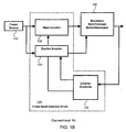
- A conventional motor control system having a position sensor is shown in Fig. 1A. The primary components of the system include a
power source 110, acontroller 120, a motor/generator 130 and a speed/position sensor 140. The Motor/Generator and Starter/ Generator terms are used interchangeably in the following descriptions and claims. Thecontroller 120 includes ainverter controls 126 that receives signals from the sensor 140 (e.g., speed/rotor position) and the motor/generator (e.g., current, voltage). These signals are used to control themain inverter 122 and exciterinverter 124, thereby providing a conventional closed loop system to regulate the torque/speed/current/voltage of the motor/generator 130, as will be appreciated by those skilled in the art. - Fig. 1B illustrates a block diagram of a sensorless system. As is apparent from the block diagram, the sensor and related signals to the
controller 120 are absent. Those skilled in the art will appreciate that this requires thecontroller 120 to process the rotor position/speed of the motor/generator to allow closed loop torque/speed regulation or to exclude certain control functions (e.g., torque control) or operate in an open loop mode. - However, sensorless motor control techniques can increase system reliability and eliminate the need for extra wiring in the system. In addition these techniques will eliminate the need for a position sensor and also reduce the system cost. A sensorless motor control technique is a more flexible/adaptable solution for a motor drive system than one that relies on a separate position sensor. It is particularly valuable for aircraft system where increased reliability and reduction of weight (e.g., through elimination of the sensor and additional wiring) are extremely important.
- Motor controller applications in systems with existing electrical machines can use a sensorless motor control scheme. For example, sensorless control systems are advantageous in retrofit applications, where a sensor and appropriate wiring may be unavailable and not easily installed. Some of these systems have synchronous generators that can be used as a motor/generator but they do not have discrete sensors. Additional applications for this technique include motor controllers in the environmental control systems, electric power systems, industrial drive systems, and the like.
- U.S. Patent No. 5,920,162 issued to Hanson et al. describes a system that utilizes feed through from the exciter winding of twice the fundamental frequency of excitation thereof which is detected synchronously in one of a plurality of stator phase windings of a main motor generator. The one of a plurality of stator phase windings is maintained in a non-commutated state during operation as a motor to determine rotor position of the main motor generator for control of commutation of current in all other commutated stator phase windings, The amplitude modulation of the voltage across each stator phase winding which is maintained in a non-commutated state represents the rotary position of the rotor of the main motor generator which is used to control commutation of current flow in an at least one and preferably all remaining commutated stator phase.
- However, although the above-described system operates as in a sensorless mode, it requires that the position sensing take place only on the non-commutated stator windings. Accordingly, the position sensor emulation must shift from phase to phase as respective phases are commutated, which complicates the sensor emulation. Therefore, it is desired to have a sensor emulation technique and sensorless control system that truly emulates a continuous position sensor and is not dependent on the commutated state of the stator windings. Further, the prior art sensorless systems fail to provide an initial position sensing, which is beneficial at startup under high load torque of the motor/generator. Other examples of prior art systems can be found disclosed in US-A-5608300 and EP-A-0748039.
- In order to solve the problems associated with the prior art, the present invention provides a position sensor emulator for synchronous machines with a wound rotor , the position sensor emulator comprises:
- a first bandpass filter that filters phase voltage signals from a stator of a synchronous machine, wherein said synchronous machine is used simultaneously as a motor and as a position sensor; and
- a converter that converts the filtered phase voltages into balanced two-phase quadrature signals;
- a rectifier that rectifies exciter voltage signals of the synchronous machine; and
- a second bandpass filter that filters the rectified exciter voltage signals to generate a reference signal.
- Preferably, the first and second bandpass filters have a fixed passband, wherein the fixed passband is defined as:

wherein f is the passband, Nph is a number of phases in an exciter stator, fex is the frequency of the exciter voltage, and wet is the top electrical angular speed of the stator of the synchronous machine. - Preferably, the first bandpass filter has a center frequency that tracks a frequency component containing position information, wherein the center frequency is defined as:

wherein f is the passband, Nph is a number of phases in an exciter stator, fex the frequency of the exciter voltage, and we is an electrical angular speed of the stator of the synchronous machine.
Preferably, the two-phase quadrature signals and the reference signal are used as inputs to emulate a resolver in a drive system for the synchronous machine. - The present invention further provides a method for emulating a position sensor for a synchronous machine with a wound rotor, the method comprises the steps of:
- bandpass filtering phase voltage signals from a stator of a synchronous machine, wherein said synchronous machine is used simultaneously as a motor and as a position sensor;
- converting the filtered phase voltages into balanced two-phase quadrature signals;
- rectifying exciter voltage signals of the synchronous machine; and
- bandpass filtering the rectified exciter voltage signals to generate a reference signal.
- Preferably, the bandpass filtering of the phase voltage signals and of the rectified exciter voltage signals has a centre frequency that tracks a frequency component containing position information, and wherein the center frequency is defined as:

wherein f is the passband, Nph is a number of phases in an exciter stator, fex is the frequency of the exciter voltage, and we is an electrical angular speed of the stator of the synchronous machine.
Preferably, the two-phase quadrature signals and the reference signal are used as inputs to emulate a resolver in a drive system for the synchronous machine. - In the drawings:
- FIG. 1A is a conventional system using a position sensor;
- FIG. 1B is a conventional sensorless system;
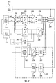
- FIG. 2 is a block diagram of a position sensor emulator and related system according to an embodiment of the present invention;
- FIG. 3 is a block diagram of a position sensor emulator and related system according to another embodiment of the present invention;
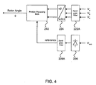
- FIG. 4 is a block diagram of showing details of an embodiment of the position sensor emulator and position processing block;
- Fig. 5 is an alternative embodiment of a position sensor emulator according to the present invention;
- Fig. 6 is a screen capture of waveforms illustrating the starting condition of a test system using a conventional discrete position sensor; and
- Fig. 7 is a screen capture of waveforms illustrating the starting condition of a test system using a position sensor emulator according to the present invention.
- Aspects of the invention are disclosed in the accompanying description. Alternate embodiments may be devised without departing from the scope of the invention.
- In the following description and accompanying drawings like elements are denoted with similar reference numbers. Further, well-known elements and related explanations are omitted so as not to obscure the inventive concepts presented herein.
- FIG. 2. illustrates block diagram of a position sensor emulator according to an embodiment of the present invention. The present invention provides a sensorless system that emulates a resolver-type position sensor by using the similarity between the main rotor of the synchronous machine and a position sensor or resolver. Those skilled in the art will appreciate that controlled AC power from the
exciter power inverter 210 is applied to the field winding of the rotor of the motor/generator 230 resulting in the main rotor behaving as a position sensor, due to its salient construction. This reaction is similar to a resolver-type position sensor. Accordingly, the sensorless system of the present invention continuously detects the voltages on the main stator phase windings of the motor/generator 230 to produce a set of signals that define the rotor position. The signals are obtained from the stator voltage of the motor/ generator after being fed throughbandpass filter 222 andconverter 224. For example,converter 224 can use the well known Clarke transformation (a,b,c/α,β) that converts three-phase quantities (a,b,c) into balanced two-phase quadrature quantities (α,β). Additionally, the exciter voltage from theexciter power supply 210 is passed throughrectifier 226 andbandpass filter 228. The output signals from theconverter 224 andbandpass filter 228 are fed to aposition processing block 240. Those skilled in the art will appreciate that theposition sensor emulator 220 comprises elements 222-228. However, if only the balanced two-phase quadrature quantities (i.e., sine and cosine signals) are required for feedback to the drive system, thenelements position sensor emulator 220 of the present invention provides output signals that emulate signals of a resolver. Therefore, theposition processing block 240 can be a conventional position processing block. A more detailed description of these components is provided below in relation to Figs. 4 and 5. - Those skilled in the art will appreciate that the remaining portion of the block diagram is an exemplary diagram of a typical inverter and control system for a motor/
generator 230. Therefore, the remaining components will not be described in detail. As shown in this configuration, the rotor position feedback signal is fed into the rotorspeed processing block 242, which in turn is fed into the Current vs.Rotor Speed schedule 244 that generates an appropriate current reference signal for the forward loop of the controller. Both quadrature (Iqref) and direct (Idref) axis current commands are summed bysummers 250 with the inner loop current feedback supplied fromsignal converters converter 246 can use the previously described Clarke transformation andconverter 248 can use the well known Park transformation (α,β /d,q) that converts vectors in 2-phase orthogonal stationary system (α,β) into the rotating reference frame (d,q) using the angle θ of the rotating frame. Corresponding inverse Clarke and Park transformations can be used inconverters summers 250 are supplied torespective PID regulators 252, which in turn provide command signals toconverters digital PID regulator 252 that uses the current schedule demand to generate the signals needed to drive theinverter 258. The control scheme presented functions with a current regulator implemented in d-q frame.Converters generator 230. Although, the above referenced control and inverter system has shown specific elements such as a PID controllers and PWM inverter, those skilled in the art will appreciate that many variations of the controller/inverter configuration are known. Further, the present invention is not limited to a particular controller/inverter scheme because it serves as a true emulator for a position sensor. Therefore, the present invention serves to replace the position sensor signals in conventional systems and is designed to be compatible with control/ inverter schemes that use a position sensor for control. - Fig 2 shows a first configuration of the position sensor emulator and motor/ generator control system according to the present invention. In this configuration a
switch 260 is used to alter the control scheme in a high speed / zero and low speed condition. When the rotor of motor/generator 230 approaches a certain speed condition (e.g., 10%-25% of top speed)switch 260 changes the rotor position feedback for the inner loop from the zero and low speedposition processing block 240 to the high speedposition processing block 262. The high-speedposition processing block 262 can be accomplished using conventional techniques (e.g., counter EMF). Accordingly, a detailed description of this element is also omitted. - Fig. 3 is a block diagram of a position sensor emulator and related system according to another embodiment of the present invention. In this configuration all elements are the same and operate the same. However, the
switch 260 and high speedposition sensor emulator 262 is eliminated in this configuration. Accordingly, theposition sensor emulator 220 andposition processing block 240 are used throughout the speed range of thestarter generator 230. - The main stator phase voltages contain three frequency components: the frequency corresponding to the mechanical speed, the inverter switching frequency and a frequency coupled into the main stator from the field winding containing the rotor position information. Therefore, the rotor position/ speed can be obtained by proper detection and processing of the frequency components in the main stator phase voltages of the motor/
generator 230. Accordingly, the present invention emulates a resolver-type position sensor by using the similarity between the main rotor of the brushless synchronous machine and a position sensor or resolver, as previously noted. - Referring to Fig. 4, an exemplary embodiment of a position sensor emulator for a synchronous motor/generator is shown. Specifically, the blocks in Fig. 4 correspond to the blocks in the dashed regions of Figs. 2 and 3. Those skilled in the art will appreciate that the position sensor emulator shown in Fig. 4 can be used with both system configurations shown in Figs. 2 and 3. The
bandpass filter 222A receives inputs from the phase voltages (Va, Vb, Vc) and filters these inputs for the desired frequency. In this embodiment, the pass frequencies correspond to the following equation:
in which f is the pass frequency of the filter; Nph is the number of phases in the exciter stator; fex is the frequency of the exciter voltage; and ω et is the top electrical angular speed of the motor/generator stator (e.g., 2x mechanical speed for a 4-pole machine). For example, in a system having a single phase exciter stator operating at 400 Hz and a top electrical angular speed of the main stator of the motor/generator of 250 Hz, the resulting pass frequencies range would be:
Those skilled in the art will appreciate that this is merely an example for a specific configuration and operating condition for a specific motor/generator. Therefore, the above example is provided merely for explanation and not limitation of the present invention. - Referring back to Fig. 4, the filtered signals from
bandpass filter 222A are passed toconverter 224 that converts the filtered three-phase voltage signals (a,b,c) into balanced two-phase quadrature quantities (α,β), as noted above. These types of conversions/transformations are well known in the art. For example, this conversion can be accomplished as follows:

Further details regarding the above-described equations can be found in standard textbooks such as Krause et al., Analysis of Electric Machinery, IEEE press, 1995, pages 135-161, which is incorporated herein by reference. Additionally, if the system is balanced the transformation can be reduced to the following equations:

which simplifies the calculation of the conversion further. The Vα and Vβ are equivalent to the sine and cosine outputs of a conventional resolver. The reference signal is provided from the exciter voltage, which is rectified byrectifier 226 and filtered bybandpass filter 228A. Typically,bandpass filter 228A will have the same filter characteristics asbandpass filter 222A. Accordingly, the same equation would apply to bothfilters position processing block 240 can be implemented by using conventional techniques and equipment. For example, an Analog Devices AD2S80A Resolver-to-Digital converter can be used as theposition processing block 240, which receives the emulated signals from the position sensor emulator and converts these signals into a rotor position (i.e., rotor angle). Alternatively, an algorithm can be used to extract the angular position, such as:
- Referring to Fig. 5, an alternative embodiment of a position sensor emulator is shown. Those skilled in the art will appreciate that the position sensor emulator shown in Fig. 5 can also be used with both system configurations shown in Figs. 2 and 3. The position sensor emulator according to this embodiment also includes a
first bandpass filter 222B that filters phase voltage signals from a stator of asynchronous machine 230. Aconverter 224 converts the filtered phase voltages (a, b, c) into balanced two-phase quadrature signals (α, β). Arectifier 226 rectifies the exciter voltage signals of thesynchronous machine 230. Asecond bandpass filter 228B filters the rectified exciter voltage signals to generate a reference signal. With the exception offilters - However, in this embodiment the
bandpass filters synchronous machine 230 changes, so does the center frequency of thebandpass filters 
Alternatively, the center frequency can be defined as:
wherein f is the passband, Nph is a number of phases in an exciter stator, fex is the frequency of the exciter voltage, and ω e is the electrical angular speed of the stator of thesynchronous machine 230. - Further, those skilled in the art will appreciate that other combinations of devices can be added or altered without departing from the scope of the present invention. For example, the position sensor emulator of the present invention can be implemented in an analog, a digital or hybrid configuration. The position sensor can be integrated into the software/hardware of a digital drive system as the signals required (e.g., stator voltage, exciter voltage) will typically be available in both analog and digital form in the drive. The position sensor emulator of the present invention can be used in any drive system that requires torque, speed, and/or position control. For example, aircraft, aerospace, industrial, environmental and commercial power/control systems all meet these requirements, as will be appreciated by those skilled in the art.
- Additionally, those skilled in the art will recognize that methods to practice the present invention are apparent from the foregoing description. For example, according to another embodiment of the invention, a method for emulating a position sensor is provided. The method for emulating a position sensor comprises bandpass filtering phase voltage signals from a stator of a synchronous machine; converting the filtered phase voltages into balanced two-phase quadrature signals; rectifying exciter voltage signals of the synchronous machine; and bandpass filtering the rectified exciter voltage signals to generate a reference signal.
- Further, many variations can be made to the above steps without departing from the scope of the invention. For example, the bandpass filtering can be either fixed or tracking, as discussed above. Additionally, switching position feedback from the position sensor emulation during a zero and low speed condition, to a high speed control scheme that does not use the position sensor emulator can be performed, also discussed above in regard to Fig. 4.
- Additionally, those skilled in the art, will appreciate that the frequency of voltage supplied to the starter/ generator exciter can be modified, increased or decreased (including zero frequency), during the start to achieve results equivalent with the filtering methods described herein. Thus, the fixed bandpass filter configuration can "track" the frequency component containing position information because this frequency can be adjusted to coincide with a fixed bandpass filter by increasing or decreasing the exciter frequency in accordance with the speed change of the synchronous machine.
- Fig. 6 shows a screen capture of waveforms illustrating the starting condition of a test system using a conventional discrete position sensor. The top waveform is the stator current. The center waveform is the sensor output and the bottom waveform is the torque generated by the synchronous machine.
- Fig. 7 is a screen capture of waveforms illustrating the starting condition of a test system using a position sensor emulator according to the present invention. The top waveform is the stator current. The center waveform is the emulator output and the bottom waveform is the torque generated by the synchronous machine. Fig.7 illustrates several important qualities achieved by the present invention. For example, it is clear that the emulator system works even at zero speed as can be seen from the start point. Additionally, the emulator was used in direct replacement of the sensor and was not dependent on the commutation scheme of the inverter, therefore no other alterations to the test system were necessary. Also, as can be seen, the output of the emulator tracks the output of the sensor and the torque output of the synchronous machine is controlled from zero speed and throughout the acceleration of the synchronous machine.
- The foregoing illustrates the principles of the invention. It will be appreciated by those skilled in the art that various arrangements of the present invention can be designed. For example, the band of the bandpass filters and converters can be implemented in analog, digital, or hybrid configurations. Those skilled in the art will appreciate that the filters and converters can be implemented in software and/or hardware or in a single device such as an application specific integrated circuit (ASIC). The band of the filters can be established in narrower or broader ranges than the examples provide. Those skilled in the art will appreciate that the ranges can be optimized based upon the specific requirements of the system and design of the synchronous machine (e.g., number of poles, and the like), which form the basis for calculating the appropriate passband frequencies. Therefore, the scope of the invention is not limited by the foregoing description but is defined solely by the appended claims.

wherein f is the passband, Nph is a number of phases in an exciter stator, fex is the frequency of the exciter voltage, and Wet is the top electrical angular speed of the stator of the synchronous machine.
Claims (8)
- A position sensor emulator (220) for synchronous machines with a wound rotor the position sensor emulator comprising:a first bandpass filter (222) that filters phase voltage signals from a stator of a synchronous machine (230), wherein said synchronous machine (230) is used simultaneously as a motor and as a position sensor; anda converter (224) that converts the filtered phase voltages (a, b, c) into balanced two-phase quadrature signals;a rectifier (226) that rectifies exciter (210) voltage signals of the synchronous -machine (230); anda second bandpass filter (228) that filters the rectified exciter voltage signals to generate a reference signal.
- The position sensor emulator of claim 1, wherein the first (222) and second (228) bandpass filters have a fixed passband, wherein the fixed passband is defined as:

wherein f is the passband, Nph is a number of phases in an exciter stator, fex is the frequency of the exciter voltage, and wet is the top electrical angular speed of the stator of the synchronous machine. - The position sensor emulator of claim 1, wherein the first bandpass filter (222) has a centre frequency that tracks a frequency component containing position information, wherein the center frequency is defined as:

wherein f is the passband, Nph is a number of phases in an exciter stator, fex the frequency of the exciter voltage, and we is an electrical angular speed of the stator of the synchronous machine. - The position sensor emulator of claim 1, wherein the two-phase quadrature signals and the reference signal are used as inputs to emulate a resolver in a drive system for the synchronous machine (230).
- A method for emulating a position sensor for a synchronous machine with a wound rotor, the method comprising the steps of:bandpass filtering phase voltage signals from a stator of a synchronous machine (230), wherein said synchronous machine (230) is used simultaneously as a motor and as a position sensor;converting the filtered phase voltages (a, b, c) into balanced two-phase quadrature signals;rectifying exciter (210) voltage signals of the synchronous machine (230); andbandpass filtering the rectified exciter voltage signals to generate a reference signal.
- The method of claim 5, wherein the bandpass filtering of the phase voltage signals (a, b, c) and of the rectified exciter voltage signals has a fixed passband and, wherein the fixed passband is defined as:

wherein f is the passband, Nph is a number of phases in an exciter stator, fex is the frequency of the exciter voltage, and Wet is the top electrical angular speed of the stator of the synchronous machine. - The method of claim 5, wherein the bandpass filtering of the phase voltage signals (a, b, c) and of the rectified exciter voltage signals has a centre frequency that tracks a frequency component containing position information, and wherein the center frequency is defined as:

wherein f is the passband, Nph is a number of phases in an exciter stator, fex is the frequency of the exciter voltage, and we is an electrical angular speed of the stator of the synchronous machine. - The method of claim 5, wherein the two-phase quadrature signals and the reference signal are used as inputs to emulate a resolver in a drive system for the synchronous machine.
Applications Claiming Priority (3)
| Application Number | Priority Date | Filing Date | Title |
|---|---|---|---|
| US10/244,496 US6809496B2 (en) | 2002-09-16 | 2002-09-16 | Position sensor emulator for a synchronous motor/generator |
| US244496 | 2002-09-16 | ||
| PCT/US2003/030806 WO2004025821A2 (en) | 2002-09-16 | 2003-09-15 | Position sensor emulator for a wound rotor synchronous motor/ generator |
Publications (2)
| Publication Number | Publication Date |
|---|---|
| EP1540810A2 EP1540810A2 (en) | 2005-06-15 |
| EP1540810B1 true EP1540810B1 (en) | 2006-12-13 |
Family
ID=31991905
Family Applications (1)
| Application Number | Title | Priority Date | Filing Date |
|---|---|---|---|
| EP03795712A Expired - Lifetime EP1540810B1 (en) | 2002-09-16 | 2003-09-15 | Position sensor emulator for a synchronous motor/ generator with a wound rotor |
Country Status (7)
| Country | Link |
|---|---|
| US (1) | US6809496B2 (en) |
| EP (1) | EP1540810B1 (en) |
| JP (1) | JP2005539473A (en) |
| AT (1) | ATE348442T1 (en) |
| AU (1) | AU2003277093A1 (en) |
| DE (1) | DE60310423T2 (en) |
| WO (1) | WO2004025821A2 (en) |
Families Citing this family (35)
| Publication number | Priority date | Publication date | Assignee | Title |
|---|---|---|---|---|
| US6950321B2 (en) * | 2003-09-24 | 2005-09-27 | General Motors Corporation | Active damping control for L-C output filters in three phase four-leg inverters |
| JP4113848B2 (en) * | 2004-02-18 | 2008-07-09 | 三菱電機株式会社 | Motor generator control device |
| US7045986B2 (en) * | 2004-02-20 | 2006-05-16 | Honeywell International Inc. | Position sensing method and apparatus for synchronous motor generator system |
| US7184927B2 (en) | 2004-03-26 | 2007-02-27 | Honeywell International Inc. | Adaptive position sensing method and apparatus for synchronous motor generator system |
| US7208908B2 (en) * | 2004-07-12 | 2007-04-24 | Honeywell International Inc. | Apparatus and method to control torque and voltage of an AC machine |
| US20060043923A1 (en) * | 2004-08-31 | 2006-03-02 | Baker Donal E | Performance enhancement for motor field oriented control system |
| US20070244683A1 (en) * | 2005-08-19 | 2007-10-18 | Honeywell International Inc. | Device simulating operation of a machine that functions as either a motor or a generator |
| US7339344B2 (en) * | 2005-08-25 | 2008-03-04 | International Rectifier Corporation | Self tuning method and apparatus for permanent magnet sensorless control |
| WO2007092466A2 (en) * | 2006-02-03 | 2007-08-16 | Bae Systems Land & Armaments L.P. | Nonlinear motor control techniques |
| US7132816B1 (en) * | 2006-02-20 | 2006-11-07 | Hamilton Sundstrand Corporation | Brushless wound field synchronous machine rotor position tracking with exciter stator current harmonic tracking |
| US7514806B2 (en) * | 2007-06-05 | 2009-04-07 | Honeywell International Inc. | Engine start system with quadrature AC excitation |
| US7571072B2 (en) * | 2007-07-02 | 2009-08-04 | Honeywell International Inc. | Energy based position and speed self-sensing method and apparatus for synchronous machine |
| EP2023479B1 (en) * | 2007-08-06 | 2014-04-16 | Baumüller Nürnberg Gmbh | System for seamless velocity and/or location determination including standstill for a permanent magnet rotor of an electric machine |
| DK2104220T3 (en) * | 2008-03-19 | 2010-03-22 | Abb Schweiz Ag | Method for operating a converter circuit and device for carrying out the method |
| GB2460724B (en) * | 2008-06-13 | 2011-04-13 | Ehsan Abdi Jalebi | Torque-sensing control system for a brushless doubly fed machine (BFDM) |
| FI121721B (en) * | 2008-09-04 | 2011-03-15 | Abb Oy | Method and arrangement for determining engine speed |
| GB0908112D0 (en) * | 2009-05-12 | 2009-06-24 | Peto Raymond J | Apparatus and method for determining speed of a motor, generator or alternator |
| ES2592178T3 (en) * | 2009-06-19 | 2016-11-28 | Vestas Wind Systems A/S | Method for determining the rotor position of an electric generator in a wind turbine |
| US8975878B2 (en) * | 2010-12-23 | 2015-03-10 | Caterpillar Inc. | Switched reluctance generator integrated controls |
| DE102011007331A1 (en) * | 2011-04-13 | 2012-10-18 | Robert Bosch Gmbh | Method for detecting a rotation of a rotor of a generator |
| ES2811533T3 (en) | 2012-03-05 | 2021-03-12 | Novanta Corp | Phase estimation method and apparatus for it |
| US8866449B1 (en) * | 2013-06-10 | 2014-10-21 | Hamilton Sundstrand Corporation | Sensor PM electrical machines |
| CN105659491B (en) * | 2013-10-22 | 2018-09-07 | 三菱电机株式会社 | motor control unit |
| US9362845B2 (en) * | 2013-12-23 | 2016-06-07 | Generac Power Systems, Inc. | Method of operating a single-phase generator in parallel with an inventor |
| US10027261B2 (en) * | 2014-03-05 | 2018-07-17 | Nidec Servo Corporation | Motor apparatus |
| US20150309096A1 (en) * | 2014-04-29 | 2015-10-29 | Lsis Co., Ltd. | Instantaneous power monitoring system for hvdc system |
| US10305356B2 (en) * | 2014-09-26 | 2019-05-28 | The Boeing Company | Synchronous machine with common motor/generator exciter stage |
| US9595903B2 (en) * | 2015-03-20 | 2017-03-14 | General Electric Company | Controller for motor |
| CN107294437A (en) * | 2017-06-21 | 2017-10-24 | 苏州华铭威智能科技有限公司 | The startup method and control system of a kind of brushless electric machine |
| FR3073691B1 (en) * | 2017-11-16 | 2020-07-17 | Renault S.A.S | METHOD FOR CONTROLLING A SYNCHRONOUS ELECTRIC MACHINE |
| CN109656152B (en) * | 2018-12-25 | 2021-10-15 | 西安翔迅科技有限责任公司 | Engine intake/exhaust valve actuator simulation assembly system and method based on digital control |
| CN113612402A (en) * | 2021-08-09 | 2021-11-05 | 山特电子(深圳)有限公司 | Three-phase inversion control system and control method |
| CN116895203A (en) * | 2023-05-30 | 2023-10-17 | 大唐水电科学技术研究院有限公司 | Generator rotor winding RSO characteristic simulator and operation method |
| US12549115B2 (en) * | 2023-09-29 | 2026-02-10 | Stmicroelectronics International N.V. | Systems, apparatuses, and methods to perform startup step detection in an internal permanent magnet synchronous machine |
| CN117516365B (en) * | 2023-11-03 | 2024-10-22 | 武汉光谷航天三江激光产业技术研究院有限公司 | ANSYS simulation-based angle sensor fuzzy calibration method and system |
Family Cites Families (23)
| Publication number | Priority date | Publication date | Assignee | Title |
|---|---|---|---|---|
| US3748555A (en) * | 1972-05-01 | 1973-07-24 | Westinghouse Electric Corp | Protective circuit for brushless synchronous motors |
| EP0228535A1 (en) * | 1985-12-04 | 1987-07-15 | Siemens Aktiengesellschaft | Method and device to determine the flux angle of an induction machine i.e. to operate the machine according to position |
| US5182499A (en) * | 1990-10-25 | 1993-01-26 | Matsushita Electric Industrial Co., Ltd. | Sensorless brushless motor |
| US5430362A (en) | 1993-05-12 | 1995-07-04 | Sundstrand Corporation | Engine starting system utilizing multiple controlled acceleration rates |
| US5384527A (en) | 1993-05-12 | 1995-01-24 | Sundstrand Corporation | Rotor position detector with back EMF voltage estimation |
| US5495163A (en) | 1993-05-12 | 1996-02-27 | Sundstrand Corporation | Control for a brushless generator operable in generating and starting modes |
| US5493200A (en) | 1993-05-12 | 1996-02-20 | Sundstrand Corporation | Control for a brushless generator |
| US5363032A (en) | 1993-05-12 | 1994-11-08 | Sundstrand Corporation | Sensorless start of synchronous machine |
| US5581168A (en) * | 1993-05-12 | 1996-12-03 | Sundstrand Corporation | Starter/generator system with DC link current control |
| US5444349A (en) | 1993-05-12 | 1995-08-22 | Sundstrand Corporation | Starting control for an electromagnetic machine |
| US5495162A (en) | 1993-05-12 | 1996-02-27 | Sundstrand Corporation | Position-and-velocity sensorless control for starter generator electrical system using generator back-EMF voltage |
| US5428275A (en) | 1993-05-12 | 1995-06-27 | Sundstrand Corporation | Controlled starting method for a gas turbine engine |
| US5461293A (en) | 1993-05-12 | 1995-10-24 | Sundstrand Corporation | Rotor position detector |
| US5594322A (en) | 1993-05-12 | 1997-01-14 | Sundstrand Corporation | Starter/generator system with variable-frequency exciter control |
| JP3381408B2 (en) * | 1993-10-26 | 2003-02-24 | トヨタ自動車株式会社 | Electric angle detecting device and synchronous motor driving device using the same |
| FR2714234B1 (en) * | 1993-12-16 | 1996-08-23 | Telemecanique | Power control system for an asynchronous motor. |
| US5585709A (en) * | 1993-12-22 | 1996-12-17 | Wisconsin Alumni Research Foundation | Method and apparatus for transducerless position and velocity estimation in drives for AC machines |
| MY120887A (en) | 1995-06-08 | 2005-12-30 | Sony Corp | Rotation position detecting device and motor device. |
| US5920162A (en) | 1996-08-05 | 1999-07-06 | Sundstrand Corporation | Position control using variable exciter feed through |
| US6271720B1 (en) * | 1998-09-02 | 2001-08-07 | Linear Technology Corporation | Operational filter building block |
| US6081091A (en) * | 1999-03-08 | 2000-06-27 | Motorola, Inc. | Motor controller, integrated circuit, and method of controlling a motor |
| WO2001015311A1 (en) * | 1999-08-20 | 2001-03-01 | Mitsubishi Denki Kabushiki Kaisha | Synchronous motor control device and method |
| KR100354775B1 (en) * | 2000-03-25 | 2002-11-04 | 엘지전자 주식회사 | Speed control apparatus of a synchronous reluctance motor |
-
2002
- 2002-09-16 US US10/244,496 patent/US6809496B2/en not_active Expired - Lifetime
-
2003
- 2003-09-15 EP EP03795712A patent/EP1540810B1/en not_active Expired - Lifetime
- 2003-09-15 AU AU2003277093A patent/AU2003277093A1/en not_active Abandoned
- 2003-09-15 DE DE60310423T patent/DE60310423T2/en not_active Expired - Lifetime
- 2003-09-15 JP JP2004536636A patent/JP2005539473A/en not_active Withdrawn
- 2003-09-15 AT AT03795712T patent/ATE348442T1/en not_active IP Right Cessation
- 2003-09-15 WO PCT/US2003/030806 patent/WO2004025821A2/en not_active Ceased
Also Published As
| Publication number | Publication date |
|---|---|
| DE60310423T2 (en) | 2007-10-11 |
| US6809496B2 (en) | 2004-10-26 |
| DE60310423D1 (en) | 2007-01-25 |
| US20040052217A1 (en) | 2004-03-18 |
| AU2003277093A8 (en) | 2004-04-30 |
| WO2004025821A2 (en) | 2004-03-25 |
| AU2003277093A1 (en) | 2004-04-30 |
| EP1540810A2 (en) | 2005-06-15 |
| JP2005539473A (en) | 2005-12-22 |
| WO2004025821A3 (en) | 2004-07-15 |
| ATE348442T1 (en) | 2007-01-15 |
Similar Documents
| Publication | Publication Date | Title |
|---|---|---|
| US6809496B2 (en) | Position sensor emulator for a synchronous motor/generator | |
| US7045986B2 (en) | Position sensing method and apparatus for synchronous motor generator system | |
| EP1728315B1 (en) | Adaptive position sensing method and apparatus for synchronous motor generator system | |
| US5920162A (en) | Position control using variable exciter feed through | |
| US5747971A (en) | Position and velocity sensorless control for a motor generator system operated as a motor using exciter impedance | |
| US5594322A (en) | Starter/generator system with variable-frequency exciter control | |
| US5495163A (en) | Control for a brushless generator operable in generating and starting modes | |
| US5461293A (en) | Rotor position detector | |
| US5488286A (en) | Method and apparatus for starting a synchronous machine | |
| US7034497B2 (en) | Carrier injection sensorless control of aircraft variable frequency wound field synchronous starter/generators | |
| EP2840702B1 (en) | Systems for wound field synchronous machines with zero speed rotor position detection during start for motoring and improved transient response for generation | |
| KR100795382B1 (en) | System and method for controlling a permanent magnet rotating machine in a sensorless manner | |
| US4937508A (en) | VSCF start system with precision voltage | |
| EP1774646B1 (en) | Apparatus and method to control torque and voltage of an ac machine | |
| US6301136B1 (en) | Floating flame controller | |
| US4484126A (en) | Induction motor controller | |
| Das et al. | Observer-based stator-flux-oriented vector control of cycloconverter-fed synchronous motor drive | |
| US5006768A (en) | Synchronous motor control | |
| JP2005117756A (en) | DC voltage detection circuit failure diagnosis device and motor control system | |
| KR100289430B1 (en) | Method and apparatus for speed control of synchronous reluctance motor | |
| JPH10229687A (en) | Variable speed control device for induction motor | |
| JP4448300B2 (en) | Control device for synchronous machine | |
| EP0073839B1 (en) | Control device for synchronous motor | |
| SU1332427A1 (en) | Electric drive | |
| SU1138916A1 (en) | Variable-frequency synchronous electric drive |
Legal Events
| Date | Code | Title | Description |
|---|---|---|---|
| PUAI | Public reference made under article 153(3) epc to a published international application that has entered the european phase |
Free format text: ORIGINAL CODE: 0009012 |
|
| 17P | Request for examination filed |
Effective date: 20050324 |
|
| AK | Designated contracting states |
Kind code of ref document: A2 Designated state(s): AT BE BG CH CY CZ DE DK EE ES FI FR GB GR HU IE IT LI LU MC NL PT RO SE SI SK TR |
|
| AX | Request for extension of the european patent |
Extension state: AL LT LV MK |
|
| DAX | Request for extension of the european patent (deleted) | ||
| GRAP | Despatch of communication of intention to grant a patent |
Free format text: ORIGINAL CODE: EPIDOSNIGR1 |
|
| RTI1 | Title (correction) |
Free format text: POSITION SENSOR EMULATOR FOR A SYNCHRONOUS MOTOR/ GENERATOR WITH A WOUND ROTOR |
|
| GRAS | Grant fee paid |
Free format text: ORIGINAL CODE: EPIDOSNIGR3 |
|
| GRAA | (expected) grant |
Free format text: ORIGINAL CODE: 0009210 |
|
| AK | Designated contracting states |
Kind code of ref document: B1 Designated state(s): AT BE BG CH CY CZ DE DK EE ES FI FR GB GR HU IE IT LI LU MC NL PT RO SE SI SK TR |
|
| PG25 | Lapsed in a contracting state [announced via postgrant information from national office to epo] |
Ref country code: IT Free format text: LAPSE BECAUSE OF FAILURE TO SUBMIT A TRANSLATION OF THE DESCRIPTION OR TO PAY THE FEE WITHIN THE PRESCRIBED TIME-LIMIT;WARNING: LAPSES OF ITALIAN PATENTS WITH EFFECTIVE DATE BEFORE 2007 MAY HAVE OCCURRED AT ANY TIME BEFORE 2007. THE CORRECT EFFECTIVE DATE MAY BE DIFFERENT FROM THE ONE RECORDED. Effective date: 20061213 Ref country code: FI Free format text: LAPSE BECAUSE OF FAILURE TO SUBMIT A TRANSLATION OF THE DESCRIPTION OR TO PAY THE FEE WITHIN THE PRESCRIBED TIME-LIMIT Effective date: 20061213 Ref country code: CH Free format text: LAPSE BECAUSE OF FAILURE TO SUBMIT A TRANSLATION OF THE DESCRIPTION OR TO PAY THE FEE WITHIN THE PRESCRIBED TIME-LIMIT Effective date: 20061213 Ref country code: DK Free format text: LAPSE BECAUSE OF FAILURE TO SUBMIT A TRANSLATION OF THE DESCRIPTION OR TO PAY THE FEE WITHIN THE PRESCRIBED TIME-LIMIT Effective date: 20061213 Ref country code: LI Free format text: LAPSE BECAUSE OF FAILURE TO SUBMIT A TRANSLATION OF THE DESCRIPTION OR TO PAY THE FEE WITHIN THE PRESCRIBED TIME-LIMIT Effective date: 20061213 Ref country code: SK Free format text: LAPSE BECAUSE OF FAILURE TO SUBMIT A TRANSLATION OF THE DESCRIPTION OR TO PAY THE FEE WITHIN THE PRESCRIBED TIME-LIMIT Effective date: 20061213 Ref country code: RO Free format text: LAPSE BECAUSE OF FAILURE TO SUBMIT A TRANSLATION OF THE DESCRIPTION OR TO PAY THE FEE WITHIN THE PRESCRIBED TIME-LIMIT Effective date: 20061213 Ref country code: BE Free format text: LAPSE BECAUSE OF FAILURE TO SUBMIT A TRANSLATION OF THE DESCRIPTION OR TO PAY THE FEE WITHIN THE PRESCRIBED TIME-LIMIT Effective date: 20061213 Ref country code: NL Free format text: LAPSE BECAUSE OF FAILURE TO SUBMIT A TRANSLATION OF THE DESCRIPTION OR TO PAY THE FEE WITHIN THE PRESCRIBED TIME-LIMIT Effective date: 20061213 Ref country code: AT Free format text: LAPSE BECAUSE OF FAILURE TO SUBMIT A TRANSLATION OF THE DESCRIPTION OR TO PAY THE FEE WITHIN THE PRESCRIBED TIME-LIMIT Effective date: 20061213 Ref country code: SI Free format text: LAPSE BECAUSE OF FAILURE TO SUBMIT A TRANSLATION OF THE DESCRIPTION OR TO PAY THE FEE WITHIN THE PRESCRIBED TIME-LIMIT Effective date: 20061213 Ref country code: CZ Free format text: LAPSE BECAUSE OF FAILURE TO SUBMIT A TRANSLATION OF THE DESCRIPTION OR TO PAY THE FEE WITHIN THE PRESCRIBED TIME-LIMIT Effective date: 20061213 |
|
| REG | Reference to a national code |
Ref country code: GB Ref legal event code: FG4D |
|
| REG | Reference to a national code |
Ref country code: CH Ref legal event code: EP |
|
| REG | Reference to a national code |
Ref country code: IE Ref legal event code: FG4D |
|
| REF | Corresponds to: |
Ref document number: 60310423 Country of ref document: DE Date of ref document: 20070125 Kind code of ref document: P |
|
| PG25 | Lapsed in a contracting state [announced via postgrant information from national office to epo] |
Ref country code: SE Free format text: LAPSE BECAUSE OF FAILURE TO SUBMIT A TRANSLATION OF THE DESCRIPTION OR TO PAY THE FEE WITHIN THE PRESCRIBED TIME-LIMIT Effective date: 20070313 Ref country code: BG Free format text: LAPSE BECAUSE OF FAILURE TO SUBMIT A TRANSLATION OF THE DESCRIPTION OR TO PAY THE FEE WITHIN THE PRESCRIBED TIME-LIMIT Effective date: 20070313 |
|
| PG25 | Lapsed in a contracting state [announced via postgrant information from national office to epo] |
Ref country code: ES Free format text: LAPSE BECAUSE OF FAILURE TO SUBMIT A TRANSLATION OF THE DESCRIPTION OR TO PAY THE FEE WITHIN THE PRESCRIBED TIME-LIMIT Effective date: 20070324 |
|
| PG25 | Lapsed in a contracting state [announced via postgrant information from national office to epo] |
Ref country code: PT Free format text: LAPSE BECAUSE OF FAILURE TO SUBMIT A TRANSLATION OF THE DESCRIPTION OR TO PAY THE FEE WITHIN THE PRESCRIBED TIME-LIMIT Effective date: 20070514 |
|
| ET | Fr: translation filed | ||
| NLV1 | Nl: lapsed or annulled due to failure to fulfill the requirements of art. 29p and 29m of the patents act | ||
| REG | Reference to a national code |
Ref country code: CH Ref legal event code: PL |
|
| PLBE | No opposition filed within time limit |
Free format text: ORIGINAL CODE: 0009261 |
|
| STAA | Information on the status of an ep patent application or granted ep patent |
Free format text: STATUS: NO OPPOSITION FILED WITHIN TIME LIMIT |
|
| 26N | No opposition filed |
Effective date: 20070914 |
|
| PG25 | Lapsed in a contracting state [announced via postgrant information from national office to epo] |
Ref country code: MC Free format text: LAPSE BECAUSE OF NON-PAYMENT OF DUE FEES Effective date: 20070930 Ref country code: GR Free format text: LAPSE BECAUSE OF FAILURE TO SUBMIT A TRANSLATION OF THE DESCRIPTION OR TO PAY THE FEE WITHIN THE PRESCRIBED TIME-LIMIT Effective date: 20070314 |
|
| PG25 | Lapsed in a contracting state [announced via postgrant information from national office to epo] |
Ref country code: IE Free format text: LAPSE BECAUSE OF NON-PAYMENT OF DUE FEES Effective date: 20070917 |
|
| PG25 | Lapsed in a contracting state [announced via postgrant information from national office to epo] |
Ref country code: EE Free format text: LAPSE BECAUSE OF FAILURE TO SUBMIT A TRANSLATION OF THE DESCRIPTION OR TO PAY THE FEE WITHIN THE PRESCRIBED TIME-LIMIT Effective date: 20061213 |
|
| PG25 | Lapsed in a contracting state [announced via postgrant information from national office to epo] |
Ref country code: CY Free format text: LAPSE BECAUSE OF FAILURE TO SUBMIT A TRANSLATION OF THE DESCRIPTION OR TO PAY THE FEE WITHIN THE PRESCRIBED TIME-LIMIT Effective date: 20061213 Ref country code: LU Free format text: LAPSE BECAUSE OF NON-PAYMENT OF DUE FEES Effective date: 20070915 |
|
| PG25 | Lapsed in a contracting state [announced via postgrant information from national office to epo] |
Ref country code: HU Free format text: LAPSE BECAUSE OF FAILURE TO SUBMIT A TRANSLATION OF THE DESCRIPTION OR TO PAY THE FEE WITHIN THE PRESCRIBED TIME-LIMIT Effective date: 20070614 Ref country code: TR Free format text: LAPSE BECAUSE OF FAILURE TO SUBMIT A TRANSLATION OF THE DESCRIPTION OR TO PAY THE FEE WITHIN THE PRESCRIBED TIME-LIMIT Effective date: 20061213 |
|
| REG | Reference to a national code |
Ref country code: FR Ref legal event code: PLFP Year of fee payment: 13 |
|
| REG | Reference to a national code |
Ref country code: FR Ref legal event code: PLFP Year of fee payment: 14 |
|
| REG | Reference to a national code |
Ref country code: FR Ref legal event code: PLFP Year of fee payment: 15 |
|
| REG | Reference to a national code |
Ref country code: FR Ref legal event code: PLFP Year of fee payment: 16 |
|
| PGFP | Annual fee paid to national office [announced via postgrant information from national office to epo] |
Ref country code: GB Payment date: 20220920 Year of fee payment: 20 Ref country code: DE Payment date: 20220927 Year of fee payment: 20 |
|
| PGFP | Annual fee paid to national office [announced via postgrant information from national office to epo] |
Ref country code: FR Payment date: 20220926 Year of fee payment: 20 |
|
| P01 | Opt-out of the competence of the unified patent court (upc) registered |
Effective date: 20230525 |
|
| REG | Reference to a national code |
Ref country code: DE Ref legal event code: R071 Ref document number: 60310423 Country of ref document: DE |
|
| REG | Reference to a national code |
Ref country code: GB Ref legal event code: PE20 Expiry date: 20230914 |
|
| PG25 | Lapsed in a contracting state [announced via postgrant information from national office to epo] |
Ref country code: GB Free format text: LAPSE BECAUSE OF EXPIRATION OF PROTECTION Effective date: 20230914 |