EP1540780B1 - Koaxialverbinder eines airbag-initiators - Google Patents
Koaxialverbinder eines airbag-initiators Download PDFInfo
- Publication number
- EP1540780B1 EP1540780B1 EP03788231.3A EP03788231A EP1540780B1 EP 1540780 B1 EP1540780 B1 EP 1540780B1 EP 03788231 A EP03788231 A EP 03788231A EP 1540780 B1 EP1540780 B1 EP 1540780B1
- Authority
- EP
- European Patent Office
- Prior art keywords
- section
- ground terminal
- coaxial connector
- air bag
- protrusions
- Prior art date
- Legal status (The legal status is an assumption and is not a legal conclusion. Google has not performed a legal analysis and makes no representation as to the accuracy of the status listed.)
- Expired - Lifetime
Links
- 239000003999 initiator Substances 0.000 title claims description 31
- 238000003780 insertion Methods 0.000 claims description 32
- 230000037431 insertion Effects 0.000 claims description 32
- 230000013011 mating Effects 0.000 claims description 16
- 239000004020 conductor Substances 0.000 claims description 13
- 229910000859 α-Fe Inorganic materials 0.000 claims description 8
- 239000002184 metal Substances 0.000 claims description 6
- 238000000034 method Methods 0.000 claims 2
- 238000013461 design Methods 0.000 description 3
- 238000004519 manufacturing process Methods 0.000 description 2
- 239000000463 material Substances 0.000 description 2
- 238000012986 modification Methods 0.000 description 2
- 230000004048 modification Effects 0.000 description 2
- 241001481828 Glyptocephalus cynoglossus Species 0.000 description 1
- 230000004888 barrier function Effects 0.000 description 1
- 230000006835 compression Effects 0.000 description 1
- 238000007906 compression Methods 0.000 description 1
- 238000010276 construction Methods 0.000 description 1
- 238000011161 development Methods 0.000 description 1
- 230000018109 developmental process Effects 0.000 description 1
- 238000010348 incorporation Methods 0.000 description 1
- 238000009413 insulation Methods 0.000 description 1
- 210000003127 knee Anatomy 0.000 description 1
- 238000004890 malting Methods 0.000 description 1
- 239000007769 metal material Substances 0.000 description 1
- 238000004806 packaging method and process Methods 0.000 description 1
- 238000007747 plating Methods 0.000 description 1
Images
Classifications
-
- H—ELECTRICITY
- H01—ELECTRIC ELEMENTS
- H01R—ELECTRICALLY-CONDUCTIVE CONNECTIONS; STRUCTURAL ASSOCIATIONS OF A PLURALITY OF MUTUALLY-INSULATED ELECTRICAL CONNECTING ELEMENTS; COUPLING DEVICES; CURRENT COLLECTORS
- H01R29/00—Coupling parts for selective co-operation with a counterpart in different ways to establish different circuits, e.g. for voltage selection, for series-parallel selection, programmable connectors
-
- H—ELECTRICITY
- H01—ELECTRIC ELEMENTS
- H01R—ELECTRICALLY-CONDUCTIVE CONNECTIONS; STRUCTURAL ASSOCIATIONS OF A PLURALITY OF MUTUALLY-INSULATED ELECTRICAL CONNECTING ELEMENTS; COUPLING DEVICES; CURRENT COLLECTORS
- H01R24/00—Two-part coupling devices, or either of their cooperating parts, characterised by their overall structure
- H01R24/58—Contacts spaced along longitudinal axis of engagement
-
- H—ELECTRICITY
- H01—ELECTRIC ELEMENTS
- H01R—ELECTRICALLY-CONDUCTIVE CONNECTIONS; STRUCTURAL ASSOCIATIONS OF A PLURALITY OF MUTUALLY-INSULATED ELECTRICAL CONNECTING ELEMENTS; COUPLING DEVICES; CURRENT COLLECTORS
- H01R33/00—Coupling devices specially adapted for supporting apparatus and having one part acting as a holder providing support and electrical connection via a counterpart which is structurally associated with the apparatus, e.g. lamp holders; Separate parts thereof
- H01R33/05—Two-pole devices
- H01R33/20—Two-pole devices having concentrically or coaxially arranged contacts
-
- H—ELECTRICITY
- H01—ELECTRIC ELEMENTS
- H01R—ELECTRICALLY-CONDUCTIVE CONNECTIONS; STRUCTURAL ASSOCIATIONS OF A PLURALITY OF MUTUALLY-INSULATED ELECTRICAL CONNECTING ELEMENTS; COUPLING DEVICES; CURRENT COLLECTORS
- H01R2103/00—Two poles
Definitions
- the present invention relates to electrical connectors and, more particularly, to a coaxial electrical connector.
- U.S. Patent No. 5, 944, 545 discloses a single pin coaxial initiator, retainer and connector.
- the connector has an arcuate contact piece for contacting the spring loaded arms of the conductive ring of the initiator.
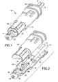
- FIG. 1 there is shown a perspective view of an electrical connector and conductor assembly 10 incorporating features of the present invention.
- the present invention will be described with reference to the exemplary embodiment shown in the drawings, it should be understood that the pres ent invention can be embodied in many alternate forms of embodiments. In addition, any suitable size, shape or type of elements or materials could be used.
- the assembly 10 is provided for connection to a gas generator (not shown), such as a micro gas generator used in a vehicle air bag assembly.
- a gas generator such as a micro gas generator used in a vehicle air bag assembly.
- the assembly- 10 could be used to connect to any- suitable type of elect rical component.
- the assembly 10 generally comprises an electrical connector 12 and two electrical, conductors 14, 15. In alternate embodiment, the assembly could comprise more than two electrical conductors, and/or the conductors could be provided in a cable configuration.
- electrical connector 10 is provided as a coaxial electrical connector.
- the electrical connector 10 comprises a housing 16, a power terminal 18, a ground terminal 20 and a ferrite member 22.
- the electrical connector could comprise additional components.
- the connector 10 forms a mating connector insertion section 11 which is adapted to be inserted into a mating connector of a gas generator initiator.
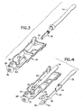
- the housing 16 comprises a first housing member 24 and a second housing member 26.
- the housing 16 forms a front insertion section 28.
- the front insertion section 28 is provided on the first housing member 24.
- the front insertion section includes at a front aperture 30 therethrough.
- the front insertion section 28 also comprises a general annular or C shaped groove portion 32 (see Fig. 4 ) on its exterior side.
- the two housing members 24, 26 are adapted to be snap lock mounted to each other by snap-lock mounting sections 40. When the two housing members 24, 26 are snap lock mounted to each other they capture portions of the terminals 18, 20, ferrite member 22, and conductors 14, 15 therebetween.
- the power terminal 18 is provided as a female contact.
- the terminal 18 is electrically and mechanically connected to the first electrical conductor 14.
- the terminal 18 is inserted into the first housing member 24 such that the front entrance aperture 19 of the terminal 18 is located behind and aligned with the aperture 30 of the front insertion section 28. Any suitable type of female terminal could be used.
- the ferrite member 22 is provided as a tubular ferrule which is located over a portion of the conductor 14. As is known in the art, the ferrite member 22 is provided to prevent an unintentional electrical signal being transmitted by the electrical conductor 14 to the power terminal 18. Any suitable type of ferrite member could be provided.
- the ground terminal 20 generally comprises a one-piece member. Contact portions of the ground terminal 20 could be plated with a suitable plating material.
- the one-piece member is preferably formed from sheet metal which has been stamped and formed into the shaped shown.
- the ground terminal 20 generally comprises a first connection section 34 and a second connection section 36.
- the first connection section 34 is provided for connecting the terminal to the second electrical conductor 15.
- the first connection section 34 is adapted to be compressed or crimped onto the conductor 15.
- any suitable type of connection between the terminal and the electrical conductor 15 could be provided.
- the second connection section 36 is connected to the first connection secton 34 by a bridging section 38.
- the bridging section 38 is contoured to be positioned on an outer side of one of the pair of forward snap lock mounting sections 40 of the first housing member 24.
- the power terminal 18 can be located between the pair of forward mounting sections 40.
- the mounting section 40 can be used to provide an insulation barrier between the terminals 18, 20. More importantly, one of the mounting sections 40 provides a structural support for the inside surface of the bridging section 38.
- the second connection section 36 comprise a general C shaped profile or cross-section.
- the second connection section 36 includes an outwardly extending protrusions 42.
- the second connection section 36 comprises three of the protrusions 42. In an alternate embodiment, more or less than three protrusions could be provided.
- the protrusions 42 are spaced front each other along the outer side of the second connection section 36 with one of the protrusions being located on a top side, another one of the protrusions being located on a bottom side, and a third one of the protrusions being located on a lateral side.
- the protrusions extend radially outward relative to a center axis of the general C shaped section.
- the protrusions 42 comprise a gene ral rounded hill shape.
- the protrusions 42 could comprise any suitable type of shape.
- the front facing sides of the hill shapes could comprise elongated sLopes to help with insertion of the front end of the connector 12 into an initiator.
- the sheet metal material of the second connection sect ion 36 is stamped in as outward direction to form outward deformations of the sheet metal.
- recesses are formed under the outwardly extending hill shapes.
- the second connection section has its outer side freely exposed. Because it is a ground contact, the contact 20 does not need to be covered by the housing 16 and the meeting connector of the gas generator initiator can cover the second connection section 36 when it is inserted into the mating connector of the gas generator initiator.
- the natural shape of the second connection section 36 is preferably sized and shaped to be snap lock mounted into the groove portion 32 of the front insertion section 28.
- the outer diameter of the second connection section 36 is about 5 mm or less. In an alternate embodiment the size of the outer diameter could be larger than 5 mm.
- the inner diameter of the second connection section 36 is preferably sightly larger than the outer diameter of the groove portion 32 such that a gap is formed therebetween. This allows the second connection section 36 to be able to move relative to the front insertion section ⁇ 8 inside the groove port ion 32. More specifically, the second connection section 36 is adapted to the compressed in an inward direction inside the groove portion 32 and, thus, is adapted to reduce the inner diameter of the second connection section 36.
- This feature allows the second connection section 36 to be slightly compressed when the front end of the connector 12 is inserted into a gas generator initiator. This allows the second connection section 36 to form a better electrical connection with the mating connector contact in the gas generator initiator. The ability of the second connection section 36 to deflect inwardly also helps to prevent damage to the ground contact in the mating electrical connector.
- the coaxial nature of the connector also helps to reduce the size of the connector.
- the connector can be used with a mating connector which comprises only a single pin rather than a conventional double parallel pin air bag connector.
- the single pin design feature of the present invention can allow for a smaller packaging size for the connector.
- the front insertions section 28 of the housing includes at least one locating projection 44.
- the locating projection 44 is located in the groove portion 32 and extends in an outward direction.
- the locating projection is aligned with one of the protrusions 42 of the second connection section 36. Because of the hollow area under the protrusions 42, the locating projection (s) can fit inside the hollow area(s) and help to retain the second connection section amounted to the front insertion section 28; even thought the second connection section is movably mounted on the front insertion section 28.
- This type of additional mounting retainer helps to prevent over-stressing the second connection section 36 during snap- lock mounting ; especially in view of the relatively small size of the second connection section (preferably 5 mm diameter or less).
- the locating projection(s) 44 might not be provided.
- One of the features of the present invention is the reduced cost to manufacture and assemble a connector incorporation features of the present invention.
- the two piece construction of the housing the relatively simple snap lock mounting of the ground contact to the housing, and the relatively simple placement of the power contact in the housing all combine to reduce the manufacturing and assembly cost of the connector.
- Another feature of the present invention is in regard to the size of the front end of the connector 12.
- Conventional connectors for air bag gas generator initiators have a initiator insertion portion size of about 11 mm or more. With the present- invention this size is reduced more than 50 percent.
- This reduced size feature can be provided because of the unique design.
- the second connection section of the ground contact i s substantially freely exposed at its outer side so, with no housing covering the outer side of the second connection section of the ground contract, the front connector insertion portion can be smaller than in the prior art . However, the housing still insulates the power contact from the ground contact.
- the design allows the second connection section of the ground contact to still be movable to allow a resilient connection with the mating connector of the gas generator initiator. This movablility or play in the second connection section 36 prevents damage to the ground contact of the malting connector.
- the front end of the front insert ion section 28 is also shaped to provide a camming feature for when the front end of the connector is inserted into the mating connector of the gas generator initiator.
- the ground contact of the mating connector can still be resiliently deflected with a spring force during insertion to provide a strong contact force against the protrusions 42. It has been found that a connector incorporating features of the present invention can provide sufficient contact surface area and contact normal force at the protrusions 42 to meet current U.S. car initiator standards.
- the second connection section 36 has three of the protrusions.
- the third lateral protrusion has been found to prevent the top and bottom protrusions 42 from directly fighting each other and preventing inserting into the mating connector. Instead, the third lateral protrusion causes the top and bottom protrusions to shift in a direction to one side during compression, closing around the front insertion section and thereby preventing insertion problems into the mating connector of the initiator.
- the connector could comprise any suitable type of connector housing or housing pieces.
- the housing pieces could be connected to each other in any suitable fashion.
- the mounting of the second connection section to the housing could comprise additional or alternative mounting features, but the connection preferably provides a movable (compressible) mounting of the ground contact to the housing at its point of intended connection with the gas generator initiator.
Landscapes
- Coupling Device And Connection With Printed Circuit (AREA)
- Details Of Connecting Devices For Male And Female Coupling (AREA)
- Multi-Conductor Connections (AREA)
- Air Bags (AREA)
Claims (20)
- Ein Masseanschluss (20) eines elektrischen Koaxialverbinders, der aufweist:einen ersten Verbindungsabschnitt (34) zum Verbinden des Masseanschlusses (20) mit einem elektrischen Leiter (15), undeinen zweiten Verbindungsabschnitt (36), der mit dem ersten Verbindungsabschnitt (34) verbunden ist, zum entfernbaren elektrischen Verbinden des Masseanschlusses (20) mit einem Gegenanschluss,wobei der zweite Verbindungsabschnitt (36) ein im Allgemeinen C-förmiges Querprofil aufweist mit Vorsprüngen (42) beabstandet entlang einer Außenumfangsseite des im Allgemeinen C-förmigen Querprofils,wobei die Vorsprünge (42) nach außen weisende Kontaktflächen für den zweiten Verbindungsabschnitt (36) bilden,wobei das im Allgemeinen C-förmige Querprofil eine innere Umfangsseite zum Anbringen an einem Verbindergehäuse (16) hat.
- Ein Masseanschluss (20) eines elektrischen Koaxialverbinders gemäß Anspruch 1, wobei der zweite Verbindungsabschnitt (36) zumindest drei der Vorsprünge (42) aufweist, die voneinander beabstandet sind.
- Ein Masseanschluss (20) eines elektrischen Koaxialverbinders gemäß Anspruch 1, wobei die Vorsprünge (42) jeweils eine im Allgemeinen abgerundete Hügelform haben.
- Ein Masseanschluss (20) eines elektrischen Koaxialverbinders gemäß Anspruch 1, wobei sich die Vorsprünge (42) relativ zu einer Mittelachse des im Allgemeinen C-förmigen Querprofils radial nach außen erstrecken.
- Ein Masseanschluss (20) eines elektrischen Koaxialverbinders gemäß Anspruch 1, wobei der Masseanschluss (20) aus Metallblech besteht und wobei die Vorsprünge (42) nach außen weisende Verformungen des Metallblechs aufweisen.
- Ein Masseanschluss (20) eines elektrischen Koaxialverbinders gemäß Anspruch 1, wobei der zweite Verbindungsabschnitt (36) einen Außendurchmesser von ungefähr 5 mm oder weniger aufweist.
- Ein Koaxialverbinder eines Airbag-Initiators, der aufweist:ein Verbindergehäuse (16),einen Energieanschluss (18), der mit dem Verbindergehäuse (16) verbunden ist,ein Ferrit-Element, das mit dem Verbindergehäuse (16) verbunden ist,wobei der Energieanschluss (18) ausgebildet ist zum Aufnehmen eines Energiekontaktstifts eines Airbag-Initiators,gekennzeichnet durch einen Masseanschluss (20) gemäß Anspruch 1, der mit dem Verbindergehäuse (16) verbunden ist, wobei sich der zweite Verbindungsabschnitt (36) zumindest teilweise um den Energieanschluss (18) befindet.
- Ein Koaxialverbinder eines Airbag-Initiators gemäß Anspruch 7, wobei der zweite Verbindungsabschnitt (36) geeignet bemessen ist relativ zu dem im Allgemeinen ringförmigen Vertiefungsteil (32) des vorderen Einfügungsabschnitts (28) des Gehäuses (16) derart, dass das im Allgemeinen C-förmige Profil des zweiten Verbindungsabschnitts (36) um den vorderen Einfügungsabschnitt (28) schließen kann, wenn in ein Gegenelement eingefiigt, wodurch sein Außendurchmesser reduziert wird.
- Ein Koaxialverbinder eines Airbag-Initiators gemäß Anspruch 7, wobei das Verbindergehäuse (16) einen vorderen Einfügungsabschnitt (28) aufweist, der ausgebildet ist, in ein Gegenelement eingefügt zu werden,
wobei sich ein Teil des Energieanschlusses (18) in dem vorderen Einfügungsabschnitt (28) befindet, ausgerichtet mit einer vorderen Öffnung (30) in dem vorderen Einfügungsabschnitt (28), und wobei der zweite Verbindungsabschnitt (36) über einem im Allgemeinen ringförmigen Vertiefungsteil (32) des vorderen Einfügungsabschnitts (28) angebracht ist. - Ein Koaxialverbinder eines Airbag-Initiators gemäß Anspruch 9, wobei eine Außenseite des zweiten Verbindungsabschnitts (36) an dem vorderen Einfügungsabschnitt (28) frei exponiert ist.
- Ein Koaxialverbinder eines Airbag-Initiators gemäß Anspruch 7, wobei der Kontaktabschnitt des Masseanschlusses (20) sich nach außen erstreckende Kontaktvorsprünge (42) aufweist, und
wobei der Kontaktabschnitt einen Außendurchmesser von ungefähr 5 mm oder weniger aufweist. - Ein Koaxialverbinder eines Airbag-Initiators gemäß Anspruch 11, wobei der Kontaktabschnitt drei der Vorsprünge (42) voneinander beabstandet aufweist.
- Ein Koaxialverbinder eines Airbag-Initiators gemäß Anspruch 11, wobei die Vorsprünge (42) jeweils eine im Allgemeinen abgerundete Hügelform aufweisen.
- Ein Koaxialverbinder eines Airbag-Initiators gemäß Anspruch 11, wobei sich die Vorsprünge (42) relativ zu einer Mittelachse des im Allgemeinen C-förmigen Kontaktabschnitts radial nach außen erstrecken.
- Ein Koaxialverbinder eines Airbag-Initiators gemäß Anspruch 11, wobei der Masseanschluss (20) aus Metallblech besteht und wobei die Vorsprünge (42) nach außen weisende Verformungen des Metallblechs aufweisen.
- Ein Koaxialverbinder eines Airbag-Initiators gemäß Anspruch 11, wobei das Verbindergehäuse (16) einen vorderen Einfügungsabschnitt aufweist, der ausgebildet ist, in ein Gegenelement eingefügt zu werden, wobei sich ein Teil des Energieanschlusses (18) in dem vorderen Einfügungsabschnitt (28) befindet, ausgerichtet mit einer vorderen Öffnung (30) in dem vorderen Einfügungsabschnitt (28), und wobei der Kontaktabschnitt des Masseanschlusses (20) über einem im Allgemeinen ringförmigen Vertiefungsteil des vorderen Einfügungsabschnitts (28) angebracht ist.
- Ein Koaxialverbinder eines Airbag-Initiators gemäß Anspruch 16, wobei eine Außenseite des Kontaktabschnitts des Masseanschlusses (20) an dem vorderen Einfügungsabschnitt (28) frei exponiert ist.
- Ein Koaxialverbinder eines Airbag-Initiators gemäß Anspruch 17, wobei der Kontaktabschnitt des Masseanschlusses (20) geeignet bemessen ist relativ zu dem im Allgemeinen ringförmigen Vertiefungsteil des vorderen Einfügungsabschnitts (28) derart, dass die im Allgemeinen C-Form des Kontaktabschnitts um den vorderen Einfügungsabschnitt (28) schließen kann, wodurch sein Außendurchmesser reduziert wird.
- Ein Verfahren zum Zusammenfügen eines elektrischen Koaxialverbinders, das die Schritte aufweist:Vorsehen eines Masseanschlusses (20) mit einem Kontaktabschnitt mit einem im Allgemeinen C-förmigen Querprofil und sich nach außen erstreckenden Kontaktvorsprüngen (42), undSchnappbefestigen des Kontaktabschnitts an einem Masseanschlusslokalisierenden Bereich eines Verbindergehäuses (16),wobei der Kontaktabschnitt und der Masseanschluss-lokalisierende Bereich eine Größe haben und geformt sind mit einer Lücke zumindest teilweise zwischen ihnen, und was dem Kontaktabschnitt ermöglicht, elastisch nach innen hin zu dem Verbindergehäuse (16) an dem Masseanschlusslokalisierenden Bereich abgelenkt zu werden, wenn der Kontaktabschnitt in ein Gegenelement eingefügt wird.
- Ein Verfahren gemäß Anspruch 19, wobei der Schritt des Schnappbefestigens aufweist den Kontaktabschnitt mit einem im Allgemeinen C-förmigen Profil und der Kontaktabschnitt expandiert, um über den Masseanschluss-lokalisierenden Bereich zu schnappen.
Applications Claiming Priority (3)
| Application Number | Priority Date | Filing Date | Title |
|---|---|---|---|
| US10/222,181 US6641442B1 (en) | 2002-08-15 | 2002-08-15 | Air bag initiator coaxial connector |
| US222181 | 2002-08-15 | ||
| PCT/US2003/016263 WO2004017473A1 (en) | 2002-08-15 | 2003-05-22 | Air bag initiator coaxial connector |
Publications (3)
| Publication Number | Publication Date |
|---|---|
| EP1540780A1 EP1540780A1 (de) | 2005-06-15 |
| EP1540780A4 EP1540780A4 (de) | 2006-12-27 |
| EP1540780B1 true EP1540780B1 (de) | 2014-04-23 |
Family
ID=29270212
Family Applications (1)
| Application Number | Title | Priority Date | Filing Date |
|---|---|---|---|
| EP03788231.3A Expired - Lifetime EP1540780B1 (de) | 2002-08-15 | 2003-05-22 | Koaxialverbinder eines airbag-initiators |
Country Status (9)
| Country | Link |
|---|---|
| US (1) | US6641442B1 (de) |
| EP (1) | EP1540780B1 (de) |
| JP (1) | JP2005536027A (de) |
| KR (1) | KR20050056974A (de) |
| AU (1) | AU2003231816A1 (de) |
| BR (1) | BR0313765A (de) |
| CA (1) | CA2493607A1 (de) |
| MX (1) | MXPA05001417A (de) |
| WO (1) | WO2004017473A1 (de) |
Families Citing this family (1)
| Publication number | Priority date | Publication date | Assignee | Title |
|---|---|---|---|---|
| DE202010009766U1 (de) | 2010-07-02 | 2010-09-16 | Rosenberger Hochfrequenztechnik Gmbh & Co. Kg | Drehbarer Steckverbinder |
Family Cites Families (12)
| Publication number | Priority date | Publication date | Assignee | Title |
|---|---|---|---|---|
| US3323100A (en) * | 1965-05-26 | 1967-05-30 | Anaconda American Brass Co | Electrical connector |
| GB1132185A (en) * | 1967-10-17 | 1968-10-30 | Amphenol Corp | Sliding electrical contact |
| US4973257A (en) * | 1990-02-13 | 1990-11-27 | The Chamberlain Group, Inc. | Battery terminal |
| ES2145758T3 (es) | 1992-11-09 | 2000-07-16 | Framatome Connectors Int | Conector con filtro de alta densidad. |
| DE19513358C1 (de) | 1995-04-08 | 1996-08-08 | Amphenol Tuchel Elect | Elektrischer Steckverbinder |
| JP3183831B2 (ja) | 1996-07-12 | 2001-07-09 | ヒロセ電機株式会社 | ランプソケット |
| JP2002513501A (ja) * | 1996-08-12 | 2002-05-08 | トーマス アンド ベッツ インターナショナル インコーポレイテッド | 自動推進の乗物用エアーバッグ・アセンブリーのための無方向導火爆管コネクターアッセンブリー |
| US5944545A (en) | 1997-08-29 | 1999-08-31 | Talley Defense Systems, Inc. | Single pin coaxial initiator, retainer and connector and method of operation |
| JPH11250966A (ja) * | 1997-12-22 | 1999-09-17 | Whitaker Corp:The | コネクタ |
| DE19840648C1 (de) | 1998-09-05 | 2000-03-16 | Amphenol Tuchel Elect | Elektrischer Steckverbinder |
| US6167808B1 (en) | 1999-04-06 | 2001-01-02 | Trw Inc. | Initiator for air bag inflator |
| US6390825B1 (en) * | 2000-06-21 | 2002-05-21 | Trompeter Electronics, Inc. | Assembly including an electrical connector and a pair of printed circuit boards |
-
2002
- 2002-08-15 US US10/222,181 patent/US6641442B1/en not_active Expired - Lifetime
-
2003
- 2003-05-22 WO PCT/US2003/016263 patent/WO2004017473A1/en not_active Ceased
- 2003-05-22 EP EP03788231.3A patent/EP1540780B1/de not_active Expired - Lifetime
- 2003-05-22 AU AU2003231816A patent/AU2003231816A1/en not_active Abandoned
- 2003-05-22 CA CA002493607A patent/CA2493607A1/en not_active Abandoned
- 2003-05-22 MX MXPA05001417A patent/MXPA05001417A/es active IP Right Grant
- 2003-05-22 JP JP2004529066A patent/JP2005536027A/ja not_active Withdrawn
- 2003-05-22 BR BR0313765-1A patent/BR0313765A/pt not_active IP Right Cessation
- 2003-05-22 KR KR1020057002445A patent/KR20050056974A/ko not_active Withdrawn
Also Published As
| Publication number | Publication date |
|---|---|
| KR20050056974A (ko) | 2005-06-16 |
| AU2003231816A1 (en) | 2004-03-03 |
| US6641442B1 (en) | 2003-11-04 |
| BR0313765A (pt) | 2005-06-21 |
| JP2005536027A (ja) | 2005-11-24 |
| WO2004017473A1 (en) | 2004-02-26 |
| EP1540780A1 (de) | 2005-06-15 |
| EP1540780A4 (de) | 2006-12-27 |
| MXPA05001417A (es) | 2005-04-11 |
| CA2493607A1 (en) | 2004-02-26 |
Similar Documents
| Publication | Publication Date | Title |
|---|---|---|
| EP1428297B1 (de) | Elektrische Verbinder und Anschlussstück für Starkstrom in Kraftfahrzeugen | |
| US8002574B1 (en) | RF module with a housing with spring loaded connectors and a strain relief extending rearward of the housing | |
| US6676455B2 (en) | Connector terminal with resilient contacts | |
| US8029324B1 (en) | RF connector assembly | |
| US7607929B1 (en) | Electrical connector assembly having spring loaded electrical connector | |
| US20040248475A1 (en) | Position assured connector | |
| US20030077931A1 (en) | Coaxial connector with a switch | |
| CA2291425C (en) | Filtered electrical connector with multiple ferrite members | |
| EP2335326A1 (de) | Elektrischer kontakt, menge elektrischer kontakte, produkt und baugruppe mit einem solchen elektrischen kontakt und verfahren zur herstellung und verfahren zur elektrischen verbindung | |
| US20070218774A1 (en) | Audio jack with improved contact arrangement | |
| WO2013012887A2 (en) | Terminal and electrical connector with same | |
| EP2074681A2 (de) | Elektrischer anschluss mit geschichteten federn | |
| US11715897B2 (en) | Power connector socket | |
| EP0592519A4 (en) | Dual usage electrical/electronic pin terminal system | |
| CN113823969B (zh) | 同轴连接器 | |
| US20040192098A1 (en) | Electrical connector with spring back/self rejection feature | |
| US7232341B2 (en) | Connector in which a shell can be readily assembled to a connector housing | |
| US7118428B2 (en) | Female terminal for the electrically conductive connection to a terminal pin, especially a flat-pin terminal | |
| EP2162958B1 (de) | Niedrigprofilkurzschlusslasche für elektrischen steckverbinder | |
| EP1540780B1 (de) | Koaxialverbinder eines airbag-initiators | |
| US7556530B2 (en) | Connector in which defective electrical connection between a plurality of shell components is suppressed | |
| EP1089388A2 (de) | Modulare elektrische Anschlussbuchse | |
| US5653612A (en) | Electrical contact assembly with stabilizing contact mount | |
| KR20200008239A (ko) | 고전압 커넥터 | |
| US11381009B2 (en) | Contact and connector |
Legal Events
| Date | Code | Title | Description |
|---|---|---|---|
| PUAI | Public reference made under article 153(3) epc to a published international application that has entered the european phase |
Free format text: ORIGINAL CODE: 0009012 |
|
| 17P | Request for examination filed |
Effective date: 20050201 |
|
| AK | Designated contracting states |
Kind code of ref document: A1 Designated state(s): AT BE BG CH CY CZ DE DK EE ES FI FR GB GR HU IE IT LI LU MC NL PT RO SE SI SK TR |
|
| AX | Request for extension of the european patent |
Extension state: AL LT LV MK |
|
| DAX | Request for extension of the european patent (deleted) | ||
| A4 | Supplementary search report drawn up and despatched |
Effective date: 20061128 |
|
| RAP1 | Party data changed (applicant data changed or rights of an application transferred) |
Owner name: FCI |
|
| RAP1 | Party data changed (applicant data changed or rights of an application transferred) |
Owner name: FCI AUTOMOTIVE HOLDING |
|
| 17Q | First examination report despatched |
Effective date: 20121004 |
|
| GRAP | Despatch of communication of intention to grant a patent |
Free format text: ORIGINAL CODE: EPIDOSNIGR1 |
|
| INTG | Intention to grant announced |
Effective date: 20131118 |
|
| GRAS | Grant fee paid |
Free format text: ORIGINAL CODE: EPIDOSNIGR3 |
|
| GRAA | (expected) grant |
Free format text: ORIGINAL CODE: 0009210 |
|
| RAP1 | Party data changed (applicant data changed or rights of an application transferred) |
Owner name: DELPHI INTERNATIONAL OPERATIONS LUXEMBOURG S.A R.L |
|
| AK | Designated contracting states |
Kind code of ref document: B1 Designated state(s): AT BE BG CH CY CZ DE DK EE ES FI FR GB GR HU IE IT LI LU MC NL PT RO SE SI SK TR |
|
| REG | Reference to a national code |
Ref country code: GB Ref legal event code: FG4D |
|
| REG | Reference to a national code |
Ref country code: CH Ref legal event code: EP |
|
| REG | Reference to a national code |
Ref country code: AT Ref legal event code: REF Ref document number: 664323 Country of ref document: AT Kind code of ref document: T Effective date: 20140515 |
|
| REG | Reference to a national code |
Ref country code: IE Ref legal event code: FG4D |
|
| REG | Reference to a national code |
Ref country code: DE Ref legal event code: R096 Ref document number: 60346059 Country of ref document: DE Effective date: 20140528 |
|
| REG | Reference to a national code |
Ref country code: AT Ref legal event code: MK05 Ref document number: 664323 Country of ref document: AT Kind code of ref document: T Effective date: 20140423 |
|
| REG | Reference to a national code |
Ref country code: NL Ref legal event code: VDEP Effective date: 20140423 |
|
| PG25 | Lapsed in a contracting state [announced via postgrant information from national office to epo] |
Ref country code: GR Free format text: LAPSE BECAUSE OF FAILURE TO SUBMIT A TRANSLATION OF THE DESCRIPTION OR TO PAY THE FEE WITHIN THE PRESCRIBED TIME-LIMIT Effective date: 20140724 Ref country code: NL Free format text: LAPSE BECAUSE OF FAILURE TO SUBMIT A TRANSLATION OF THE DESCRIPTION OR TO PAY THE FEE WITHIN THE PRESCRIBED TIME-LIMIT Effective date: 20140423 Ref country code: FI Free format text: LAPSE BECAUSE OF FAILURE TO SUBMIT A TRANSLATION OF THE DESCRIPTION OR TO PAY THE FEE WITHIN THE PRESCRIBED TIME-LIMIT Effective date: 20140423 Ref country code: CY Free format text: LAPSE BECAUSE OF FAILURE TO SUBMIT A TRANSLATION OF THE DESCRIPTION OR TO PAY THE FEE WITHIN THE PRESCRIBED TIME-LIMIT Effective date: 20140423 Ref country code: BG Free format text: LAPSE BECAUSE OF FAILURE TO SUBMIT A TRANSLATION OF THE DESCRIPTION OR TO PAY THE FEE WITHIN THE PRESCRIBED TIME-LIMIT Effective date: 20140723 |
|
| PG25 | Lapsed in a contracting state [announced via postgrant information from national office to epo] |
Ref country code: ES Free format text: LAPSE BECAUSE OF FAILURE TO SUBMIT A TRANSLATION OF THE DESCRIPTION OR TO PAY THE FEE WITHIN THE PRESCRIBED TIME-LIMIT Effective date: 20140423 Ref country code: SE Free format text: LAPSE BECAUSE OF FAILURE TO SUBMIT A TRANSLATION OF THE DESCRIPTION OR TO PAY THE FEE WITHIN THE PRESCRIBED TIME-LIMIT Effective date: 20140423 Ref country code: AT Free format text: LAPSE BECAUSE OF FAILURE TO SUBMIT A TRANSLATION OF THE DESCRIPTION OR TO PAY THE FEE WITHIN THE PRESCRIBED TIME-LIMIT Effective date: 20140423 |
|
| PG25 | Lapsed in a contracting state [announced via postgrant information from national office to epo] |
Ref country code: PT Free format text: LAPSE BECAUSE OF FAILURE TO SUBMIT A TRANSLATION OF THE DESCRIPTION OR TO PAY THE FEE WITHIN THE PRESCRIBED TIME-LIMIT Effective date: 20140825 |
|
| REG | Reference to a national code |
Ref country code: CH Ref legal event code: PL |
|
| REG | Reference to a national code |
Ref country code: DE Ref legal event code: R097 Ref document number: 60346059 Country of ref document: DE |
|
| PG25 | Lapsed in a contracting state [announced via postgrant information from national office to epo] |
Ref country code: CH Free format text: LAPSE BECAUSE OF NON-PAYMENT OF DUE FEES Effective date: 20140531 Ref country code: LI Free format text: LAPSE BECAUSE OF NON-PAYMENT OF DUE FEES Effective date: 20140531 Ref country code: BE Free format text: LAPSE BECAUSE OF FAILURE TO SUBMIT A TRANSLATION OF THE DESCRIPTION OR TO PAY THE FEE WITHIN THE PRESCRIBED TIME-LIMIT Effective date: 20140423 Ref country code: CZ Free format text: LAPSE BECAUSE OF FAILURE TO SUBMIT A TRANSLATION OF THE DESCRIPTION OR TO PAY THE FEE WITHIN THE PRESCRIBED TIME-LIMIT Effective date: 20140423 Ref country code: DK Free format text: LAPSE BECAUSE OF FAILURE TO SUBMIT A TRANSLATION OF THE DESCRIPTION OR TO PAY THE FEE WITHIN THE PRESCRIBED TIME-LIMIT Effective date: 20140423 Ref country code: RO Free format text: LAPSE BECAUSE OF FAILURE TO SUBMIT A TRANSLATION OF THE DESCRIPTION OR TO PAY THE FEE WITHIN THE PRESCRIBED TIME-LIMIT Effective date: 20140423 Ref country code: EE Free format text: LAPSE BECAUSE OF FAILURE TO SUBMIT A TRANSLATION OF THE DESCRIPTION OR TO PAY THE FEE WITHIN THE PRESCRIBED TIME-LIMIT Effective date: 20140423 Ref country code: MC Free format text: LAPSE BECAUSE OF FAILURE TO SUBMIT A TRANSLATION OF THE DESCRIPTION OR TO PAY THE FEE WITHIN THE PRESCRIBED TIME-LIMIT Effective date: 20140423 Ref country code: SK Free format text: LAPSE BECAUSE OF FAILURE TO SUBMIT A TRANSLATION OF THE DESCRIPTION OR TO PAY THE FEE WITHIN THE PRESCRIBED TIME-LIMIT Effective date: 20140423 |
|
| REG | Reference to a national code |
Ref country code: IE Ref legal event code: MM4A |
|
| PLBE | No opposition filed within time limit |
Free format text: ORIGINAL CODE: 0009261 |
|
| STAA | Information on the status of an ep patent application or granted ep patent |
Free format text: STATUS: NO OPPOSITION FILED WITHIN TIME LIMIT |
|
| 26N | No opposition filed |
Effective date: 20150126 |
|
| PG25 | Lapsed in a contracting state [announced via postgrant information from national office to epo] |
Ref country code: IE Free format text: LAPSE BECAUSE OF NON-PAYMENT OF DUE FEES Effective date: 20140522 |
|
| REG | Reference to a national code |
Ref country code: DE Ref legal event code: R097 Ref document number: 60346059 Country of ref document: DE Effective date: 20150126 |
|
| PG25 | Lapsed in a contracting state [announced via postgrant information from national office to epo] |
Ref country code: SI Free format text: LAPSE BECAUSE OF FAILURE TO SUBMIT A TRANSLATION OF THE DESCRIPTION OR TO PAY THE FEE WITHIN THE PRESCRIBED TIME-LIMIT Effective date: 20140423 |
|
| REG | Reference to a national code |
Ref country code: FR Ref legal event code: PLFP Year of fee payment: 14 |
|
| PG25 | Lapsed in a contracting state [announced via postgrant information from national office to epo] |
Ref country code: LU Free format text: LAPSE BECAUSE OF NON-PAYMENT OF DUE FEES Effective date: 20140522 Ref country code: HU Free format text: LAPSE BECAUSE OF FAILURE TO SUBMIT A TRANSLATION OF THE DESCRIPTION OR TO PAY THE FEE WITHIN THE PRESCRIBED TIME-LIMIT; INVALID AB INITIO Effective date: 20030522 Ref country code: TR Free format text: LAPSE BECAUSE OF FAILURE TO SUBMIT A TRANSLATION OF THE DESCRIPTION OR TO PAY THE FEE WITHIN THE PRESCRIBED TIME-LIMIT Effective date: 20140423 |
|
| REG | Reference to a national code |
Ref country code: FR Ref legal event code: PLFP Year of fee payment: 15 |
|
| REG | Reference to a national code |
Ref country code: FR Ref legal event code: PLFP Year of fee payment: 16 |
|
| REG | Reference to a national code |
Ref country code: DE Ref legal event code: R081 Ref document number: 60346059 Country of ref document: DE Owner name: APTIV TECHNOLOGIES LIMITED, BB Free format text: FORMER OWNER: DELPHI INTERNATIONAL OPERATIONS LUXEMBOURG S.A R.L., BASCHARAGE, LU |
|
| REG | Reference to a national code |
Ref country code: GB Ref legal event code: 732E Free format text: REGISTERED BETWEEN 20181213 AND 20181219 |
|
| PGFP | Annual fee paid to national office [announced via postgrant information from national office to epo] |
Ref country code: DE Payment date: 20190530 Year of fee payment: 17 Ref country code: IT Payment date: 20190523 Year of fee payment: 17 |
|
| PGFP | Annual fee paid to national office [announced via postgrant information from national office to epo] |
Ref country code: FR Payment date: 20190527 Year of fee payment: 17 |
|
| PGFP | Annual fee paid to national office [announced via postgrant information from national office to epo] |
Ref country code: GB Payment date: 20190528 Year of fee payment: 17 |
|
| REG | Reference to a national code |
Ref country code: DE Ref legal event code: R119 Ref document number: 60346059 Country of ref document: DE |
|
| GBPC | Gb: european patent ceased through non-payment of renewal fee |
Effective date: 20200522 |
|
| PG25 | Lapsed in a contracting state [announced via postgrant information from national office to epo] |
Ref country code: FR Free format text: LAPSE BECAUSE OF NON-PAYMENT OF DUE FEES Effective date: 20200531 Ref country code: GB Free format text: LAPSE BECAUSE OF NON-PAYMENT OF DUE FEES Effective date: 20200522 |
|
| PG25 | Lapsed in a contracting state [announced via postgrant information from national office to epo] |
Ref country code: DE Free format text: LAPSE BECAUSE OF NON-PAYMENT OF DUE FEES Effective date: 20201201 |
|
| PG25 | Lapsed in a contracting state [announced via postgrant information from national office to epo] |
Ref country code: IT Free format text: LAPSE BECAUSE OF NON-PAYMENT OF DUE FEES Effective date: 20200522 |
|
| P01 | Opt-out of the competence of the unified patent court (upc) registered |
Effective date: 20230425 |