EP1540760B1 - Power generation apparatus - Google Patents
Power generation apparatus Download PDFInfo
- Publication number
- EP1540760B1 EP1540760B1 EP03795093A EP03795093A EP1540760B1 EP 1540760 B1 EP1540760 B1 EP 1540760B1 EP 03795093 A EP03795093 A EP 03795093A EP 03795093 A EP03795093 A EP 03795093A EP 1540760 B1 EP1540760 B1 EP 1540760B1
- Authority
- EP
- European Patent Office
- Prior art keywords
- hydrogen
- carbon dioxide
- anode
- fuel cell
- reforming
- Prior art date
- Legal status (The legal status is an assumption and is not a legal conclusion. Google has not performed a legal analysis and makes no representation as to the accuracy of the status listed.)
- Expired - Lifetime
Links
- 238000010248 power generation Methods 0.000 title claims abstract description 21
- CURLTUGMZLYLDI-UHFFFAOYSA-N Carbon dioxide Chemical compound O=C=O CURLTUGMZLYLDI-UHFFFAOYSA-N 0.000 claims abstract description 147
- 239000000446 fuel Substances 0.000 claims abstract description 133
- 239000001257 hydrogen Substances 0.000 claims abstract description 111
- 229910052739 hydrogen Inorganic materials 0.000 claims abstract description 111
- UFHFLCQGNIYNRP-UHFFFAOYSA-N Hydrogen Chemical compound [H][H] UFHFLCQGNIYNRP-UHFFFAOYSA-N 0.000 claims abstract description 100
- 229910002092 carbon dioxide Inorganic materials 0.000 claims abstract description 76
- 239000001569 carbon dioxide Substances 0.000 claims abstract description 71
- 238000002407 reforming Methods 0.000 claims abstract description 70
- 238000003795 desorption Methods 0.000 claims abstract description 41
- 229930195733 hydrocarbon Natural products 0.000 claims abstract description 11
- 150000002430 hydrocarbons Chemical class 0.000 claims abstract description 11
- 239000004215 Carbon black (E152) Substances 0.000 claims abstract description 9
- XLYOFNOQVPJJNP-UHFFFAOYSA-N water Substances O XLYOFNOQVPJJNP-UHFFFAOYSA-N 0.000 claims description 47
- 238000006243 chemical reaction Methods 0.000 claims description 42
- 238000000034 method Methods 0.000 claims description 23
- 229910052751 metal Inorganic materials 0.000 claims description 15
- 239000002184 metal Substances 0.000 claims description 15
- BVKZGUZCCUSVTD-UHFFFAOYSA-L Carbonate Chemical compound [O-]C([O-])=O BVKZGUZCCUSVTD-UHFFFAOYSA-L 0.000 claims description 14
- 238000004064 recycling Methods 0.000 claims description 12
- 150000002431 hydrogen Chemical class 0.000 claims description 9
- 239000007787 solid Substances 0.000 claims description 9
- 150000004706 metal oxides Chemical class 0.000 claims description 8
- 229910044991 metal oxide Inorganic materials 0.000 claims description 7
- 229910000000 metal hydroxide Inorganic materials 0.000 claims description 4
- XLYOFNOQVPJJNP-UHFFFAOYSA-M hydroxide Chemical compound [OH-] XLYOFNOQVPJJNP-UHFFFAOYSA-M 0.000 claims 1
- 230000014759 maintenance of location Effects 0.000 claims 1
- 238000010079 rubber tapping Methods 0.000 claims 1
- 238000010521 absorption reaction Methods 0.000 abstract description 11
- 230000005611 electricity Effects 0.000 abstract description 5
- 239000002250 absorbent Substances 0.000 abstract description 4
- 230000002745 absorbent Effects 0.000 abstract description 4
- VNWKTOKETHGBQD-UHFFFAOYSA-N methane Chemical compound C VNWKTOKETHGBQD-UHFFFAOYSA-N 0.000 description 54
- 238000003487 electrochemical reaction Methods 0.000 description 23
- UGFAIRIUMAVXCW-UHFFFAOYSA-N Carbon monoxide Chemical compound [O+]#[C-] UGFAIRIUMAVXCW-UHFFFAOYSA-N 0.000 description 19
- 229910002091 carbon monoxide Inorganic materials 0.000 description 19
- 239000007789 gas Substances 0.000 description 19
- 230000008569 process Effects 0.000 description 13
- VTYYLEPIZMXCLO-UHFFFAOYSA-L Calcium carbonate Chemical compound [Ca+2].[O-]C([O-])=O VTYYLEPIZMXCLO-UHFFFAOYSA-L 0.000 description 12
- ODINCKMPIJJUCX-UHFFFAOYSA-N calcium oxide Inorganic materials [Ca]=O ODINCKMPIJJUCX-UHFFFAOYSA-N 0.000 description 10
- 230000015572 biosynthetic process Effects 0.000 description 9
- 238000006057 reforming reaction Methods 0.000 description 9
- 238000000926 separation method Methods 0.000 description 9
- 239000000292 calcium oxide Substances 0.000 description 8
- XLYOFNOQVPJJNP-ZSJDYOACSA-N heavy water Substances [2H]O[2H] XLYOFNOQVPJJNP-ZSJDYOACSA-N 0.000 description 8
- 239000003345 natural gas Substances 0.000 description 8
- 239000012528 membrane Substances 0.000 description 7
- IJGRMHOSHXDMSA-UHFFFAOYSA-N Atomic nitrogen Chemical compound N#N IJGRMHOSHXDMSA-UHFFFAOYSA-N 0.000 description 6
- -1 Hydrogen cations Chemical class 0.000 description 6
- 230000008901 benefit Effects 0.000 description 6
- 238000001354 calcination Methods 0.000 description 6
- 229910000019 calcium carbonate Inorganic materials 0.000 description 6
- BRPQOXSCLDDYGP-UHFFFAOYSA-N calcium oxide Chemical compound [O-2].[Ca+2] BRPQOXSCLDDYGP-UHFFFAOYSA-N 0.000 description 6
- 239000003792 electrolyte Substances 0.000 description 6
- 238000010438 heat treatment Methods 0.000 description 6
- 238000004519 manufacturing process Methods 0.000 description 6
- 239000002912 waste gas Substances 0.000 description 6
- NBIIXXVUZAFLBC-UHFFFAOYSA-N Phosphoric acid Chemical compound OP(O)(O)=O NBIIXXVUZAFLBC-UHFFFAOYSA-N 0.000 description 4
- 238000002485 combustion reaction Methods 0.000 description 4
- 150000004692 metal hydroxides Chemical class 0.000 description 4
- BASFCYQUMIYNBI-UHFFFAOYSA-N platinum Chemical compound [Pt] BASFCYQUMIYNBI-UHFFFAOYSA-N 0.000 description 4
- 239000002028 Biomass Substances 0.000 description 3
- OYPRJOBELJOOCE-UHFFFAOYSA-N Calcium Chemical compound [Ca] OYPRJOBELJOOCE-UHFFFAOYSA-N 0.000 description 3
- OKKJLVBELUTLKV-UHFFFAOYSA-N Methanol Chemical compound OC OKKJLVBELUTLKV-UHFFFAOYSA-N 0.000 description 3
- QVGXLLKOCUKJST-UHFFFAOYSA-N atomic oxygen Chemical compound [O] QVGXLLKOCUKJST-UHFFFAOYSA-N 0.000 description 3
- 229910052791 calcium Inorganic materials 0.000 description 3
- 239000011575 calcium Substances 0.000 description 3
- 238000001816 cooling Methods 0.000 description 3
- 238000002309 gasification Methods 0.000 description 3
- 230000006872 improvement Effects 0.000 description 3
- 239000007788 liquid Substances 0.000 description 3
- 229910052757 nitrogen Inorganic materials 0.000 description 3
- 239000001301 oxygen Substances 0.000 description 3
- 229910052760 oxygen Inorganic materials 0.000 description 3
- 239000000126 substance Substances 0.000 description 3
- 238000003786 synthesis reaction Methods 0.000 description 3
- 229910052784 alkaline earth metal Inorganic materials 0.000 description 2
- 229910000147 aluminium phosphate Inorganic materials 0.000 description 2
- 239000003054 catalyst Substances 0.000 description 2
- 239000003245 coal Substances 0.000 description 2
- 230000000694 effects Effects 0.000 description 2
- 239000003502 gasoline Substances 0.000 description 2
- 230000010354 integration Effects 0.000 description 2
- 239000011159 matrix material Substances 0.000 description 2
- VUZPPFZMUPKLLV-UHFFFAOYSA-N methane;hydrate Chemical compound C.O VUZPPFZMUPKLLV-UHFFFAOYSA-N 0.000 description 2
- 239000005416 organic matter Substances 0.000 description 2
- 229910052697 platinum Inorganic materials 0.000 description 2
- 238000005201 scrubbing Methods 0.000 description 2
- 239000004071 soot Substances 0.000 description 2
- 238000000629 steam reforming Methods 0.000 description 2
- OKTJSMMVPCPJKN-UHFFFAOYSA-N Carbon Chemical compound [C] OKTJSMMVPCPJKN-UHFFFAOYSA-N 0.000 description 1
- DGAQECJNVWCQMB-PUAWFVPOSA-M Ilexoside XXIX Chemical compound C[C@@H]1CC[C@@]2(CC[C@@]3(C(=CC[C@H]4[C@]3(CC[C@@H]5[C@@]4(CC[C@@H](C5(C)C)OS(=O)(=O)[O-])C)C)[C@@H]2[C@]1(C)O)C)C(=O)O[C@H]6[C@@H]([C@H]([C@@H]([C@H](O6)CO)O)O)O.[Na+] DGAQECJNVWCQMB-PUAWFVPOSA-M 0.000 description 1
- WHXSMMKQMYFTQS-UHFFFAOYSA-N Lithium Chemical compound [Li] WHXSMMKQMYFTQS-UHFFFAOYSA-N 0.000 description 1
- ZLMJMSJWJFRBEC-UHFFFAOYSA-N Potassium Chemical compound [K] ZLMJMSJWJFRBEC-UHFFFAOYSA-N 0.000 description 1
- 150000001412 amines Chemical class 0.000 description 1
- AXCZMVOFGPJBDE-UHFFFAOYSA-L calcium dihydroxide Chemical compound [OH-].[OH-].[Ca+2] AXCZMVOFGPJBDE-UHFFFAOYSA-L 0.000 description 1
- 239000000920 calcium hydroxide Substances 0.000 description 1
- 229910001861 calcium hydroxide Inorganic materials 0.000 description 1
- 229910052799 carbon Inorganic materials 0.000 description 1
- 150000004649 carbonic acid derivatives Chemical class 0.000 description 1
- 239000000919 ceramic Substances 0.000 description 1
- 239000003153 chemical reaction reagent Substances 0.000 description 1
- 238000004939 coking Methods 0.000 description 1
- 150000001875 compounds Chemical class 0.000 description 1
- 238000009833 condensation Methods 0.000 description 1
- 230000005494 condensation Effects 0.000 description 1
- 239000000356 contaminant Substances 0.000 description 1
- 238000000354 decomposition reaction Methods 0.000 description 1
- 238000005516 engineering process Methods 0.000 description 1
- 230000007613 environmental effect Effects 0.000 description 1
- 229920005570 flexible polymer Polymers 0.000 description 1
- 239000002803 fossil fuel Substances 0.000 description 1
- 238000011065 in-situ storage Methods 0.000 description 1
- 150000002500 ions Chemical class 0.000 description 1
- 229910052744 lithium Inorganic materials 0.000 description 1
- 230000007774 longterm Effects 0.000 description 1
- ZLNQQNXFFQJAID-UHFFFAOYSA-L magnesium carbonate Chemical class [Mg+2].[O-]C([O-])=O ZLNQQNXFFQJAID-UHFFFAOYSA-L 0.000 description 1
- 239000001095 magnesium carbonate Substances 0.000 description 1
- 235000011160 magnesium carbonates Nutrition 0.000 description 1
- 239000000463 material Substances 0.000 description 1
- 150000002739 metals Chemical class 0.000 description 1
- 230000003647 oxidation Effects 0.000 description 1
- 238000007254 oxidation reaction Methods 0.000 description 1
- RVTZCBVAJQQJTK-UHFFFAOYSA-N oxygen(2-);zirconium(4+) Chemical class [O-2].[O-2].[Zr+4] RVTZCBVAJQQJTK-UHFFFAOYSA-N 0.000 description 1
- 230000003071 parasitic effect Effects 0.000 description 1
- 239000005518 polymer electrolyte Substances 0.000 description 1
- 229910052700 potassium Inorganic materials 0.000 description 1
- BWHMMNNQKKPAPP-UHFFFAOYSA-L potassium carbonate Substances [K+].[K+].[O-]C([O-])=O BWHMMNNQKKPAPP-UHFFFAOYSA-L 0.000 description 1
- 235000011181 potassium carbonates Nutrition 0.000 description 1
- 239000000376 reactant Substances 0.000 description 1
- 230000009467 reduction Effects 0.000 description 1
- 239000011369 resultant mixture Substances 0.000 description 1
- 230000009919 sequestration Effects 0.000 description 1
- 229910052708 sodium Inorganic materials 0.000 description 1
- CDBYLPFSWZWCQE-UHFFFAOYSA-L sodium carbonate Substances [Na+].[Na+].[O-]C([O-])=O CDBYLPFSWZWCQE-UHFFFAOYSA-L 0.000 description 1
- 235000011182 sodium carbonates Nutrition 0.000 description 1
- 239000004449 solid propellant Substances 0.000 description 1
- 230000007704 transition Effects 0.000 description 1
- 238000010792 warming Methods 0.000 description 1
- 239000002699 waste material Substances 0.000 description 1
- 229910001928 zirconium oxide Inorganic materials 0.000 description 1
Images

Classifications
-
- H—ELECTRICITY
- H01—ELECTRIC ELEMENTS
- H01M—PROCESSES OR MEANS, e.g. BATTERIES, FOR THE DIRECT CONVERSION OF CHEMICAL ENERGY INTO ELECTRICAL ENERGY
- H01M8/00—Fuel cells; Manufacture thereof
- H01M8/04—Auxiliary arrangements, e.g. for control of pressure or for circulation of fluids
- H01M8/04082—Arrangements for control of reactant parameters, e.g. pressure or concentration
- H01M8/04089—Arrangements for control of reactant parameters, e.g. pressure or concentration of gaseous reactants
- H01M8/04119—Arrangements for control of reactant parameters, e.g. pressure or concentration of gaseous reactants with simultaneous supply or evacuation of electrolyte; Humidifying or dehumidifying
- H01M8/04156—Arrangements for control of reactant parameters, e.g. pressure or concentration of gaseous reactants with simultaneous supply or evacuation of electrolyte; Humidifying or dehumidifying with product water removal
- H01M8/04164—Arrangements for control of reactant parameters, e.g. pressure or concentration of gaseous reactants with simultaneous supply or evacuation of electrolyte; Humidifying or dehumidifying with product water removal by condensers, gas-liquid separators or filters
-
- H—ELECTRICITY
- H01—ELECTRIC ELEMENTS
- H01M—PROCESSES OR MEANS, e.g. BATTERIES, FOR THE DIRECT CONVERSION OF CHEMICAL ENERGY INTO ELECTRICAL ENERGY
- H01M8/00—Fuel cells; Manufacture thereof
- H01M8/04—Auxiliary arrangements, e.g. for control of pressure or for circulation of fluids
- H01M8/04082—Arrangements for control of reactant parameters, e.g. pressure or concentration
- H01M8/04089—Arrangements for control of reactant parameters, e.g. pressure or concentration of gaseous reactants
- H01M8/04097—Arrangements for control of reactant parameters, e.g. pressure or concentration of gaseous reactants with recycling of the reactants
-
- H—ELECTRICITY
- H01—ELECTRIC ELEMENTS
- H01M—PROCESSES OR MEANS, e.g. BATTERIES, FOR THE DIRECT CONVERSION OF CHEMICAL ENERGY INTO ELECTRICAL ENERGY
- H01M8/00—Fuel cells; Manufacture thereof
- H01M8/06—Combination of fuel cells with means for production of reactants or for treatment of residues
- H01M8/0606—Combination of fuel cells with means for production of reactants or for treatment of residues with means for production of gaseous reactants
- H01M8/0612—Combination of fuel cells with means for production of reactants or for treatment of residues with means for production of gaseous reactants from carbon-containing material
- H01M8/0625—Combination of fuel cells with means for production of reactants or for treatment of residues with means for production of gaseous reactants from carbon-containing material in a modular combined reactor/fuel cell structure
-
- H—ELECTRICITY
- H01—ELECTRIC ELEMENTS
- H01M—PROCESSES OR MEANS, e.g. BATTERIES, FOR THE DIRECT CONVERSION OF CHEMICAL ENERGY INTO ELECTRICAL ENERGY
- H01M8/00—Fuel cells; Manufacture thereof
- H01M8/06—Combination of fuel cells with means for production of reactants or for treatment of residues
- H01M8/0662—Treatment of gaseous reactants or gaseous residues, e.g. cleaning
-
- H—ELECTRICITY
- H01—ELECTRIC ELEMENTS
- H01M—PROCESSES OR MEANS, e.g. BATTERIES, FOR THE DIRECT CONVERSION OF CHEMICAL ENERGY INTO ELECTRICAL ENERGY
- H01M8/00—Fuel cells; Manufacture thereof
- H01M8/10—Fuel cells with solid electrolytes
- H01M8/12—Fuel cells with solid electrolytes operating at high temperature, e.g. with stabilised ZrO2 electrolyte
- H01M2008/1293—Fuel cells with solid oxide electrolytes
-
- Y—GENERAL TAGGING OF NEW TECHNOLOGICAL DEVELOPMENTS; GENERAL TAGGING OF CROSS-SECTIONAL TECHNOLOGIES SPANNING OVER SEVERAL SECTIONS OF THE IPC; TECHNICAL SUBJECTS COVERED BY FORMER USPC CROSS-REFERENCE ART COLLECTIONS [XRACs] AND DIGESTS
- Y02—TECHNOLOGIES OR APPLICATIONS FOR MITIGATION OR ADAPTATION AGAINST CLIMATE CHANGE
- Y02E—REDUCTION OF GREENHOUSE GAS [GHG] EMISSIONS, RELATED TO ENERGY GENERATION, TRANSMISSION OR DISTRIBUTION
- Y02E60/00—Enabling technologies; Technologies with a potential or indirect contribution to GHG emissions mitigation
- Y02E60/30—Hydrogen technology
- Y02E60/50—Fuel cells
Definitions
- This invention relates to power generation apparatus containing fuel cells and particularly, but not exclusively, to apparatus which allow the coproduction of hydrogen as well as electricity.
- a fuel cell comprises an anode and a cathode separated from each other by an electrolyte. Two types of electrochemical reactions occur: oxidation half-reaction(s) at the anode and reduction half-reaction(s) at the cathode.
- hydrogen which may have been produced in situ from natural gas or other fuel in a process known as "reforming" undergoes electrochemical reaction at the anode
- oxygen which may be supplied in the form of air
- the net reaction provides water and generates electrical power.
- Other components such as methane or carbon monoxide, may also be present in the inflow to the fuel cell, particularly where the hydrogen is prepared by natural gas steam-reforming or coal gasification. This means that as well as water, there may be other products such as carbon dioxide.
- PEM Polymer Electrolyte Membrane or Proton Exchange Membrane
- the electrolyte is a solid, flexible polymer. Hydrogen cations pass from the anode to the cathode. Platinum catalysts are used on both the cathode and anode. Water is produced at the cathode.
- PAFC Phosphoric Acid Fuel Cells
- the electrolyte is a phosphoric acid matrix. Hydrogen cations pass from the anode to the cathode. Platinum catalysts are used on both the cathode and anode. A small amount of carbon monoxide in the hydrogen in-flow may be tolerated. Water is produced at the cathode.
- the reactions for both PEM fuel cells and PAFCs are:
- MCFC Molten Carbonate Fuel Cells
- the electrolyte is a matrix of carbonates (e.g. Lithium, Sodium, Potassium and/or Magnesium carbonates). Carbonate anions pass from the cathode to the anode, and carbonate anions lost in this way are compensated for by supplying carbon dioxide to the cathode. Carbon monoxide may also be present in the hydrogen in-flow and used as fuel. Water is produced at the anode.
- carbonates e.g. Lithium, Sodium, Potassium and/or Magnesium carbonates
- SOFC Solid Oxide Fuel Cells
- the electrolyte is a solid ceramic compound, e.g. zirconium oxides. Oxide ions pass from the cathode to the anode. Carbon monoxide may again be used as fuel. Water is produced at the anode.
- the reactions are: At anode: 2H 2 + 2O 2- ⁇ 2H 2 O + 4e - (also, if CO present: 2CO + 2O 2- ⁇ 2CO 2 + 4e - )
- SOFC Solid Oxide Fuel Cell
- PEM Proton Exchange Membrane
- the SOFC may operate on most gaseous hydrocarbon fuels or fuels derived from the reforming of natural gas, diesel, gasoline or the gasification of solid fuels.
- the product gases will contain carbon dioxide.
- the carbon dioxide may be captured and sequestrated, but this is more difficult to realise in mobile applications like cars.
- the PEM fuel cell most commonly used for mobile applications generally requires purified hydrogen for operation below 150°C.
- the separation of carbon dioxide may be realised by different means.
- One possibility is to use membranes to separate the different species, another is to absorb gases in liquids or solids and desorb the gases separately using pressure swing or temperature swing cycles.
- thermodynamically Even though the efficiency of fuel cells is not limited thermodynamically, practically it has proven difficult to achieve efficiencies that approach the theoretical maximum.
- a number of hybrid systems have utilised the excess heat generated by an SOFC in a turbine or other machinery. However, these systems are complex, and the total efficiency is limited by the thermodynamic machinery.
- this document discloses that recycling the hydrogen and carbon dioxide in this way provides more energy than simply burning the anode waste gas.
- the document also discloses, as anode feed stream, natural gas which is internally reformed to hydrogen. Because natural gas is used, desulphurization may be required and recycling the hydrogen can assist with this.
- this document claims overall efficiencies of up to 70%, this is still some way below the theoretical maximum.
- carbon dioxide removal is carried out on the outflow from the fuel cell, large volumes of gas have to be cleaned.
- US 2001/0010873 discloses an SOFC wherein a hydrocarbon-containing fuel is introduced to a fuel cell and converted therein to a synthesis gas (an endothermic reaction). The synthesis gas then undergoes partial electrochemical reaction (an exothermic reaction) thereby generating electricity. The hydrocarbon-containing fuel is supplied in such an excess that no additional cooling of the fuel cell is required, i.e. production of the synthesis gas is sufficiently endothermic to counter-balance the exothermic electrochemical reaction.
- This document teaches using natural gas to which water has been added as the hydrocarbon-containing fuel. The conversion of methane and water to hydrogen and carbon dioxide occurs within the fuel cell before the electrochemical reaction.
- the process of US 2001/0010873 suffers from several problems.
- WO 02/15295 discloses a fuel cell generator in which the depleted fuel from a first fuel cell chamber is further used in a second fuel cell chamber to increase the fuel utilisation, to produce an exhaust gas that contains essentially carbon dioxide and water for further treatment so that carbon dioxide can be separated and is not vented into the atmosphere.
- this system does not utilise the carbon dioxide separation system to increase the electrical efficiency further than what is obtained by the increased fuel utilisation.
- WO 02/37590 discloses reformer and fuel cell having the features of the preamble to claim 1. The invention is characterised over this by the characterising portion of claim 1.
- the hydrogen-containing stream fed from the reforming module to the anode may still contain some carbon dioxide.
- it contains no more than 10 mol% of carbon dioxide, preferably no more than 5 mol% of carbon dioxide, more preferably no more than 1 mol% of carbon dioxide, more preferably no more than 0.1 mol% of carbon dioxide, most preferably no or substantially no carbon dioxide.
- This allows the voltage to be even higher, and makes the components even easier to process and manipulate as desired, compared to conventional systems. This is particularly useful where efficient separation and/or sequestration of carbon dioxide is desirable.
- the hydrogen-containing stream fed to the anode contains no or substantially no other components, apart from water. More preferably, no or substantially no water is present.
- references herein to water are intended to include water in any state, i.e. liquid, vapour etc.
- Suitable fuels include hydrocarbon fuels, particularly those requiring heat for their reforming reaction.
- suitable fuels are natural gas, methane, methanol, diesel, gasoline, coal, biomass, gases from the gasification of organic matter such as biomass or carbons/hydrocarbons, gases from the biological decomposition of organic matter such as biomass or carbons/hydrocarbons, and gas-hydrates.
- Any suitable method of reforming may be used; one suitable method is steam reforming.
- the hydrogen-containing stream fed from the reforming module to the anode may also contain some contaminants.
- it contains at least 90% hydrogen, more preferably at least 95% hydrogen, more preferably at least 99% hydrogen, more preferably at least 99.9% hydrogen, where the percentages specified are mol %.
- water is present in the anode outflow it may be possible in accordance with the invention for it to remain at the final stage of processing.
- means are provided for removing water from the anode outflow stream, for example a condenser or a water absorption unit may be used. This further allows an increase in the electrochemical potential (voltage) of the fuel and also makes the resultant stream easier to manipulate and utilise.
- Hydrogen produced at the output of the fuel cell in accordance with the invention may all be tapped off for use in a separate process. This has clear benefits since purified hydrogen is a valuable commodity in many applications.
- the apparatus of the present invention is arranged to, or to be able to, recycle at least some hydrogen back to the inlet of the fuel cell.
- An increased level of efficiency is obtainable by recycling the hydrogen in the anode waste gas back to the anode, as is described hereinabove, whilst still allowing the possibility of some hydrogen being tapped off.
- the amount of hydrogen recycled back to the anode compared to the amount of hydrogen tapped off is variable. This means that the apparatus has a large degree of operational flexibility.
- the amount of hydrogen tapped off could, for example, be varied in a wide range between zero and all or substantially all of the hydrogen in the anode outflow, depending on particular requirements.
- the ratio of hydrogen recycled to hydrogen tapped off may be 100:0, 95:5, 90:10, 75:25, 50:50, 25:75, 10:90, 5:95 or 0:100.
- water is condensed from the anode exhaust stream, and all the hydrogen in the resultant stream is recycled back to the anode rather than tapped off.
- water is condensed from the anode exhaust stream, and all the hydrogen in the resultant stream is tapped off rather than recycled back to the anode.
- water is condensed from the anode exhaust stream, some of the hydrogen in the resultant stream is tapped off and some of it is recycled back to the anode.
- the apparatus may allow flexibility both in the short term and in the long term. For example, if there is an immediate requirement for more purified hydrogen, the amount of hydrogen tapped off may be maximised simply by adjusting the means which direct the hydrogen to be tapped off rather than recycled. Adjustments can also be made to cope with differing loads on the power generation system. For example greater efficiency may be achieved at loads below the maximum by operating at a higher cell voltage at the expense of power density. This is achieved when the hydrogen recycling is controlled to achieve a high partial pressure of hydrogen at the anode. This latter scenario is discussed in more detail below and may be useful where the cost of fuel cells becomes less of a consideration in the future, so that lower power density (i.e. power per cell) is less problematic.
- lower power density i.e. power per cell
- Any known process can be used for reforming the hydrocarbon fuel.
- any known process can be used for separating the thereby produced hydrogen from other components present following reforming.
- One method which is compatible with the current invention involves the reaction of methane with water. This produces hydrogen and carbon monoxide (a reforming reaction). The carbon monoxide then reacts with water to produce hydrogen and carbon dioxide (a shift reaction).
- the carbon dioxide can be separated or absorbed by any known method, e.g. in a scrubbing step, by pressure-swing absorption (for example using an amine), or by reaction with a further component. This allows the production of a separate stream of carbon dioxide, or disposal of carbon dioxide, for example by absorption into a disposable solid.
- the carbon dioxide can be reacted with a metal oxide, for example a group II metal oxide, e.g. calcium oxide, to produce a metal carbonate (a carbonation reaction).
- the overall reaction of reforming, shift and carbonation may be as follows: CH 4 + 2H 2 O + meO ⁇ 4H 2 + meCO 3 wherein me is a metal, e.g. calcium.
- me is a metal, e.g. calcium.
- the carbon dioxide may subsequently be released from the metal carbonate by heating it and this is known as a desorption reaction, or where the metal is calcium, a calcination reaction.
- Absorption of carbon dioxide may also be achieved by reaction with a metal hydroxide, e.g. a group II metal hydroxide, e.g. calcium hydroxide.
- a metal hydroxide e.g. a group II metal hydroxide, e.g. calcium hydroxide.
- the apparatus of the current invention therefore comprises, in some preferred embodiments, a module which is adapted to allow desorption to take place.
- the carbonation and desorption reactions may occur in separate modules.
- the reforming module may be adapted so that reforming, shift and carbonation occur therein to produce hydrogen and sequestered carbon dioxide (in the form of a metal carbonate), and there may be a separate desorption module adapted to release carbon dioxide from the metal carbonate.
- metal oxide from the desorption module may be transferred to the reforming module, and metal carbonate from the reforming module may be transferred to the desorption module at an appropriate time. This reduces the need for a metal carbonate to be bought in. It also allows the production of carbon dioxide which is itself of value as a commodity, or as a component to be supplied to the cathode of MCFC fuel cells.
- these advantages are supplementary to the major environmental advantages of carbon dioxide separation according to the invention.
- the reforming modules and the desorption module may be linked, so that the metal carbonate produced by the former is desorbed by the latter. This is desirable in terms of efficiency and ease of use.
- means are provided for switching flow to the reforming module to the desorption module and/or for switching flow to the desorption module to the reforming module.
- the reforming module may also function as a desorption module and/or the desorption module may also function as a reforming module.
- the flows to the reforming module and desorption module may be switched for appropriate time periods. This allows, for example, the carbon dioxide absorbed in the reforming module during reforming to be subsequently released by channelling the cathode outflow through the reforming module and/or the carbon dioxide released from the desorption module to be subsequently replaced by channelling the fuel input through the desorption module.
- Other advantages of this system include the ease of re-utilisation of the carbon dioxide absorbent.
- the reforming module and the fuel cell may be entirely separate from one another save for the provision of hydrogen from the former to the latter. More preferably though the reforming module is thermally integrated with the fuel cell. This results in the net exothermic nature of the electrochemical reactions being at least partially balanced with the net endothermic nature of the non-electrochemical reactions which occur in the reforming module.
- the integration may be achieved through a close physical proximity between the elements or through heat transfer means which could comprise a solid, liquid or gas transfer medium.
- desorption module As described previously it is preferably thermally integrated with the fuel cell. This results in the net exothermic nature of the electrochemical reactions being at least partially balanced with the net endothermic nature of the non-electrochemical reactions which occur in the desorption module. Again physical proximity or a transfer medium may be used.
- the reforming module, the fuel cell and the desorption module are thermally integrated with each other, most preferably by heat transfer means between the fuel cell and reforming module, and heat transfer means between the fuel cell and desorption module.
- heat transfer means between the reforming module and the desorption module there are also heat transfer means between the reforming module and the desorption module.
- the heat transfer means comprise heat transfer loops, e.g. loops which route the cathode exhaust via the reforming and/or desorption module, loops which route the anode exhaust via the reforming and/or desorption module.
- heat transfer loops e.g. loops which route the cathode exhaust via the reforming and/or desorption module, loops which route the anode exhaust via the reforming and/or desorption module.
- the exhaust components are physically separated from the reforming and/or desorption modules, thereby interacting only in a thermal, as opposed to a chemical, manner.
- the heat transfer loop is an anode exhaust loop
- the exhaust components are simply fed into the reforming module such that they can interact chemically as well as thermally in the reforming module.
- the water required for the reforming reaction is preferably taken directly or indirectly from the anode exhaust loop.
- the anode exhaust may be recycled back to the anode.
- the cathode exhaust which may be recycled back to the cathode via the reforming and/or desorption modules.
- cathode flow recycling aids the removal of excess heat from the fuel cell.
- the amount of cathode flow required to remove the heat would normally be greater than the amount of flow required for the electrochemical reaction. However, this allows the air to be cycled several times, thereby reducing the need for air from the outside and reducing the amount of air emitted.
- the heated cathode exhaust is cooled by about 50 to 200°C in the calcination reactor and recycled to the stack where it is heated by about 50 to 200°C before continuing around the loop, a fraction of the air in the cathode loop being replaced for the electrochemical reaction.
- Efficient heat transfer in this way has the result that neither the cooling effect of the non-electrochemical reactions, nor the heating effect of the electrochemical reactions, are wasted.
- the electrochemical reactions are more exothermic than the non-electrochemical reactions are net endothermic, preferably substantially all the cooling energy of the latter are used to cool the electrochemical reactions.
- the electrochemical reactions are less exothermic than the non-electrochemical reactions are net endothermic, preferably substantially all the energy of the former are used to drive the non-electrochemical reactions.
- the preferred embodiment of the invention can provide a power generation system which has an electrical efficiency close to the theoretical, non-thermodynamic, maximum, limited only by small thermal and pressure losses.
- the carbon dioxide separation process can be thermally integrated with the power generation process.
- reactions which occur in the reforming module are themselves thermally integrated with each other, either by virtue of these reactions occurring in close vicinity to each other, or by using additional heat transfer means where necessary. This further enhances the efficiency of the apparatus.
- fuel cells are operated at a cell voltage of about 0.7 volts. Operation at a higher cell voltage has hitherto been avoided because this has been associated with a lower power density, i.e. less power produced per fuel cell.
- the electrical load which may be drawn from the fuel cell exhibits an inverse relationship with the cell voltage.
- a preferred method of operating the apparatus of the invention comprises recycling hydrogen from the anode outflow back to the anode inlet, such that the fuel cell has a cell operating voltage of at least 0.8 volts.
- the method also comprises reforming hydrocarbon fuel to hydrogen and other components, and separating said hydrogen from said other components, in a separate reforming module, and feeding said hydrogen from said reforming module to the anode of the fuel cell.
- the minimum operating cell voltage is between 0.8 volts and 0.9 volts, more preferably between 0.82 volts and 0.87 volts, most preferably approximately 0.85 volts. This is the voltage that is found to be most effective and practical for efficient fuel utilisation. The actual voltage will depend on specific demands of electricity and hydrogen, and will vary depending on the specific application.
- a further preferred method of operating the apparatus of the invention comprises recycling hydrogen from the anode outflow back to the anode inlet, such that the molar ratio of hydrogen to water in the anode outflow is greater than 0.5, more preferably greater than 1.0, more preferably greater than 10, more preferably greater than 25, more preferably greater than 40.
- the fuel cell potential at the outlet is reduced from the theoretical maximum voltage by an amount that depends on the relative amounts of reactants and products. As the ratio of hydrogen to water increases, a greater fuel cell potential will be possible and the cell will be able to operate at a higher cell voltage.
- the fuel cell may be a PEM fuel cell, but is preferably a PAFC fuel cell, or a high temperature fuel cell, most preferably a molten carbonate fuel cell or solid oxide fuel cell (MCFC or SOFC). These fuel cells are energy efficient in combination with the improvements of the current invention and the SOFC system is the most suited to the current invention.
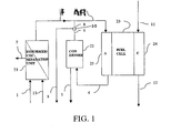
- Fig. 1 there may be seen a schematic representation of a power generation apparatus which generally comprises a fuel cell module 23, a reforming module 21 and a condenser unit 22.
- the fuel cell module 23 comprises a cathode compartment 24 with inlet 11 and outlet 12, and an anode compartment 25 with inlet 3 and outlet 4. Between the anode portion 25 and the cathode portion 24 is an electrolyte as is well known in the art.
- the reforming module 21 is provided with a fuel inlet 1 and a water inlet 13. Two outlets 2 and 7 are provided namely a hydrogen outlet 2 and a carbon dioxide outlet 7. The hydrogen outlet 2 from the reforming module 21 is fed to the anode inlet 3 of the fuel cell 23.
- the anode outlet 4 of the fuel cell 23 is fed to the condenser 22, provided with a water drain outlet 5 and a de-watered gas outlet 6.
- Flow from the condenser gas outlet 6 is divided into two channels 8 and 9 by a three-way valve 30. Flow from one of these channels 8 is fed back to the anode inlet 3.
- methane and water are fed into the reforming module 21 by means of inlets 1 and 13 respectively.
- the methane fuel is reformed into carbon dioxide and hydrogen as follows: CH 4 + H 2 O ⁇ 3H 2 + CO (reforming reaction) CO + H 2 O ⁇ H 2 + CO 2 (shift reaction)
- the hydrogen is separated from carbon dioxide by passing the resultant mixture thereof through a hydrogen permeable membrane which does not allow the carbon dioxide to pass.
- the hydrogen then exits the reforming module 21 via the hydrogen outlet 2 whilst the carbon dioxide exits through the other outlet 7 to be stored or reused.
- Hydrogen from the outlet 2 enters the anode inlet 3 of the fuel cell. Air is supplied to the cathode via the air inlet 11 and depleted air exits the cathode via the air outlet 12. Electrochemical reaction occurs in the fuel cell to provide an electrical current as is well known.
- the valve 30 may be used to determine what proportion of the hydrogen is recycled back to the fuel cell through pipe 8 and therefore how much is tapped off through pipe 9 for external use.
- Each mole of methane entering the system can free 8 electrons, either directly or indirectly when converted to 4 hydrogen molecules with two electrons each.
- the energy consumed is equal to the heat of formation of the methane entering the system.
- the power density is of significant importance, since the cost of the fuel cells is inversely proportional to the power density.
- the electrical efficiency has been improved from 57% to 85% and the power density increased from 504mW/cm2 to 728mW/cm2. This represents a substantial improvement.
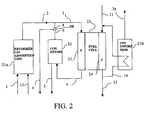
- FIG. 2 there may be seen a schematic representation of a power generation apparatus according to a second embodiment of the invention.
- the power generation apparatus represented in Fig. 2 differs from the apparatus illustrated in Fig. 1 in that instead of a hydrogen permeable membrane, the reforming module 21a is adapted to absorb carbon dioxide. This is subsequently desorbed in a desorption module 21b, which therefore has a carbon dioxide outlet 7a.
- the desorption module 21b includes a conduit 14 through it which is connected to the cathode inlet and outlets 11,12 respectively.
- the exhaust gas flow exiting the cathode at the outlet 12 may be routed via the conduit 14 through desorption module 21b back to cathode inlet 11. This allows the heat of the cathode exhaust gases to be used in the endothermic desorption reaction occurring in the desorption module 21b. Not only does this obviate the need to supply heat for the desorption module 21b, but it reduces the need to cool the fuel cell 23.
- the reforming reaction takes place as in the first embodiment: CH 4 + H 2 O ⁇ 3H 2 + CO (reforming reaction) CO + H 2 O ⁇ H 2 + CO 2 (shift reaction)
- Calcium oxide is then used to absorb the carbon dioxide to produce calcium carbonate: CaO + CO 2 ⁇ CaCO 3 (carbonation reaction) resulting in the following overall reaction: CH 4 + 2H 2 O + CaO ⁇ 4H 2 + CaCO 3 (integrated reforming & carbonation)
- the exothermic carbonation reaction is thermally coupled to the endothermic reforming reaction by virtue of both being carried out in the reforming module 21a.
- the equilibrium of the overall reaction gives 95+% (dry basis) hydrogen at standard (approximately 500°C) reforming temperatures.
- the exothermic electrochemical reaction is coupled to the endothermic calcination reaction such that the calcination reaction is almost complete at the high operating temperature of the SOFC.
- the reforming module is thermally integrated with the fuel cell (not illustrated). This is advantageous as the fuel cell provides the heat necessary for the endothermic reforming reaction.
- approximately 221kJ/mol is used for reforming, 174kJ/mol is released by the carbonation reaction, 38kJ/mol is released by the shift reaction, and a small amount of heat from the fuel cell is provided to the reforming module.
- Modules 21a and 21b may be separate, as illustrated, which requires the calcium oxide in the reforming module 21a and the calcium carbonate in the desorption module 21b to be replenished periodically. Alternatively, they may be linked, so that the metal carbonate produced by the reforming module 21a is desorbed by the desorption module 21b.
- Fig. 3 there may be seen a schematic representation of a power generation apparatus according to a third embodiment.
- the power generation apparatus represented in Fig. 3 differs from the apparatus illustrated in Fig. 2 in that the reforming module 21a is adapted to absorb carbon dioxide by reaction with a metal hydroxide as well as a metal oxide ("metal” is denoted below as "me").
- a water absorption unit 26 which does not have a water outlet, is used.
- the water may be absorbed by reaction with a metal oxide: meO + H 2 O ⁇ me(OH) 2
- Carbon dioxide may be desorbed by the usual process: meCO 3 ⁇ meO + CO 2
- this embodiment allows the recycling of reagents because the metal oxide produced in the desorption step may be used in the water absorption step. This produces metal hydroxide which may be used in the reforming and absorption reactions. This in turn produces metal carbonate which reacts to form metal oxide in the desorption step, thereby completing the cycle. This embodiment exhibits high efficiency and prolongs the life of the absorbent and desorbent.
- a dryer may be used to remove excess water.
- This dryer may take the form of a separate water desorption module, through which the hot cathode outflow is channelled (not illustrated).
Abstract
Description
- This invention relates to power generation apparatus containing fuel cells and particularly, but not exclusively, to apparatus which allow the coproduction of hydrogen as well as electricity.
- There is an ever increasing need to produce power as efficiently and cleanly as possible. Of particular concern is the discharge of carbon dioxide into the atmosphere. This is widely recognised to contribute to global warming and thus efforts are made to reduce carbon dioxide emissions into the atmosphere. One way of achieving this is of course to increase the efficiency with which power is generated from fuel. Another potential way of reducing carbon dioxide emissions into the atmosphere is to capture and store the carbon dioxide produced by the power generation process. This is problematic in conventional power generation systems based on combustion in air, however, since the carbon dioxide in the combustion products is mixed with a large amount of nitrogen. The presence of nitrogen makes the capture and separation of carbon dioxide significantly more expensive.
- In recent years there has been a lot of interest in fuel cells which are devices which are able to generate an electric current and heat directly from fuel without combustion. The direct generation of electric current means that the efficiency of such devices is not limited by thermodynamic efficiency limits. However, power generation systems based on fuel cells may still produce carbon dioxide.
- Most fuel cells operate on gaseous fuel, usually hydrogen (H2), methane (CH4) or carbon monoxide (CO), as well as oxygen (O2). A fuel cell comprises an anode and a cathode separated from each other by an electrolyte. Two types of electrochemical reactions occur: oxidation half-reaction(s) at the anode and reduction half-reaction(s) at the cathode. Typically, hydrogen (which may have been produced in situ from natural gas or other fuel in a process known as "reforming") undergoes electrochemical reaction at the anode, oxygen (which may be supplied in the form of air) undergoes electrochemical reaction at the cathode and the net reaction provides water and generates electrical power. Other components, such as methane or carbon monoxide, may also be present in the inflow to the fuel cell, particularly where the hydrogen is prepared by natural gas steam-reforming or coal gasification. This means that as well as water, there may be other products such as carbon dioxide.
- There are several types of fuel cell, some of which are described below.
- PEM (Polymer Electrolyte Membrane or Proton Exchange Membrane) cells operate at low temperatures (60-100°C). The electrolyte is a solid, flexible polymer. Hydrogen cations pass from the anode to the cathode. Platinum catalysts are used on both the cathode and anode. Water is produced at the cathode.
- PAFC (Phosphoric Acid Fuel Cells) operate at moderate temperatures (150-200°C). The electrolyte is a phosphoric acid matrix. Hydrogen cations pass from the anode to the cathode. Platinum catalysts are used on both the cathode and anode. A small amount of carbon monoxide in the hydrogen in-flow may be tolerated. Water is produced at the cathode. The reactions for both PEM fuel cells and PAFCs are:
- At anode:
2H2 → 4H+ + 4e-
- At cathode:
O2 + 4H+ + 4e- → 2H2O
- Net reaction:
2H2 + O2 → 2H2O
- MCFC (Molten Carbonate Fuel Cells) operate at high temperatures (600-1000°C). The electrolyte is a matrix of carbonates (e.g. Lithium, Sodium, Potassium and/or Magnesium carbonates). Carbonate anions pass from the cathode to the anode, and carbonate anions lost in this way are compensated for by supplying carbon dioxide to the cathode. Carbon monoxide may also be present in the hydrogen in-flow and used as fuel. Water is produced at the anode. The reactions are:
At anode:
2H2 + 2CO3 2- → 2H2O + 2CO2 + 4e-(also, if CO present : 2CO+2CO3 2- → 4CO2 + 4e-) At cathode:
O2 + 2CO2 + 4e- →2CO3 2-Net reaction:
2H2 + O2 → 2H2O(also, if CO present: 2CO + O2 → 2CO2) - SOFC (Solid Oxide Fuel Cells) also operate at high temperatures (600-1000°C). The electrolyte is a solid ceramic compound, e.g. zirconium oxides. Oxide ions pass from the cathode to the anode. Carbon monoxide may again be used as fuel. Water is produced at the anode. The reactions are:
At anode:
2H2 + 2O2- → 2H2O + 4e-(also, if CO present: 2CO + 2O2- → 2CO2 + 4e-) At cathode:
O2 + 4e- → 2O2-Net reaction:
2H2 + O2 → 2H2O(also, if CO present: 2CO + O2 → 2CO2) - The two most promising types of fuel cell are the Solid Oxide Fuel Cell (SOFC) typically operating at 600-1000 °C, and the Proton Exchange Membrane (PEM) fuel cell typically operating at 80°C.
- The SOFC may operate on most gaseous hydrocarbon fuels or fuels derived from the reforming of natural gas, diesel, gasoline or the gasification of solid fuels. When carbonaceous fuels are used, the product gases will contain carbon dioxide. In stationary applications the carbon dioxide may be captured and sequestrated, but this is more difficult to realise in mobile applications like cars. Furthermore, the PEM fuel cell most commonly used for mobile applications generally requires purified hydrogen for operation below 150°C.
- There remains a need for highly efficient and clean power and hydrogen generation systems to allow for a transition to a sustainable, low pollution use of fossil fuel energy without release of carbon dioxide to the atmosphere.
- The separation of carbon dioxide may be realised by different means. One possibility is to use membranes to separate the different species, another is to absorb gases in liquids or solids and desorb the gases separately using pressure swing or temperature swing cycles.
- Even though the efficiency of fuel cells is not limited thermodynamically, practically it has proven difficult to achieve efficiencies that approach the theoretical maximum. A number of hybrid systems have utilised the excess heat generated by an SOFC in a turbine or other machinery. However, these systems are complex, and the total efficiency is limited by the thermodynamic machinery.
- One proposal is disclosed in
US 5,079,103 . This document recognizes that hydrogen may be present in the gases exiting the anode of fuel cells such as MCFCs or SOFCs and, rather than using this for low-quality power generation (e.g. by combustion), seeks to separate it and carbon dioxide from the waste gas and utilize it more efficiently. The hydrogen may be separated from the waste gas by means of pressure swing absorption (PSA) and recycled back to the anode. The carbon dioxide may also be separated from the anode waste gas and, in the case of MCFCs, channelled to the cathode, thereby reducing the requirement for externally supplied carbon dioxide. The carbon dioxide may be separated from the anode waste gas by a scrubbing step or by PSA. - Thus, this document discloses that recycling the hydrogen and carbon dioxide in this way provides more energy than simply burning the anode waste gas. The document also discloses, as anode feed stream, natural gas which is internally reformed to hydrogen. Because natural gas is used, desulphurization may be required and recycling the hydrogen can assist with this. However, although this document claims overall efficiencies of up to 70%, this is still some way below the theoretical maximum. Furthermore, because carbon dioxide removal is carried out on the outflow from the fuel cell, large volumes of gas have to be cleaned.
-
US 2001/0010873 discloses an SOFC wherein a hydrocarbon-containing fuel is introduced to a fuel cell and converted therein to a synthesis gas (an endothermic reaction). The synthesis gas then undergoes partial electrochemical reaction (an exothermic reaction) thereby generating electricity. The hydrocarbon-containing fuel is supplied in such an excess that no additional cooling of the fuel cell is required, i.e. production of the synthesis gas is sufficiently endothermic to counter-balance the exothermic electrochemical reaction. This document teaches using natural gas to which water has been added as the hydrocarbon-containing fuel. The conversion of methane and water to hydrogen and carbon dioxide occurs within the fuel cell before the electrochemical reaction. The process ofUS 2001/0010873 suffers from several problems. Firstly, it does not satisfactorily address the problem of efficient use of fuel. Secondly, it does not provide an efficient process for separation of the exhaust material. Thirdly, in order to avoid coking, the amount of oxygen must be kept low and this limits the electrochemical potential. This results in below optimum performance with respect to electrical efficiency and power density. -
WO 02/15295 - "SOFC Efficiency at non standard conditions", Electrochemical Proceedings Volume 97-18, presents theoretical considerations for SOFC systems with high efficiency, and suggests the circulation of anode gas with condensation of water and recycling of hydrogen as a means for obtaining high efficiencies in hydrogen fuelled systems. Although improved electrical efficiencies may be realised by this theoretical concept, this can only be done by reducing the power density, since a very high cell potential is required. This paper does not disclose systems which exhibit both high efficiency and high power density.
-
US 2781248 ,BE 881637 - Whilst the use of anode gas recycling to improve the efficiency of a fuel cell system, and the use of calcium oxide/calcium carbonate cycles for the manufacture of hydrogen are known, there remains a need for improvements with respect to electrical efficiency, power density, carbon dioxide separation and parasitic losses.
-
WO 02/37590 claim 1. - Thus it will be seen that in accordance with the present invention hydrogen is produced and separated prior to entering the fuel cell. Separating the hydrogen before entering the fuel cell is advantageous because it allows an increase in the electrochemical potential (voltage) of the fuel. The presence of carbon dioxide or water reduces the voltage. Furthermore, separation prior to the fuel cell eases the processing and manipulation of the separated components.
- In the broadest aspect of the invention the hydrogen-containing stream fed from the reforming module to the anode may still contain some carbon dioxide. Preferably however it contains no more than 10 mol% of carbon dioxide, preferably no more than 5 mol% of carbon dioxide, more preferably no more than 1 mol% of carbon dioxide, more preferably no more than 0.1 mol% of carbon dioxide, most preferably no or substantially no carbon dioxide. This allows the voltage to be even higher, and makes the components even easier to process and manipulate as desired, compared to conventional systems. This is particularly useful where efficient separation and/or sequestration of carbon dioxide is desirable.
- Preferably the hydrogen-containing stream fed to the anode contains no or substantially no other components, apart from water. More preferably, no or substantially no water is present.
- References herein to water are intended to include water in any state, i.e. liquid, vapour etc.
- The other components from which the reforming module is arranged to separate hydrogen will depend upon the fuel used and the method of reforming. Suitable fuels include hydrocarbon fuels, particularly those requiring heat for their reforming reaction. Examples of suitable fuels are natural gas, methane, methanol, diesel, gasoline, coal, biomass, gases from the gasification of organic matter such as biomass or carbons/hydrocarbons, gases from the biological decomposition of organic matter such as biomass or carbons/hydrocarbons, and gas-hydrates. Any suitable method of reforming may be used; one suitable method is steam reforming.
- In the broadest aspect of the invention the hydrogen-containing stream fed from the reforming module to the anode may also contain some contaminants. Preferably however it contains at least 90% hydrogen, more preferably at least 95% hydrogen, more preferably at least 99% hydrogen, more preferably at least 99.9% hydrogen, where the percentages specified are mol %. Most preferably it contains no or substantially no other components apart from hydrogen. This further enhances the voltage and eases the processing and manipulation. This is because, in most types of fuel cell, where hydrogen is the only anode inflow, the only anode outflows will be hydrogen and, to the extent that electrochemical reaction has occurred, water.
- However, the presence of some nitrogen (for example, due to it being present in natural gas fuel) may be tolerated since this will not affect the voltage.
- Where water is present in the anode outflow it may be possible in accordance with the invention for it to remain at the final stage of processing. Preferably, however, means are provided for removing water from the anode outflow stream, for example a condenser or a water absorption unit may be used. This further allows an increase in the electrochemical potential (voltage) of the fuel and also makes the resultant stream easier to manipulate and utilise.
- Hydrogen produced at the output of the fuel cell in accordance with the invention may all be tapped off for use in a separate process. This has clear benefits since purified hydrogen is a valuable commodity in many applications. However the apparatus of the present invention is arranged to, or to be able to, recycle at least some hydrogen back to the inlet of the fuel cell.
- An increased level of efficiency is obtainable by recycling the hydrogen in the anode waste gas back to the anode, as is described hereinabove, whilst still allowing the possibility of some hydrogen being tapped off.
- The amount of hydrogen recycled back to the anode compared to the amount of hydrogen tapped off is variable. This means that the apparatus has a large degree of operational flexibility. The amount of hydrogen tapped off could, for example, be varied in a wide range between zero and all or substantially all of the hydrogen in the anode outflow, depending on particular requirements. For example the ratio of hydrogen recycled to hydrogen tapped off may be 100:0, 95:5, 90:10, 75:25, 50:50, 25:75, 10:90, 5:95 or 0:100.
- Conventional SOFC systems have significant shortcomings. In particular, where the cell voltage of a conventional SOFC is high, the fuel utilisation is reduced because the electrochemical potential of the fuel needs to be higher than the cell voltage, and only a fraction of the fuel can be used. Conversely, where the cell voltage of a conventional SOFC is low, the efficiency is low. In contrast, some preferred embodiments of the current invention allow high cell voltage, high efficiency and high fuel utilisation. Alternative preferred embodiments of the current invention allow low cell voltage, high efficiency (since in low cell voltage mode generated heat may be used for the production of hydrogen) and high fuel utilisation. In both types of embodiment the fuel utilisation is high because the fuel is fully utilised for the generation of electricity and/or hydrogen.
- In one possible mode of operation according to the invention, water is condensed from the anode exhaust stream, and all the hydrogen in the resultant stream is recycled back to the anode rather than tapped off.
- In another possible mode of operation according to the invention, water is condensed from the anode exhaust stream, and all the hydrogen in the resultant stream is tapped off rather than recycled back to the anode.
- In a further possible mode of operation according to the invention, water is condensed from the anode exhaust stream, some of the hydrogen in the resultant stream is tapped off and some of it is recycled back to the anode.
- The apparatus may allow flexibility both in the short term and in the long term. For example, if there is an immediate requirement for more purified hydrogen, the amount of hydrogen tapped off may be maximised simply by adjusting the means which direct the hydrogen to be tapped off rather than recycled. Adjustments can also be made to cope with differing loads on the power generation system. For example greater efficiency may be achieved at loads below the maximum by operating at a higher cell voltage at the expense of power density. This is achieved when the hydrogen recycling is controlled to achieve a high partial pressure of hydrogen at the anode. This latter scenario is discussed in more detail below and may be useful where the cost of fuel cells becomes less of a consideration in the future, so that lower power density (i.e. power per cell) is less problematic. It is worth noting, however, that the use of higher hydrogen/water ratios, or operation at higher cell voltages merely represents one of many ways of operating an apparatus in accordance with the invention. Enhanced efficiency may be achieved even when not operated in this way. For example it may be chosen to operate the apparatus in a mode which maximises power density (power produced per cell).
- Any known process can be used for reforming the hydrocarbon fuel. Similarly, any known process can be used for separating the thereby produced hydrogen from other components present following reforming.
- One method which is compatible with the current invention involves the reaction of methane with water. This produces hydrogen and carbon monoxide (a reforming reaction). The carbon monoxide then reacts with water to produce hydrogen and carbon dioxide (a shift reaction). The carbon dioxide can be separated or absorbed by any known method, e.g. in a scrubbing step, by pressure-swing absorption (for example using an amine), or by reaction with a further component. This allows the production of a separate stream of carbon dioxide, or disposal of carbon dioxide, for example by absorption into a disposable solid. For example, the carbon dioxide can be reacted with a metal oxide, for example a group II metal oxide, e.g. calcium oxide, to produce a metal carbonate (a carbonation reaction). In such a case, the overall reaction of reforming, shift and carbonation may be as follows:
CH4 + 2H2O + meO → 4H2 + meCO3
wherein me is a metal, e.g. calcium. The carbon dioxide may subsequently be released from the metal carbonate by heating it and this is known as a desorption reaction, or where the metal is calcium, a calcination reaction. - Absorption of carbon dioxide may also be achieved by reaction with a metal hydroxide, e.g. a group II metal hydroxide, e.g. calcium hydroxide.
- As noted above, carbon dioxide may be released from a metal carbonate in a desorption reaction. The apparatus of the current invention therefore comprises, in some preferred embodiments, a module which is adapted to allow desorption to take place.
- Where provided for, the carbonation and desorption reactions may occur in separate modules. For example, the reforming module may be adapted so that reforming, shift and carbonation occur therein to produce hydrogen and sequestered carbon dioxide (in the form of a metal carbonate), and there may be a separate desorption module adapted to release carbon dioxide from the metal carbonate. This has the advantage that metal oxide from the desorption module may be transferred to the reforming module, and metal carbonate from the reforming module may be transferred to the desorption module at an appropriate time. This reduces the need for a metal carbonate to be bought in. It also allows the production of carbon dioxide which is itself of value as a commodity, or as a component to be supplied to the cathode of MCFC fuel cells. Of course, these advantages are supplementary to the major environmental advantages of carbon dioxide separation according to the invention.
- In a further embodiment, the reforming modules and the desorption module may be linked, so that the metal carbonate produced by the former is desorbed by the latter. This is desirable in terms of efficiency and ease of use.
- According to a further embodiment means are provided for switching flow to the reforming module to the desorption module and/or for switching flow to the desorption module to the reforming module. In this way the reforming module may also function as a desorption module and/or the desorption module may also function as a reforming module. For example, the flows to the reforming module and desorption module may be switched for appropriate time periods. This allows, for example, the carbon dioxide absorbed in the reforming module during reforming to be subsequently released by channelling the cathode outflow through the reforming module and/or the carbon dioxide released from the desorption module to be subsequently replaced by channelling the fuel input through the desorption module. Other advantages of this system include the ease of re-utilisation of the carbon dioxide absorbent.
- Other possible alternatives for separating the hydrogen produced in the reformer from the other components present include the use of a hydrogen permeable membrane.
- In the broadest scope of the invention the reforming module and the fuel cell may be entirely separate from one another save for the provision of hydrogen from the former to the latter. More preferably though the reforming module is thermally integrated with the fuel cell. This results in the net exothermic nature of the electrochemical reactions being at least partially balanced with the net endothermic nature of the non-electrochemical reactions which occur in the reforming module. The integration may be achieved through a close physical proximity between the elements or through heat transfer means which could comprise a solid, liquid or gas transfer medium.
- Similarly, where there is a separate desorption module as described previously it is preferably thermally integrated with the fuel cell. This results in the net exothermic nature of the electrochemical reactions being at least partially balanced with the net endothermic nature of the non-electrochemical reactions which occur in the desorption module. Again physical proximity or a transfer medium may be used.
- Preferably, therefore, the reforming module, the fuel cell and the desorption module are thermally integrated with each other, most preferably by heat transfer means between the fuel cell and reforming module, and heat transfer means between the fuel cell and desorption module. In a further envisaged embodiment, there are also heat transfer means between the reforming module and the desorption module.
- In one preferred example, the heat transfer means comprise heat transfer loops, e.g. loops which route the cathode exhaust via the reforming and/or desorption module, loops which route the anode exhaust via the reforming and/or desorption module. This is particularly useful for utilising the high temperature "waste" heat of SOFC systems. Where the anode or cathode exhausts are routed in this way, in one embodiment the exhaust components are physically separated from the reforming and/or desorption modules, thereby interacting only in a thermal, as opposed to a chemical, manner. In another embodiment, where the heat transfer loop is an anode exhaust loop, the exhaust components are simply fed into the reforming module such that they can interact chemically as well as thermally in the reforming module. Thus, for example, the water required for the reforming reaction is preferably taken directly or indirectly from the anode exhaust loop.
- As noted above, the anode exhaust may be recycled back to the anode. The same applies to the cathode exhaust which may be recycled back to the cathode via the reforming and/or desorption modules. Such cathode flow recycling aids the removal of excess heat from the fuel cell. The amount of cathode flow required to remove the heat would normally be greater than the amount of flow required for the electrochemical reaction. However, this allows the air to be cycled several times, thereby reducing the need for air from the outside and reducing the amount of air emitted. In one example, the heated cathode exhaust is cooled by about 50 to 200°C in the calcination reactor and recycled to the stack where it is heated by about 50 to 200°C before continuing around the loop, a fraction of the air in the cathode loop being replaced for the electrochemical reaction.
- Efficient heat transfer in this way has the result that neither the cooling effect of the non-electrochemical reactions, nor the heating effect of the electrochemical reactions, are wasted. Where the electrochemical reactions are more exothermic than the non-electrochemical reactions are net endothermic, preferably substantially all the cooling energy of the latter are used to cool the electrochemical reactions. Conversely, where the electrochemical reactions are less exothermic than the non-electrochemical reactions are net endothermic, preferably substantially all the energy of the former are used to drive the non-electrochemical reactions.
- In this way the preferred embodiment of the invention can provide a power generation system which has an electrical efficiency close to the theoretical, non-thermodynamic, maximum, limited only by small thermal and pressure losses. At the same time, the carbon dioxide separation process can be thermally integrated with the power generation process.
- In a further preferred embodiment, reactions which occur in the reforming module (e.g. reforming, shift and carbonation) are themselves thermally integrated with each other, either by virtue of these reactions occurring in close vicinity to each other, or by using additional heat transfer means where necessary. This further enhances the efficiency of the apparatus.
- The flexibility of the power generation apparatus has been discussed above. This flexibility allows the apparatus to be operated in accordance with further aspects of the invention.
- As technology progresses, the unit cost of fuel cells is reducing and in such modes of operation the current invention seeks in part to take advantage of this. Conventionally, fuel cells are operated at a cell voltage of about 0.7 volts. Operation at a higher cell voltage has hitherto been avoided because this has been associated with a lower power density, i.e. less power produced per fuel cell. The electrical load which may be drawn from the fuel cell exhibits an inverse relationship with the cell voltage.
- In contrast, the applicant has appreciated that a lower degree of fuel utilization per cycle, although associated with a lower power density (power produced per cell), allows operation at a higher cell voltage and this in turn gives greater efficiency. Whilst this necessitates provision of more fuel cells, it means that the fuel is used more efficiently to produce power.
- Accordingly, a preferred method of operating the apparatus of the invention comprises recycling hydrogen from the anode outflow back to the anode inlet, such that the fuel cell has a cell operating voltage of at least 0.8 volts.
- In accordance with this method therefore, it is feasible to construct a power generation system which is not designed to operate normally at its full capacity without suffering any significant loss in efficiency, It allows however for surges in demand for power to be met, again without significant loss of efficiency. This is a much more practically useful prospect than a system which only achieves its peak efficiency at full load - since in practice a generator is unlikely to be operated at full load for most of the time.
- The method also comprises reforming hydrocarbon fuel to hydrogen and other components, and separating said hydrogen from said other components, in a separate reforming module, and feeding said hydrogen from said reforming module to the anode of the fuel cell.
- Preferably the minimum operating cell voltage is between 0.8 volts and 0.9 volts, more preferably between 0.82 volts and 0.87 volts, most preferably approximately 0.85 volts. This is the voltage that is found to be most effective and practical for efficient fuel utilisation. The actual voltage will depend on specific demands of electricity and hydrogen, and will vary depending on the specific application.
- The cell voltage and partial pressure of hydrogen flowing through the anode and recycled are of course related. Therefore, a further preferred method of operating the apparatus of the invention comprises recycling hydrogen from the anode outflow back to the anode inlet, such that the molar ratio of hydrogen to water in the anode outflow is greater than 0.5, more preferably greater than 1.0, more preferably greater than 10, more preferably greater than 25, more preferably greater than 40.
- The applicant has appreciated that operating the apparatus at a high cell voltage and/or a high partial pressure of hydrogen at the anode is desirable in certain circumstances.
- According to the Nernst equation, the fuel cell potential at the outlet is reduced from the theoretical maximum voltage by an amount that depends on the relative amounts of reactants and products. As the ratio of hydrogen to water increases, a greater fuel cell potential will be possible and the cell will be able to operate at a higher cell voltage.
- The fuel cell may be a PEM fuel cell, but is preferably a PAFC fuel cell, or a high temperature fuel cell, most preferably a molten carbonate fuel cell or solid oxide fuel cell (MCFC or SOFC). These fuel cells are energy efficient in combination with the improvements of the current invention and the SOFC system is the most suited to the current invention.
- Certain preferred embodiments of the invention will now be described, by way of example only, with reference to the accompanying schematic drawings in which:
-
Fig. 1 shows schematically an embodiment of a power generation system in accordance with the present invention; -
Fig. 2 shows schematically a second embodiment of a power generation system in accordance with the present invention; and -
Fig. 3 shows schematically a third embodiment of a power generation system in accordance with the present invention. - Turning firstly to
Fig. 1 , there may be seen a schematic representation of a power generation apparatus which generally comprises afuel cell module 23, a reformingmodule 21 and acondenser unit 22. - The
fuel cell module 23 comprises acathode compartment 24 withinlet 11 andoutlet 12, and ananode compartment 25 withinlet 3 andoutlet 4. Between theanode portion 25 and thecathode portion 24 is an electrolyte as is well known in the art. - The reforming
module 21 is provided with afuel inlet 1 and awater inlet 13. Twooutlets hydrogen outlet 2 and acarbon dioxide outlet 7. Thehydrogen outlet 2 from the reformingmodule 21 is fed to theanode inlet 3 of thefuel cell 23. - The
anode outlet 4 of thefuel cell 23 is fed to thecondenser 22, provided with awater drain outlet 5 and ade-watered gas outlet 6. Flow from thecondenser gas outlet 6 is divided into twochannels way valve 30. Flow from one of thesechannels 8 is fed back to theanode inlet 3. - In operation, methane and water are fed into the reforming
module 21 by means ofinlets module 21, the methane fuel is reformed into carbon dioxide and hydrogen as follows:
CH4 + H2O → 3H2 + CO (reforming reaction)
CO + H2O → H2 + CO2 (shift reaction)
- It will of course be appreciated that the chemical equations discussed in the present application relate to equilibria and that the equilibrium positions will not necessarily be completely to the right-hand (product) side of the equations. For example, the above two reactions may occur only to a partial extent.
- The hydrogen is separated from carbon dioxide by passing the resultant mixture thereof through a hydrogen permeable membrane which does not allow the carbon dioxide to pass. The hydrogen then exits the reforming
module 21 via thehydrogen outlet 2 whilst the carbon dioxide exits through theother outlet 7 to be stored or reused. - Hydrogen from the
outlet 2 enters theanode inlet 3 of the fuel cell. Air is supplied to the cathode via theair inlet 11 and depleted air exits the cathode via theair outlet 12. Electrochemical reaction occurs in the fuel cell to provide an electrical current as is well known. - Water and unreacted hydrogen exit the
anode outlet 4 to be fed into thecondenser 22. Condensed water leaves thecondenser 22 via the drain outlet 5 (which may be used to replenish the supply to the reformer inlet 13). The dewatered hydrogen exits through the other outlet to the three-way valve 30. Thevalve 30 may be used to determine what proportion of the hydrogen is recycled back to the fuel cell throughpipe 8 and therefore how much is tapped off throughpipe 9 for external use. - The high electrical efficiency and high total efficiency as well as the flexibility with respect to operating flexibility will be demonstrated by the following Example. For comparison, efficiency and power density calculations are first performed for a conventional state of the art SOFC system. A specific cell resistance of Rc=0.25 ohm*cm2 and a fuel feed of Ff=1.25 mole/second of methane equivalent to 1 MJ/s are assumed for all the systems.
- A conventional SOFC system is typically operated under the conditions shown below:
Cell voltage Uc=0.7 V Operating temperature 1000C Fuel utilisation Fu=85% Water:hydrogen ratio at inlet
(minimum required to avoid soot formation)1:9 Electrochemical potential at fuel cell inlet Ui=1.00V Electrochemical potential at fuel cell outlet Uo=0.76V - Each mole of methane entering the system can free 8 electrons, either directly or indirectly when converted to 4 hydrogen molecules with two electrons each.
- Considering also the fuel utilisation, the electrical output of the fuel cell will be

Where F = Faradays constant = 96487 coulomb/mole - The electrical efficiency is given by

- The energy consumed is equal to the heat of formation of the methane entering the system. The heat of formation (lower heating value) of methane is LHV_CH4= 802kJ/mole, and the assumed feed rate is 1.25 mole/s.
- With the given values:

- The average electrochemical potential over the cell is Ua=0.5*(Ui+Uo), with the given values

- The average power density of the cell will be
Wa = (Ua-Uc)*Uc/Rc, with the given values
Wa = (0.88V-0.7V)*0.7V/0.25ohm*cm2=504mW/cm2 - The power density is of significant importance, since the cost of the fuel cells is inversely proportional to the power density.
- A system corresponding to that shown schematically in
Fig. 1 is operated under the conditions shown below:Fuel feed at fuel inlet 1: Ff=1.25 mole/s of methane Cell voltage 0.7 V Operating temperature 1000C Water:hydrogen ratio at inlet (humidified hydrogen, zero carbon content prohibits soot formation) 3:97 Electrochemical potential at fuel cell inlet Ui=1.07V Electrochemical potential at fuel cell outlet Uo=0.85V - In this example, half of the hydrogen entering the fuel cell anode chamber is converted electrochemically, while the other half leaves the system as produced hydrogen. Each mole of methane is converted to 4 moles of hydrogen in the reformer, hence hydrogen is produced at a rate of 2.5 mole/s and converted electrochemically at a rate of 2.5 mole/s. The net chemical energy consumed in the system is then given by the difference in heating value of the methane fuel stream entering the system and the produced hydrogen fuel stream leaving the system. The heat of formation (lower heating value) of methane is LHV_CH4= 802kJ/mole, the heat of formation (lower heating value) of hydrogen is LHV_H2= 242kJ/mole and the assumed feed rate is 1.25 mole/s.

Electric output = 2*F*Uc*hydrogen converted - The electrical efficiency is given by
- Electrical efficiency= Electrical output/Energy consumed With the given values:

- The average electrochemical potential over the cell is
Ua = 0.5*(Ui+Uo), with the given values
- The average power density of the cell will be
Wa = (Ua-Uc)*Uc/Rc, with the given values
- Compared to the conventional system, the electrical efficiency has been improved from 57% to 85% and the power density increased from 504mW/cm2 to 728mW/cm2. This represents a substantial improvement.
- In
Fig. 2 , there may be seen a schematic representation of a power generation apparatus according to a second embodiment of the invention. - The power generation apparatus represented in
Fig. 2 differs from the apparatus illustrated inFig. 1 in that instead of a hydrogen permeable membrane, the reformingmodule 21a is adapted to absorb carbon dioxide. This is subsequently desorbed in adesorption module 21b, which therefore has acarbon dioxide outlet 7a. - The
desorption module 21b includes aconduit 14 through it which is connected to the cathode inlet andoutlets outlet 12 may be routed via theconduit 14 throughdesorption module 21b back tocathode inlet 11. This allows the heat of the cathode exhaust gases to be used in the endothermic desorption reaction occurring in thedesorption module 21b. Not only does this obviate the need to supply heat for thedesorption module 21b, but it reduces the need to cool thefuel cell 23. - It will be appreciated that whilst recycling of the cathode gases via the
conduit 14 is shown, this is not essential in order to be able to realise the thermal integration set out above. - The reforming reaction takes place as in the first embodiment:
CH4 + H2O → 3H2 + CO (reforming reaction)
CO + H2O → H2 + CO2 (shift reaction)
- Calcium oxide is then used to absorb the carbon dioxide to produce calcium carbonate:
CaO + CO2 → CaCO3 (carbonation reaction)
resulting in the following overall reaction:
CH4 + 2H2O + CaO → 4H2 + CaCO3
(integrated reforming & carbonation) - Utilizing heat from the
fuel cell 23 via theconduit 14, carbon dioxide is then desorbed from the carbonate according to
CaCO3 + heat → CO + CO2 (desorption reaction)
and the calcium oxide is then recycled in the process. The desorption reaction is referred to as a calcination reaction. - In this embodiment, the exothermic carbonation reaction is thermally coupled to the endothermic reforming reaction by virtue of both being carried out in the reforming
module 21a. The equilibrium of the overall reaction (integrated reforming and calcination) gives 95+% (dry basis) hydrogen at standard (approximately 500°C) reforming temperatures. The exothermic electrochemical reaction is coupled to the endothermic calcination reaction such that the calcination reaction is almost complete at the high operating temperature of the SOFC. - The reforming module is thermally integrated with the fuel cell (not illustrated). This is advantageous as the fuel cell provides the heat necessary for the endothermic reforming reaction. In one example of an integrated reforming/carbonation reactor, approximately 221kJ/mol is used for reforming, 174kJ/mol is released by the carbonation reaction, 38kJ/mol is released by the shift reaction, and a small amount of heat from the fuel cell is provided to the reforming module.
- The above processes allow a particularly efficient carbon dioxide absorption and desorption process in accordance with the principles of the present invention.
-
Modules module 21a and the calcium carbonate in thedesorption module 21b to be replenished periodically. Alternatively, they may be linked, so that the metal carbonate produced by the reformingmodule 21a is desorbed by thedesorption module 21b. - The use of calcium is only illustrative and other metals may be appropriate instead.
- In
Fig. 3 , there may be seen a schematic representation of a power generation apparatus according to a third embodiment. The power generation apparatus represented inFig. 3 differs from the apparatus illustrated inFig. 2 in that the reformingmodule 21a is adapted to absorb carbon dioxide by reaction with a metal hydroxide as well as a metal oxide ("metal" is denoted below as "me"). In addition, rather than using a condenser in the hydrogen recycle loop, awater absorption unit 26, which does not have a water outlet, is used. - In this embodiment the reforming and carbon dioxide absorption reactions are as follows.
me (OH)2 + CH4 → meO + CO + 3H2
CO + me (OH)2 → H2 + meCO3
- The water may be absorbed by reaction with a metal oxide:
meO + H2O →me(OH)2
- Carbon dioxide may be desorbed by the usual process:
meCO3 → meO + CO2
- Accordingly, this embodiment allows the recycling of reagents because the metal oxide produced in the desorption step may be used in the water absorption step. This produces metal hydroxide which may be used in the reforming and absorption reactions. This in turn produces metal carbonate which reacts to form metal oxide in the desorption step, thereby completing the cycle. This embodiment exhibits high efficiency and prolongs the life of the absorbent and desorbent.
- Whilst this embodiment does not require a steamer or condenser, a dryer may be used to remove excess water. This dryer may take the form of a separate water desorption module, through which the hot cathode outflow is channelled (not illustrated).
Claims (10)
- A power generation apparatus comprising a fuel cell (23) and a reforming module (21), wherein the reforming module is adapted to reform hydrocarbon fuel into hydrogen and other components, and to separate said hydrogen from said other components, the apparatus being arranged so that said hydrogen is fed from the reforming module to the anode (3) of the fuel cell; the apparatus also comprising means for recycling hydrogen (8) in the outflow stream of the anode (4) of the fuel cell back to the anode, characterised in that the apparatus comprises control means (30) controlling the porportion of hydrogen recycled during operation to meet external hydrogen or differing electrical load requirements" and means (9) for tapping off for external use hydrogen from the outflow stream of the anode that is not recycled.
- Apparatus as claimed in claim 1, wherein the apparatus is arranged such that substantially nothing except hydrogen is fed to the fuel cell (23).
- Apparatus as claimed in claim 1 or 2, comprising means for removing water from the outflow stream of the anode (4) of the fuel cell (23).
- Apparatus as claimed in any preceding claim,
wherein the reforming module (21) comprises means for separating carbon dioxide and means (7) for ouputting a stream of said carbon dioxide. - Apparatus as claimed in any of claims 1 to 3,
wherein the reforming module (21) comprises means for absorbing carbon dioxide or sequestering it into a solid. - Apparatus as claimed in claim 1, wherein the reforming module (21) comprises means for absorbing the carbon dioxide by a carbonation reaction with a metal oxide or hydroxide to produce a metal carbonate.
- Apparatus as claimed in any preceding claim which also comprises a desorption module (21b) adapted to allow the release of carbon dioxide.
- Apparatus as claimed in any preceding claim,
wherein the reforming module (21) is thermally integrated with the fuel cell (23). - Apparatus as claimed in claim 7 or 8, wherein the desorption module (21b) is thermally integrated with the fuel cell.
- A method of generating power and producing hydrogen using an apparatus as claimed in any of claims 1 to 9.
Applications Claiming Priority (3)
| Application Number | Priority Date | Filing Date | Title |
|---|---|---|---|
| GBGB0221304.9A GB0221304D0 (en) | 2002-09-13 | 2002-09-13 | Co-production of hydrogen |
| GB0221304 | 2002-09-13 | ||
| PCT/GB2003/003969 WO2004025767A2 (en) | 2002-09-13 | 2003-09-15 | Power generation apparatus |
Publications (2)
| Publication Number | Publication Date |
|---|---|
| EP1540760A2 EP1540760A2 (en) | 2005-06-15 |
| EP1540760B1 true EP1540760B1 (en) | 2011-07-13 |
Family
ID=9944038
Family Applications (1)
| Application Number | Title | Priority Date | Filing Date |
|---|---|---|---|
| EP03795093A Expired - Lifetime EP1540760B1 (en) | 2002-09-13 | 2003-09-15 | Power generation apparatus |
Country Status (9)
| Country | Link |
|---|---|
| US (2) | US20060127714A1 (en) |
| EP (1) | EP1540760B1 (en) |
| AT (1) | ATE516605T1 (en) |
| AU (1) | AU2003264762A1 (en) |
| DK (1) | DK1540760T3 (en) |
| ES (1) | ES2368418T3 (en) |
| GB (1) | GB0221304D0 (en) |
| PT (1) | PT1540760E (en) |
| WO (1) | WO2004025767A2 (en) |
Families Citing this family (28)
| Publication number | Priority date | Publication date | Assignee | Title |
|---|---|---|---|---|
| US7878280B2 (en) | 2003-04-09 | 2011-02-01 | Bloom Energy Corporation | Low pressure hydrogen fueled vehicle and method of operating same |
| US7575822B2 (en) | 2003-04-09 | 2009-08-18 | Bloom Energy Corporation | Method of optimizing operating efficiency of fuel cells |
| US7364810B2 (en) | 2003-09-03 | 2008-04-29 | Bloom Energy Corporation | Combined energy storage and fuel generation with reversible fuel cells |
| US7482078B2 (en) * | 2003-04-09 | 2009-01-27 | Bloom Energy Corporation | Co-production of hydrogen and electricity in a high temperature electrochemical system |
| DE10356012A1 (en) * | 2003-11-27 | 2005-06-30 | Airbus Deutschland Gmbh | Arrangement and method for producing water on board an aircraft |
| FR2870389A1 (en) * | 2004-05-11 | 2005-11-18 | Renault Sas | Hydrogen feeding device for fuel cell, has palladium and/or polymer based membrane enriching flow of hydrogen from anode of cell to increase concentration of flow and to feed anode by mixing hydrogen enriched flow with flow from reformer |
| US7635531B1 (en) * | 2005-08-18 | 2009-12-22 | The United States Of America As Represented By The Secretary Of The Navy | Self contained fuel system for solid oxide fuel cell |
| US8273487B2 (en) * | 2006-09-19 | 2012-09-25 | Bloom Energy Corporation | Fuel cell system with fuel distillation unit |
| US8057945B2 (en) * | 2007-10-24 | 2011-11-15 | Atomic Energy Council-Institute Of Nuclear Energy Research | Solid oxide fuel cell with recycled core outlet products |
| EP2220717A1 (en) * | 2007-12-17 | 2010-08-25 | Shell Internationale Research Maatschappij B.V. | Fuel cell-based system for generating electrical power |
| WO2009079429A1 (en) * | 2007-12-17 | 2009-06-25 | Shell Oil Company | System and process for generating electrical power |
| TW200937721A (en) * | 2007-12-17 | 2009-09-01 | Shell Int Research | System and process for generating electrical power |
| US20090155650A1 (en) * | 2007-12-17 | 2009-06-18 | Jingyu Cui | System and process for generating electrical power |
| US20090155638A1 (en) * | 2007-12-17 | 2009-06-18 | Jingyu Cui | System and process for generating electrical power |
| US20090155639A1 (en) * | 2007-12-17 | 2009-06-18 | Jingyu Cui | System and process for generating electrical power |
| WO2009079434A1 (en) * | 2007-12-17 | 2009-06-25 | Shell Oil Company | Fuel cell-based process for generating electrical power |
| AU2008338507A1 (en) * | 2007-12-17 | 2009-06-25 | Shell Internationale Research Maatschappij B.V. | System and process for generating electrical power |
| AU2008338499A1 (en) * | 2007-12-17 | 2009-06-25 | Shell Internationale Research Maatschappij B.V. | Fuel cell-based process for generating electrical power |
| AU2009215686B2 (en) | 2008-02-18 | 2012-03-15 | Shell Internationale Research Maatschappij B.V. | Process for the conversion of ethane to aromatic hydrocarbons |
| MY156207A (en) | 2008-02-18 | 2016-01-29 | Shell Int Research | Process for the conversion of ethane to aromatic hydrocarbons |
| CN101945702B (en) | 2008-02-20 | 2014-05-28 | 国际壳牌研究有限公司 | Process for the conversion of ethane to aromatic hydrocarbons |
| US8500868B2 (en) * | 2009-05-01 | 2013-08-06 | Massachusetts Institute Of Technology | Systems and methods for the separation of carbon dioxide and water |
| US8563186B2 (en) * | 2009-06-16 | 2013-10-22 | Shell Oil Company | Systems and processes of operating fuel cell systems |
| NO332984B1 (en) * | 2009-12-22 | 2013-02-11 | Zeg Power As | Method and device for simultaneous production of energy in the form of electricity, heat and hydrogen gas |
| KR101277123B1 (en) * | 2012-09-07 | 2013-06-20 | 한국기초과학지원연구원 | Plasma dry reforming apparatus |
| NO343140B1 (en) | 2013-06-14 | 2018-11-19 | Zeg Power As | Process for sustainable energy production in a power plant comprising a solid oxide fuel cell |
| NO345296B1 (en) | 2016-07-14 | 2020-11-30 | Zeg Power As | Method and power plant comprising a Solid Oxide Fuel Cell (SOFC) for production of electrical energy and H2 gas |
| CN109004244A (en) * | 2018-07-09 | 2018-12-14 | 中国石油大学(北京) | Solid oxide fuel cell association system based on solar energy preparing hydrogen by reforming methanol |
Citations (1)
| Publication number | Priority date | Publication date | Assignee | Title |
|---|---|---|---|---|
| US5079103A (en) * | 1989-04-25 | 1992-01-07 | Linde Aktiengesellschaft | Fuel cells with hydrogen recycle |
Family Cites Families (20)
| Publication number | Priority date | Publication date | Assignee | Title |
|---|---|---|---|---|
| US2781248A (en) * | 1953-01-06 | 1957-02-12 | Consolidation Coal Co | Manufacture of hydrogen |
| BE881637A (en) | 1980-02-08 | 1980-05-30 | Rutgers Arend J | ALTERNATIVE PRODUCTION OF HYDROGEN |
| WO2000016423A2 (en) * | 1998-09-14 | 2000-03-23 | Forschungszentrum Jülich GmbH | Solid oxide fuel cell which operates with an excess of fuel |
| DE19908905C2 (en) * | 1999-03-02 | 2003-03-20 | Daimler Chrysler Ag | Fuel cell system with associated hydrogen production plant |
| NL1013474C2 (en) * | 1999-05-27 | 2000-12-01 | Plug Power Inc | System for generating electrical energy and heat. |
| US6280865B1 (en) * | 1999-09-24 | 2001-08-28 | Plug Power Inc. | Fuel cell system with hydrogen purification subsystem |
| US6790430B1 (en) * | 1999-12-09 | 2004-09-14 | The Regents Of The University Of California | Hydrogen production from carbonaceous material |
| JP4575551B2 (en) * | 2000-05-30 | 2010-11-04 | 本田技研工業株式会社 | Gas supply device for fuel cell |
| US6541141B1 (en) | 2000-06-13 | 2003-04-01 | Hydrogenics Corporation | Water recovery in the anode side of a proton exchange membrane fuel cell |
| US6610434B1 (en) | 2000-08-10 | 2003-08-26 | Siemens Westinghouse Power Corporation | Segregated exhaust SOFC generator with high fuel utilization capability |
| JP3607862B2 (en) * | 2000-09-29 | 2005-01-05 | 株式会社日立製作所 | Fuel cell |
| WO2002035623A2 (en) * | 2000-10-27 | 2002-05-02 | Questair Technologies Inc. | Systems and processes for providing hydrogen to fuel cells |
| US7097925B2 (en) * | 2000-10-30 | 2006-08-29 | Questair Technologies Inc. | High temperature fuel cell power plant |
| AU780651B2 (en) * | 2000-10-30 | 2005-04-07 | Questair Technologies, Inc. | Energy efficient gas separation for fuel cells |
| CA2325072A1 (en) * | 2000-10-30 | 2002-04-30 | Questair Technologies Inc. | Gas separation for molten carbonate fuel cell |
| US20020122969A1 (en) * | 2000-12-15 | 2002-09-05 | Manfred Herrmann | Pressure driven hermetically sealed pump for fuel cell system |
| US20020085967A1 (en) * | 2000-12-18 | 2002-07-04 | Kabushiki Kaisha Toyota Chuo Kenkyusho | Process for generating hydrogen and apparatus for generating hydrogen |
| US20020136939A1 (en) * | 2001-02-15 | 2002-09-26 | Grieve M. James | Fuel cell and battery voltage controlling method and system |
| AU2002243456A1 (en) * | 2002-01-04 | 2003-07-30 | International Fuel Cells, Llc | Procedure for starting up a fuel cell system having an anode exhaust recycle loop |
| US6777119B2 (en) * | 2002-03-12 | 2004-08-17 | Utc Fuel Cells, Llc | Actively-cooled water recovery in fuel cell power plants |
-
2002
- 2002-09-13 GB GBGB0221304.9A patent/GB0221304D0/en not_active Ceased
-
2003
- 2003-09-15 WO PCT/GB2003/003969 patent/WO2004025767A2/en not_active Application Discontinuation
- 2003-09-15 DK DK03795093.8T patent/DK1540760T3/en active
- 2003-09-15 ES ES03795093T patent/ES2368418T3/en not_active Expired - Lifetime
- 2003-09-15 US US10/527,971 patent/US20060127714A1/en not_active Abandoned
- 2003-09-15 EP EP03795093A patent/EP1540760B1/en not_active Expired - Lifetime
- 2003-09-15 AU AU2003264762A patent/AU2003264762A1/en not_active Abandoned
- 2003-09-15 AT AT03795093T patent/ATE516605T1/en active
- 2003-09-15 PT PT03795093T patent/PT1540760E/en unknown
-
2011
- 2011-06-14 US US13/160,164 patent/US9373856B2/en not_active Expired - Lifetime
Patent Citations (1)
| Publication number | Priority date | Publication date | Assignee | Title |
|---|---|---|---|---|
| US5079103A (en) * | 1989-04-25 | 1992-01-07 | Linde Aktiengesellschaft | Fuel cells with hydrogen recycle |
Also Published As
| Publication number | Publication date |
|---|---|
| GB0221304D0 (en) | 2002-10-23 |
| WO2004025767A3 (en) | 2004-07-29 |
| AU2003264762A1 (en) | 2004-04-30 |
| PT1540760E (en) | 2011-09-01 |
| ATE516605T1 (en) | 2011-07-15 |
| WO2004025767A2 (en) | 2004-03-25 |
| DK1540760T3 (en) | 2011-10-03 |
| US9373856B2 (en) | 2016-06-21 |
| US20060127714A1 (en) | 2006-06-15 |
| EP1540760A2 (en) | 2005-06-15 |
| ES2368418T3 (en) | 2011-11-17 |
| US20110244341A1 (en) | 2011-10-06 |
Similar Documents
| Publication | Publication Date | Title |
|---|---|---|
| US9373856B2 (en) | Method of recycling and tapping off hydrogen for power generation apparatus | |
| US20210091398A1 (en) | Reformer-electrolyzer-purifier (rep) assembly for hydrogen production, systems incorporating same and method of producing hydrogen | |
| JP5331819B2 (en) | MCFC power generation system | |
| US6623880B1 (en) | Fuel cell-fuel cell hybrid system | |
| JP5405486B2 (en) | Fuel cell system | |
| KR100762685B1 (en) | reformer and fuel cell system using the same | |
| US20050112425A1 (en) | Fuel cell for hydrogen production, electricity generation and co-production | |
| US20050123810A1 (en) | System and method for co-production of hydrogen and electrical energy | |
| EP1241723B1 (en) | Water recovery for a fuel cell system | |
| JP2011508949A5 (en) | ||
| CN108604695B (en) | Energy storage with engine REP | |
| JP6639578B2 (en) | Hydrogen and carbon monoxide production using REP with partial oxidation | |
| JP2013258004A (en) | High-temperature fuel cell system | |
| JP7364831B2 (en) | Power generation system using cascaded fuel cells and related methods | |
| JP2007141772A (en) | Fuel cell system | |
| US11309563B2 (en) | High efficiency fuel cell system with hydrogen and syngas export | |
| US10283793B2 (en) | Combined generation system and method for collecting carbon dioxide for combined generation system | |
| KR102439950B1 (en) | Ammonia based complex fuel cell system | |
| JP2007128786A (en) | Fuel cell system | |
| JP2004171802A (en) | Fuel cell system | |
| JP2009117170A (en) | Hydrogen and power generating system, and load following power generation method therein | |
| JP2003109638A (en) | Sofc fuel recycle system | |
| KR102252149B1 (en) | Ship | |
| JP2009093893A (en) | Fuel cell system |
Legal Events
| Date | Code | Title | Description |
|---|---|---|---|
| PUAI | Public reference made under article 153(3) epc to a published international application that has entered the european phase |
Free format text: ORIGINAL CODE: 0009012 |
|
| 17P | Request for examination filed |
Effective date: 20050413 |
|
| AK | Designated contracting states |
Kind code of ref document: A2 Designated state(s): AT BE BG CH CY CZ DE DK EE ES FI FR GB GR HU IE IT LI LU MC NL PT RO SE SI SK TR |
|
| AX | Request for extension of the european patent |
Extension state: AL LT LV MK |
|
| DAX | Request for extension of the european patent (deleted) | ||
| 17Q | First examination report despatched |
Effective date: 20061128 |
|
| GRAP | Despatch of communication of intention to grant a patent |
Free format text: ORIGINAL CODE: EPIDOSNIGR1 |
|
| GRAS | Grant fee paid |
Free format text: ORIGINAL CODE: EPIDOSNIGR3 |
|
| GRAA | (expected) grant |
Free format text: ORIGINAL CODE: 0009210 |
|
| AK | Designated contracting states |
Kind code of ref document: B1 Designated state(s): AT BE BG CH CY CZ DE DK EE ES FI FR GB GR HU IE IT LI LU MC NL PT RO SE SI SK TR |
|
| REG | Reference to a national code |
Ref country code: GB Ref legal event code: FG4D |
|
| REG | Reference to a national code |
Ref country code: CH Ref legal event code: EP |
|
| REG | Reference to a national code |
Ref country code: IE Ref legal event code: FG4D |
|
| REG | Reference to a national code |
Ref country code: DE Ref legal event code: R096 Ref document number: 60337695 Country of ref document: DE Effective date: 20110901 Ref country code: PT Ref legal event code: SC4A Free format text: AVAILABILITY OF NATIONAL TRANSLATION Effective date: 20110818 |
|
| RAP2 | Party data changed (patent owner data changed or rights of a patent transferred) |
Owner name: ZEG POWER AS |
|
| REG | Reference to a national code |
Ref country code: CH Ref legal event code: NV Representative=s name: BOHEST AG |
|
| REG | Reference to a national code |
Ref country code: DK Ref legal event code: T3 |
|
| REG | Reference to a national code |
Ref country code: SE Ref legal event code: TRGR |
|
| REG | Reference to a national code |
Ref country code: NL Ref legal event code: T3 |
|
| REG | Reference to a national code |
Ref country code: GB Ref legal event code: 732E Free format text: REGISTERED BETWEEN 20110929 AND 20111005 |
|
| REG | Reference to a national code |
Ref country code: ES Ref legal event code: FG2A Ref document number: 2368418 Country of ref document: ES Kind code of ref document: T3 Effective date: 20111117 |
|
| REG | Reference to a national code |
Ref country code: DE Ref legal event code: R082 Ref document number: 60337695 Country of ref document: DE Representative=s name: DEHNS, GB |
|
| REG | Reference to a national code |
Ref country code: DE Ref legal event code: R081 Ref document number: 60337695 Country of ref document: DE Owner name: ZEG POWER AS, NO Free format text: FORMER OWNER: PROTOTECH AS, BERGEN, NO Effective date: 20111128 Ref country code: DE Ref legal event code: R081 Ref document number: 60337695 Country of ref document: DE Owner name: ZEG POWER AS, NO Free format text: FORMER OWNER: PROTOTECH A/S, BERGEN, NO Effective date: 20110713 Ref country code: DE Ref legal event code: R082 Ref document number: 60337695 Country of ref document: DE Representative=s name: DEHNS, GB Effective date: 20111128 |
|
| PG25 | Lapsed in a contracting state [announced via postgrant information from national office to epo] |
Ref country code: BE Free format text: LAPSE BECAUSE OF FAILURE TO SUBMIT A TRANSLATION OF THE DESCRIPTION OR TO PAY THE FEE WITHIN THE PRESCRIBED TIME-LIMIT Effective date: 20110713 |
|
| PG25 | Lapsed in a contracting state [announced via postgrant information from national office to epo] |
Ref country code: GR Free format text: LAPSE BECAUSE OF FAILURE TO SUBMIT A TRANSLATION OF THE DESCRIPTION OR TO PAY THE FEE WITHIN THE PRESCRIBED TIME-LIMIT Effective date: 20111014 Ref country code: SI Free format text: LAPSE BECAUSE OF FAILURE TO SUBMIT A TRANSLATION OF THE DESCRIPTION OR TO PAY THE FEE WITHIN THE PRESCRIBED TIME-LIMIT Effective date: 20110713 Ref country code: CY Free format text: LAPSE BECAUSE OF FAILURE TO SUBMIT A TRANSLATION OF THE DESCRIPTION OR TO PAY THE FEE WITHIN THE PRESCRIBED TIME-LIMIT Effective date: 20110713 |
|
| REG | Reference to a national code |
Ref country code: HU Ref legal event code: AG4A Ref document number: E012359 Country of ref document: HU |
|
| PG25 | Lapsed in a contracting state [announced via postgrant information from national office to epo] |
Ref country code: SK Free format text: LAPSE BECAUSE OF FAILURE TO SUBMIT A TRANSLATION OF THE DESCRIPTION OR TO PAY THE FEE WITHIN THE PRESCRIBED TIME-LIMIT Effective date: 20110713 Ref country code: MC Free format text: LAPSE BECAUSE OF NON-PAYMENT OF DUE FEES Effective date: 20110930 |
|
| PLBE | No opposition filed within time limit |
Free format text: ORIGINAL CODE: 0009261 |
|
| STAA | Information on the status of an ep patent application or granted ep patent |
Free format text: STATUS: NO OPPOSITION FILED WITHIN TIME LIMIT |
|
| PG25 | Lapsed in a contracting state [announced via postgrant information from national office to epo] |
Ref country code: EE Free format text: LAPSE BECAUSE OF FAILURE TO SUBMIT A TRANSLATION OF THE DESCRIPTION OR TO PAY THE FEE WITHIN THE PRESCRIBED TIME-LIMIT Effective date: 20110713 Ref country code: RO Free format text: LAPSE BECAUSE OF FAILURE TO SUBMIT A TRANSLATION OF THE DESCRIPTION OR TO PAY THE FEE WITHIN THE PRESCRIBED TIME-LIMIT Effective date: 20110713 |
|
| 26N | No opposition filed |
Effective date: 20120416 |
|
| REG | Reference to a national code |
Ref country code: IE Ref legal event code: MM4A |
|
| PG25 | Lapsed in a contracting state [announced via postgrant information from national office to epo] |
Ref country code: IE Free format text: LAPSE BECAUSE OF NON-PAYMENT OF DUE FEES Effective date: 20110915 |
|
| REG | Reference to a national code |
Ref country code: DE Ref legal event code: R097 Ref document number: 60337695 Country of ref document: DE Effective date: 20120416 |
|
| PG25 | Lapsed in a contracting state [announced via postgrant information from national office to epo] |
Ref country code: LU Free format text: LAPSE BECAUSE OF NON-PAYMENT OF DUE FEES Effective date: 20110915 |
|
| PG25 | Lapsed in a contracting state [announced via postgrant information from national office to epo] |
Ref country code: BG Free format text: LAPSE BECAUSE OF FAILURE TO SUBMIT A TRANSLATION OF THE DESCRIPTION OR TO PAY THE FEE WITHIN THE PRESCRIBED TIME-LIMIT Effective date: 20111013 |
|
| PG25 | Lapsed in a contracting state [announced via postgrant information from national office to epo] |
Ref country code: TR Free format text: LAPSE BECAUSE OF FAILURE TO SUBMIT A TRANSLATION OF THE DESCRIPTION OR TO PAY THE FEE WITHIN THE PRESCRIBED TIME-LIMIT Effective date: 20110713 |
|
| REG | Reference to a national code |
Ref country code: CH Ref legal event code: PCAR Free format text: NEW ADDRESS: HOLBEINSTRASSE 36-38, 4051 BASEL (CH) |
|
| REG | Reference to a national code |
Ref country code: FR Ref legal event code: PLFP Year of fee payment: 13 |
|
| REG | Reference to a national code |
Ref country code: FR Ref legal event code: PLFP Year of fee payment: 14 |
|
| REG | Reference to a national code |
Ref country code: FR Ref legal event code: PLFP Year of fee payment: 15 |
|
| REG | Reference to a national code |
Ref country code: FR Ref legal event code: PLFP Year of fee payment: 16 |
|
| REG | Reference to a national code |
Ref country code: DE Ref legal event code: R082 Ref document number: 60337695 Country of ref document: DE |
|
| PGFP | Annual fee paid to national office [announced via postgrant information from national office to epo] |
Ref country code: FR Payment date: 20210921 Year of fee payment: 19 Ref country code: FI Payment date: 20210921 Year of fee payment: 19 Ref country code: AT Payment date: 20210921 Year of fee payment: 19 Ref country code: CH Payment date: 20210920 Year of fee payment: 19 Ref country code: CZ Payment date: 20210915 Year of fee payment: 19 Ref country code: NL Payment date: 20210920 Year of fee payment: 19 Ref country code: IT Payment date: 20210922 Year of fee payment: 19 |
|
| PGFP | Annual fee paid to national office [announced via postgrant information from national office to epo] |
Ref country code: HU Payment date: 20210917 Year of fee payment: 19 Ref country code: SE Payment date: 20210920 Year of fee payment: 19 Ref country code: DE Payment date: 20210920 Year of fee payment: 19 Ref country code: DK Payment date: 20210920 Year of fee payment: 19 Ref country code: GB Payment date: 20210920 Year of fee payment: 19 |
|
| PGFP | Annual fee paid to national office [announced via postgrant information from national office to epo] |
Ref country code: PT Payment date: 20210902 Year of fee payment: 19 |
|
| PGFP | Annual fee paid to national office [announced via postgrant information from national office to epo] |
Ref country code: ES Payment date: 20211119 Year of fee payment: 19 |
|
| REG | Reference to a national code |
Ref country code: DE Ref legal event code: R119 Ref document number: 60337695 Country of ref document: DE |
|
| PG25 | Lapsed in a contracting state [announced via postgrant information from national office to epo] |
Ref country code: PT Free format text: LAPSE BECAUSE OF NON-PAYMENT OF DUE FEES Effective date: 20230315 Ref country code: FI Free format text: LAPSE BECAUSE OF NON-PAYMENT OF DUE FEES Effective date: 20220915 Ref country code: CZ Free format text: LAPSE BECAUSE OF NON-PAYMENT OF DUE FEES Effective date: 20220915 |
|
| REG | Reference to a national code |
Ref country code: CH Ref legal event code: PL |
|
| REG | Reference to a national code |
Ref country code: DK Ref legal event code: EBP Effective date: 20220930 |
|
| REG | Reference to a national code |
Ref country code: SE Ref legal event code: EUG |
|
| REG | Reference to a national code |
Ref country code: NL Ref legal event code: MM Effective date: 20221001 |
|
| REG | Reference to a national code |
Ref country code: AT Ref legal event code: MM01 Ref document number: 516605 Country of ref document: AT Kind code of ref document: T Effective date: 20220915 |
|
| GBPC | Gb: european patent ceased through non-payment of renewal fee |
Effective date: 20220915 |
|
| PG25 | Lapsed in a contracting state [announced via postgrant information from national office to epo] |
Ref country code: NL Free format text: LAPSE BECAUSE OF NON-PAYMENT OF DUE FEES Effective date: 20221001 |
|
| PG25 | Lapsed in a contracting state [announced via postgrant information from national office to epo] |
Ref country code: LI Free format text: LAPSE BECAUSE OF NON-PAYMENT OF DUE FEES Effective date: 20220930 Ref country code: HU Free format text: LAPSE BECAUSE OF NON-PAYMENT OF DUE FEES Effective date: 20220916 Ref country code: FR Free format text: LAPSE BECAUSE OF NON-PAYMENT OF DUE FEES Effective date: 20220930 Ref country code: DE Free format text: LAPSE BECAUSE OF NON-PAYMENT OF DUE FEES Effective date: 20230401 Ref country code: CH Free format text: LAPSE BECAUSE OF NON-PAYMENT OF DUE FEES Effective date: 20220930 Ref country code: AT Free format text: LAPSE BECAUSE OF NON-PAYMENT OF DUE FEES Effective date: 20220915 |
|
| PG25 | Lapsed in a contracting state [announced via postgrant information from national office to epo] |
Ref country code: SE Free format text: LAPSE BECAUSE OF NON-PAYMENT OF DUE FEES Effective date: 20220916 |
|
| REG | Reference to a national code |
Ref country code: ES Ref legal event code: FD2A Effective date: 20231027 |
|
| PG25 | Lapsed in a contracting state [announced via postgrant information from national office to epo] |
Ref country code: PT Free format text: LAPSE BECAUSE OF EXPIRATION OF PROTECTION Effective date: 20230925 Ref country code: IT Free format text: LAPSE BECAUSE OF NON-PAYMENT OF DUE FEES Effective date: 20220915 Ref country code: GB Free format text: LAPSE BECAUSE OF NON-PAYMENT OF DUE FEES Effective date: 20220915 Ref country code: DK Free format text: LAPSE BECAUSE OF NON-PAYMENT OF DUE FEES Effective date: 20220930 |
|
| PG25 | Lapsed in a contracting state [announced via postgrant information from national office to epo] |
Ref country code: ES Free format text: LAPSE BECAUSE OF NON-PAYMENT OF DUE FEES Effective date: 20220916 |
|
| PG25 | Lapsed in a contracting state [announced via postgrant information from national office to epo] |
Ref country code: ES Free format text: LAPSE BECAUSE OF NON-PAYMENT OF DUE FEES Effective date: 20220916 |