EP1540662B1 - Spacer - Google Patents
Spacer Download PDFInfo
- Publication number
- EP1540662B1 EP1540662B1 EP04712010A EP04712010A EP1540662B1 EP 1540662 B1 EP1540662 B1 EP 1540662B1 EP 04712010 A EP04712010 A EP 04712010A EP 04712010 A EP04712010 A EP 04712010A EP 1540662 B1 EP1540662 B1 EP 1540662B1
- Authority
- EP
- European Patent Office
- Prior art keywords
- flow
- metal strips
- web
- spacer according
- sheet
- Prior art date
- Legal status (The legal status is an assumption and is not a legal conclusion. Google has not performed a legal analysis and makes no representation as to the accuracy of the status listed.)
- Expired - Lifetime
Links
- 125000006850 spacer group Chemical group 0.000 title claims abstract description 21
- 239000002184 metal Substances 0.000 claims abstract description 26
- 239000000446 fuel Substances 0.000 claims abstract description 16
- XLYOFNOQVPJJNP-UHFFFAOYSA-N water Substances O XLYOFNOQVPJJNP-UHFFFAOYSA-N 0.000 claims abstract description 5
- 239000000498 cooling water Substances 0.000 claims description 15
- 230000007423 decrease Effects 0.000 claims description 3
- 230000015572 biosynthetic process Effects 0.000 description 29
- 238000005755 formation reaction Methods 0.000 description 29
- 239000000110 cooling liquid Substances 0.000 description 2
- 238000010586 diagram Methods 0.000 description 2
- 238000000465 moulding Methods 0.000 description 2
- 238000007493 shaping process Methods 0.000 description 2
- 238000005516 engineering process Methods 0.000 description 1
- 239000012530 fluid Substances 0.000 description 1
- 238000004519 manufacturing process Methods 0.000 description 1
- 238000011144 upstream manufacturing Methods 0.000 description 1
Images


Classifications
-
- G—PHYSICS
- G21—NUCLEAR PHYSICS; NUCLEAR ENGINEERING
- G21C—NUCLEAR REACTORS
- G21C3/00—Reactor fuel elements and their assemblies; Selection of substances for use as reactor fuel elements
- G21C3/30—Assemblies of a number of fuel elements in the form of a rigid unit
- G21C3/32—Bundles of parallel pin-, rod-, or tube-shaped fuel elements
- G21C3/322—Means to influence the coolant flow through or around the bundles
-
- G—PHYSICS
- G21—NUCLEAR PHYSICS; NUCLEAR ENGINEERING
- G21C—NUCLEAR REACTORS
- G21C3/00—Reactor fuel elements and their assemblies; Selection of substances for use as reactor fuel elements
- G21C3/30—Assemblies of a number of fuel elements in the form of a rigid unit
- G21C3/32—Bundles of parallel pin-, rod-, or tube-shaped fuel elements
- G21C3/33—Supporting or hanging of elements in the bundle; Means forming part of the bundle for inserting it into, or removing it from, the core; Means for coupling adjacent bundles
- G21C3/332—Supports for spacer grids
-
- G—PHYSICS
- G21—NUCLEAR PHYSICS; NUCLEAR ENGINEERING
- G21C—NUCLEAR REACTORS
- G21C3/00—Reactor fuel elements and their assemblies; Selection of substances for use as reactor fuel elements
- G21C3/30—Assemblies of a number of fuel elements in the form of a rigid unit
- G21C3/32—Bundles of parallel pin-, rod-, or tube-shaped fuel elements
- G21C3/34—Spacer grids
- G21C3/356—Spacer grids being provided with fuel element supporting members
-
- Y—GENERAL TAGGING OF NEW TECHNOLOGICAL DEVELOPMENTS; GENERAL TAGGING OF CROSS-SECTIONAL TECHNOLOGIES SPANNING OVER SEVERAL SECTIONS OF THE IPC; TECHNICAL SUBJECTS COVERED BY FORMER USPC CROSS-REFERENCE ART COLLECTIONS [XRACs] AND DIGESTS
- Y02—TECHNOLOGIES OR APPLICATIONS FOR MITIGATION OR ADAPTATION AGAINST CLIMATE CHANGE
- Y02E—REDUCTION OF GREENHOUSE GAS [GHG] EMISSIONS, RELATED TO ENERGY GENERATION, TRANSMISSION OR DISTRIBUTION
- Y02E30/00—Energy generation of nuclear origin
- Y02E30/30—Nuclear fission reactors
Definitions
- the invention relates to a spacer for a fuel assembly of a light-water cooled nuclear reactor, as it is known for example from EP 0 237 064 A2.
- This known spacer is constructed of a plurality of intersecting webs forming a grid with a plurality of meshes.
- Each web is formed by two thin metal strips welded together. These metal strips are each provided with raised formations that extend into the interior of the metal strip each limited grid mesh.
- Respectively adjacent, adjacent formations of the metal strips joined together to form a web form a vertically extending, approximately tubular flow subchannel. These flow subchannels are inclined relative to the vertical and produce a parallel to the web oriented, directed to a crossing point of the webs flow component of the cooling liquid. This generates a swirl flow around the fuel rods each passing through the mesh.
- the invention is based on the object to provide a spacer of the type mentioned, which has at the same time improved thermal-hydraulic properties at high safety against fretting.
- Such a spacer for a fuel assembly of a cooled with light water nuclear reactor is composed of a plurality of intersecting and a grid-forming webs, each consisting of interconnected first and consist second metal strip. These sheet metal strips have formations such that respective adjacent formations form a flow subchannel and are designed such that they impart a flow component perpendicular to a vertical center plane extending between the sheet metal strips to the cooling water emerging from the flow subchannel. As a result, an improved cross-mixing of the cooling water is made possible.
- the cross section of the sub-channel formed by a first formation decreases in the flow direction of the cooling water, and the cross-section of the sub-channel formed by a second, adjacent formation increases in this direction.
- the cross section of the sub-channel formed by the first formation is larger at the inlet opening than at the outlet opening and the cross-section of the sub-channel formed by the second embodiment is smaller at the inlet opening than at the outlet opening.
- This increase or decrease of the cross section can take place continuously over the entire web height.
- embodiments are also possible in which there is a central region with a constant cross section.
- first and the second sheet-metal strips each have first and second formations, which are arranged alternately in the longitudinal direction of the first and second sheet metal strip.
- First and second sheet metal strips are joined to the web such that each flow subchannel is formed by a first and second molding. Such a metal strip and the spacer thus formed can be easily manufactured.
- the flow sub-channel runs at least at its downstream end obliquely or inclined to the vertical.
- the cooling water emerging from the flow sub-channels of a web which are adjacent to each other and inclined to a crossing point of two webs has opposite flow components perpendicular to the mid-plane, so that a swirl flow is generated around the intersection, in particular the swirl flows around mutually adjacent intersection points are directed opposite each other along a ridge.
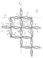
- the spacer is constructed of a plurality of intersecting webs 2, which form a grid with polygonal, in the embodiment square mesh 4, are passed through the fuel rods 5.
- Each web 2 is composed of a first and second sheet metal strips 6 and 8, which are welded together at their contacting upper and lower longitudinal edges.
- First and second sheet metal strips 6 and 8 are each provided with formations 10, 12 and 14, 16, each extending into the interior of the sheet metal strip 6 and 8 each limited mesh 4. These formations 10, 12, 14, 16 serve at the same time as bearings for the meshes 4 passing through the fuel rods 5. Between the formations 10, 14 and 12, 16 of each a web 2 forming the first and second metal strips 6, 8, a flow sub-channel 20 is formed in this way, in which the cooling water flows through the spacer in the vertical direction upward (out of the plane of the drawing).
- the flow sub-channels 20 are inclined along their entire length in the inclined plane to the vertical, that is to say in the direction of the vertical plane. H. inclined to a direction perpendicular to the plane of the drawing. This inclination causes a deflection of the flow inclined to the vertical, but always still parallel to the bank level.
- Each adjacent flow sub-channels 20 of a web 2 have an opposite inclination.
- the four flow subchannels 20 adjacent to a crossing point P are oriented such that two flow subchannels 20 arranged in a common web 2 incline toward one another while the two flow subchannels 20 belonging to the other web 2 are inclined away from one another.
- Each flow sub-channel 20 has a shape which is asymmetrical to a center plane 24 located between the sheet metal strips 6, 8 and oriented perpendicular to the plane of the drawing.
- the formations 10, 16 are each provided with a lower bulge 101 or 161, so that the formation 10 or 16 lies closer to the point of intersection P at this point.
- the respective formations 10 and 12 respectively assigned formations 14 and 16 have correspondingly in their upper region upper bulges 121 and 141, so that the cross-sectional area of the flow sub-channel 20 over the entire height of the web 2 remains approximately the same.
- the partial channel 110 or 116 respectively formed by the formations 10, 16 has a larger cross-sectional area than that of the formations 12, 14 due to the bulges 101 and 161, respectively, at the inlet of the flow sub-channel 20 Sub-channel 112 or 114.
- the sub-channels 110, 116 therefore branch off a larger amount of cooling water from the main channel formed by the mesh 4 than the sub-channels 112, 114. Since the cross-sections of the sub-channels 110, 116 constrict in the flow direction and the cross-sections of Extend sub-channels 112, 114, the cooling water flowing in the flow sub-channel 20 is shifted to the sub-channels 112 and 114, and obtained in this way a perpendicular to the web or center plane 24 flow component.
- the bulges 121 and 141 now cause that the cooling water flowing out of the flow subchannels 20 is not directed directly to the intersection point P, but obliquely past it, due to the velocity component perpendicular to the longitudinal direction 24. This creates a swirl flow around the crossing point P, which leads to an improved heat transfer between fuel rod and fluid.
- the formations 10, 12, 14, 16 are arranged such that the direction of the swirl flow of respectively adjacent crossing points 22 is opposite. In this way, it is prevented that the torques respectively exerted by the swirl flows add up to a total torque acting on the fuel assembly.
- the formations 10, 12, 14, 16 basically have the same shape.
- First and second metal strips 6 and 8 are arranged around an axis perpendicular to the sheet metal strip plane or center plane 24 twisted to each other.
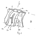
- the shape of the flow subchannels 20 is apparent in particular from the schematic diagram of Figure 3 clearly. It can be clearly seen in this figure that the greater part of the cooling water flowing in from below and branched off from the main channels from the flow subchannel 20 is taken up by the partial channel 110 formed by the formation 10, which has a lower bulge 101. Due to the cross-sectional constriction of the sub-channel 110, the cooling water flowing obliquely upwards along the entire length of the flow sub-channel 20 in the middle plane obliquely to the vertical (z-direction) is directed into the sub-channel 114 of the adjacent formation 14, thus obtaining a cross point next to one directed velocity component v x parallel to the rule level 24 a velocity component vy perpendicular thereto.
- the formations 10, 14 are each provided with longitudinal slots 26.
- a further increase in the transverse mass flow can also be achieved by providing windows 28 in the points of intersection P.
- the formations 10, 12, 14, 16 in the center of the web 2 still on both sides of the slot 26 have elongated bulges, which are directed into the interior of the mesh 4 and by their shape a line storage for the fuel rod form, so that this is resiliently supported in the mesh on eight lines.
- a relatively large velocity component v x parallel to the land level 24, ie a velocity component directed away from a crossing point P or directed towards a crossing point P, can be generated.
Abstract
Description
Die Erfindung bezieht sich auf einen Abstandhalter für ein Brennelement eines mit Leichtwasser gekühlten Kernreaktors, wie er beispielsweise aus der EP 0 237 064 A2 bekannt ist.The invention relates to a spacer for a fuel assembly of a light-water cooled nuclear reactor, as it is known for example from EP 0 237 064 A2.
Dieser bekannte Abstandhalter ist aus einer Vielzahl von sich kreuzenden Stegen aufgebaut, die ein Gitter mit einer Vielzahl von Maschen bilden. Jeder Steg ist durch zwei miteinander verschweißte dünne Blechstreifen gebildet. Diese Blechstreifen sind jeweils mit erhabenen Ausformungen versehen, die sich ins Innere der vom Blechstreifen jeweils begrenzten Gittermasche erstrecken. Jeweils einander gegenüberliegende, benachbarte Ausformungen der zu einem Steg zusammengefügten Blechstreifen bilden einen sich in vertikaler Richtung erstreckenden, annähernd rohrförmigen Strömungsunterkanal. Diese Strömungsunterkanäle sind relativ zur Vertikalen geneigt und erzeugen eine parallel zum Steg orientierte, auf einen Kreuzungspunkt der Stege gerichtete Strömungskomponente der Kühlflüssigkeit. Diese erzeugt eine Drallströmung um die die Maschen jeweils durchsetzenden Brennstäbe.This known spacer is constructed of a plurality of intersecting webs forming a grid with a plurality of meshes. Each web is formed by two thin metal strips welded together. These metal strips are each provided with raised formations that extend into the interior of the metal strip each limited grid mesh. Respectively adjacent, adjacent formations of the metal strips joined together to form a web form a vertically extending, approximately tubular flow subchannel. These flow subchannels are inclined relative to the vertical and produce a parallel to the web oriented, directed to a crossing point of the webs flow component of the cooling liquid. This generates a swirl flow around the fuel rods each passing through the mesh.
Bei dem bekannten Abstandhalter dienen diese Ausformungen außerdem zugleich als Lagerung für die die Maschen durchsetzenden Brennstäbe. Diese Brennstablagerung hat sich in der Praxis als besonders vorteilhaft herausgestellt, da bei der Verwendung solcher Abstandhalter nur geringe Frettingschäden an den Brennstabhüllrohren beobachtet werden.In the known spacer these formations also serve as storage for the mesh passing through the fuel rods. This fuel deposit has proven to be particularly advantageous in practice, since only small fretting damage to the fuel rod sheaths are observed when using such spacers.
Der Erfindung liegt nun die Aufgabe zu Grunde, einen Abstandhalter der eingangs genannten Art anzugeben, der bei hoher Frettingsicherheit zugleich verbesserte thermohydraulische Eigenschaften aufweist.The invention is based on the object to provide a spacer of the type mentioned, which has at the same time improved thermal-hydraulic properties at high safety against fretting.
Die genannte Aufgabe wird gemäß der Erfindung gelöst mit einem Abstandhalter mit den Merkmalen des Patentanspruches 1. Ein solcher Abstandhalter für ein Brennelement eines mit Leichtwasser gekühlten Kernreaktors ist aus einer Vielzahl von sich kreuzenden und ein Gitter bildenden Stegen aufgebaut, die jeweils aus miteinander verbundenen ersten und zweiten Blechstreifen bestehen. Diese Blechstreifen weisen Ausformungen derart auf, dass jeweils benachbarte Ausformungen einen Strömungsunterkanal bilden und derart gestaltet sind, dass sie dem aus dem Strömungsunterkanal austretenden Kühlwasser eine Strömungskomponente senkrecht zu einer zwischen den Blechstreifen verlaufenden vertikalen Mittenebene aufprägen. Dadurch wird eine verbesserte Querdurchmischung des Kühlwassers ermöglicht.The above object is achieved according to the invention with a spacer with the features of
Insbesondere nimmt der Querschnitt des durch eine erste Ausformung gebildeten Teilkanals in Strömungsrichtung des Kühlwassers ab und der Querschnitt des durch eine zweite, benachbarte Ausformung gebildeten Teilkanals nimmt in dieser Richtung zu. Mit anderen Worten: der Querschnitt des durch die erste Auformung gebildeten Teilkanals ist an der Eintrittsöffnung größer als an der Austrittsöffnung und der Querschnitt des durch die zweite Ausformung gebildeten Teilkanals ist an der Eintrittsöffnung kleiner als an der Austrittsöffnung. Diese Zunahme bzw. Abnahme des Querschnitts kann kontinuierlich über die gesamte Steghöhe erfolgen. Es sind jedoch auch Ausführungsformen möglich, bei denen ein Mittenbereich mit konstantem Querschnitt vorliegt. Durch diese voneinander verschiedene Gestalt der jeweils benachbarten Ausformungen lässt sich eine senkrecht zur Stegebene gerichtete Strömungskomponente durch fertigungstechnisch besonders einfache Formgebung der Blechstreifen erzeugen.In particular, the cross section of the sub-channel formed by a first formation decreases in the flow direction of the cooling water, and the cross-section of the sub-channel formed by a second, adjacent formation increases in this direction. In other words, the cross section of the sub-channel formed by the first formation is larger at the inlet opening than at the outlet opening and the cross-section of the sub-channel formed by the second embodiment is smaller at the inlet opening than at the outlet opening. This increase or decrease of the cross section can take place continuously over the entire web height. However, embodiments are also possible in which there is a central region with a constant cross section. Through these different from each other Shape of the respective adjacent formations can be a perpendicular to the bank level directed flow component produced by manufacturing technology particularly simple shaping of the metal strip.
In einer weiteren vorteilhaften Ausgestaltung der Erfindung weisen der erste und der zweite Blechstreifen jeweils erste und zweite Ausformungen auf, die abwechselnd in Längsrichtung des ersten und zweiten Blechstreifens angeordnet sind. Erster und zweiter Blechstreifen sind derart zu dem Steg zusammengefügt, dass jeder Strömungsunterkanal durch eine erste und zweite Ausformung gebildet ist. Ein solcher Blechstreifen und der damit gebildete Abstandhalter lassen sich einfach fertigen.In a further advantageous embodiment of the invention, the first and the second sheet-metal strips each have first and second formations, which are arranged alternately in the longitudinal direction of the first and second sheet metal strip. First and second sheet metal strips are joined to the web such that each flow subchannel is formed by a first and second molding. Such a metal strip and the spacer thus formed can be easily manufactured.
In einer bevorzugten Ausgestaltung der Erfindung verläuft der Strömungsunterkanal zumindest an seinem stromabwärtigen Ende schräg oder geneigt zur Vertikalen.In a preferred embodiment of the invention, the flow sub-channel runs at least at its downstream end obliquely or inclined to the vertical.
In einer weiteren bevorzugten Ausführungsform weist das aus den einander benachbarten und zu einem Kreuzungspunkt zweier Stege geneigten Strömungsunterkanäle eines Stegs jeweils austretende Kühlwasser einander entgegengesetzte Strömungskomponenten senkrecht zur Mittenebene auf, so dass eine Drallströmung um den Kreuzungspunkt erzeugt wird, wobei insbesondere die Drallströmungen um einander benachbarte Kreuzungspunkte entlang eines Steges jeweils entgegengesetzt gerichtet sind. Dadurch wird das Entstehen eines durch die Drallströmungen erzeugten und auf das gesamte Brennelement wirkenden Gesamtdrehmomentes verhindert.In a further preferred embodiment, the cooling water emerging from the flow sub-channels of a web which are adjacent to each other and inclined to a crossing point of two webs has opposite flow components perpendicular to the mid-plane, so that a swirl flow is generated around the intersection, in particular the swirl flows around mutually adjacent intersection points are directed opposite each other along a ridge. As a result, the emergence of a generated by the swirl flows and acting on the entire fuel assembly total torque is prevented.
Zur weiteren Erläuterung der Erfindung wird auf das Ausführungsbeispiel der Zeichnung verwiesen. Es zeigen:
- Fig. 1 eine Draufsicht auf einen Ausschnitt aus einem Abstandhalter gemäß der Erfindung in einer schematischen Prinzipdarstellung,
- Fig. 2 einen vergrößerten Ausschnitt des Abstandhalters im Bereich eines Kreuzungspunktes zweier Stege ebenfalls in einer Draufsicht,
- Fig. 3 einen Ausschnitt aus einem Steg im Bereich einer Ausformung in einer perspektivischen Darstellung,
- Fig. 4 einen Ausschnitt aus dem Steg in einer Seitenansicht.
- Fig. 5 eine weitere Ausgestaltung eines erfindungsgemäßen Strömungsunterkanals in einer schematischen perspektivischen Darstellung. -
- 1 is a plan view of a section of a spacer according to the invention in a schematic schematic diagram,
- 2 is an enlarged section of the spacer in the region of a crossing point of two webs also in a plan view,
- 3 is a detail of a web in the region of a molding in a perspective view,
- Fig. 4 shows a section of the web in a side view.
- Fig. 5 shows a further embodiment of a flow sub-channel according to the invention in a schematic perspective view. -
Gemäß Fig. 1 und 2 ist der Abstandhalter aus einer Vielzahl von sich kreuzenden Stegen 2 aufgebaut, die ein Gitter mit polygonalen, im Ausführungsbeispiel quadratischen Maschen 4 bilden, durch die Brennstäbe 5 hindurchgeführt sind. Jeder Steg 2 ist aus einem ersten und zweiten Blechstreifen 6 bzw. 8 zusammengesetzt, die an ihren sich berührenden oberen und unteren Längskanten miteinander verschweißt sind.According to Fig. 1 and 2, the spacer is constructed of a plurality of intersecting
Erster und zweiter Blechstreifen 6 bzw. 8 sind jeweils mit Ausformungen 10, 12 bzw. 14, 16 versehen, die sich jeweils in das Innere der vom Blechstreifen 6 bzw. 8 jeweils begrenzten Masche 4 erstrecken. Diese Ausformungen 10, 12, 14, 16 dienen zugleich als Lager für die die Maschen 4 durchsetzenden Brennstäbe 5. Zwischen den Ausformungen 10, 14 und 12, 16 der jeweils einen Steg 2 bildenden ersten und zweiten Blechstreifen 6, 8 ist auf diese Weise ein Strömungsunterkanal 20 gebildet, in dem das Kühlwasser durch den Abstandhalter in vertikaler Richtung nach oben (aus der Zeichenebene heraus) strömt.First and second
In den Figuren 1 und 2 ist zu erkennen, dass die Strömungsunterkanäle 20 auf ihrer gesamten Länge in der Stegebene geneigt zur Vertikalen, d. h. geneigt zu einer Richtung, die senkrecht auf der Zeichenebene steht, verlaufen. Diese Neigung bewirkt eine Ablenkung der Strömung geneigt zur Vertikalen, jedoch immer nach wie vor parallel zur Stegebene. Jeweils benachbarte Strömungsunterkanäle 20 eines Stegs 2 haben eine entgegengesetzte Neigung. Die vier einem Kreuzungspunkt P benachbarten Strömungsunterkanäle 20 sind dabei so orientiert, dass zwei in einem gemeinsamen Steg 2 angeordnete Strömungsunterkanäle 20 einander zugeneigt, während die zwei zum anderen Steg 2 gehörenden Strömungsunterkanäle 20 voneinander weggeneigt sind.In FIGS. 1 and 2 it can be seen that the
Jeder Strömungsunterkanal 20 weist eine Form auf, die asymmetrisch zu einer zwischen den Blechstreifen 6, 8 befindlichen und senkrecht zur Zeichenebene orientierten Mittenebene 24 ist. Die Ausformungen 10, 16 sind hierzu jeweils mit einer unteren Auswölbung 101 bzw. 161 versehen, so dass die Ausformung 10 bzw. 16 an dieser Stelle näher am Kreuzungspunkt P liegt. Die den Ausformungen 10 bzw. 12 jeweils zugeordneten Ausformungen 14 bzw. 16 weisen dementsprechend in ihrem oberen Bereich obere Auswölbungen 121 bzw. 141 auf, so dass die Querschnittsfläche des Strömungsunterkanals 20 über die gesamte Höhe des Steges 2 annähernd gleich bleibt.Each
Der von den Ausformungen 10, 16 jeweils gebildete Teilkanal 110 bzw. 116 hat aufgrund der Auswölbungen 101 bzw. 161 am Eingang des Strömungsunterkanals 20 eine größere Querschnittsfläche als der von den Ausformungen 12, 14 jeweils gebildete Teilkanal 112 bzw. 114. Die Teilkanäle 110, 116 zweigen deshalb eine größere Menge an Kühlwasser aus dem durch die Masche 4 gebildeten Hauptkanal ab als die Teilkanäle 112, 114. Da sich die Querschnitte der Teilkanäle 110, 116 in Strömungsrichtung verengen und die Querschnitte der Teilkanäle 112, 114 erweitern, wird das im Strömungsunterkanal 20 strömende Kühlwasser zu den Teilkanälen 112 bzw. 114 verlagert und erhält auf diese Weise eine zur Steg- oder Mittenebene 24 senkrechte Strömungskomponente.The
Mit anderen Worten: Durch die asymmetrische Formgebung der Ausformungen 10, 14 bzw. 12, 16, d. h. durch die versetzte Anordnung der Auswölbungen 101, 121, 141, 161 wird dem zwischen diesen Ausformungen 10, 14 bzw. 12, 16 strömenden Kühlwasser zusätzlich eine zur Mittenebene 24 des Stegs 2 senkrechte Geschwindigkeitskomponente verliehen, da das Kühlwasser eine Ablenkung zur Auswölbung 121 bzw. 141 erfährt.In other words, by the asymmetrical shaping of the
Alternativ zu der in den Figuren 1 bis 3 dargestellten Gestaltung der Ausformungen, bei der die Auswölbungen nur eine Vergrößerung der Ausformung in Richtung der Mittenebene 24 (Stegebene) bilden, ist es auch möglich, Auswölbungen vorzusehen, die sich tiefer ins Innere der Masche 4 erstrecken, wie dies anhand einer Auswölbung 200 gestrichelt in der Figur 1 in der rechten unteren Masche angedeutet ist, und den in den Ecken vorhandenen und vom Brennstab 5 freigelassenen Raum besser ausnutzen.As an alternative to the configuration of the formations shown in FIGS. 1 to 3, in which the bulges only increase the shape in the direction of the center plane 24 (slope level), it is also possible to provide bulges that extend deeper into the interior of the
Die Auswölbungen 121 und 141 bewirken nun, dass das aus den Strömungsunterkanälen 20 ausströmende Kühlwasser aufgrund der zur Längsrichtung 24 senkrechten Geschwindigkeitskomponente nicht direkt auf den Kreuzungspunkt P gerichtet sondern schräg an ihm vorbeigerichtet ist. Dies erzeugt eine Drallströmung um den Kreuzungspunkt P, die zu einem verbesserten Wärmeübergang zwischen Brennstab und Fluid führt. Darüber hinaus sind die Ausformungen 10, 12, 14, 16 derart angeordnet, dass die Richtung der Drallströmung jeweils benachbarter Kreuzungspunkte 22 entgegengesetzt ist. Auf diese Weise ist verhindert, dass sich die von den Drallströmungen jeweils ausgeübten Drehmomente zu einem auf das Brennelement wirkenden Gesamtdrehmoment addieren.The
Im Ausführungsbeispiel haben die Ausformungen 10, 12, 14, 16 grundsätzlich die gleiche Form. Erster und zweiter Blechstreifen 6 bzw. 8 sind jedoch um eine Achse senkrecht zur Blechstreifenebene oder Mittenebene 24 verdreht zueinander angeordnet.In the exemplary embodiment, the
Die Form der Strömungsunterkanäle 20 geht insbesondere aus dem Prinzipbild der Figur 3 deutlich hervor. In dieser Figur ist deutlich zu erkennen, dass der größere Teil des von unten anströmenden und aus den Hauptkanälen vom Strömungsunterkanal 20 abgezweigten Kühlwassers von dem Teilkanal 110 aufgenommen wird, der von der Ausformung 10 gebildet wird, die eine untere Auswölbung 101 aufweist. Das durch den auf seiner gesamten Länge schräg verlaufenden Strömungsunterkanal 20 in der Mittenebene schräg zur Vertikale (z-Richtung) nach oben strömende Kühlwasser wird aufgrund der Querschnittsverengung des Teilkanals 110 in den Teilkanal 114 der benachbarten Ausformung 14 gelenkt und erhält so neben einer zum Kreuzungspunkt hin gerichteten Geschwindigkeitskomponente vx parallel zur Stegebene 24 eine Geschwindigkeitskomponente vy senkrecht dazu.The shape of the
Zur Verbesserung der Mischung der Kühlflüssigkeit zwischen den einzelnen Hauptkanälen, d. h. zur Erhöhung des Quermassenstroms können, wie es in Figur 4 gezeigt ist, die Ausformungen 10, 14 jeweils mit Längsschlitzen 26 versehen sein.To improve the mixing of the cooling liquid between the individual main channels, ie to increase the transverse mass flow can, as shown in Figure 4, the
Eine weitere Erhöhung des Quermassenstromes kann auch dadurch erzielt werden, dass in den Kreuzungspunkten P Fenster 28 vorgesehen sind. Ebenso können wie beim bekannten HTP-Abstandhalter die Ausformungen 10, 12, 14, 16 in der Mitte des Steges 2 noch beidseitig des Schlitzes 26 längsgestreckte Auswölbungen aufweisen, die in das Innere der Masche 4 gerichtet sind und durch ihre Formgebung eine Linienlagerung für den Brennstab bilden, so dass dieser in der Masche insgesamt an acht Linien federnd gehaltert ist.A further increase in the transverse mass flow can also be achieved by providing
Dies ist im Ausführungsbeispiel gemäß Fig. 5 angedeutet. In dieser Figur sind beidseitig des Schlitzes 26 Auswölbungen 30 dargestellt. Darüberhinaus ist der von den Ausformungen 14 und 10 gebildete Strömungsunterkanal 20 abweichend von dem in Fig. 3 dargestellten Ausführungsbeispiel nicht auf seiner gesamten Länge 1 (= Steghöhe) geneigt zur Vertikalen z, sondern nur auf einem Teil a seiner Länge 1 an seinem stromabwärtigem Ende und ggf. auf einem Teil b seiner Länge 1 stromaufwärts. Im übrigen Teil 1-a bzw. 1-a-b verläuft der Strömungsunterkanal 20 im wesentlichen parallel zur Vertikalen z. Auf diese Weise kann bei kleinen Maschenweiten und großen Steghöhen (Länge 1 des Strömungsunterkanals 20) eine relativ große Geschwindigkeitskomponente vx parallel zur Stegebene 24, d.h. eine von einem Kreuzungspunkt P weg - bzw. zu einem Kreuzungspunkt P hin gerichtete Geschwindigkeitskomponente erzeugt werden.This is indicated in the embodiment of FIG. 5. In this figure, 26 bulges 30 are shown on both sides of the slot. In addition, the
Claims (7)
- Spacer for a fuel element of a nuclear reactor cooled by light water, which is constructed from a multiplicity of crisscrossing webs (2) that form a grid and respectively consist of interconnected first and second sheet-metal strips (6, 8) that have corrugations (10, 12, 14, 16) in such a way that in each case neighbouring corrugations (10, 14 and 12, 16, respectively) form a flow subchannel (20) that runs oblique to the vertical (z), characterized in that each flow subchannel (20) has a shape, which is asymmetric to a vertical middle plane (24) running between the sheet-metal strips (6, 8) in order to impart to the cooling water emerging from each flow subchannel a flow component (vy) perpendicular to the middle plane.
- Spacer according to Claim 1, in which the cross section of the partial channel (110 or 116) formed by a first corrugation (10, 16) decreases in the flow direction of the cooling water, and the cross section of the partial channel (114, 112) formed by a second, neighbouring corrugation (14 or 12) increases in this direction.
- Spacer according to Claim 1 or 2, in which the first and the second sheet-metal strips (6, 8) in each case have first and second corrugations (10, 12 and 14, 16, respectively) that are alternately arranged in the longitudinal direction (x) of the first and second sheet-metal strips (6, 8), and in which the first and second sheet-metal strips (6, 8) are assembled to form the web (2) in such a way that each flow subchannel (20) is formed by a first and second corrugation (10, 14 and 12, 16, respectively).
- Spacer according to Claim 1, 2 or 3, in which the flow subchannel (20) runs oblique to the vertical (z) at least at its downstream end.
- Spacer according to Claim 4, in which mutually neighbouring flow subchannels (20) of a web (2) are inclined to a crossing point (P) of two webs (2) in such a way that the cooling water emerging from them has mutually opposed flow components (vx) perpendicular to the middle plane (24) such that a swirl flow is produced around the crossing point (P).
- Spacer according to Claim 5, in which the swirl flows around mutually neighbouring crossing points (P) are respectively directed in an opposed fashion along a web (2).
- Fuel element having at least one spacer according to one of the preceding claims.
Applications Claiming Priority (3)
| Application Number | Priority Date | Filing Date | Title |
|---|---|---|---|
| DE10309742 | 2003-03-06 | ||
| DE10309742A DE10309742B4 (en) | 2003-03-06 | 2003-03-06 | spacer |
| PCT/EP2004/001515 WO2004079748A2 (en) | 2003-03-06 | 2004-02-18 | Spacer |
Publications (2)
| Publication Number | Publication Date |
|---|---|
| EP1540662A2 EP1540662A2 (en) | 2005-06-15 |
| EP1540662B1 true EP1540662B1 (en) | 2007-04-11 |
Family
ID=32891903
Family Applications (1)
| Application Number | Title | Priority Date | Filing Date |
|---|---|---|---|
| EP04712010A Expired - Lifetime EP1540662B1 (en) | 2003-03-06 | 2004-02-18 | Spacer |
Country Status (10)
| Country | Link |
|---|---|
| US (1) | US7418072B2 (en) |
| EP (1) | EP1540662B1 (en) |
| JP (1) | JP4376264B2 (en) |
| KR (1) | KR100763726B1 (en) |
| CN (1) | CN100334653C (en) |
| AT (1) | ATE359589T1 (en) |
| DE (2) | DE10309742B4 (en) |
| ES (1) | ES2283986T3 (en) |
| WO (1) | WO2004079748A2 (en) |
| ZA (1) | ZA200501198B (en) |
Families Citing this family (7)
| Publication number | Priority date | Publication date | Assignee | Title |
|---|---|---|---|---|
| US20110200160A1 (en) * | 2010-02-16 | 2011-08-18 | Westinghouse Electric Company | Split spring anti-fretting fuel rod support structure |
| JP5726674B2 (en) * | 2011-08-10 | 2015-06-03 | 原子燃料工業株式会社 | Lattice spacers for boiling water reactor fuel assemblies. |
| US10176899B2 (en) | 2012-09-04 | 2019-01-08 | Global Nuclear Fuel-Americas, Llc | Spacers with deflection-limited rod contacts for nuclear fuel assemblies and methods of making the same |
| US9564249B2 (en) * | 2013-03-05 | 2017-02-07 | Global Nuclear Fuel—Americas Llc | Spacers for nuclear fuel assemblies |
| CN104485137B (en) * | 2014-12-05 | 2017-04-26 | 中广核研究院有限公司 | Fuel assembly blending screenwork with rectifying type blending wings |
| KR102162012B1 (en) | 2019-01-16 | 2020-10-07 | 한전원자력연료 주식회사 | A bottom nozzle of Nuclear Fuel Assembly formed flow hole by utilizing a layered Aircraft Airfoil Structure |
| KR102413698B1 (en) * | 2020-05-18 | 2022-06-27 | 한전원자력연료 주식회사 | A bottom Fixture of Nuclear Fuel Assembly formed flow hole by a Aircraft Airfoil Structure forming a flow hole |
Family Cites Families (14)
| Publication number | Priority date | Publication date | Assignee | Title |
|---|---|---|---|---|
| GB1088022A (en) * | 1964-02-13 | 1967-10-18 | Atomic Energy Authority Uk | Nuclear fuel assemblies |
| US4039379A (en) * | 1975-02-28 | 1977-08-02 | Exxon Nuclear Company, Inc. | Mixing vane grid spacer |
| DE2647000C3 (en) * | 1976-10-18 | 1980-11-20 | Kraftwerk Union Ag, 4330 Muelheim | Spacer grids for fuel assemblies |
| US4726926A (en) * | 1986-03-12 | 1988-02-23 | Advanced Nuclear Fuels Corporation | Mixing grid |
| FR2666678B1 (en) * | 1990-07-24 | 1993-07-30 | Framatome Sa | GRILLE WITH MIXING FINS FOR NUCLEAR FUEL ASSEMBLY. |
| US5925657A (en) * | 1997-06-18 | 1999-07-20 | The General Hospital Corporation | Use of PPARγ agonists for inhibition of inflammatory cytokine production |
| US6526116B1 (en) * | 1997-07-02 | 2003-02-25 | Westinghouse Electric Company Llc | Nuclear fuel assembly with hydraulically balanced mixing vanes |
| EP0932162B1 (en) * | 1998-01-27 | 2004-03-31 | Framatome ANP GmbH | Spacer grid for a nuclear fuel assembly |
| KR100287278B1 (en) * | 1998-02-04 | 2001-04-16 | 장인순 | Nuclear fuel set supporting grid having rotating mobility generating device |
| KR100330358B1 (en) * | 1999-07-29 | 2002-04-01 | 장인순 | Spacer grid with multi-spring and embossed vane for PWR fuel assembly |
| DE29923315U1 (en) * | 1999-09-28 | 2000-09-21 | Siemens Ag | Fuel assembly with spacers for pressurized water reactors |
| JP4139223B2 (en) * | 2001-01-26 | 2008-08-27 | アレヴァ エンペー ゲゼルシャフト ミット ベシュレンクテル ハフツング | Reactor fuel assemblies and spacers |
| DE10107037A1 (en) * | 2001-02-15 | 2002-09-19 | Framatome Anp Gmbh | fuel element |
| KR100415149B1 (en) | 2001-03-21 | 2004-01-14 | 한국전력공사 | Double strip mixing grid for a nuclear fuel assembly |
-
2003
- 2003-03-06 DE DE10309742A patent/DE10309742B4/en not_active Expired - Fee Related
-
2004
- 2004-02-18 KR KR1020057013904A patent/KR100763726B1/en not_active IP Right Cessation
- 2004-02-18 DE DE502004003453T patent/DE502004003453D1/en not_active Expired - Lifetime
- 2004-02-18 WO PCT/EP2004/001515 patent/WO2004079748A2/en active IP Right Grant
- 2004-02-18 CN CNB2004800009867A patent/CN100334653C/en not_active Expired - Fee Related
- 2004-02-18 ES ES04712010T patent/ES2283986T3/en not_active Expired - Lifetime
- 2004-02-18 JP JP2006504430A patent/JP4376264B2/en not_active Expired - Fee Related
- 2004-02-18 EP EP04712010A patent/EP1540662B1/en not_active Expired - Lifetime
- 2004-02-18 AT AT04712010T patent/ATE359589T1/en not_active IP Right Cessation
-
2005
- 2005-02-10 ZA ZA2005/01198A patent/ZA200501198B/en unknown
- 2005-05-12 US US11/127,820 patent/US7418072B2/en not_active Expired - Fee Related
Also Published As
| Publication number | Publication date |
|---|---|
| DE10309742A1 (en) | 2004-09-23 |
| JP2006519987A (en) | 2006-08-31 |
| JP4376264B2 (en) | 2009-12-02 |
| KR100763726B1 (en) | 2007-10-04 |
| DE502004003453D1 (en) | 2007-05-24 |
| WO2004079748A3 (en) | 2004-11-18 |
| ES2283986T3 (en) | 2007-11-01 |
| DE10309742B4 (en) | 2005-01-27 |
| ATE359589T1 (en) | 2007-05-15 |
| US20060056574A1 (en) | 2006-03-16 |
| ZA200501198B (en) | 2005-10-26 |
| CN1701392A (en) | 2005-11-23 |
| WO2004079748A2 (en) | 2004-09-16 |
| KR20050105188A (en) | 2005-11-03 |
| US7418072B2 (en) | 2008-08-26 |
| EP1540662A2 (en) | 2005-06-15 |
| CN100334653C (en) | 2007-08-29 |
Similar Documents
| Publication | Publication Date | Title |
|---|---|---|
| EP0069241B1 (en) | Packing for material exchange columns, and process for producing the packing | |
| DE4111451C2 (en) | ||
| DE3108399A1 (en) | "FUEL ELEMENT BUNDLE FOR A BOILING WATER REACTOR" | |
| CH493814A (en) | Honeycomb installation for a trickle cooler | |
| EP1540662B1 (en) | Spacer | |
| EP1620861B1 (en) | Fuel element for a pressurized water reactor | |
| DE2712818A1 (en) | TUBULAR BODY | |
| DE10342241A1 (en) | heat exchangers | |
| AT393162B (en) | Plate heat exchanger with a special profile of the heat exchange (heat transfer) zone | |
| EP0587608A1 (en) | Fuel element with a grid structure between the rods. | |
| DE3122145A1 (en) | "ABSORPTION ORGAN FOR STATIONARY ARRANGEMENT IN THE GRILLE OF A BOILING WATER REACTOR" | |
| EP1588114B1 (en) | Cross-counterflow layered heat exchanger | |
| AT406301B (en) | PLATE HEAT EXCHANGER | |
| DE202008016603U1 (en) | Corrugated rib for heat exchanger | |
| DE1564697B2 (en) | Mixing plumes for the liquid coolant of nuclear reactors | |
| DE2123421A1 (en) | Cooling tower trickler structure - comprising - undulating pref plastic nets joined at undulations | |
| DE3915208C2 (en) | ||
| DE2813747A1 (en) | HEAT EXCHANGER BLADE AND APPLICATIONS OF THE SAME | |
| EP1483764B1 (en) | Spacer for the fuel element of a boiling water reactor | |
| EP1625594B1 (en) | Fuel element for a pressurised water nuclear reactor and core of a pressurised water nuclear reactor made of said fuel elements | |
| DE2260593A1 (en) | Nuclear fuel rod spacers - of skeletal construction with integral flow deflectors | |
| DE102011107122A1 (en) | Support for tubes in a shell-and-tube heat exchanger and method of making such support | |
| DE2326151A1 (en) | CORE REACTOR FUEL ELEMENT ARRANGEMENT | |
| DE2720756A1 (en) | Tube and fin heat exchanger - whose fins bear turbulence inducing ribs of specific dimension | |
| EP0195903A2 (en) | Plate-like heating element, particularly for floor heating |
Legal Events
| Date | Code | Title | Description |
|---|---|---|---|
| PUAI | Public reference made under article 153(3) epc to a published international application that has entered the european phase |
Free format text: ORIGINAL CODE: 0009012 |
|
| 17P | Request for examination filed |
Effective date: 20050415 |
|
| AK | Designated contracting states |
Kind code of ref document: A2 Designated state(s): AT BE BG CH CY CZ DE DK EE ES FI FR GB GR HU IE IT LI LU MC NL PT RO SE SI SK TR |
|
| AX | Request for extension of the european patent |
Extension state: AL LT LV MK |
|
| DAX | Request for extension of the european patent (deleted) | ||
| RAP1 | Party data changed (applicant data changed or rights of an application transferred) |
Owner name: AREVA NP GMBH |
|
| GRAP | Despatch of communication of intention to grant a patent |
Free format text: ORIGINAL CODE: EPIDOSNIGR1 |
|
| GRAS | Grant fee paid |
Free format text: ORIGINAL CODE: EPIDOSNIGR3 |
|
| GRAA | (expected) grant |
Free format text: ORIGINAL CODE: 0009210 |
|
| AK | Designated contracting states |
Kind code of ref document: B1 Designated state(s): AT BE BG CH CY CZ DE DK EE ES FI FR GB GR HU IE IT LI LU MC NL PT RO SE SI SK TR |
|
| PG25 | Lapsed in a contracting state [announced via postgrant information from national office to epo] |
Ref country code: SI Free format text: LAPSE BECAUSE OF FAILURE TO SUBMIT A TRANSLATION OF THE DESCRIPTION OR TO PAY THE FEE WITHIN THE PRESCRIBED TIME-LIMIT Effective date: 20070411 |
|
| REG | Reference to a national code |
Ref country code: GB Ref legal event code: FG4D Free format text: NOT ENGLISH |
|
| REG | Reference to a national code |
Ref country code: CH Ref legal event code: EP |
|
| REG | Reference to a national code |
Ref country code: IE Ref legal event code: FG4D Free format text: LANGUAGE OF EP DOCUMENT: GERMAN |
|
| REF | Corresponds to: |
Ref document number: 502004003453 Country of ref document: DE Date of ref document: 20070524 Kind code of ref document: P |
|
| REG | Reference to a national code |
Ref country code: CH Ref legal event code: NV Representative=s name: E. BLUM & CO. AG PATENT- UND MARKENANWAELTE VSP |
|
| REG | Reference to a national code |
Ref country code: SE Ref legal event code: TRGR |
|
| GBT | Gb: translation of ep patent filed (gb section 77(6)(a)/1977) |
Effective date: 20070627 |
|
| PG25 | Lapsed in a contracting state [announced via postgrant information from national office to epo] |
Ref country code: PT Free format text: LAPSE BECAUSE OF FAILURE TO SUBMIT A TRANSLATION OF THE DESCRIPTION OR TO PAY THE FEE WITHIN THE PRESCRIBED TIME-LIMIT Effective date: 20070911 |
|
| NLV1 | Nl: lapsed or annulled due to failure to fulfill the requirements of art. 29p and 29m of the patents act | ||
| ET | Fr: translation filed | ||
| REG | Reference to a national code |
Ref country code: ES Ref legal event code: FG2A Ref document number: 2283986 Country of ref document: ES Kind code of ref document: T3 |
|
| REG | Reference to a national code |
Ref country code: IE Ref legal event code: FD4D |
|
| RAP2 | Party data changed (patent owner data changed or rights of a patent transferred) |
Owner name: AREVA NP GMBH |
|
| PG25 | Lapsed in a contracting state [announced via postgrant information from national office to epo] |
Ref country code: NL Free format text: LAPSE BECAUSE OF FAILURE TO SUBMIT A TRANSLATION OF THE DESCRIPTION OR TO PAY THE FEE WITHIN THE PRESCRIBED TIME-LIMIT Effective date: 20070411 Ref country code: IE Free format text: LAPSE BECAUSE OF FAILURE TO SUBMIT A TRANSLATION OF THE DESCRIPTION OR TO PAY THE FEE WITHIN THE PRESCRIBED TIME-LIMIT Effective date: 20070411 Ref country code: BG Free format text: LAPSE BECAUSE OF FAILURE TO SUBMIT A TRANSLATION OF THE DESCRIPTION OR TO PAY THE FEE WITHIN THE PRESCRIBED TIME-LIMIT Effective date: 20070711 Ref country code: CZ Free format text: LAPSE BECAUSE OF FAILURE TO SUBMIT A TRANSLATION OF THE DESCRIPTION OR TO PAY THE FEE WITHIN THE PRESCRIBED TIME-LIMIT Effective date: 20070411 Ref country code: DK Free format text: LAPSE BECAUSE OF FAILURE TO SUBMIT A TRANSLATION OF THE DESCRIPTION OR TO PAY THE FEE WITHIN THE PRESCRIBED TIME-LIMIT Effective date: 20070411 |
|
| PLBE | No opposition filed within time limit |
Free format text: ORIGINAL CODE: 0009261 |
|
| STAA | Information on the status of an ep patent application or granted ep patent |
Free format text: STATUS: NO OPPOSITION FILED WITHIN TIME LIMIT |
|
| PG25 | Lapsed in a contracting state [announced via postgrant information from national office to epo] |
Ref country code: SK Free format text: LAPSE BECAUSE OF FAILURE TO SUBMIT A TRANSLATION OF THE DESCRIPTION OR TO PAY THE FEE WITHIN THE PRESCRIBED TIME-LIMIT Effective date: 20070411 |
|
| 26N | No opposition filed |
Effective date: 20080114 |
|
| PG25 | Lapsed in a contracting state [announced via postgrant information from national office to epo] |
Ref country code: IT Free format text: LAPSE BECAUSE OF FAILURE TO SUBMIT A TRANSLATION OF THE DESCRIPTION OR TO PAY THE FEE WITHIN THE PRESCRIBED TIME-LIMIT Effective date: 20070411 Ref country code: GR Free format text: LAPSE BECAUSE OF FAILURE TO SUBMIT A TRANSLATION OF THE DESCRIPTION OR TO PAY THE FEE WITHIN THE PRESCRIBED TIME-LIMIT Effective date: 20070712 |
|
| PG25 | Lapsed in a contracting state [announced via postgrant information from national office to epo] |
Ref country code: RO Free format text: LAPSE BECAUSE OF FAILURE TO SUBMIT A TRANSLATION OF THE DESCRIPTION OR TO PAY THE FEE WITHIN THE PRESCRIBED TIME-LIMIT Effective date: 20070411 |
|
| BERE | Be: lapsed |
Owner name: AREVA NP G.M.B.H. Effective date: 20080228 |
|
| PG25 | Lapsed in a contracting state [announced via postgrant information from national office to epo] |
Ref country code: MC Free format text: LAPSE BECAUSE OF NON-PAYMENT OF DUE FEES Effective date: 20080228 |
|
| REG | Reference to a national code |
Ref country code: CH Ref legal event code: PCOW Free format text: AREVA NP GMBH;PAUL-GOSSEN-STRASSE 100;91052 ERLANGEN (DE) |
|
| PG25 | Lapsed in a contracting state [announced via postgrant information from national office to epo] |
Ref country code: EE Free format text: LAPSE BECAUSE OF FAILURE TO SUBMIT A TRANSLATION OF THE DESCRIPTION OR TO PAY THE FEE WITHIN THE PRESCRIBED TIME-LIMIT Effective date: 20070411 |
|
| PG25 | Lapsed in a contracting state [announced via postgrant information from national office to epo] |
Ref country code: BE Free format text: LAPSE BECAUSE OF NON-PAYMENT OF DUE FEES Effective date: 20080228 |
|
| PG25 | Lapsed in a contracting state [announced via postgrant information from national office to epo] |
Ref country code: AT Free format text: LAPSE BECAUSE OF NON-PAYMENT OF DUE FEES Effective date: 20080218 |
|
| PG25 | Lapsed in a contracting state [announced via postgrant information from national office to epo] |
Ref country code: CY Free format text: LAPSE BECAUSE OF FAILURE TO SUBMIT A TRANSLATION OF THE DESCRIPTION OR TO PAY THE FEE WITHIN THE PRESCRIBED TIME-LIMIT Effective date: 20070411 |
|
| REG | Reference to a national code |
Ref country code: FR Ref legal event code: CA |
|
| PG25 | Lapsed in a contracting state [announced via postgrant information from national office to epo] |
Ref country code: HU Free format text: LAPSE BECAUSE OF FAILURE TO SUBMIT A TRANSLATION OF THE DESCRIPTION OR TO PAY THE FEE WITHIN THE PRESCRIBED TIME-LIMIT Effective date: 20071012 Ref country code: LU Free format text: LAPSE BECAUSE OF NON-PAYMENT OF DUE FEES Effective date: 20080218 |
|
| PG25 | Lapsed in a contracting state [announced via postgrant information from national office to epo] |
Ref country code: TR Free format text: LAPSE BECAUSE OF FAILURE TO SUBMIT A TRANSLATION OF THE DESCRIPTION OR TO PAY THE FEE WITHIN THE PRESCRIBED TIME-LIMIT Effective date: 20070411 |
|
| REG | Reference to a national code |
Ref country code: DE Ref legal event code: R082 Ref document number: 502004003453 Country of ref document: DE Representative=s name: MOERTEL, ALFRED, DIPL.-PHYS. DR.RER.NAT., DE |
|
| REG | Reference to a national code |
Ref country code: DE Ref legal event code: R081 Ref document number: 502004003453 Country of ref document: DE Owner name: AREVA GMBH, DE Free format text: FORMER OWNER: AREVA NP GMBH, 91052 ERLANGEN, DE Effective date: 20131112 Ref country code: DE Ref legal event code: R082 Ref document number: 502004003453 Country of ref document: DE Representative=s name: MOERTEL, ALFRED, DIPL.-PHYS. DR.RER.NAT., DE Effective date: 20131112 Ref country code: DE Ref legal event code: R082 Ref document number: 502004003453 Country of ref document: DE Representative=s name: MEISSNER BOLTE & PARTNER GBR, DE Effective date: 20131112 Ref country code: DE Ref legal event code: R082 Ref document number: 502004003453 Country of ref document: DE Representative=s name: MEISSNER BOLTE PATENTANWAELTE RECHTSANWAELTE P, DE Effective date: 20131112 |
|
| REG | Reference to a national code |
Ref country code: DE Ref legal event code: R082 Ref document number: 502004003453 Country of ref document: DE Representative=s name: MEISSNER BOLTE & PARTNER GBR, DE Ref country code: DE Ref legal event code: R082 Ref document number: 502004003453 Country of ref document: DE Representative=s name: MEISSNER BOLTE PATENTANWAELTE RECHTSANWAELTE P, DE |
|
| REG | Reference to a national code |
Ref country code: FR Ref legal event code: PLFP Year of fee payment: 12 |
|
| PGFP | Annual fee paid to national office [announced via postgrant information from national office to epo] |
Ref country code: DE Payment date: 20150216 Year of fee payment: 12 Ref country code: ES Payment date: 20150223 Year of fee payment: 12 Ref country code: FI Payment date: 20150218 Year of fee payment: 12 Ref country code: CH Payment date: 20150223 Year of fee payment: 12 |
|
| PGFP | Annual fee paid to national office [announced via postgrant information from national office to epo] |
Ref country code: SE Payment date: 20150223 Year of fee payment: 12 Ref country code: FR Payment date: 20150217 Year of fee payment: 12 |
|
| REG | Reference to a national code |
Ref country code: DE Ref legal event code: R082 Ref document number: 502004003453 Country of ref document: DE Representative=s name: MEISSNER BOLTE PATENTANWAELTE RECHTSANWAELTE P, DE |
|
| REG | Reference to a national code |
Ref country code: DE Ref legal event code: R119 Ref document number: 502004003453 Country of ref document: DE |
|
| REG | Reference to a national code |
Ref country code: CH Ref legal event code: PL |
|
| REG | Reference to a national code |
Ref country code: SE Ref legal event code: EUG |
|
| PG25 | Lapsed in a contracting state [announced via postgrant information from national office to epo] |
Ref country code: FI Free format text: LAPSE BECAUSE OF NON-PAYMENT OF DUE FEES Effective date: 20160218 Ref country code: LI Free format text: LAPSE BECAUSE OF NON-PAYMENT OF DUE FEES Effective date: 20160229 Ref country code: CH Free format text: LAPSE BECAUSE OF NON-PAYMENT OF DUE FEES Effective date: 20160229 |
|
| REG | Reference to a national code |
Ref country code: FR Ref legal event code: ST Effective date: 20161028 |
|
| PG25 | Lapsed in a contracting state [announced via postgrant information from national office to epo] |
Ref country code: SE Free format text: LAPSE BECAUSE OF NON-PAYMENT OF DUE FEES Effective date: 20160219 |
|
| PG25 | Lapsed in a contracting state [announced via postgrant information from national office to epo] |
Ref country code: DE Free format text: LAPSE BECAUSE OF NON-PAYMENT OF DUE FEES Effective date: 20160901 Ref country code: FR Free format text: LAPSE BECAUSE OF NON-PAYMENT OF DUE FEES Effective date: 20160229 |
|
| PG25 | Lapsed in a contracting state [announced via postgrant information from national office to epo] |
Ref country code: ES Free format text: LAPSE BECAUSE OF NON-PAYMENT OF DUE FEES Effective date: 20160219 |
|
| PGFP | Annual fee paid to national office [announced via postgrant information from national office to epo] |
Ref country code: GB Payment date: 20190221 Year of fee payment: 16 |
|
| REG | Reference to a national code |
Ref country code: GB Ref legal event code: 732E Free format text: REGISTERED BETWEEN 20190725 AND 20190731 |
|
| GBPC | Gb: european patent ceased through non-payment of renewal fee |
Effective date: 20200218 |
|
| PG25 | Lapsed in a contracting state [announced via postgrant information from national office to epo] |
Ref country code: GB Free format text: LAPSE BECAUSE OF NON-PAYMENT OF DUE FEES Effective date: 20200218 |