EP1540568B1 - Verfahren zur kommunikation zwischen einer zentralstation und mehreren transpondern sowie ein kommunikationsgerät - Google Patents
Verfahren zur kommunikation zwischen einer zentralstation und mehreren transpondern sowie ein kommunikationsgerät Download PDFInfo
- Publication number
- EP1540568B1 EP1540568B1 EP03791777A EP03791777A EP1540568B1 EP 1540568 B1 EP1540568 B1 EP 1540568B1 EP 03791777 A EP03791777 A EP 03791777A EP 03791777 A EP03791777 A EP 03791777A EP 1540568 B1 EP1540568 B1 EP 1540568B1
- Authority
- EP
- European Patent Office
- Prior art keywords
- bursts
- transponders
- central monitoring
- transponder
- bit
- Prior art date
- Legal status (The legal status is an assumption and is not a legal conclusion. Google has not performed a legal analysis and makes no representation as to the accuracy of the status listed.)
- Expired - Lifetime
Links
Images


Classifications
-
- G—PHYSICS
- G06—COMPUTING OR CALCULATING; COUNTING
- G06K—GRAPHICAL DATA READING; PRESENTATION OF DATA; RECORD CARRIERS; HANDLING RECORD CARRIERS
- G06K7/00—Methods or arrangements for sensing record carriers, e.g. for reading patterns
- G06K7/10—Methods or arrangements for sensing record carriers, e.g. for reading patterns by electromagnetic radiation, e.g. optical sensing; by corpuscular radiation
- G06K7/10009—Methods or arrangements for sensing record carriers, e.g. for reading patterns by electromagnetic radiation, e.g. optical sensing; by corpuscular radiation sensing by radiation using wavelengths larger than 0.1 mm, e.g. radio-waves or microwaves
- G06K7/10019—Methods or arrangements for sensing record carriers, e.g. for reading patterns by electromagnetic radiation, e.g. optical sensing; by corpuscular radiation sensing by radiation using wavelengths larger than 0.1 mm, e.g. radio-waves or microwaves resolving collision on the communication channels between simultaneously or concurrently interrogated record carriers.
- G06K7/10029—Methods or arrangements for sensing record carriers, e.g. for reading patterns by electromagnetic radiation, e.g. optical sensing; by corpuscular radiation sensing by radiation using wavelengths larger than 0.1 mm, e.g. radio-waves or microwaves resolving collision on the communication channels between simultaneously or concurrently interrogated record carriers. the collision being resolved in the time domain, e.g. using binary tree search or RFID responses allocated to a random time slot
- G06K7/10039—Methods or arrangements for sensing record carriers, e.g. for reading patterns by electromagnetic radiation, e.g. optical sensing; by corpuscular radiation sensing by radiation using wavelengths larger than 0.1 mm, e.g. radio-waves or microwaves resolving collision on the communication channels between simultaneously or concurrently interrogated record carriers. the collision being resolved in the time domain, e.g. using binary tree search or RFID responses allocated to a random time slot interrogator driven, i.e. synchronous
-
- G—PHYSICS
- G06—COMPUTING OR CALCULATING; COUNTING
- G06K—GRAPHICAL DATA READING; PRESENTATION OF DATA; RECORD CARRIERS; HANDLING RECORD CARRIERS
- G06K7/00—Methods or arrangements for sensing record carriers, e.g. for reading patterns
- G06K7/0008—General problems related to the reading of electronic memory record carriers, independent of its reading method, e.g. power transfer
Definitions
- the present invention relates to wireless communication systems and, more particularly, relates to a wireless communication system in which a central monitoring terminal is in communication with multiple monitored devices.
- wireless communications in any environment makes it possible for individual objects of interest to be added to, or removed from, the larger group of objects without incurring significant costs associated with installing or removing a fixed communications media.
- Conventional systems for providing such wireless communications employ a central transceiver (interrogator) that is in communication with the transponders.
- the transponders which commonly are referred to as radio frequency identification (or “RFID”) transponders (or “tags”), are capable of receiving an inquiry signal from the central transceiver and providing information back to the central transceiver in response to those inquiries.
- RFID radio frequency identification
- the RFID transponders in conventional systems typically send information to the transceiver by way of signals employing Amplitude Shift Keying (ASK) or Frequency Modulation (FM). Because these signal formats are employed, the information signals being sent by the transponders to the transceiver are "on" (e.g., nonzero signal levels are being transmitted) from about 50% to 100% of the overall time period over which the ASK signals are being sent. Such continuous or nearly-continuous transmission signals require large amounts of energy which limits the transmission range of the system. Further, as the proportion of on time reaches such high levels, the probability of collisions between (e.g., interference among) information signals originating from different transponders becomes high as the number of transponders in communication with the transceiver increases.
- ASK Amplitude Shift Keying
- FM Frequency Modulation
- US 2002/008633 on which the preambles of claims 1 and 17 are based discloses a method of identifying transmitters by transmitting portions of identifying information from transmitters to a controller at periodic intervals, and subsequently identifying the transmitters based on the time of arrival of portions of the identifying information.
- EP1017005 discloses a system comprising an interrogator, which sends interrogation bursts in a periodical manner, and transponders which send a response back with a random delay related to and end-of-burst interrogation event.
- US 2002/0087436 discloses a method for accounting for a plurality of items including a first step of transmitting information signals from individual ones of the items to as transceiver based upon random times. The random times occur as as function of a first specified time interval.
- the present inventor has discovered a new communication method in which multiple transponders transmit information to a central monitoring terminal in the form of a pulsed packets or bursts of a sub-carrier.
- the present invention provides a method of communicating information from first and second transponders to a central monitoring device, the method comprising:
- the present invention also provides a communications apparatus comprising:
- Bursts at two distinct subcarrier frequencies may be respectively transmitted, where one subcarrier frequency signifies a data change from a low level to a high level (e.g., zero to one) in the data stream, and the other subcarrier signifies a change from a high level to a low level (e.g., one to zero) in the data stream.
- the bursts of all of the transponders may occur within a time window or "data frame” comprising a particular set of periods or "bit-cells", where the length of the bit-cells is based upon a submultiple of the common continuous wave interrogation signal (frequency) from the central station.
- Each of the different transponders may be configured to transmit its respective burst(s) only at one or more sets of potential transmission times during the data frame.
- the potential transmission times of each tag may occur at the same time after the start of each successive bit-cell.
- the transponders need not transmit bursts at each of their potential transmission times. Rather, for Non-Return-to-Zero modulation (NRZ), while the transmission of a burst signifies a change in the value of the data stream being sent, the absence of the transmission of a burst at a known potential transmission time also provides information to the central monitoring terminal, namely that the value of the data stream has remained constant since the last potential transmission time.
- NMR Non-Return-to-Zero modulation
- the timing of the sets of potential transmission times in relation to the timing of the set of bit-cells may relate to the modulation method chosen (e.g., whether the potential transmission times occur at 1 ⁇ 4 of the way through the respective bit-cells rather than 1 ⁇ 2 or 3 ⁇ 4 of the way through the respective bit-cells) determined by the modulation method in the transponders themselves.
- Each transponder may be programmed with a seme-unique random seed that sets the start of its potential transmission times.
- the tags may reseed the start delay such that the potential transmission delay times of the different transponders will typically occur at sufficiently different times that the actual transmitted bursts are interleaved among one another and little or no inferference among the various transponders occurs.
- the central monitoring terminal may be configured to read and store the information received from the transponders and to correlate information received at appropriately-spaced time intervals as being provided by the same transponders. Specifically, the central monitoring terminal may transmit a continuous carrier during an interrogation period (e.g., the data frame plus some additional time) that is sufficiently long to allow for all transponders to complete their transmission sequences. Typically, assuming that one bit of data is transmitted by each transponder per bit-cell period (Manchester Modulation), the interrogation period may last for the number of bits of data to be transmitted by each of the transponders plus one, multiplied by the bit-cell period. During the interrogation period, the central monitoring terminal may record the values associated with the bursts in memory bins corresponding to time slots. The number of memory bins/time slots may be equal to or greater than the product of the number of bit-cells multiplied by the ratio of the time length of a bit-cell to the time length of the burst.
- an interrogation period e.g
- all of the transponders may stop sending data and go into a listen mode.
- the central monitoring terminal may then begin to transmit checksums of the information received from the different transponders it read successfully, by way of modulating the carrier. Any transponder that receives a checksum equal to its own may disable further transmission. When all checksums have been sent, the central monitoring terminal may stop providing the modulated carrier. If any transponders have not received the proper checksums from the central monitoring system, following a brief interruption of the carrier, those transponders may randomly predetermine the starting times for their sequences of potential transmission times. Upon reassertion of the carrier, these transponders may begin data transmission again. This sequence may repeat until all of the transponders have successfully communicated their information to the central monitoring terminal.
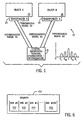
- Fig. 1 is a schematic diagram showing a wireless communication system employing two transponders associated with two respective objects of interest, and a central monitoring terminal;
- Fig. 2 is a timing diagram showing exemplary transmission signals that are transmitted by the two transponders of Fig. 1 , as well as timed information signals that are the basis for the transmission signals;
- Fig. 3 is a timing diagram showing, in schematic form, the signal output of the central monitoring terminal
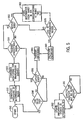
- Figs. 4 and 5 are flow charts showing exemplary steps of operation of the transponders and the central monitoring terminal of Fig. 1 , respectively;
- Fig. 6 is a schematic diagram of an exemplary memory of the central monitoring terminal of Fig. 1 .
- an exemplary wireless communication system 10 employs one or more transponders or "tags" that are in communication with a central monitoring terminal 15.
- first and second transponders 20 and 30, respectively are in communication with the central monitoring terminal 15, although in alternate embodiments only one, or more than two, transponders are in communication with the central monitoring terminal.
- the present invention is particularly suited for allowing communication between a large number of (e.g., one thousand or more) transponders and the central monitoring terminal 15.
- the first and second transponders 20,30 are attached to first and second objects 25 and 35, respectively.
- the objects 25,35 can be any objects for which the presence or operational status may be of interest.
- the objects 25,35 can be machine components located in a factory, items stored within a warehouse, appliances within a house, medical devices or other items in a hospital, or any of a variety of other objects.
- the transponders 20,30 are entirely distinct devices from the objects 25,35 to which they are attached, such that the transponders form "tags" on those objects of interest.
- the transponders 20,30 are not in communication with the objects 25,35, and can be attached to the objects by any conventional attachment device or technique (e.g., by screws or adhesives or implantation).
- one or more of the transponders 20,30 can be in communication with the respective objects 25,35 and receive status information therefrom, which in turn can be transmitted by the transponders to the central monitoring terminal 15.
- the transponders 20,30 are integrally formed as parts of the objects 25,35, respectively, or the objects of interest to be monitored simply are the transponders themselves.
- the design of the transponders and the central monitoring terminal can employ conventional components used for wireless signal transmission and reception, e.g., amplifiers, antennas, modulators, demodulators, and receivers.
- the components of these devices also include, in the present embodiment, signal processing components and memory devices.
- the communication between the transponders 20,30 and the central monitoring terminal 15 includes two components, an interrogation signal 55 transmitted by the central monitoring terminal, and first and second transmission signals 50 and 60 transmitted by the first and second transponders, respectively.
- the interrogation signal 55 is transmitted at a particular carrier frequency C, while the transmission signals 50,60 are transmitted at lower and upper sidebands S L and S H about the carrier frequency (as shown in Fig. 1 ). So long as the transmission signals 50,60 do not include signal components at the carrier frequency (e.g., the carrier is suppressed), the interrogation signal 55 can coexist with the transmission signals without interference.
- the interrogation signal 55 and the transmission signals 50,60 need not be related as carrier and sidebands, and can be other signals, so long as the interrogation signal does not interfere with the transmission signals.
- exemplary timed information signals 110,120 generated by the first and second transponders 20,30, respectively are shown.
- the timed information signals 110,120 are data streams of binary information that are to be transmitted by the transponders 20 and 30, respectively.
- the transmission signals 50 and 60 are each a series of pulse or bursts generated based upon the timed information signals 110, 120, respectively.
- the information being transmitted can be identification information, presence information, status information, or other types of information concerning the objects 25,35 and/or the transponders 20,30.
- Each of the timed information signals 110,120 is shown in two views, one which shows a portion of the respective timed information signal over a longer amount of time, and one which shows a portion of the respective signal over a shorter amount of time in greater detail (exploded from the view of the longer portion). Additionally, portions of the transmission signal 50,60 are shown in further detail to reveal two of the bursts transmitted as part of those signals.
- the transponders 20,30 communicate their entire data streams (e.g., all of their transmitted bursts) within a data frame 40, which comprises a particular number of periods or "bit-cells" 45 having a time length of ⁇ .
- the time length ⁇ of the bit-cells is based upon (typically a multiple of) the period of the carrier signal C, and is recognized by each of the transponders 20,30.
- the timed information signals 110,120 vary, and the transmission signals 50,60 transmit bursts, only at particular potential transmission times.
- the potential transmission times of each of the transponders 20,30 are one or more sets of times that occur periodically at the same frequency as the bit-cells 45.
- the potential transmission times of the first transponder 20 occur at the beginning of each bit-cell 45.
- a transponder it is possible a transponder to have potential transmission times that occur at a multiple of the frequency of the bit-cells 45 (e.g., two potential transmission times per bit-cell).
- the series of multiple potential transmission times can be looked upon as multiple sets of potential transmission times, where each set includes one potential transmission time per bit-cell.
- timed information signals 110 and 120 are formatted in accordance with the NRZ signal format, and consequently only experience transitions from low to high levels or high to low levels at the beginning of new periods having the length ⁇ .
- one or more transponders could produce timed information signals formatted in accordance with another signal format.
- Such signal formats could include, for example, the Manchester format, with transitions able to occur once per bit cell (e.g., multiples of ⁇ ), and the self-clocking (RTZ) format, with transitions able to occur at 1/4 or 3/4 of each successive period (or other formats, such as the N of M format).
- the method is simply modulation independent.
- the NRZ methods allow for the greatest number of tags being used with out interference.
- the timed information signals 110,120 of Fig. 2 each represent series of binary values where, e.g., a high value of a timed information signal represents a one and a low value represents a zero.
- the binary value of the signal is updated whenever the signal can experience a transition in accordance with its particular signal format, e.g., whenever another potential transmission time occurs.
- the timed information signal 110 experiences updated binary values after the passage of each successive period ⁇ .
- the first and second transponders 20,30 are configured to output nonzero transmission signals 50,60 in the form of bursts only at times when the first and second timed information signals 110,120 respectively experience transitions in the form of rising or falling edges.
- the burst times and polarities are obtained by differentiating the timed information signals. That is, in response to rising edges, the transponders 20,30 generate bursts at one subcarrier 170 while, in response to falling edges, the transponders generate bursts at the other subcarrier 180 (although the polarities of the bursts could be reversed in alternate embodiments).
- the transmission signals 50,60 represent a zero to one data change 170 as a burst at the sideband frequencies S H shown in Fig. 1 , and represent the one to zero data change as a burst 180 at the sideband frequencies S L shown in Fig. 1 .
- the bursts 170,180 of the transmission signals 50,60 corresponding to the transitions of the timed information signals 110,120 are not instantaneous. Rather, the bursts are sinusoidal signals that have a length that is short in comparison with the bit-cell period ⁇ (or the fractions of the period ⁇ ) at which potential transmission times occur. In one embodiment, the burst width is determined by the bit-cell width divided by the number of random seeds possible.
- the bursts 170,180 in comparison with the bit-cell period ⁇ (or the fractions of the period ⁇ ) at which bursts can occur, there is significant dead time in between the successive bursts of any given transmission signal such that the bursts of the different transmission signals can be interleaved among one another without interfering with one another.
- the lengths of the bursts 170 and 180 are ⁇ /100 while the time periods in between successive bursts of each transmission signal are at least 99 ⁇ /100.
- the transmission signals must be timed so that potential transmission times of the signals (and consequently the transmitted bursts 170,180) occur at different times and are spaced apart from one another by at least a minimum amount of dead time.
- the time in between successive pulses must at least be long enough to allow for oscillation in an antenna (not shown) of the central monitoring terminal 15 to die down after being excited by the first pulse.
- the dead time between successive bursts of any two transmission signals should be at least about 8 to 10 cycles of the carrier frequency to avoid interference between the pulses.
- a minimum dead time D between successive pulses is shown to be about ⁇ /10, although in many embodiments the minimum dead time could be significantly shorter relative to the particular bit-cell period n of the transmission signals.
- the transponders 20,30 are programmed to randomly select the start times for their respective timed information signals 110,120/transmission signals 50,60.
- the first potential transmission time (and first actual transmitted bursts 170) for the first transponder 20 is shown to occur at time 75
- the first potential transmission time (and first actual transmitted burst 170) for the second transponder 30 is shown to occur at time 85.
- the first two bursts 170 of the first and second transponders 20,30 of Fig. 2 are shown to be the temporal distance D apart from one another, such that the bursts do not interfere with one another.
- the probability that random timing of the transmission signals will avoid interference between bursts decreases.
- the number of transmission signals from different transponders that can be transmitted without interference simply by randomly selecting the starting time for the different signals is much larger than two, and can easily be in the hundreds. For example, in one embodiment, assuming a 900MHz carrier and 90MHz for the high subcarrier (shifted symmetrically from the carrier) and 81.8MHz for the low subcarrier, the pulse duration of each pulse could be about 100 nanoseconds.
- the present invention communicates by way of transmitting short bursts that are interleaved among one another, the present invention allows for communication between many transponders and a central monitoring terminal in a manner that requires significantly less bandwidth and power than conventional systems.
- the actual transit time utilization of each transponder is the width of the filamentary transmissions times (bursts) multiplied by the number of bursts, and the duty cycle of each transponder is simply the number of bursts * Burst Width / data frame length in time (e.g., the period ⁇ ). Since the duty cycle of the transmitted data is small, large transmitted field strengths back to the central terminal are possible while maintaining very low (average) operating currents in the transponders. That is, because the duty cycle is much shorter than in conventional systems, the same amount of information can be transmitted using much less energy than would be required in conventional systems.
- a timing diagram shows, in schematic form, the signal output of the central monitoring terminal 15 in relation to the transponders 20,30.
- the interrogation process begins when the central monitoring terminal 15 switches on the transmission of the interrogation signal 55, that is, the carrier signal C. This signal typically then remains on for an interrogation period 90, which is equal in length to the data frame 40 plus one additional bit-cell period ⁇ 95.
- the interrogation period 90 exceeds the data frame 40 by the additional period 95 because the randomly-selected startup times for the different transponders can delay the transmission signals of the transponders by up to one bit-cell period n (assuming that the potential transmission times of the transponders occur at the same frequency as the bit-cells, rather than at a multiple thereof).
- the central monitoring terminal 15 determines checksums concerning the data received from each of the transponders.
- the central monitoring terminal 15 then modulates the carrier signal C to send back the checksums to the different transponders.
- the checksums can be sent back sequentially, to each of the different transponders.
- Fig. 3 shows a first checksum period 96 during which the central monitoring terminal 15 sends back checksum information corresponding to the first transponder 20, a second checksum period 97 during which the terminal sends back checksum information corresponding to the second transponder 30, and an additional checksum period 98 during which the terminal could send back additional checksum information to another transponder (not shown).
- exemplary steps of operation of a transponder such as the first and second transponders 20,30 are shown.
- the transponder listens for the interrogation signal 55 from the central monitoring terminal 15. As long as the interrogation signal 55 is not present, the transponder remains at decision block 210 in a waiting mode. Once the interrogation signal 55 becomes present, the transponder determines randomly the start time for its corresponding timed information signal (and transmission signal and potential transmission times), at step 220. Then, at step 230, the transponder starts providing the timed information signal containing the data that is to be transmitted, based upon the randomly selected start time.
- the transponder determines whether a potential transmission time is occurring (or is about to occur) in accordance with the particular signal format that is being employed (e.g., NRZ, Manchester, etc.) and the bit-cell period ⁇ of operation. Then, at step 250, the transponder again determines whether the interrogation signal 55 continues to be present. If the interrogation signal 55 no longer is present, the transponder returns to the waiting mode in which it again listens for the interrogation signal (step 210). If the interrogation signal 55 continues to be present, the transponder then determines at step 260 whether a burst should be transmitted at the particular potential transmission time that is occurring. In the embodiment discussed with reference to Figs.
- bursts are only transmitted as part of the transmission signals 50,60 when rising or falling edges occur in the timed information signals 110,120. That is, if a timed information signal remains constant through a potential transmission time, then no burst is transmitted at that transition time.
- the transponder determines whether a burst should be provided, then the transponder transmits the burst at step 270 as part of its respective transmission signal (e.g., transmission signal 50,60). Upon providing the burst, or if the transponder determines that no burst should be provided, the transponder then determines whether the data stream is complete (which typically corresponds to whether the data frame 40 plus one bit-cell period n, i.e., the interrogation period 90, has expired). That is, the transponder determines whether all of the data that is to be transmitted as part of its transmission signal has been sent.
- the data stream is complete (which typically corresponds to whether the data frame 40 plus one bit-cell period n, i.e., the interrogation period 90, has expired). That is, the transponder determines whether all of the data that is to be transmitted as part of its transmission signal has been sent.
- the transponder returns to step 240 to determine when another transition time occurs. However, if at step 280 it is determined that the transponder's entire data stream has been transmitted, the transponder then awaits a response from the central monitoring terminal 15 in the form of a checksum (as discussed with reference to Fig. 3 ). If the transponder receives the correct checksum at step 290, the transponder will have effectively completed its transmission operation, and consequently the transponder returns to the listen mode at step 210. However, if the checksum provided to the transponder is incorrect, the transponder returns to step 220 and begins retransmission of its data until such time as the interrogation signal ceases.
- a checksum as discussed with reference to Fig. 3
- exemplary steps of operation of the central monitoring terminal 15 when operating with transponders such as transponders 20,30 are shown.
- the central monitoring terminal 15 commences providing the interrogation signal 55, at step 310. Further, upon providing the interrogation signal 55, the central terminal 15 at step 320 then begins to monitor for transmission signals such as signals 50,60 from one or more transponders.
- the central monitoring terminal 15 determines whether it has received an unacceptable signal indicative of interference or improper transmission by one or more of the transponders. If this is the case, the central monitoring terminal 15 stops providing the interrogation signal 340 at step 400.
- the central monitoring terminal 15 in the present embodiment then returns to step 310 to restart the interrogation signal 55.
- the central monitoring terminal 15 By stopping and starting the interrogation signal 55 (with a sufficient delay in between, e.g., several bit-cell periods ⁇ ), all of the transponders will also restart their transmission signals at different, randomly-determined times (as discussed with reference to Fig. 4 ), such that the interference between bursts of the different transponders no longer is likely to exist.
- the central monitoring terminal 15 monitors for bursts at step 350 (that is, the terminal cycles between steps 330 and 350). Upon receiving a burst, the central monitoring terminal 15 stores information from the burst in memory at step 360.
- the central terminal 15 in particular is capable of identifying and associating bursts that have been transmitted from the same transponder, even though those pulses are received at different times and are interleaved with bursts that have been transmitted from other transponders.
- the central monitoring terminal 15 is able to correlate bursts with transponders by associating those pulses that differ from one another in time by the bit-cell period ⁇ (or appropriate fractions thereof, e.g., a half-period ⁇ /2).
- the central monitoring terminal 15 in the present embodiment includes a memory device 410 that is divided into multiple bins/arrays (e.g., bins 420-450) that correspond to different time slots within the bit-cell period ⁇ that is common to all of the transmission signals of the different transponders.
- the number of bins is at least equal to the maximum number of bursts that could occur within a given bit-cell period ⁇ (e.g., ⁇ /burst width) or, in alternate embodiments, the maximum number of bursts that could occur without interference between neighboring bursts (e.g., ⁇ /D).
- the memory 410 should have at least one-hundred of the bins 420-450 as shown in Fig. 6 (in which bin 450 is bin #100).
- the data stored in any given bin of the memory device 410 corresponds to a respective transponder.
- the number of bins associated with any given transponder will depend upon the number of potential transmission times that occur per bit-cell period n at which that transponder can potentially send bursts, which in turn depends upon the signal format of the given transponder (e.g., a transponder transmitting in the Manchester format will typically have two bins, while a transponder transmitting in NRZ format will typically have a single bin).
- the central monitoring terminal 15 also gains additional information when bursts do not occur at appropriate potential transmission times.
- the first transmission signal 50 only includes bursts at the beginning of the first, second and fifth periods but not at the beginning of the third and fourth periods.
- the central monitoring terminal 15 operates to update the information stored in the bins 420-450 whenever potential transmission times occur, even when bursts do not occur.
- the central monitoring terminal 15 repeats the storing of the information that was previously stored as a result of the last received burst, at step 362.
- the values stored in the bin 420 of the memory device 410 corresponding to the first transmission signal 50 following the passage of the first six bit-cell periods will be 1,0,0,0,1,0, even though no bursts are received by the central monitoring terminal 15 at the beginning of the third and fourth periods.
- the central monitoring terminal 15 automatically stores a value of 0 upon the beginning of the third and fourth bit-cell periods ⁇ , subsequent to the burst 180 occurring at the beginning of the second bit-cell period ⁇ , since that last burst represented a value of 0.
- the central monitoring terminal 15 continues to monitor for transmitted bursts until the end of the interrogation period 90, at step 370. Upon the ending of the interrogation period 90, the central monitoring terminal 15 calculates checksums corresponding to the different transponders with which central monitoring terminal is in communication, at step 380. Specifically, the central monitoring terminal 15 calculates checksums corresponding to each bin (or groups of bins containing information from the same transponder). The central monitoring terminal 15 then transmits the checksums back to the transponders by way of the carrier signal, at step 390 (corresponding to periods 96-98 of Fig. 3 ). The central monitoring terminal 15 then awaits, at steps 395 and 398 for one or more the transponders to resend their information if the returned checksums are not correct (as discussed with reference to step 290 of Fig. 4 ).
- the central monitoring terminal 15 If new bursts are received within a certain time delay, the central monitoring terminal returns to steps 330-370 to continue to receive information. However, if no new bursts are received, the central monitoring terminal 15 concludes that all of the received information was correct and ends its operation (or returns to the beginning of the cycle). In alternate embodiments the central monitoring terminal 15 is able to determine by itself whether the information received from the transponders is correct or has been corrupted, without transmitting checksums back to the individual transponders. Also, in alternate embodiments, the checksums are performed by the central monitoring terminal 15 continually throughout its operation during the interrogation period 90 rather than simply at the end of the period. The checksums can be calculated by any of a number of different checksum operations (by way of a microcomputer, microprocessor or other calculation device within the central monitoring terminal).
- the start times for the different transponders need not be determined randomly.
- the transmission signals 50,60 need not be determined expressly based upon timed information signals 110,120. Rather, the transponders 20,30 (or microcomputers, microprocessors or other control devices therein) merely are configured to transmit certain pulses at particular times as determined by clocks associated with the transponders.
- the transponders only check for the interrogation signal 55 during steps 210 and 250
- the transponders are continuously monitoring for the interrogation signal and operate only when the interrogation signal 55 is present.
- the transponders operate only in the absence of the interrogation signal, or in response to other (e.g., more complicated) signals than the interrogation signal.
- the transponders send signals at all periodic transition times, rather than simply at those transition times at which a rising or falling edge of a timed information signal has occurred.
- the central monitoring terminal 15 stores information as to the times at which bursts are received by the central monitoring terminal, in addition to the burst information itself. By storing the times at which bursts are received, the central monitoring terminal 15 need not perform steps 361 and 362 to store data at transition times at which bursts are not received, but rather can extrapolate (after all bursts are received) the overall information received from the.different transponders.
- the central monitoring terminal 15 will echo the last 10 bits of transponder data that were received. Starting with a start bit, the central monitoring terminal 15 will modulate the amplitude of the interrogation signal (at the carrier frequency C) in a simple 50% duty cycle binary sequence at the rate of 10 microseconds per bit with an inter-message gap of 20 microseconds.
- the transponder determines that its transmission signal has been properly received and then turns itself off until the interrogation signal is turned off for more than 10 milliseconds.
- transponder If a transponder does not receive a confirmation and no new messages are received after the 20 microsecond inter-message gap, then the transponder will reseed its random number and commence transmitting using the new delay value. This process is repeated until all transponders have been read.
Landscapes
- Engineering & Computer Science (AREA)
- Physics & Mathematics (AREA)
- Toxicology (AREA)
- Artificial Intelligence (AREA)
- Computer Vision & Pattern Recognition (AREA)
- General Physics & Mathematics (AREA)
- Theoretical Computer Science (AREA)
- Health & Medical Sciences (AREA)
- Computer Networks & Wireless Communication (AREA)
- Electromagnetism (AREA)
- General Health & Medical Sciences (AREA)
- Radar Systems Or Details Thereof (AREA)
- Mobile Radio Communication Systems (AREA)
- Radio Relay Systems (AREA)
- Data Exchanges In Wide-Area Networks (AREA)
Claims (21)
- Verfahren zur Übertragung von Information aus einem ersten und einem zweiten Transponder (20, 30) zu einer zentralen Überwachungsvorrichtung (15), wobei das Verfahren Folgendes umfasst:das Senden einer ersten Gruppe von Bursts (170, 180) aus dem ersten Transponder (20) und einer zweiten Gruppe von Bursts (170, 180) aus dem zweiten Transponder (30),worin die Bursts (170, 180) der ersten Gruppe jeweils an zumindest einigen aus einer ersten Gruppe von möglichen Übertragungszeitpunkten innerhalb einer Abfrageperiode (90) auftreten;
worin die Bursts (170, 180) der zweiten Gruppe jeweils an mindestens einigen aus einer zweiten Gruppe von möglichen Übertragungszeitpunkten innerhalb der Abfrageperiode (90) auftreten; und
worin die möglichen Übertragungszeitpunkte der ersten Gruppe voneinander durch eines von: einer Bitzellenperiode (π) und einem Vielfachen der Bitzellenperiode (π) getrennt sind und die möglichen Übertragungszeitpunkte der zweiten Gruppe voneinander durch eines von: der Bitzellenperiode (π) und einem Vielfachen der Bitzellenperiode (π) getrennt sind;
dadurch gekennzeichnet, dass das Verfahren weiters Folgendes umfasst:das Empfangen eines Startkennzeichens im ersten und im zweiten Transponder (20, 30); unddas Bestimmen eines ersten und eines zweiten Startzeitpunktes für den ersten bzw. den zweiten Transponder (20, 30) in Reaktion auf das Startkennzeichen;worin jeder der möglichen Übertragungszeitpunkte der ersten Gruppe in Bezug auf den ersten Startzeitpunkt bestimmt wird und jeder der möglichen Übertragungszeitpunkte der zweiten Gruppe in Bezug auf den zweiten Startzeitpunkt bestimmt wird; und
worin jeder Burst (170, 180) in zumindest einem von einer ersten Seitenbandfrequenz (s) und einer zweiten Seitenbandfrequenz (s) einer Trägerfrequenz (c) gesendet wird, die von der zentralen Überwachungsvorrichtung (15) gesendet wird, wobei eine von der ersten und der zweiten Seitenbandfrequenz eine Datenänderung von einem LOW-Zustand im Datenstrom auf einen HIGH-Zustand anzeigt und die andere eine Datenänderung von einem HIGH-Zustand im Datenstrom auf einen LOW-Zustand anzeigt. - Verfahren nach Anspruch 1, worin das Startkennzeichen durch die zentrale Überwachungsvorrichtung (15) gesendet wird.
- Verfahren nach Anspruch 1, worin der erste Transponder (20) durch zufälliges Auswählen einer ersten zufälligen Zahl und Addieren eines Vielfachen der ersten zufälligen Zahl zu einem dem Startkennzeichen zugeordneten Zeitpunkt den ersten Startzeitpunkt bestimmt, und worin der zweite Transponder (30) durch zufälliges Auswählen einer zweiten zufälligen Zahl und Addieren eines Vielfachen der zweiten zufälligen Zahl zu einem dem Startkennzeichen zugeordneten Zeitpunkt den zweiten Startzeitpunkt bestimmt.
- Verfahren nach Anspruch 1, worin jeder der Bursts (170, 180) weniger als ein Zehntel so lang ist wie die Bitzelle (45), und worin die Bursts (170, 180) der ersten und jene der zweiten Gruppe zu verschiedenen Zeitpunkten gesendet werden, so dass die Bursts (170, 180) nicht miteinander interferieren.
- Verfahren nach Anspruch 4, worin die möglichen Übertragungszeitpunkte der ersten Gruppe voneinander durch die Bitzellenperiode (π) getrennt sind und die möglichen Übertragungszeitpunkte der zweiten Gruppe voneinander durch die Bitzellenperiode (π) getrennt sind, und worin die Abfrageperiode (90) eine Vielzahl von Bitzellenperioden (π) andauert, die einer Anzahl an jeweils vom ersten und vom zweiten Transponder (20, 30) bereitgestellten Datenbits plus eins entspricht.
- Verfahren nach Anspruch 1, weiters umfassend das Senden einer dritten Gruppe von Bursts (170, 180) aus dem ersten Transponder (20), worin die erste und die dritte Gruppe von Bursts (170, 180) eine Reihe von Bursts (170, 180) bilden, worin die dritte Gruppe von Bursts (170, 180) in einer dritten Gruppe von möglichen Übertragungszeitpunkten auftritt.
- Verfahren nach Anspruch 6, worin der erste Transponder (20) in Übereinstimmung mit einem Signalformat sendet und der zweite Transponder (30) in Übereinstimmung mit einem anderen Signalformat sendet.
- Verfahren nach Anspruch 1, weiters umfassend das Beenden des Sendens der ersten und der zweiten Gruppe von Bursts (170, 180), sobald das vollständige Datenpaket an das zentrale Überwachungs-Endgerät (15) gesendet wurde.
- Verfahren nach Anspruch 8, worin das Abfragesignal (55) von dem zentralen Überwachungs-Endgerät (15) bei einer Trägerfrequenz bereitgestellt wird.
- Verfahren nach Anspruch 9, worin die Bursts (170, 180) der ersten Gruppe auftreten, sobald Änderungen in einem entsprechenden ersten zeitgesteuerten Informationssignal auftreten, das vom ersten Transponder (20) bereitgestellt wurde, und worin die Bursts (170, 180) der zweiten Gruppe auftreten, sobald Änderungen in einem entsprechenden zweiten zeitgesteuerten Informationssignal auftreten, das vom zweiten Transponder (30) bereitgestellt wurde.
- Verfahren nach Anspruch 10, worin der erste Transponder (20) ein erstes Sendesignal (50) bereitstellt, das die erste Gruppe von Bursts (170, 180) umfasst,
worin das erste Senden in Bezug zu einer ersten Ableitung des ersten zeitgesteuerten Informationssignals (110) steht, und worin der zweite Transponder (30) ein zweites Sendesignal (60) bereitstellt, das die zweite Gruppe von Bursts (170, 180) umfasst, worin das zweite Sendesignal in Bezug zu einer ersten Ableitung des zweiten zeitgesteuerten Informationssignals (120) steht. - Verfahren nach Anspruch 11, worin die Bursts (170, 180) des ersten und des zweiten Sendesignals (50, 60) durch den ersten und den zweiten Transponder (20, 30) in einer ersten Seitenbandfrequenz in Bezug auf die Trägerfrequenz (c) gesendet werden, wenn die Bursts Änderungen im ersten und im zweiten zeitgesteuerten Informationssignal (110, 120) von einem LOW-Zustand in einen HIGH-Zustand entsprechen, und worin die Bursts (170, 180) des ersten und des zweiten Sendesignals (50, 60) durch den ersten und den zweiten Transponder (20, 30) in einer zweiten Seitenbandfrequenz in Bezug auf die Trägerfrequenz (c) gesendet werden, wenn die Bursts Änderungen im ersten und im zweiten zeitgesteuerten Informationssignal (110, 120) von einem HIGH-Zustand in einen LOW-Zustand entsprechen.
- Verfahren nach Anspruch 1, weiters umfassend:das Bereitstellen einer Vielzahl von Speicher-Bins (420 bis 450) an der zentralen Überwachungsvorrichtung (15), worin die Vielzahl von Speicher-Bins eine Anzahl an Speicher-Bins umfasst, die nicht geringer ist als eine maximale Anzahl an Zeitschlitzen, die dem Verhältnis der Bitzellenperiode (π) zu einer minimalen Burstzeit entspricht.
- Verfahren nach Anspruch 13, weiters umfassend:das Speichern von den Bursts (170, 180) entsprechenden Daten in den Speicher-Bins (420 bis 450), wenn die Bursts auftreten; unddas Speichern von dem Ausbleiben der Bursts (170, 180) entsprechenden Daten, wenn die möglichen Übertragungszeitpunkte ohne das Auftreten von Bursts (170, 180) stattfinden.
- Verfahren nach Anspruch 14, weiters umfassend:das Errechnen von Prüfsummen in der zentralen Überwachungsvorrichtung (15) in Bezug auf die in den jeweiligen Speicher-Bins (420 bis 450) gespeicherten Daten, worin die Prüfsummen spätestens am Ende der Abfrageperiode (90) errechnet werden.
- Verfahren nach Anspruch 15, weiters umfassend:das Senden der Prüfsummen von der zentralen Überwachungsvorrichtung (15) zurück zum ersten und zum zweiten Transponder (20, 30); und das Rücksenden der ersten und der zweiten Gruppe von Bursts (170, 180), wenn der erste bzw. der zweite Transponder (20, 30) anhand der Prüfsummen feststellt, dass ein Fehler aufgetreten ist.
- Nachrichtenübertragungsvorrichtung, umfassend:eine zentrale Überwachungsvorrichtung (15), die in der Lage ist, Signale mit einer Trägerfrequenz (c) zu senden, und die in der Lage ist, Signale zu empfangen; undeine Vielzahl von Transpondern (20, 30), die in der Lage sind, die mit der Trägerfrequenz (c) gesendeten Signale zu empfangen, und die weiters in der Lage sind, Sendesignale zu senden;worin jedes der Sendesignale aus dem jeweiligen Transponder (20, 30) eine entsprechende Vielzahl an Bursts (170, 180) umfasst, die an zumindest einigen einer entsprechenden Vielzahl möglicher Übertragungszeitpunkte auftreten; und
worin die möglichen Übertragungszeitpunkte des jeweiligen Transponders (20, 30) voneinander durch eines von einer Bitzellenperiode (π) und einem Vielfachen einer Bitzellenperiode (π) getrennt sind, und worin die möglichen Sendezeiträume der Transponder (20, 30) zu verschiedenen Zeitpunkten liegen, so dass die Bursts (170, 180) der verschiedenen Transponder (20, 30) nicht miteinander interferieren;
dadurch gekennzeichnet, dass die zentrale Überwachungsvorrichtung in der Lage ist, Signale zu empfangen, die mit einer ersten und einer zweiten Seitenbandfrequenz (s) der Trägerfrequenz (c) gesendet werden,
dass die Transponder (20, 30) in der Lage sind, Sendesignale in der ersten und der zweiten Seitenbandfrequenz (s) zu senden, und
dass jeder der Bursts (170, 180) in zumindest einer von der ersten und der zweiten Seitenbandfrequenz (s) gesendet wird; wobei eine der ersten und der zweiten Seitenbandfrequenz (s) eine Datenänderung von einem LOW-Zustand im Datenstrom in einen HIGH-Zustand anzeigt und die andere eine Datenänderung von einem HIGH-Zustand im Datenstrom in einen LOW-Zustand anzeigt. - Nachrichtenübertragungsvorrichtung nach Anspruch 17, worin die zentrale Überwachungsvorrichtung (15) und jeder der Transponder (20, 30) jeweils eine entsprechende Verarbeitungskomponente umfassen, die zumindest eines von einem Computer, einem Mikrocomputer, einem Mikroprozessor und einem programmierbaren Logikbaustein umfasst, und worin die zentrale Überwachungsvorrichtung (15) und jeder der Transponder (20, 30) jeweils eine entsprechende Antenne umfassen, die mit der jeweiligen Verarbeitungskomponente verbunden ist.
- Nachrichtenübertragungsvorrichtung nach Anspruch 18, worin die Verarbeitungskomponente der zentralen Überwachungsvorrichtung (15) einen Speicher (410) mit einer Vielzahl von Bins (420 bis 450) umfasst, in dem auf Bursts (170, 180), die von den Transpondern (20, 30) gesendet werden, basierende Informationen gespeichert werden.
- Nachrichtenübertragungsvorrichtung nach Anspruch 17, weiters umfassend:Mittel zum zufälligen Auswählen von Startzeitpunkten für jeden der Transponder (20, 30), so dass der jeweilige Startzeitpunkt für den jeweiligen Transponder (20, 30) zumindest mit hoher Wahrscheinlichkeit ein anderer ist als der Startzeitpunkt für den jeweils anderen Transponder (20, 30).
- Nachrichtenübertragungsvorrichtung nach Anspruch 20, weiters umfassend:Mittel zum Modifizieren der zufällig ausgewählten Startzeitpunkte auf Befehl von der zentralen Überwachungsvorrichtung (15).
Applications Claiming Priority (3)
| Application Number | Priority Date | Filing Date | Title |
|---|---|---|---|
| US10/234,080 US6975206B2 (en) | 2002-08-30 | 2002-08-30 | Method for communication between central terminal and multiple transponders |
| US234080 | 2002-08-30 | ||
| PCT/US2003/026667 WO2004021258A1 (en) | 2002-08-30 | 2003-08-25 | Method for communication between central terminal and multiple transponders and communications apparatus therefor |
Publications (2)
| Publication Number | Publication Date |
|---|---|
| EP1540568A1 EP1540568A1 (de) | 2005-06-15 |
| EP1540568B1 true EP1540568B1 (de) | 2010-04-28 |
Family
ID=31977368
Family Applications (1)
| Application Number | Title | Priority Date | Filing Date |
|---|---|---|---|
| EP03791777A Expired - Lifetime EP1540568B1 (de) | 2002-08-30 | 2003-08-25 | Verfahren zur kommunikation zwischen einer zentralstation und mehreren transpondern sowie ein kommunikationsgerät |
Country Status (6)
| Country | Link |
|---|---|
| US (1) | US6975206B2 (de) |
| EP (1) | EP1540568B1 (de) |
| AT (1) | ATE466348T1 (de) |
| AU (1) | AU2003262867A1 (de) |
| DE (1) | DE60332359D1 (de) |
| WO (1) | WO2004021258A1 (de) |
Families Citing this family (31)
| Publication number | Priority date | Publication date | Assignee | Title |
|---|---|---|---|---|
| SI21392A (sl) * | 2002-12-24 | 2004-06-30 | Vinko Kunc | Postopek za avtomatsko nastavitev ojačenja izpraševalnikovega sprejemnika v brezkontaktnem identifikacijskem sistemu |
| SE528134C2 (sv) * | 2004-07-06 | 2006-09-12 | Tagmaster Ab | Sigill med transponder |
| US7502498B2 (en) | 2004-09-10 | 2009-03-10 | Available For Licensing | Patient monitoring apparatus |
| US9820658B2 (en) | 2006-06-30 | 2017-11-21 | Bao Q. Tran | Systems and methods for providing interoperability among healthcare devices |
| US20060244602A1 (en) * | 2005-05-02 | 2006-11-02 | Mozafari Mehdi G | RFID system and method to monitor a set of objects |
| DE102005034269A1 (de) * | 2005-07-22 | 2007-01-25 | Lanxess Deutschland Gmbh | Halogenfreie, flammwidrige Polyurethanschaumstoffe |
| US7420472B2 (en) | 2005-10-16 | 2008-09-02 | Bao Tran | Patient monitoring apparatus |
| US7733224B2 (en) | 2006-06-30 | 2010-06-08 | Bao Tran | Mesh network personal emergency response appliance |
| US8684922B2 (en) | 2006-05-12 | 2014-04-01 | Bao Tran | Health monitoring system |
| US8500636B2 (en) | 2006-05-12 | 2013-08-06 | Bao Tran | Health monitoring appliance |
| US9060683B2 (en) | 2006-05-12 | 2015-06-23 | Bao Tran | Mobile wireless appliance |
| US8968195B2 (en) | 2006-05-12 | 2015-03-03 | Bao Tran | Health monitoring appliance |
| US8323189B2 (en) | 2006-05-12 | 2012-12-04 | Bao Tran | Health monitoring appliance |
| US7558622B2 (en) | 2006-05-24 | 2009-07-07 | Bao Tran | Mesh network stroke monitoring appliance |
| US7539532B2 (en) | 2006-05-12 | 2009-05-26 | Bao Tran | Cuffless blood pressure monitoring appliance |
| US7539533B2 (en) | 2006-05-16 | 2009-05-26 | Bao Tran | Mesh network monitoring appliance |
| US8684900B2 (en) | 2006-05-16 | 2014-04-01 | Bao Tran | Health monitoring appliance |
| EP2062193A2 (de) * | 2006-08-31 | 2009-05-27 | Nxp B.V. | Verfahren zur codierten datenübertragung zwischen einer basisstation und mindestens einem transponder in einem drahtlosen datenübertragungssystem |
| US7880639B2 (en) * | 2006-09-06 | 2011-02-01 | Lutron Electronics Co., Inc. | Method of establishing communication with wireless control devices |
| US7755505B2 (en) * | 2006-09-06 | 2010-07-13 | Lutron Electronics Co., Inc. | Procedure for addressing remotely-located radio frequency components of a control system |
| US7768422B2 (en) * | 2006-09-06 | 2010-08-03 | Carmen Jr Lawrence R | Method of restoring a remote wireless control device to a known state |
| US20080055073A1 (en) * | 2006-09-06 | 2008-03-06 | Lutron Electronics Co., Inc. | Method of discovering a remotely-located wireless control device |
| JP4762093B2 (ja) * | 2006-09-14 | 2011-08-31 | 富士通株式会社 | Rfid質問器およびrfid質問器制御方法 |
| JP4984774B2 (ja) * | 2006-09-15 | 2012-07-25 | 富士通株式会社 | Rfタグリーダ及び再送制御方法 |
| US7884727B2 (en) | 2007-05-24 | 2011-02-08 | Bao Tran | Wireless occupancy and day-light sensing |
| EP2247024B1 (de) * | 2009-04-30 | 2015-08-19 | Nxp B.V. | Bestimmung der Gültigkeit einer Verbindung zwischen einem Leser und einem Transponder |
| US9379780B2 (en) * | 2010-12-16 | 2016-06-28 | Qualcomm Incorporated | Wireless energy transfer and continuous radio station signal coexistence |
| KR101528117B1 (ko) * | 2011-10-19 | 2015-06-11 | 발루 수브라만야 | 방향성 속도 및 거리 센서 |
| US8786432B2 (en) * | 2011-11-30 | 2014-07-22 | At&T Intellectual Property I, Lp | Method and system for detecting an airborne trigger |
| US9865176B2 (en) | 2012-12-07 | 2018-01-09 | Koninklijke Philips N.V. | Health monitoring system |
| TWI755138B (zh) * | 2020-11-02 | 2022-02-11 | 凌通科技股份有限公司 | 一種低功耗及降低碰撞之無線射頻識別通訊方法以及使用其之無線射頻識別通訊系統 |
Family Cites Families (14)
| Publication number | Priority date | Publication date | Assignee | Title |
|---|---|---|---|---|
| JP3100716B2 (ja) | 1991-01-04 | 2000-10-23 | シーエスアイアール | 識別装置 |
| RU2156540C2 (ru) | 1992-08-26 | 2000-09-20 | Бритиш Технолоджи гроуп Лимитед | Система идентификации с опросным устройством и множеством ответчиков, ответчик системы идентификации |
| MY109809A (en) | 1992-11-18 | 1997-07-31 | British Tech Group Ltd | Detection of multiple articles |
| ZA941671B (en) | 1993-03-11 | 1994-10-12 | Csir | Attaching an electronic circuit to a substrate. |
| US6058374A (en) | 1996-06-20 | 2000-05-02 | Northrop Grumman Corporation | Inventorying method and system for monitoring items using tags |
| US6222440B1 (en) | 1998-02-23 | 2001-04-24 | Freshloc Technologies, Inc. | Location, identification and telemetry system using strobed signals at predetermined intervals |
| GB9804584D0 (en) | 1998-03-04 | 1998-04-29 | Trolley Scan Pty Limited | Identification of objects by a reader |
| GB2335573B (en) * | 1998-03-18 | 2000-03-15 | Univ Singapore | An RF transponder identification system and protocol |
| AU6031499A (en) | 1998-09-11 | 2000-04-03 | Key-Trak, Inc. | Object control and tracking system with zonal transition detection |
| US6535109B1 (en) | 1998-12-01 | 2003-03-18 | Texas Instruments Sensors And Controls, Inc. | System and method for communicating with multiple transponders |
| US6456191B1 (en) * | 1999-03-23 | 2002-09-24 | Exi Wireless Systems Inc. | Tag system with anti-collision features |
| EP1192713B1 (de) | 1999-05-03 | 2004-07-14 | Trolley Scan (PTY) Limited | Energieübertragung in einem elektronischen identifizierungssystem |
| EP1192730A4 (de) | 1999-05-21 | 2007-09-05 | Ralph J Koerner | Erkennungssystem zur überwachung der an-/abwesenheit von elementen eines definierten satzes |
| US6359449B1 (en) | 1999-06-29 | 2002-03-19 | Intellectual Property Llc | Single coil conductance measuring apparatus |
-
2002
- 2002-08-30 US US10/234,080 patent/US6975206B2/en not_active Expired - Fee Related
-
2003
- 2003-08-25 WO PCT/US2003/026667 patent/WO2004021258A1/en not_active Ceased
- 2003-08-25 EP EP03791777A patent/EP1540568B1/de not_active Expired - Lifetime
- 2003-08-25 AU AU2003262867A patent/AU2003262867A1/en not_active Abandoned
- 2003-08-25 DE DE60332359T patent/DE60332359D1/de not_active Expired - Lifetime
- 2003-08-25 AT AT03791777T patent/ATE466348T1/de not_active IP Right Cessation
Also Published As
| Publication number | Publication date |
|---|---|
| WO2004021258A1 (en) | 2004-03-11 |
| EP1540568A1 (de) | 2005-06-15 |
| US6975206B2 (en) | 2005-12-13 |
| DE60332359D1 (de) | 2010-06-10 |
| AU2003262867A1 (en) | 2004-03-19 |
| ATE466348T1 (de) | 2010-05-15 |
| US20040041695A1 (en) | 2004-03-04 |
Similar Documents
| Publication | Publication Date | Title |
|---|---|---|
| US6975206B2 (en) | Method for communication between central terminal and multiple transponders | |
| US5581707A (en) | System for wireless collection of data from a plurality of remote data collection units such as portable bar code readers | |
| JP3186989B2 (ja) | 無線通信システム | |
| CN101482402B (zh) | 用于测量装置的信号传输系统 | |
| JP3708354B2 (ja) | 無線通信システム | |
| CN100527858C (zh) | 用于提高射频标识读出器的读范围的脉冲功率法 | |
| EP1017005B1 (de) | System und Verfahren zur Übertragung mit mehreren Transpondern | |
| US20050035849A1 (en) | Method and system for inventory count of articles with RFID tags | |
| US7973643B2 (en) | RFID readers transmitting preambles denoting data rate and methods | |
| EP1256083B1 (de) | Elektronisches etikettenlesesystem | |
| US5929779A (en) | Read/write protocol for radio frequency identification tags | |
| US6641036B1 (en) | Method for identifying electronic labels by adaptive rounds | |
| US7501953B2 (en) | RFID readers transmitting preambles denoting communication parameters and RFID tags interpreting the same and methods | |
| KR20060131773A (ko) | 디바이스들을 식별하는 방법 및 장치 | |
| EP0768540A1 (de) | Transponderverfahren und -system | |
| WO2004032026A1 (en) | Method of simultaneously reading multiple radio frequency tags, rf tag, and rf reader | |
| GB2335573A (en) | An RF transponder identification system and protocol | |
| EP1742167A2 (de) | ID-Etikett mit Frequenzdiversität | |
| US20210378037A1 (en) | Backscatter communication system | |
| JP2002507756A (ja) | 複数個の遠隔ユニットと制御ユニットとの間の通信の方法 | |
| EP1527408B1 (de) | Antikollisionsverfahren mit zeitschlitzen mit verarbeitung von informationen, die die zeitschlitze markieren | |
| CN118056452A (zh) | 零功耗终端的上行数据发送方法、装置、设备及存储介质 | |
| CN101145183A (zh) | 一种用于射频识别的多标签识别方法 | |
| CN100401108C (zh) | 一种利用电子标签进行通讯的系统及其实现方法 | |
| US9197341B2 (en) | Method, apparatus, and logic for wireless data transmission |
Legal Events
| Date | Code | Title | Description |
|---|---|---|---|
| PUAI | Public reference made under article 153(3) epc to a published international application that has entered the european phase |
Free format text: ORIGINAL CODE: 0009012 |
|
| 17P | Request for examination filed |
Effective date: 20050315 |
|
| AK | Designated contracting states |
Kind code of ref document: A1 Designated state(s): AT BE BG CH CY CZ DE DK EE ES FI FR GB GR HU IE IT LI LU MC NL PT RO SE SI SK TR |
|
| AX | Request for extension of the european patent |
Extension state: AL LT LV MK |
|
| DAX | Request for extension of the european patent (deleted) | ||
| 17Q | First examination report despatched |
Effective date: 20060209 |
|
| GRAP | Despatch of communication of intention to grant a patent |
Free format text: ORIGINAL CODE: EPIDOSNIGR1 |
|
| GRAS | Grant fee paid |
Free format text: ORIGINAL CODE: EPIDOSNIGR3 |
|
| GRAA | (expected) grant |
Free format text: ORIGINAL CODE: 0009210 |
|
| AK | Designated contracting states |
Kind code of ref document: B1 Designated state(s): AT BE BG CH CY CZ DE DK EE ES FI FR GB GR HU IE IT LI LU MC NL PT RO SE SI SK TR |
|
| REG | Reference to a national code |
Ref country code: GB Ref legal event code: FG4D |
|
| REG | Reference to a national code |
Ref country code: CH Ref legal event code: EP |
|
| REG | Reference to a national code |
Ref country code: IE Ref legal event code: FG4D |
|
| REF | Corresponds to: |
Ref document number: 60332359 Country of ref document: DE Date of ref document: 20100610 Kind code of ref document: P |
|
| REG | Reference to a national code |
Ref country code: NL Ref legal event code: VDEP Effective date: 20100428 |
|
| PG25 | Lapsed in a contracting state [announced via postgrant information from national office to epo] |
Ref country code: SE Free format text: LAPSE BECAUSE OF FAILURE TO SUBMIT A TRANSLATION OF THE DESCRIPTION OR TO PAY THE FEE WITHIN THE PRESCRIBED TIME-LIMIT Effective date: 20100428 Ref country code: NL Free format text: LAPSE BECAUSE OF FAILURE TO SUBMIT A TRANSLATION OF THE DESCRIPTION OR TO PAY THE FEE WITHIN THE PRESCRIBED TIME-LIMIT Effective date: 20100428 Ref country code: ES Free format text: LAPSE BECAUSE OF FAILURE TO SUBMIT A TRANSLATION OF THE DESCRIPTION OR TO PAY THE FEE WITHIN THE PRESCRIBED TIME-LIMIT Effective date: 20100808 |
|
| PG25 | Lapsed in a contracting state [announced via postgrant information from national office to epo] |
Ref country code: SI Free format text: LAPSE BECAUSE OF FAILURE TO SUBMIT A TRANSLATION OF THE DESCRIPTION OR TO PAY THE FEE WITHIN THE PRESCRIBED TIME-LIMIT Effective date: 20100428 Ref country code: AT Free format text: LAPSE BECAUSE OF FAILURE TO SUBMIT A TRANSLATION OF THE DESCRIPTION OR TO PAY THE FEE WITHIN THE PRESCRIBED TIME-LIMIT Effective date: 20100428 Ref country code: FI Free format text: LAPSE BECAUSE OF FAILURE TO SUBMIT A TRANSLATION OF THE DESCRIPTION OR TO PAY THE FEE WITHIN THE PRESCRIBED TIME-LIMIT Effective date: 20100428 |
|
| PG25 | Lapsed in a contracting state [announced via postgrant information from national office to epo] |
Ref country code: CY Free format text: LAPSE BECAUSE OF FAILURE TO SUBMIT A TRANSLATION OF THE DESCRIPTION OR TO PAY THE FEE WITHIN THE PRESCRIBED TIME-LIMIT Effective date: 20100428 Ref country code: GR Free format text: LAPSE BECAUSE OF FAILURE TO SUBMIT A TRANSLATION OF THE DESCRIPTION OR TO PAY THE FEE WITHIN THE PRESCRIBED TIME-LIMIT Effective date: 20100729 |
|
| PG25 | Lapsed in a contracting state [announced via postgrant information from national office to epo] |
Ref country code: EE Free format text: LAPSE BECAUSE OF FAILURE TO SUBMIT A TRANSLATION OF THE DESCRIPTION OR TO PAY THE FEE WITHIN THE PRESCRIBED TIME-LIMIT Effective date: 20100428 Ref country code: DK Free format text: LAPSE BECAUSE OF FAILURE TO SUBMIT A TRANSLATION OF THE DESCRIPTION OR TO PAY THE FEE WITHIN THE PRESCRIBED TIME-LIMIT Effective date: 20100428 Ref country code: PT Free format text: LAPSE BECAUSE OF FAILURE TO SUBMIT A TRANSLATION OF THE DESCRIPTION OR TO PAY THE FEE WITHIN THE PRESCRIBED TIME-LIMIT Effective date: 20100830 |
|
| PG25 | Lapsed in a contracting state [announced via postgrant information from national office to epo] |
Ref country code: BE Free format text: LAPSE BECAUSE OF FAILURE TO SUBMIT A TRANSLATION OF THE DESCRIPTION OR TO PAY THE FEE WITHIN THE PRESCRIBED TIME-LIMIT Effective date: 20100428 Ref country code: CZ Free format text: LAPSE BECAUSE OF FAILURE TO SUBMIT A TRANSLATION OF THE DESCRIPTION OR TO PAY THE FEE WITHIN THE PRESCRIBED TIME-LIMIT Effective date: 20100428 Ref country code: RO Free format text: LAPSE BECAUSE OF FAILURE TO SUBMIT A TRANSLATION OF THE DESCRIPTION OR TO PAY THE FEE WITHIN THE PRESCRIBED TIME-LIMIT Effective date: 20100428 Ref country code: SK Free format text: LAPSE BECAUSE OF FAILURE TO SUBMIT A TRANSLATION OF THE DESCRIPTION OR TO PAY THE FEE WITHIN THE PRESCRIBED TIME-LIMIT Effective date: 20100428 |
|
| PLBE | No opposition filed within time limit |
Free format text: ORIGINAL CODE: 0009261 |
|
| STAA | Information on the status of an ep patent application or granted ep patent |
Free format text: STATUS: NO OPPOSITION FILED WITHIN TIME LIMIT |
|
| PG25 | Lapsed in a contracting state [announced via postgrant information from national office to epo] |
Ref country code: MC Free format text: LAPSE BECAUSE OF NON-PAYMENT OF DUE FEES Effective date: 20100831 Ref country code: IT Free format text: LAPSE BECAUSE OF FAILURE TO SUBMIT A TRANSLATION OF THE DESCRIPTION OR TO PAY THE FEE WITHIN THE PRESCRIBED TIME-LIMIT Effective date: 20100428 |
|
| 26N | No opposition filed |
Effective date: 20110131 |
|
| PG25 | Lapsed in a contracting state [announced via postgrant information from national office to epo] |
Ref country code: IE Free format text: LAPSE BECAUSE OF NON-PAYMENT OF DUE FEES Effective date: 20100825 |
|
| PGFP | Annual fee paid to national office [announced via postgrant information from national office to epo] |
Ref country code: CH Payment date: 20110824 Year of fee payment: 9 |
|
| PGFP | Annual fee paid to national office [announced via postgrant information from national office to epo] |
Ref country code: FR Payment date: 20110901 Year of fee payment: 9 |
|
| PG25 | Lapsed in a contracting state [announced via postgrant information from national office to epo] |
Ref country code: HU Free format text: LAPSE BECAUSE OF FAILURE TO SUBMIT A TRANSLATION OF THE DESCRIPTION OR TO PAY THE FEE WITHIN THE PRESCRIBED TIME-LIMIT Effective date: 20101029 Ref country code: LU Free format text: LAPSE BECAUSE OF NON-PAYMENT OF DUE FEES Effective date: 20100825 Ref country code: BG Free format text: LAPSE BECAUSE OF FAILURE TO SUBMIT A TRANSLATION OF THE DESCRIPTION OR TO PAY THE FEE WITHIN THE PRESCRIBED TIME-LIMIT Effective date: 20100428 |
|
| PG25 | Lapsed in a contracting state [announced via postgrant information from national office to epo] |
Ref country code: TR Free format text: LAPSE BECAUSE OF FAILURE TO SUBMIT A TRANSLATION OF THE DESCRIPTION OR TO PAY THE FEE WITHIN THE PRESCRIBED TIME-LIMIT Effective date: 20100428 |
|
| PGFP | Annual fee paid to national office [announced via postgrant information from national office to epo] |
Ref country code: GB Payment date: 20120820 Year of fee payment: 10 |
|
| PGFP | Annual fee paid to national office [announced via postgrant information from national office to epo] |
Ref country code: DE Payment date: 20120824 Year of fee payment: 10 |
|
| REG | Reference to a national code |
Ref country code: CH Ref legal event code: PL |
|
| PG25 | Lapsed in a contracting state [announced via postgrant information from national office to epo] |
Ref country code: CH Free format text: LAPSE BECAUSE OF NON-PAYMENT OF DUE FEES Effective date: 20120831 Ref country code: LI Free format text: LAPSE BECAUSE OF NON-PAYMENT OF DUE FEES Effective date: 20120831 |
|
| REG | Reference to a national code |
Ref country code: FR Ref legal event code: ST Effective date: 20130430 |
|
| PG25 | Lapsed in a contracting state [announced via postgrant information from national office to epo] |
Ref country code: FR Free format text: LAPSE BECAUSE OF NON-PAYMENT OF DUE FEES Effective date: 20120831 |
|
| PG25 | Lapsed in a contracting state [announced via postgrant information from national office to epo] |
Ref country code: BG Free format text: LAPSE BECAUSE OF FAILURE TO SUBMIT A TRANSLATION OF THE DESCRIPTION OR TO PAY THE FEE WITHIN THE PRESCRIBED TIME-LIMIT Effective date: 20100728 |
|
| GBPC | Gb: european patent ceased through non-payment of renewal fee |
Effective date: 20130825 |
|
| PG25 | Lapsed in a contracting state [announced via postgrant information from national office to epo] |
Ref country code: DE Free format text: LAPSE BECAUSE OF NON-PAYMENT OF DUE FEES Effective date: 20140301 |
|
| REG | Reference to a national code |
Ref country code: DE Ref legal event code: R119 Ref document number: 60332359 Country of ref document: DE Effective date: 20140301 |
|
| PG25 | Lapsed in a contracting state [announced via postgrant information from national office to epo] |
Ref country code: GB Free format text: LAPSE BECAUSE OF NON-PAYMENT OF DUE FEES Effective date: 20130825 |