EP1540269B1 - Measuring device for measuring gearing and diameters in rotationally symmetrical components - Google Patents
Measuring device for measuring gearing and diameters in rotationally symmetrical components Download PDFInfo
- Publication number
- EP1540269B1 EP1540269B1 EP03798162A EP03798162A EP1540269B1 EP 1540269 B1 EP1540269 B1 EP 1540269B1 EP 03798162 A EP03798162 A EP 03798162A EP 03798162 A EP03798162 A EP 03798162A EP 1540269 B1 EP1540269 B1 EP 1540269B1
- Authority
- EP
- European Patent Office
- Prior art keywords
- measuring
- measuring device
- daim
- component
- movable
- Prior art date
- Legal status (The legal status is an assumption and is not a legal conclusion. Google has not performed a legal analysis and makes no representation as to the accuracy of the status listed.)
- Expired - Fee Related
Links
Images

Classifications
-
- G—PHYSICS
- G01—MEASURING; TESTING
- G01B—MEASURING LENGTH, THICKNESS OR SIMILAR LINEAR DIMENSIONS; MEASURING ANGLES; MEASURING AREAS; MEASURING IRREGULARITIES OF SURFACES OR CONTOURS
- G01B5/00—Measuring arrangements characterised by the use of mechanical techniques
- G01B5/14—Measuring arrangements characterised by the use of mechanical techniques for measuring distance or clearance between spaced objects or spaced apertures
- G01B5/16—Measuring arrangements characterised by the use of mechanical techniques for measuring distance or clearance between spaced objects or spaced apertures between a succession of regularly spaced objects or regularly spaced apertures
- G01B5/166—Measuring arrangements characterised by the use of mechanical techniques for measuring distance or clearance between spaced objects or spaced apertures between a succession of regularly spaced objects or regularly spaced apertures of gear teeth
-
- G—PHYSICS
- G01—MEASURING; TESTING
- G01B—MEASURING LENGTH, THICKNESS OR SIMILAR LINEAR DIMENSIONS; MEASURING ANGLES; MEASURING AREAS; MEASURING IRREGULARITIES OF SURFACES OR CONTOURS
- G01B5/00—Measuring arrangements characterised by the use of mechanical techniques
- G01B5/08—Measuring arrangements characterised by the use of mechanical techniques for measuring diameters
- G01B5/12—Measuring arrangements characterised by the use of mechanical techniques for measuring diameters internal diameters
Definitions
- a slip clutch When driving over the end stops, a slip clutch is activated, which prevents damage.
- the table lift can be read via a pitch ruler on a dial gauge.
- the movement of the measuring table can be done manually or auxiliary or assisted by force. The simple operation and the automatic positioning of the components during the measurement leads to a reduction of measurement uncertainties and measuring errors.
- the movable probe 10 is brought into its Abhebwolf by repositioning the lever 12, brought the measuring table 2 by means of the lifting device 3 in each different measuring positions and the measuring operation several times by repeatedly moving the lever 12 by applying and lifting the movable probe 10 activated.
Description
Die Erfindung betrifft ein Messgerät zum Messen von Verzahnungen und Durchmessern bei rotationssymmetrischen Bauteilen nach der im Oberbegriff von Anspruch 1 näher definierten Art.The invention relates to a measuring device for measuring gears and diameters in rotationally symmetrical components according to the closer defined in the preamble of
Messgeräte zum Messen von Verzahnungen und Durchmessern bei rotationssymmetrischen Bauteilen sind hinlänglich aus dem Stand der Technik bekannt. Mit sogenannten Universal-Messeinrichtungen können Außen- und Innendurchmesser, das Kugelmaß an Außen- und Innenverzahnungen sowie Höhen gemessen werden. Diese Universat-Messeinnchtungen sind hauptsächlich für den Einsatz in Messräumen konzipiert und können für Bauteile mit einem maximalen Durchmesser von ca. 300 mm verwendet werden. Die verwendeten Messgeräte weisen einen festen und einen beweglichen Messtaster auf. Das zu messende Bauteil wird an dem festen Messtaster angelegt und mit Hilfe des beweglichen Messtasters in die Endlage, die Messposition, gebracht. Dies kann manuell oder durch Federkraft erfolgen.Measuring devices for measuring toothings and diameters in rotationally symmetrical components are well known from the prior art. With so-called universal measuring devices outside and inside diameter, the spherical dimensions of external and internal gears and heights can be measured. These Universat measuring devices are mainly designed for use in measuring rooms and can be used for components with a maximum diameter of approx. 300 mm. The measuring instruments used have a fixed and a movable measuring probe. The component to be measured is applied to the fixed probe and brought to the end position, the measuring position, by means of the movable probe. This can be done manually or by spring force.
Die aus dem Stand der Technik bekannten Messgeräte sind für große bzw. schwere Bauteile nicht geeignet und erweisen sich unter Werkstattbedingungen als nur bedingt einsatzfähig. Zumeist erfordern sie spezielle Messräume, die von Umgebungseinflüssen weitgehend abgekoppelt sind. Bei großen und schweren Bauteilen schaffen es die beweglichen Messtaster nicht, das Bauteil in die Endlage zu bringen, wodurch es zu Fehlmessungen kommen kann. Weiter besteht die Gefahr, daß sich die Messtaster aufgrund starker mechanischer Belastung verformt werden und somit die Messgeräte häufig repariert werden müssen. Da die Messgeräte häufig nur geringe Hubbewegungen der Messtaster zulassen, kann es beim Einlegen und Herausnehmen, insbesondere bei schweren Bauteilen, zu Beschädigungen kommen.The measuring devices known from the prior art are not suitable for large or heavy components and prove to be only partially usable under workshop conditions. In most cases, they require special measuring rooms, which are largely decoupled from environmental influences. For large and heavy components, the movable probes fail to bring the component into the end position, which can lead to incorrect measurements. There is also a risk that the probes will be deformed due to heavy mechanical stress and thus the measuring devices must be repaired frequently. Since the measuring devices often only small strokes allow the probe, it can lead to damage during insertion and removal, especially in heavy components.
In der US 3,771,229 ist ein Messgerät zum Messen von Verzahnungen und Durchmessern von rotationssymmetrischen Bauteilen beschrieben, das einen festen Messtaster und einen beweglichen Messtaster besitzt. Der bewegliche Messtaster wird dabei von einer Feder in Richtung des gegenüberliegenden festen Messtasters gebrachtIn US 3,771,229 a measuring device for measuring gears and diameters of rotationally symmetrical components is described, which has a fixed probe and a movable probe. The movable probe is brought by a spring in the direction of the opposite fixed probe
Die US 2,561,534 A1 offenbart ein Messgerät zum Messen von Verzahnungen und Durchmessern von rotationssymmetrischen Bauteilen, wobei eine Feder einen Messtaster in Richtung auf einen festen Messtaster bewegt Der Messtaster drückt das Bauteil gegen den festen Messtaster, so dass das Bauteil in eine definierte Messposition gebracht wird.No. 2,561,534 A1 discloses a measuring device for measuring gears and diameters of rotationally symmetrical components, wherein a spring moves a measuring probe in the direction of a fixed measuring probe. The measuring probe presses the component against the fixed measuring probe so that the component is brought into a defined measuring position.
Der vorliegenden Erfindung liegt die Aufgabe zugrunde ein Messgerät darzustellen, mit dem das Kugelmaß an Innen- und Außenverzahnungen sowie Außen- und Innendurchmesser von zylindrischen und konischen Bauteile präzise bestimmt werden kann, das zudem robust ausgeführt ist und sich somit für den direkten Einsatz in der Werkstatt eignet. Insbesondere sollen mit dem erfindungsgemäßen Messgerät große und schwere Bauteile überprüft werden können.The present invention has for its object to present a measuring device with which the ball dimension of internal and external gears and outer and inner diameter of cylindrical and conical components can be precisely determined, which is also made robust and thus for direct use in the workshop suitable. In particular, large and heavy components should be able to be checked with the measuring device according to the invention.
Die der Erfindung zugrundeliegende Aufgabe wird durch ein, auch die kennzeichnenden Merkmale des Hauptanspruchs aufweisendes, gattungsgemäßes Messgerät zum Messen von Verzahnungen und Durchmessern bei rotationssymmetrischen Bauteilen gelöst.The problem underlying the invention is achieved by a, also the characterizing features of the main claim exhibiting, generic measuring device for measuring gears and diameters in rotationally symmetric components.
Durch eine stabile Ausführung des Messgerätes und der Messtaster können die Bauteile direkt an den Maschinen vermessen werden. Dies ermöglicht eine häufigere Kontrolle bei geringem Kraft- und Zeitaufwand. Das zu prüfende Bauteil kann auf einem Messtisch in Arbeitshöhe abgelegt, und über eine Anhebvorrichtung, die beispielsweise auf dem Wagenheberprinzip beruht, zu den Messtastern geführt werden. Der höhenverstellbare Messtisch weist an seiner Oberfläche Hilfsmittel, wie beispielsweise Rollenkäfige, auf, durch die das zu prüfende Bauteil leicht positioniert werden kann. Das zu prüfende Bauteil muß nicht in eine definierte Messposition gebracht werden, vielmehr wird das Bauteil zunächst nur zwischen den festen und den beweglichem Messtaster gelegt. Durch Aktivierung des eigentlichen Messvorgangs wird das Bauteil von dem beweglichen Messtaster gegen den festen Messtaster in eine definierte Messposition gedrückt. Das Aktivieren kann beispielsweise durch Umlegen eines Hebels erfolgen, der über eine Exzenterscheibe den beweglichen Messtaster positioniert. Dazu drückt ein federkraftbetätigter Mechanismus den beweglichen Messtaster gegen das zu prüfende Bauteil. Die Federkraft, die im folgenden auch als Messkraft bezeichnet wird, kann stufenlos eingestellt und ggf. korrigiert werden. Durch einen großen Hub beim Abheben des beweglichen Messtasters vom Bauteil wird ein leichtes Einlegen und Entnehmen der Bauteile gewährleistet und gleichzeitig Messgerät und Bauteil vor Beschädigungen geschützt. Da der bewegliche Messtaster einen aktiven Messweg aufweist, ist es über den Hauptanwendungsbereich Verzahnungen und Durchmesser zu bestimmen hinaus auch möglich, konische Verzahnungen, Profile, Stufen, Einstiche und Bohrungen zu vermessen. Dafür weist das Messgerät einen Tischhub auf, dessen Länge über Endanschläge fest eingestellt werden kann. Beim Überfahren der Endanschläge wird eine Rutschkupplung aktiviert, die Beschädigungen vorbeugt. Der Tischhub kann über ein Steigungslineal an einer Messuhr abgelesen werden. Die Bewegung des Messtisches kann manuell oder hilfs- bzw. fremdkraftunterstützt erfolgen. Durch die einfache Bedienung und das automatische Positionieren der Bauteile bei der Messung kommt es zu einer Reduzierung von Messunsicherheiten und Messfehlern.Due to the stable design of the measuring device and the probe, the components can be measured directly on the machines. This allows more frequent control with little effort and time. The component to be tested can be stored on a measuring table at working height, and be guided over a lifting device, which is based for example on the jack principle, to the probes. The height-adjustable measuring table has on its surface aids, such as roller cages, through which the component to be tested can be easily positioned. The component to be tested need not be brought into a defined measuring position, but rather the component becomes initially placed only between the fixed and the movable probe. By activating the actual measuring process, the component is pressed by the movable measuring probe against the fixed measuring probe into a defined measuring position. The activation can for example be done by flipping a lever, which positions the movable probe via an eccentric. For this purpose, a spring-actuated mechanism pushes the movable probe against the component to be tested. The spring force, which is also referred to below as the measuring force, can be adjusted continuously and corrected if necessary. A large stroke when lifting the movable probe from the component ensures easy insertion and removal of components while protecting the instrument and component from damage. Since the movable probe has an active measuring path, it is also possible to measure conical gears, profiles, steps, recesses and bores beyond the main field of application for toothing and diameter. For this purpose, the measuring device has a table lift, the length of which can be fixed by means of end stops. When driving over the end stops, a slip clutch is activated, which prevents damage. The table lift can be read via a pitch ruler on a dial gauge. The movement of the measuring table can be done manually or auxiliary or assisted by force. The simple operation and the automatic positioning of the components during the measurement leads to a reduction of measurement uncertainties and measuring errors.
Vorteilhafte und zweckmäßige Ausgestaltungen der Erfindung sind in den Unteransprüchen angegeben. Die Erfindung ist aber nicht auf die Merkmalskombinationen der Ansprüche beschränkt, vielmehr ergeben sich für den Fachmann weitere sinnvolle Kombinationsmöglichkeiten von Ansprüchen und einzelnen Anspruchsmerkmalen aus der Aufgabenstellung.Advantageous and expedient embodiments of the invention are specified in the subclaims. The invention is not limited to the combination of features of the claims, but rather will be apparent to those skilled in the art Further meaningful combination options of claims and individual claim features from the task.
Nachfolgend wird die Erfindung anhand eines in den Figuren dargestellten Ausführungsbeispieles näher erläutert.
Es zeigen:
- Fig. 1
- einen Schnitt durch ein erfindungsgemäßes Messgerätes zum Messen von Verzahnungen und Durchmessern bei rotationssymmetrischen Bauteilen und
- Fig. 2
- eine dreidimensionale Ansicht des in Fig. 1 dargestellten erfindungsgemäßen Messgerätes.
Show it:
- Fig. 1
- a section through an inventive measuring device for measuring gears and diameters in rotationally symmetric components and
- Fig. 2
- a three-dimensional view of the measuring device according to the invention shown in Fig. 1.
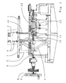
Fig. 1 zeigt ein zu prüfendes Bauteil 2, hier ein Zahnrad mit konischer Innenverzahnung, das auf einem Messtisch 1 angeordnet ist. Über eine Handkurbel 3 wird der Messtisch 1 mit Hilfe einer Anhebvorrichtung 4 , die hier nach dem Hubscherenprinzip arbeitet, auf die notwendige Messhöhe eingestellt. Der Hub des Messtisches 1 kann über ein Steigungslineal 5 an einer Messuhr 6 abgelesen werden. Der Tischhub kann weiterhin auf jede gewünschte Länge mittels Endanschlägen 7 eingestellt werden. Werden diese Endanschläge 7 angefahren, wird eine Rutschkupplung 8 aktiviert, die ein Überfahren der Endanschläge 7 verhindert. Das zu prüfende Bauteil 2 wird zwischen einem festen Messtaster 9 und einem beweglichen Messtaster 10 vorpositioniert. Durch Umlegen eines nicht dargestellten Hebels wird über eine Exzenterscheibe 13 der Messvorgang eingeleitet. Ein federbetätigter Mechanismus 14 drückt den beweglichen Messtaster 10 mit Hilfe einer Vorrichtung 15, die hier als Linearschlitten dargestellt ist, gegen das Bauteil 2 in Messposition. Die Messkraft des federbetätigten Mechanismus ist über eine Schraube 16 stufenlos einstellbar.Fig. 1 shows a component to be tested 2, here a gear with conical internal toothing, which is arranged on a measuring table 1. About a
Fig. 2 zeigt das zu prüfende Bauteil 2 auf dem Messtisch 1, das vorpositioniert zwischen dem festen Messtaster 9 und dem beweglichen Messtaster 10 liegt. Das Vorpositionieren wird durch reibungsverringernde Hilfsmittel 11, hier beispielsweise als Rollenkäfige dargestellt, erleichtert, die in dem Messtisch 1 integriert sind. Durch Umlegen eines Hebels 12 wird der eigentliche Messvorgang eingeleitet. Über die Exzenterscheibe 13 wird der federbetätigte Mechanismus 14 aktiv, der mit Hilfe der Federkraft den beweglichen Messtaster 10 in seine Messstellung positioniert. Die Federkraft kann stufenlos über ein Gewinde eingestellt und ggf. korrigiert werden. Der bewegliche Messtaster 10 drückt nach außen und bringt das Bauteil 2 in seine Messposition. Der bewegliche Messtaster 10 kann aufgrund seines aktiven Messweges die Innenkontur abfahren und die Verzahnung des Bauteiles 2 überprüfen. Dazu wird der bewegliche Messtaster 10 in seine Abhebstellung durch erneutes Umlegen des Hebels 12 gebracht, der Messtisch 2 mit Hilfe der Anhebvorrichtung 3 in jeweils verschiedene Messpositionen gebracht und der Messvorgang mehrmals durch wiederholtes Umlegen des Hebels 12 durch Anlegen und Abheben des beweglichen Messtasters 10 aktiviert.Fig. 2 shows the component to be tested 2 on the measuring table 1, which is prepositioned between the
- 11
- Messtischmeasuring table
- 22
- Bauteilcomponent
- 33
- Handkurbelwinch
- 44
- Anhebvorrichtungelevating device
- 55
- Steigungslinealpitch ruler
- 66
- Messuhrgauge
- 77
- Endanschlagend stop
- 88th
- Rutschkupplungslip clutch
- 99
- Fester MesstasterFixed probe
- 1010
- beweglicher Messtastermovable probe
- 1111
- Hilfsmittelaid
- 1212
- Hebellever
- 1313
- Exzenterscheibeeccentric
- 1414
- federbetätigter Mechanismusspring operated mechanism
- 1515
- Vorrichtungcontraption
- 1616
- Schraubescrew
Claims (7)
- The invention relates to a measuring device for measuring gearings and diameters on rotationally symmetrical components.(2) by means of a fixed caliper (9) and a movable caliper (10), with the component (2) being pressed against the fixed caliper (9) by the movable caliper (10) with the aid of a spring-actuated mechanism (14), which is activated by means of an auxiliary mechanism, and is thereby brought into a defined measuring position, characterized in that the auxiliary mechanism features a movable lever (12), which by means of an eccentric disk (13) puts the movable caliper (10) into its measuring position.
- A measuring device according to daim 1, characterized in that the component to be measured is guided to the calipers (9, 10) by means of a lifting device (4) which is connected to a measuring table (1).
- A measuring device according to daim 1, characterized in that the measuring table (1) features friction-reducing means (11) on its surface, with the aid of which the component (2) to be tested can be easily positioned.
- A measuring device according to daim 2, characterized in that the lifting device (4) features at least one end stop (7), with the aid of which a fixed lift can be set.
- A measuring device according to daim 4, characterized in that if the end stop (7) is overshot, a safety dutch (8) will be activated to prevent damage.
- A measuring device according to daim 2, characterized in that the lift of the lifting device (4) can be read on the gage (6) of an indinometer (5).
- A measuring device according to daim 2, characterized in that the movement of the lifting device (4) can be brought about manually or by power-assisted means.
Applications Claiming Priority (3)
| Application Number | Priority Date | Filing Date | Title |
|---|---|---|---|
| DE10244025A DE10244025A1 (en) | 2002-09-21 | 2002-09-21 | Measuring device for measuring gears and diameters in rotationally symmetrical components |
| DE10244025 | 2002-09-21 | ||
| PCT/EP2003/010202 WO2004028669A2 (en) | 2002-09-21 | 2003-09-13 | Measuring device for measuring gearing and diameters in rotationally symmetrical components |
Publications (2)
| Publication Number | Publication Date |
|---|---|
| EP1540269A2 EP1540269A2 (en) | 2005-06-15 |
| EP1540269B1 true EP1540269B1 (en) | 2007-03-21 |
Family
ID=31983979
Family Applications (1)
| Application Number | Title | Priority Date | Filing Date |
|---|---|---|---|
| EP03798162A Expired - Fee Related EP1540269B1 (en) | 2002-09-21 | 2003-09-13 | Measuring device for measuring gearing and diameters in rotationally symmetrical components |
Country Status (6)
| Country | Link |
|---|---|
| US (1) | US7134215B2 (en) |
| EP (1) | EP1540269B1 (en) |
| BR (1) | BRPI0314638B1 (en) |
| DE (2) | DE10244025A1 (en) |
| ES (1) | ES2283872T3 (en) |
| WO (1) | WO2004028669A2 (en) |
Families Citing this family (9)
| Publication number | Priority date | Publication date | Assignee | Title |
|---|---|---|---|---|
| DE102009002649B4 (en) | 2009-04-27 | 2011-06-22 | Feinmeß Suhl GmbH, 98527 | Gear measuring device for measuring a tooth width |
| JP5477642B2 (en) * | 2010-03-29 | 2014-04-23 | アイシン精機株式会社 | Gear shape measuring device |
| DE102010026891A1 (en) * | 2010-04-09 | 2011-10-13 | Stotz Feinmesstechnik Gmbh | Device for measuring objects |
| RU2471145C1 (en) * | 2011-08-03 | 2012-12-27 | Федеральное государственное бюджетное образовательное учреждение высшего профессионального образования "Южно-Уральский государственный университет" (национальный исследовательский университет) (ФГБОУ ВПО "ЮУрГУ" (НИУ)) | Method of controlling accuracy parameters of end faces of body of rotation type articles |
| DE102016200577A1 (en) | 2016-01-19 | 2017-07-20 | Zf Friedrichshafen Ag | Measuring device for measuring gears |
| US10288404B2 (en) * | 2016-04-06 | 2019-05-14 | Jtekt Corporation | Gear measurement method and gear measurement apparatus |
| RU179255U1 (en) * | 2018-01-18 | 2018-05-07 | Федеральное государственное казенное военное образовательное учреждение высшего образования "Военная академия материально-технического обеспечения имени генерала армии А.В. Хрулёва" Министерства обороны Российской Федерации | LINE OF OFFICER OF MATERIAL AND TECHNICAL SUPPORT |
| DE102019101030B3 (en) | 2019-01-16 | 2019-12-19 | Schaeffler Technologies AG & Co. KG | Measuring device and method for determining a spherical dimension |
| CN110940254B (en) * | 2019-09-12 | 2021-06-04 | 华南理工大学 | Gear pitch deviation measuring method and measuring tool thereof |
Family Cites Families (12)
| Publication number | Priority date | Publication date | Assignee | Title |
|---|---|---|---|---|
| US2561534A (en) * | 1948-11-29 | 1951-07-24 | John J Parker | Gauge for checking toothed machine elements, such as gears and splines |
| DE832500C (en) | 1949-10-11 | 1952-02-25 | Mahr Carl | Measuring device for external and internal threads |
| US2728144A (en) * | 1954-08-16 | 1955-12-27 | Nilsson Cage Co Inc | Apparatus |
| US2909844A (en) * | 1954-12-20 | 1959-10-27 | Klingelnberg Soehne Ferd | Gear tester |
| DE1218737B (en) | 1959-09-12 | 1966-06-08 | Johannes Perthen Dr Ing | Bore gauge |
| US3589018A (en) * | 1969-09-08 | 1971-06-29 | Illinois Tool Works | Support system for internal gear-checking apparatus |
| US3771229A (en) * | 1971-02-18 | 1973-11-13 | J Reef | Double acting gage |
| SE420866B (en) | 1977-11-14 | 1981-11-02 | Lars Osten Forsman | DEVICE INDICATOR INDICATOR |
| CH630174A5 (en) * | 1978-04-05 | 1982-05-28 | Hans Meyer | INTERIOR MEASURING DEVICE. |
| DE4418829C2 (en) * | 1993-08-06 | 1998-05-07 | Frenco Verzahnungslehren | Gear testing device |
| DE4326406C1 (en) * | 1993-08-06 | 1994-12-01 | Frenco Verzahnungslehren | Gear testing device (apparatus, set, instrument) |
| US6901676B1 (en) * | 2004-02-06 | 2005-06-07 | Honda Motor Co., Ltd. | Eccentric bushing inspection device |
-
2002
- 2002-09-21 DE DE10244025A patent/DE10244025A1/en not_active Withdrawn
-
2003
- 2003-09-13 WO PCT/EP2003/010202 patent/WO2004028669A2/en active IP Right Grant
- 2003-09-13 ES ES03798162T patent/ES2283872T3/en not_active Expired - Lifetime
- 2003-09-13 BR BRPI0314638A patent/BRPI0314638B1/en not_active IP Right Cessation
- 2003-09-13 EP EP03798162A patent/EP1540269B1/en not_active Expired - Fee Related
- 2003-09-13 DE DE50306865T patent/DE50306865D1/en not_active Expired - Lifetime
- 2003-09-13 US US10/527,477 patent/US7134215B2/en not_active Expired - Lifetime
Also Published As
| Publication number | Publication date |
|---|---|
| US20050262715A1 (en) | 2005-12-01 |
| BRPI0314638B1 (en) | 2016-11-01 |
| BR0314638A (en) | 2005-08-02 |
| WO2004028669A3 (en) | 2004-10-14 |
| US7134215B2 (en) | 2006-11-14 |
| DE50306865D1 (en) | 2007-05-03 |
| WO2004028669A2 (en) | 2004-04-08 |
| ES2283872T3 (en) | 2007-11-01 |
| DE10244025A1 (en) | 2004-04-08 |
| EP1540269A2 (en) | 2005-06-15 |
Similar Documents
| Publication | Publication Date | Title |
|---|---|---|
| EP2096424B1 (en) | Actuating device for testing torque wrenches | |
| EP0392188B1 (en) | Test device for a vehicle brake system | |
| DE3340227C2 (en) | Internal screw thread gauge | |
| DE102017117782B3 (en) | Alignment device for aligning a measuring aid of a test device | |
| DE202012011761U1 (en) | Device for checking a sprocket | |
| DE102013007535B3 (en) | Force-measuring device | |
| EP1540269B1 (en) | Measuring device for measuring gearing and diameters in rotationally symmetrical components | |
| DE10350085B4 (en) | Measuring device for an electro-mechanical brake | |
| DE202014006698U1 (en) | Device for checking the spherical dimension of the toothing of a workpiece | |
| DE202015106965U1 (en) | Measuring device for checking a chuck | |
| DE19961232C1 (en) | Chamfer angle measurer for chamfered bore has rail pivoted to end of measuring finger inserted in bore and contacted by measuring sensor coupled to measuring dial | |
| EP2892791B1 (en) | Method for measuring belt tension | |
| EP1001247A2 (en) | Position indicator for measuring the setting stroke way of the roll of a rolling frame | |
| DE3525864C1 (en) | Portable brake pressure test device | |
| DE102013111526A1 (en) | METHOD AND DEVICE FOR VALIDATING A MEASUREMENT DEVICE FOR A WHEEL SET OF A RAIL VEHICLE | |
| DE3544323A1 (en) | SCREWDRIVER WITH A MEASURING DEVICE FOR DETERMINING TRANSLATORY MOVEMENT | |
| DE102016200577A1 (en) | Measuring device for measuring gears | |
| DE202006019762U1 (en) | Device for measuring torques | |
| DE4014504C1 (en) | Screw thread depth measuring device - monitors limit marks w.r.t. scribed line on sliding barrel pressed into workface | |
| DE102018203259A1 (en) | Test device and method for testing components | |
| DE102004018692B4 (en) | Measuring device for determining the required thickness of a component | |
| DE102010054201A1 (en) | Method for functional testing of ball screw for steering system of motor vehicle, involves evaluating course of moment size within test interval to determine whether moment size is exceeded preset maximum value or threshold value | |
| DE3331014C2 (en) | Length measuring device, especially for measuring gauge blocks | |
| DE1915122C3 (en) | ||
| DE453567C (en) | Device for checking the tooth flanks of toothed wheels |
Legal Events
| Date | Code | Title | Description |
|---|---|---|---|
| PUAI | Public reference made under article 153(3) epc to a published international application that has entered the european phase |
Free format text: ORIGINAL CODE: 0009012 |
|
| 17P | Request for examination filed |
Effective date: 20041211 |
|
| AK | Designated contracting states |
Kind code of ref document: A2 Designated state(s): AT BE BG CH CY CZ DE DK EE ES FI FR GB GR HU IE IT LI LU MC NL PT RO SE SI SK TR |
|
| RBV | Designated contracting states (corrected) |
Designated state(s): DE ES FR HU |
|
| GRAP | Despatch of communication of intention to grant a patent |
Free format text: ORIGINAL CODE: EPIDOSNIGR1 |
|
| GRAS | Grant fee paid |
Free format text: ORIGINAL CODE: EPIDOSNIGR3 |
|
| GRAA | (expected) grant |
Free format text: ORIGINAL CODE: 0009210 |
|
| AK | Designated contracting states |
Kind code of ref document: B1 Designated state(s): DE ES FR HU |
|
| REF | Corresponds to: |
Ref document number: 50306865 Country of ref document: DE Date of ref document: 20070503 Kind code of ref document: P |
|
| REG | Reference to a national code |
Ref country code: HU Ref legal event code: AG4A Ref document number: E001588 Country of ref document: HU |
|
| ET | Fr: translation filed | ||
| REG | Reference to a national code |
Ref country code: ES Ref legal event code: FG2A Ref document number: 2283872 Country of ref document: ES Kind code of ref document: T3 |
|
| PLBE | No opposition filed within time limit |
Free format text: ORIGINAL CODE: 0009261 |
|
| STAA | Information on the status of an ep patent application or granted ep patent |
Free format text: STATUS: NO OPPOSITION FILED WITHIN TIME LIMIT |
|
| 26N | No opposition filed |
Effective date: 20071227 |
|
| PGFP | Annual fee paid to national office [announced via postgrant information from national office to epo] |
Ref country code: ES Payment date: 20150810 Year of fee payment: 13 |
|
| REG | Reference to a national code |
Ref country code: FR Ref legal event code: PLFP Year of fee payment: 14 |
|
| REG | Reference to a national code |
Ref country code: FR Ref legal event code: PLFP Year of fee payment: 15 |
|
| PG25 | Lapsed in a contracting state [announced via postgrant information from national office to epo] |
Ref country code: ES Free format text: LAPSE BECAUSE OF NON-PAYMENT OF DUE FEES Effective date: 20160914 |
|
| REG | Reference to a national code |
Ref country code: FR Ref legal event code: PLFP Year of fee payment: 16 |
|
| REG | Reference to a national code |
Ref country code: ES Ref legal event code: FD2A Effective date: 20181128 |
|
| PGFP | Annual fee paid to national office [announced via postgrant information from national office to epo] |
Ref country code: DE Payment date: 20190903 Year of fee payment: 17 Ref country code: FR Payment date: 20190815 Year of fee payment: 17 |
|
| PGFP | Annual fee paid to national office [announced via postgrant information from national office to epo] |
Ref country code: HU Payment date: 20190801 Year of fee payment: 17 |
|
| REG | Reference to a national code |
Ref country code: DE Ref legal event code: R119 Ref document number: 50306865 Country of ref document: DE |
|
| PG25 | Lapsed in a contracting state [announced via postgrant information from national office to epo] |
Ref country code: DE Free format text: LAPSE BECAUSE OF NON-PAYMENT OF DUE FEES Effective date: 20210401 Ref country code: FR Free format text: LAPSE BECAUSE OF NON-PAYMENT OF DUE FEES Effective date: 20200930 |
|
| PG25 | Lapsed in a contracting state [announced via postgrant information from national office to epo] |
Ref country code: HU Free format text: LAPSE BECAUSE OF NON-PAYMENT OF DUE FEES Effective date: 20200914 |