EP1539620B1 - Method and apparatus for grouping aseptic products - Google Patents
Method and apparatus for grouping aseptic products Download PDFInfo
- Publication number
- EP1539620B1 EP1539620B1 EP03755801A EP03755801A EP1539620B1 EP 1539620 B1 EP1539620 B1 EP 1539620B1 EP 03755801 A EP03755801 A EP 03755801A EP 03755801 A EP03755801 A EP 03755801A EP 1539620 B1 EP1539620 B1 EP 1539620B1
- Authority
- EP
- European Patent Office
- Prior art keywords
- product
- products
- conveyor
- selector
- lugs
- Prior art date
- Legal status (The legal status is an assumption and is not a legal conclusion. Google has not performed a legal analysis and makes no representation as to the accuracy of the status listed.)
- Expired - Lifetime
Links
- 238000000034 method Methods 0.000 title claims abstract description 11
- 238000004806 packaging method and process Methods 0.000 claims abstract description 49
- 238000012546 transfer Methods 0.000 claims description 14
- 239000011449 brick Substances 0.000 description 38
- 238000011144 upstream manufacturing Methods 0.000 description 8
- 239000000463 material Substances 0.000 description 4
- 239000011295 pitch Substances 0.000 description 4
- 239000000945 filler Substances 0.000 description 3
- 235000011389 fruit/vegetable juice Nutrition 0.000 description 3
- 239000011087 paperboard Substances 0.000 description 3
- 230000000712 assembly Effects 0.000 description 2
- 238000000429 assembly Methods 0.000 description 2
- 235000013361 beverage Nutrition 0.000 description 2
- 239000011888 foil Substances 0.000 description 2
- 230000007246 mechanism Effects 0.000 description 2
- 238000000926 separation method Methods 0.000 description 2
- 229920004943 Delrin® Polymers 0.000 description 1
- 239000004677 Nylon Substances 0.000 description 1
- 238000007792 addition Methods 0.000 description 1
- 239000013590 bulk material Substances 0.000 description 1
- 230000008859 change Effects 0.000 description 1
- 239000011248 coating agent Substances 0.000 description 1
- 238000000576 coating method Methods 0.000 description 1
- 230000006835 compression Effects 0.000 description 1
- 238000007906 compression Methods 0.000 description 1
- 238000007796 conventional method Methods 0.000 description 1
- 230000001419 dependent effect Effects 0.000 description 1
- 239000007788 liquid Substances 0.000 description 1
- 238000012986 modification Methods 0.000 description 1
- 230000004048 modification Effects 0.000 description 1
- 229920001778 nylon Polymers 0.000 description 1
- 239000004033 plastic Substances 0.000 description 1
- 238000012552 review Methods 0.000 description 1
- 239000003566 sealing material Substances 0.000 description 1
- 230000000087 stabilizing effect Effects 0.000 description 1
- 230000007704 transition Effects 0.000 description 1
Images


Classifications
-
- B—PERFORMING OPERATIONS; TRANSPORTING
- B65—CONVEYING; PACKING; STORING; HANDLING THIN OR FILAMENTARY MATERIAL
- B65G—TRANSPORT OR STORAGE DEVICES, e.g. CONVEYORS FOR LOADING OR TIPPING, SHOP CONVEYOR SYSTEMS OR PNEUMATIC TUBE CONVEYORS
- B65G47/00—Article or material-handling devices associated with conveyors; Methods employing such devices
- B65G47/52—Devices for transferring articles or materials between conveyors i.e. discharging or feeding devices
- B65G47/68—Devices for transferring articles or materials between conveyors i.e. discharging or feeding devices adapted to receive articles arriving in one layer from one conveyor lane and to transfer them in individual layers to more than one conveyor lane or to one broader conveyor lane, or vice versa, e.g. combining the flows of articles conveyed by more than one conveyor
- B65G47/71—Devices for transferring articles or materials between conveyors i.e. discharging or feeding devices adapted to receive articles arriving in one layer from one conveyor lane and to transfer them in individual layers to more than one conveyor lane or to one broader conveyor lane, or vice versa, e.g. combining the flows of articles conveyed by more than one conveyor the articles being discharged or distributed to several distinct separate conveyors or to a broader conveyor lane
- B65G47/715—Devices for transferring articles or materials between conveyors i.e. discharging or feeding devices adapted to receive articles arriving in one layer from one conveyor lane and to transfer them in individual layers to more than one conveyor lane or to one broader conveyor lane, or vice versa, e.g. combining the flows of articles conveyed by more than one conveyor the articles being discharged or distributed to several distinct separate conveyors or to a broader conveyor lane to a broader conveyor lane
-
- B—PERFORMING OPERATIONS; TRANSPORTING
- B65—CONVEYING; PACKING; STORING; HANDLING THIN OR FILAMENTARY MATERIAL
- B65B—MACHINES, APPARATUS OR DEVICES FOR, OR METHODS OF, PACKAGING ARTICLES OR MATERIALS; UNPACKING
- B65B35/00—Supplying, feeding, arranging or orientating articles to be packaged
- B65B35/30—Arranging and feeding articles in groups
- B65B35/40—Arranging and feeding articles in groups by reciprocating or oscillatory pushers
- B65B35/405—Arranging and feeding articles in groups by reciprocating or oscillatory pushers linked to endless conveyors
-
- B—PERFORMING OPERATIONS; TRANSPORTING
- B65—CONVEYING; PACKING; STORING; HANDLING THIN OR FILAMENTARY MATERIAL
- B65G—TRANSPORT OR STORAGE DEVICES, e.g. CONVEYORS FOR LOADING OR TIPPING, SHOP CONVEYOR SYSTEMS OR PNEUMATIC TUBE CONVEYORS
- B65G47/00—Article or material-handling devices associated with conveyors; Methods employing such devices
- B65G47/02—Devices for feeding articles or materials to conveyors
- B65G47/04—Devices for feeding articles or materials to conveyors for feeding articles
- B65G47/06—Devices for feeding articles or materials to conveyors for feeding articles from a single group of articles arranged in orderly pattern, e.g. workpieces in magazines
- B65G47/08—Devices for feeding articles or materials to conveyors for feeding articles from a single group of articles arranged in orderly pattern, e.g. workpieces in magazines spacing or grouping the articles during feeding
- B65G47/084—Devices for feeding articles or materials to conveyors for feeding articles from a single group of articles arranged in orderly pattern, e.g. workpieces in magazines spacing or grouping the articles during feeding grouping articles in a predetermined 2-dimensional pattern
- B65G47/086—Devices for feeding articles or materials to conveyors for feeding articles from a single group of articles arranged in orderly pattern, e.g. workpieces in magazines spacing or grouping the articles during feeding grouping articles in a predetermined 2-dimensional pattern cubiform articles
-
- B—PERFORMING OPERATIONS; TRANSPORTING
- B65—CONVEYING; PACKING; STORING; HANDLING THIN OR FILAMENTARY MATERIAL
- B65G—TRANSPORT OR STORAGE DEVICES, e.g. CONVEYORS FOR LOADING OR TIPPING, SHOP CONVEYOR SYSTEMS OR PNEUMATIC TUBE CONVEYORS
- B65G47/00—Article or material-handling devices associated with conveyors; Methods employing such devices
- B65G47/74—Feeding, transfer, or discharging devices of particular kinds or types
- B65G47/84—Star-shaped wheels or devices having endless travelling belts or chains, the wheels or devices being equipped with article-engaging elements
- B65G47/841—Devices having endless travelling belts or chains equipped with article-engaging elements
Definitions
- the present invention relates to a method of grouping products for packaging and to a system for grouping aseptic products for packaging. More generally, it relates to product packaging systems, and in particular to a method and system for metering, selecting, and grouping aseptic products for packaging by an automated packaging machine.
- aseptic bricks or packages have become a popular alternative to conventional beverage packaging such as bottles and cans.
- Such aseptic brick packages typically include juice boxes or pouches in which a foil or paperboard tube or sleeve is filled with a liquid beverage or other bulk material and its ends sealed to form a light-weight, disposable container.
- these aseptic bricks or containers are packaged in groups such as four packs, six packs, eight packs, ten packs, etc., in which the bricks are placed side by side in rows of two to four bricks and are shrink wrapped or otherwise banded together for sale.
- the packaging or aseptic bricks in groups is, however, subject to significant problems, given the generally square or rectangular configuration of the aseptic bricks and the use of paperboard or other similar materials therefor which are compressible, as opposed to more rigid cans and bottles, and which generally are coated with a wax sealing material.
- One conventional method of grouping such aseptic bricks for packaging has been to cycle the aseptic bricks forwardly in a line to an end-point, whereupon a pusher will engage and push a series or group of bricks, i.e., three, four or five bricks, onto a packaging line.
- the line of aseptic bricks is then cycled forwardly again and a next grouping of bricks is engaged and pushed onto the packaging line to form a six, eight or ten pack.
- Other packaging systems have involved the use of feed screws to engage and create gaps between the aseptic bricks and urge groups or sets of bricks in series into an input position for a packaging machine line.
- This prior art apparatus includes a conveyor for moving a single row of articles in contacting relation with each other, a plurality of shuttle elements movable alongside the articles at a velocity less than the conveyor velocity and slidable in a direction transverse thereto, the shuttle elements being engageable respectively with a leading part of an article so as temporarily to control the velocity thereof, shuttle withdrawing cams engageable in sequence with the shuttles to impart transverse movement thereto in a direction away from the articles together with a stabilizing element engageable with the articles for preventing rotary movement thereof during shuttle withdrawal movement.
- the products are then spaced with respect to one another by sequentially accelerating the products by the conveyor when they are released from the shuttle elements.
- the articles are grouped in that the first article in each group bounces a flight bar moving at a less speed than the conveyor, and the remaining articles of the respective group pile up behind the first article.
- the present invention relates to a product grouping and method system for metering, selecting and forming groups of products such as "aseptic bricks" for introduction of the groups into a product packaging machine to form four packs, six packs, eight packs, ten packs and/or other varying product package configurations.
- the products will be received from an upstream filler assembly along an input section of a product conveyor with the products being moved along a path of travel substantially in end-to-end abutment with one another.
- the products enter the product grouping system of the present invention, they pass through a metering station wherein the line of products is engaged from opposite sides by a pair or metering units.
- Each of the metering units generally includes a metering lug conveyor that extends substantially parallel to the path of travel of the products and includes a series of spaced metering lugs.
- Each metering lug generally has a forward, proximal engaging portion and a rearward, distal section or portion attached to its lug conveyor.
- the metering units each further include a pair of cam plates having a cam track defined therein. First and second cam followers attached to each of the metering lugs engage and ride along the cam tracks of the cam plates so that the metering lugs of each metering unit are moved into engagement with alternating ones of the line of products moving along the product conveyor.
- the metering lugs typically urge the products into offset positions that are offset from a centerline of the line of products by an amount slightly greater than one-half a brick or product width, such that the products are divided into at least two separate lanes for continued movement along the product conveyor.
- the selector station generally includes a pair of opposed selector units mounted along one of the multiple lanes of the product conveyor.
- Each of the selector units generally includes a lug conveyor having a series of spaced selector lugs.
- the selector lugs of each selector unit are mounted along their respective lug conveyors at different pitches.
- the selector lugs of a first one of the selector units also are moved at a first rate or speed, while the selector lugs of the second selector unit are moved at a second speed or rate that is different from the rate of the selector lugs of the first selector unit.
- Figs. 1 - 6D generally illustrate the product grouping system 10 of the present invention.
- the product grouping system 10 ( Figs. 1 and 2 ) is adapted to select and form groups 11 of products 12 for introduction or transfer of the products in their selected groups 11 to an inlet or in-feed conveyor 13 of a downstream product packaging machine (not shown).
- the products 12 generally will be grouped into a series of 2, 3, 4, 5 or more products, typically received at the in-feed conveyor 13 of the product packaging machine in an aligned, side by side, arrangement with another group 11' ( Fig.
- the product grouping system of the present invention is especially suited for packaging square, rectangular or other flat sided products, such as "aseptic bricks", such as juice boxes, juice pouches, or other product containers constructed from a foil or paperboard material, which products are generally compressible. It will be understood, however, that the present invention is not limited simply to the packaging of aseptic bricks, but also can be used for grouping other types of products for packaging.
- the products 12 will be received from an upstream filler assembly or system (not shown), conveyed along a product conveyor 14 with the products being moved along a path of travel indicated by arrow 16.
- the products generally will be received in a single line in substantially an end-to-end abutment with one another.
- the product conveyor 14 generally includes an upstream, input or first section 17 along which the single line of products 12 is introduced into the product grouping system 10, and a second or grouping section 18 along which the products are separated into multiple lanes of products, indicated by 19 and 19', and arranged into the selected groups of products 11 at a discharge or transfer point or end 20 for transfer to the in-feed conveyor 13 of the product packaging machine.
- the product conveyor 14 generally includes an Intralox belt having a series of spaced, raised ribs 21 on which the products are supported.
- a transfer plate or dead plate 22 is between the input and grouping sections of the product conveyor and between the discharge or transfer point 20 of the conveyor and the in-feed conveyor 13 of the product packaging machine. The products thus are able to make a smooth transition from one section of the product conveyor to the next and to the in-feed conveyor 13.
- Each of the sections of the product conveyor generally are driven by a variable speed drive motor to enable the speed of the products traveling along the product conveyor to be varied as needed to maintain a desired back pressure between the products being received from the filling assembly to avoid gaps or increased compression between the products.
- each of the metering units 26 and 27 generally includes a metering lug conveyor 28 that extends along an elliptical path substantially parallel to the line of products moving along the product conveyor.
- the metering lug conveyors 28 generally include belts, chains or other, similar conveying elements and have a series of spaced metering lugs 29 mounted along the length thereof.
- Each metering lug 29 is typically is formed from a plastic material, such as nylon, Delrin or other similar lightweight, durable, non-stick material, and includes a forward proximal engaging portion 31 and a rearward distal section or portion 32 that typically extends horizontally and is attached to its lug conveyor 28.
- the forward engaging portions of each of the metering lugs generally are substantially rectangular with a substantially flat front or forward face or surface 33, and typically are of a width substantially equal to or less than the width of the products 12 moving along the product conveyor. As further indicated in Fig.
- the rearward distal portions of the metering lugs each generally have outwardly flared or laterally extending projections 34 and 36.
- a connector pin or first cam follower 37 is attached to one of the projections 34 of each metering lug and connects to the lug conveyor 28 so that the metering lugs are moved or carried with the lug conveyor toward and away from engagement with the products as indicated in Figs. 6A .
- each of the metering units 26 and 27 further generally includes a pair of stacked, opposed cam plates 38 and 39.
- Each of the cam plates 38 and 39 generally includes a cam track or guide track 41 or 42, respectively.
- the lug conveyor 28 and first cam follower 37 of each of the metering lugs is received and moves along the upper or first cam track 41 formed in the upper cam plate 38 so as to accordingly guide the metering lugs about their path of travel into and out of engagement with the products 12, as indicated by arrows 43 and 44 in Fig. 6A .
- a second cam follower 46 is attached to the lower or underside portions of the second projections 36 of each of the metering lugs 29, as indicated in Fig. 5 and 6 , which second cam follower 46 is received and moves along the second cam track 42 formed in the lower cam plate 39.
- the movement of the second cam follower 46 along its cam track 42 causes the metering lugs to be pivoted and thus aligned substantially parallel with the side surfaces of the products 12, as indicated in Figs. 1 , 5 and 6A - 6B , so that as the metering lugs are moved in the direction of arrows 43 and 44 ( Figs. 6A and 6B ) the front surfaces 33 of their forward engaging portions 31 are aligned substantially parallel with the products so as to substantially fully engage the flat surfaces of the products to urge the products across the product conveyor and into one of the lanes of the product conveyor.
- each lug conveyor 28 of each metering station is extended about a drive sprocket 47 and an idler sprocket 48, with the drive sprockets 47 each being connected to a drive shaft 49 ( Fig. 3 ) that is linked to a drive motor 51.
- the drive motors generally drive the lug conveyors at speeds approximately equivalent to the speed or rate at which the products 12 are being moved along their path of travel 16, along the product conveyor.
- the metering lugs generally are spaced or pitched along their lug conveyors approximately equivalent to the movement of the products being conveyed along the product conveyor so that each of the metering lugs is product pitched, with the metering lugs of the opposed metering units engaging alternate ones of the products.
- the product conveyors can be adjusted by adjusting the position of their idler sprockets 48 via an adjustment slot 52 ( Fig. 5 ) formed in lower cam plate 39.
- the metering lugs of each of the metering stations generally engage alternating ones of the products 12 as the products are being transitioned from the input or in-feed section 17 of the product conveyor to the intermediate section 18.
- the metering lugs engage their respective products, the metering lugs are moved in a direction normal to the products, as indicated by arrow 44, while at the same time are moved in a substantially parallel alignment with the products in the direction of arrow 43 ( Fig. 6B ).
- the products are urged laterally across the product conveyor into the different lanes 19 and 19' of the product conveyor.
- the products generally are shifted across the product conveyor by an amount slightly greater than the width or thickness of the products being conveyed so as to create a slight separation between the products.
- a guide plate 53 is received between the lanes of products so as to maintain the products in their separate lanes.
- the forward or proximal end of the guide plate 53 generally is formed with a cut-out portion 54 ( Fig. 6B and 6C ) which enables the metering lugs to complete their motion for urging their selected products into one of the product lanes on the product conveyor and thereafter can be pivoted out of engagement with the products as the products are moved along the guide plate so as to not interfere with the operation of the metering lugs.
- a selector station 60 ( Fig. 1 ) is positioned downstream from the metering station 25, extending along the second or grouping portion 18 of the product conveyor 14 from a position adjacent the upstream dead-plate or transfer plate 22 through the transfer or discharge point 20 between the product conveyor 14 and in-feed conveyor 13 for the product packaging machine.
- the selector station 60 includes a pair of opposed selector units 61 and 62 positioned on opposite sides of the product conveyor 14 along one of the lanes 19 or 19' thereof.
- Each selector unit 61 and 62 generally includes selector conveyor, which can be a chain, belt or similar conveyor that extends about a substantially elliptical path about an upstream idler sprocket 64 to a downstream drive sprocket 66.
- selector conveyor can be a chain, belt or similar conveyor that extends about a substantially elliptical path about an upstream idler sprocket 64 to a downstream drive sprocket 66.
- Each of the drive sprockets 66 is driven by a variable speed drive, indicated at 67 in Fig. 4 , with the selector conveyor 63 of selector unit 62 being driven at a slightly greater rate than the selector conveyor of selector unit 61.
- a series of selector lugs 68 are mounted to the lug conveyors of each of the selector units 61 and 62.
- the selector lugs of the selector units 61 and 62 generally are mounted at different spacings or pitches, based upon the overall rate at which the products are being packaged by the downstream packaging machine and the rate at which the products are being input into the product grouping system 10.
- the selector lugs 68 of the conveyor 63 of selector unit 62 will be at a greater pitch or spacing than the lug conveyor of selector unit 61, but the lug conveyor of selector unit 62 also generally will be operated at a first rate that is faster than a second rate at which the lug conveyor of selector unit 61 is operated.
- the rates of movement or operation of the lug conveyors of selector units 61 and 62 further are greater than the rate at which the products themselves are being moved along the lanes 19 and 19' of the product conveyor.
- each of the selector lugs 68 generally is substantially triangularly shaped with a substantially flat, forward pushing edge 69.
- Each selector lug generally is pivotally attached to its lug conveyor 63 by a pivot pin 71 so that the selector lugs can be pivoted from a retracted, non-engaging position to a forwardly extending, engaging position for engaging and urging the products along the grouping section 18 of the product conveyor 14, as indicated in Figs. 1 and 6B - 6D .
- Guide rails 72 generally are mounted along the path of travel of each of the lug conveyor of each selector unit, positioned adjacent and extending substantially parallel to the lanes of the product conveyor 14.
- the selector lugs engage and ride along the guide rails as they are pivoted around the upstream idler sprockets 64, so that the selector lugs are pivoted into their forwardly extending engaging position to engage the products.
- the guide rails are tapered or sloped toward an end point 73, such that the selector lugs are allowed to pivot toward their non-engaging positions as they are pulled further forwardly against the rear surfaces of the products.
- Each of the groups 11 of products formed by the selector units 61 and 62 are received at the discharge or transfer point 20 between the product conveyor 14 and in-feed conveyor 13 of a product packaging machine, with the groups of each lane aligned in a substantially parallel arrangement to form a product package, such as a four-pack, eight-pack, ten-pack or other arrangement as indicated in Fig. 1 .
- a line of products 12 generally is conveyed from an upstream product filling assembly or machine (not shown) along a product conveyor 14.
- the products generally are introduced into the product grouping system in a substantially single line of products being moved along a path of travel 16 along input section 17 ( Fig. 1 ) of the product conveyor 14.
- the products are transitioned between the input section 17 of the product conveyor 14 and the second or grouping section 18 of the product conveyor, they are passed over a transfer plate 22 and are initially engaged by a series of metering lugs 29 of a pair of opposed metering units 26 and 27.
- the metering lugs are product pitched and generally are moving at substantially the same rate as the products are moving along the product conveyor.
- the metering lugs are conveyed along their path of travel parallel to the line of products in the direction of arrow 43, they are also moved in a direction normal to the line of products, as indicated by arrows 44, so that the metering lugs are progressively moved into engagement with and subsequently urge the products laterally across the product conveyor into offset positions, offset from a centerline of the line of products being input to the product grouping system by an amount slightly greater than the width or thickness of each product.
- cam followers 46 attached to underside portions of each of the metering lugs 29 are moved along a lower or second cam track 42, which causes the metering lugs to be pivoted with respect to the product.
- the forward engaging portions 31 of the metering lugs accordingly are oriented and maintained substantially parallel to the sides of the products as they engage and urge the products across the product conveyor.
- the products are segregated or separated into multiple lanes 19 and 19' ( Figs. 1 and 6B - 6C ) of products, with each product typically separated by approximately one product length.
- the separated lanes of products are moved out of the metering station, they are transitioned into a selector station 60, wherein selected products of each of the lanes 19 and 19' of products 12 are engaged by the selector lugs 68 of a pair of opposed selector units 61 and 62 ( Fig. 1 ).
- the pitch of the selector lugs of each unit generally is spaced dependent upon the rate at which the products are being fed into the product grouping system from the filling station or mechanism, the number of products to be grouped, and the rate at which the product packaging machine is packaging the groups of products.
- the selector lugs of each of the selector units 61 and 62 are moved into engagement with a selected one of a series of products moving along the multiple lanes of the product conveyor through the selector station, i.e., the selector lugs will engage every third, fourth, or fifth product, depending upon the size of the product groups, i.e., three, four, or five, to be formed.
- the selector lugs of each of the selector units also generally are moved at different rates, each of which are slightly faster than the rate at which the products are being moved along the product conveyor so that each of the products in the selected group of products will catch up to their immediately preceding products to form a group of products that are aligned in a substantially end-to-end abutting relationship, as indicated in Figs. 1 and 6D .
- the selector lugs of the selector unit 62 ( Fig.1 ) will be moved at a slightly greater rate than the selector lugs of selector unit 61 so that the group of products formed by selector unit 62 will also catch up to and be aligned with a corresponding group of products formed by selector unit 61.
- the groups of products are presented in a substantially parallel alignment at the discharge or transfer point 20 between the product conveyor 14 of the product grouping system 10 and in-feed conveyor 13 of the downstream packaging machine so that the groups are formed into a desired product package arrangement, i.e., a four-pack, six-pack, eight-pack, ten-pack, or other arrangement.
Landscapes
- Engineering & Computer Science (AREA)
- Mechanical Engineering (AREA)
- Attitude Control For Articles On Conveyors (AREA)
- Auxiliary Devices For And Details Of Packaging Control (AREA)
- Container Filling Or Packaging Operations (AREA)
- Wrapping Of Specific Fragile Articles (AREA)
- Seasonings (AREA)
- Package Frames And Binding Bands (AREA)
Abstract
Description
- The present invention relates to a method of grouping products for packaging and to a system for grouping aseptic products for packaging. More generally, it relates to product packaging systems, and in particular to a method and system for metering, selecting, and grouping aseptic products for packaging by an automated packaging machine.
- In recent years, so-called "aseptic bricks" or packages have become a popular alternative to conventional beverage packaging such as bottles and cans. Such aseptic brick packages typically include juice boxes or pouches in which a foil or paperboard tube or sleeve is filled with a liquid beverage or other bulk material and its ends sealed to form a light-weight, disposable container. Typically, these aseptic bricks or containers are packaged in groups such as four packs, six packs, eight packs, ten packs, etc., in which the bricks are placed side by side in rows of two to four bricks and are shrink wrapped or otherwise banded together for sale. The packaging or aseptic bricks in groups is, however, subject to significant problems, given the generally square or rectangular configuration of the aseptic bricks and the use of paperboard or other similar materials therefor which are compressible, as opposed to more rigid cans and bottles, and which generally are coated with a wax sealing material. As a result, as the aseptic bricks are conveyed to a conventional product packaging system, they tend to become tightly compacted or compressed together in an end-to-end abutting arrangement. Since their sides or ends are generally flat, there typically are little or no gaps between the aseptic bricks where conventional selectors, such as star wheels and the like, can engage and separate or segregate the products into groups or sets for packaging, as is the case with bottles or cans.
- One conventional method of grouping such aseptic bricks for packaging has been to cycle the aseptic bricks forwardly in a line to an end-point, whereupon a pusher will engage and push a series or group of bricks, i.e., three, four or five bricks, onto a packaging line. The line of aseptic bricks is then cycled forwardly again and a next grouping of bricks is engaged and pushed onto the packaging line to form a six, eight or ten pack. Other packaging systems have involved the use of feed screws to engage and create gaps between the aseptic bricks and urge groups or sets of bricks in series into an input position for a packaging machine line. However, the wax coating typically applied to most aseptic brick packages tends to create drag as the aseptic bricks are pushed along by the screw threads, which generally afford only limited, point-to-point contact, and can therefore lead to product misfeeds and jamming of the packaging line. In addition, most conventional aseptic brick packaging systems generally are run at significantly lower speeds than the filler equipment for the aseptic bricks, which consequently must be run at a slower rate so as to reduce the amount of product backflow and prevent jamming of the flow of products into the aseptic brick packaging machines. As a result, there typically must be at least one dedicated brick-packaging machine for each aseptic brick filling system or station.
- In addition, the size and waxy surfaces of some types of aseptic bricks can lead to problems with control of the bricks, especially when there is a change in velocity of the movement of the aseptic bricks, such as when a line is stopped and restarted, or as the speed of the bricks is increased so as to try to create gaps or spaces between the bricks to enable engagement by selector devices. This can result in tipping of especially tall bricks, which problem is further compounded by the drag exerted by the waxy surfaces of the bricks and a limited engagement of the bricks by most conventional selector mechanisms. These problems apply e.g. for the apparatus for arranging articles in groups disclosed in
US 4,577,745 A . This prior art apparatus includes a conveyor for moving a single row of articles in contacting relation with each other, a plurality of shuttle elements movable alongside the articles at a velocity less than the conveyor velocity and slidable in a direction transverse thereto, the shuttle elements being engageable respectively with a leading part of an article so as temporarily to control the velocity thereof, shuttle withdrawing cams engageable in sequence with the shuttles to impart transverse movement thereto in a direction away from the articles together with a stabilizing element engageable with the articles for preventing rotary movement thereof during shuttle withdrawal movement. In both product lanes produced thereby, the products are then spaced with respect to one another by sequentially accelerating the products by the conveyor when they are released from the shuttle elements. In the downstream selector station the articles are grouped in that the first article in each group bounces a flight bar moving at a less speed than the conveyor, and the remaining articles of the respective group pile up behind the first article. - A more or less similar system is known from
US 3,469,673 , the main differences to the prior art discussed being that grouping of the products takes place already in the metering station. To this end, the shuttle elements push groups of three articles alternatively to the first and the second product lane. The product groups leaving the metering station are handed over to pusher bar assemblies. The pusher bars of the two assemblies run at differenct speeds so as to laterally align the groups on the first and the second product lane for subsequent packaging. - From the above discussion, it can be seen that a need exists for a method and system for metering and selecting asptic bricks forsegregation of the bricks into product groups for introduction into a product packaging machine that enables the packaging of such aseptic bricks at increased rates and which addresses these and other related problems in the art.
- The object set out above is achieved by the method of grouping products for packaging as defined in claim 1 and by the system for grouping aseptic products as defined in claim 5, respectively. Briefly described, the present invention relates to a product grouping and method system for metering, selecting and forming groups of products such as "aseptic bricks" for introduction of the groups into a product packaging machine to form four packs, six packs, eight packs, ten packs and/or other varying product package configurations. Typically, the products will be received from an upstream filler assembly along an input section of a product conveyor with the products being moved along a path of travel substantially in end-to-end abutment with one another. As the products enter the product grouping system of the present invention, they pass through a metering station wherein the line of products is engaged from opposite sides by a pair or metering units.
- Each of the metering units generally includes a metering lug conveyor that extends substantially parallel to the path of travel of the products and includes a series of spaced metering lugs. Each metering lug generally has a forward, proximal engaging portion and a rearward, distal section or portion attached to its lug conveyor. The metering units each further include a pair of cam plates having a cam track defined therein. First and second cam followers attached to each of the metering lugs engage and ride along the cam tracks of the cam plates so that the metering lugs of each metering unit are moved into engagement with alternating ones of the line of products moving along the product conveyor. The metering lugs typically urge the products into offset positions that are offset from a centerline of the line of products by an amount slightly greater than one-half a brick or product width, such that the products are divided into at least two separate lanes for continued movement along the product conveyor.
- As the products are divided into multiple lanes across the product conveyor, they move into a selector station wherein the products are collected into sets or groups for discharge to the in-feed line of a product packaging station or machine. The selector station generally includes a pair of opposed selector units mounted along one of the multiple lanes of the product conveyor. Each of the selector units generally includes a lug conveyor having a series of spaced selector lugs. The selector lugs of each selector unit are mounted along their respective lug conveyors at different pitches. The selector lugs of a first one of the selector units also are moved at a first rate or speed, while the selector lugs of the second selector unit are moved at a second speed or rate that is different from the rate of the selector lugs of the first selector unit.
- As the products are moved along their separate lanes through the selector station, selected ones of the products of each lane are engaged by the selector lugs of the opposed selector units, which urge the products forwardly along their path of travel at the first and second rates. These rates further generally are greater than the rate at which the products are being conveyed by the product conveyor so that the products of each selected group will tend to catch up to immediately preceding products to form a group of two, three, four or more abutting products in each product lane at a transfer point at the downstream end of the product grouping system of the present invention for transfer to an in-feed conveyor for the downstream product packaging machine or system.
- Various objects, features and advantages of the present invention will become apparent to those skilled in the art upon a review of the following detailed description, when taken in conjunction with the accompanying drawings.
-
-
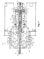
Fig. 1 is a plan view of the product grouping system of the present invention. -
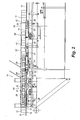
Fig. 2 is a side elevational view of the product grouping system of the present invention. -
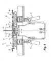
Fig. 3 is a cross-sectional view taken along lines 3 - 3 ofFig. 1 of the product grouping system of the present invention. -
Fig. 4 is a cross-sectional view taken along lines 4 - 4 ofFig. 1 of the product grouping system of the present invention. -
Fig. 5 is an exploded perspective view illustrating the cam tracks and movement of the metering lugs. -
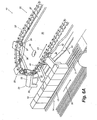
Figs. 6A-6D are a series of perspective views illustrating the operation of the product grouping system of the present invention showing the engagement and separation of the line of products by the metering and selector units for forming selected groups of products for packaging. - Referring now to the drawings in greater detail in which like numerals indicate like parts throughout the several views,
Figs. 1 - 6D generally illustrate theproduct grouping system 10 of the present invention. The product grouping system 10 (Figs. 1 and2 ) is adapted to select and formgroups 11 ofproducts 12 for introduction or transfer of the products in their selectedgroups 11 to an inlet or in-feed conveyor 13 of a downstream product packaging machine (not shown). Theproducts 12 generally will be grouped into a series of 2, 3, 4, 5 or more products, typically received at the in-feed conveyor 13 of the product packaging machine in an aligned, side by side, arrangement with another group 11' (Fig. 1 ) of products in order to form four-packs, six-packs, eight-packs, 10-packs and/or other varying product configurations for packaging. The product grouping system of the present invention is especially suited for packaging square, rectangular or other flat sided products, such as "aseptic bricks", such as juice boxes, juice pouches, or other product containers constructed from a foil or paperboard material, which products are generally compressible. It will be understood, however, that the present invention is not limited simply to the packaging of aseptic bricks, but also can be used for grouping other types of products for packaging. - Typically, the
products 12 will be received from an upstream filler assembly or system (not shown), conveyed along aproduct conveyor 14 with the products being moved along a path of travel indicated byarrow 16. The products generally will be received in a single line in substantially an end-to-end abutment with one another. As indicated inFig. 1 , theproduct conveyor 14 generally includes an upstream, input orfirst section 17 along which the single line ofproducts 12 is introduced into theproduct grouping system 10, and a second orgrouping section 18 along which the products are separated into multiple lanes of products, indicated by 19 and 19', and arranged into the selected groups ofproducts 11 at a discharge or transfer point orend 20 for transfer to the in-feed conveyor 13 of the product packaging machine. - As indicated in
Figs. 1 ,3 ,4 , and6A - 6D , theproduct conveyor 14 generally includes an Intralox belt having a series of spaced, raisedribs 21 on which the products are supported. A transfer plate ordead plate 22 is between the input and grouping sections of the product conveyor and between the discharge ortransfer point 20 of the conveyor and the in-feed conveyor 13 of the product packaging machine. The products thus are able to make a smooth transition from one section of the product conveyor to the next and to the in-feed conveyor 13. Each of the sections of the product conveyor generally are driven by a variable speed drive motor to enable the speed of the products traveling along the product conveyor to be varied as needed to maintain a desired back pressure between the products being received from the filling assembly to avoid gaps or increased compression between the products. - As illustrated in
Figs. 1 and2 , as the line ofproducts 12 enters the upstream end of theproduct grouping system 10 along theinput section 17 of theproduct conveyor 14, the products are passed through ametering station 25, wherein the line of products generally is engaged from opposite sides by a pair ofopposed metering units metering units separate lanes 19 and 19' of theproduct conveyor 14. As indicated inFigs. 1 ,5 and6A , each of themetering units metering lug conveyor 28 that extends along an elliptical path substantially parallel to the line of products moving along the product conveyor. - The
metering lug conveyors 28 generally include belts, chains or other, similar conveying elements and have a series of spaced metering lugs 29 mounted along the length thereof. Eachmetering lug 29 is typically is formed from a plastic material, such as nylon, Delrin or other similar lightweight, durable, non-stick material, and includes a forwardproximal engaging portion 31 and a rearward distal section orportion 32 that typically extends horizontally and is attached to itslug conveyor 28. The forward engaging portions of each of the metering lugs generally are substantially rectangular with a substantially flat front or forward face orsurface 33, and typically are of a width substantially equal to or less than the width of theproducts 12 moving along the product conveyor. As further indicated inFig. 5 , the rearward distal portions of the metering lugs each generally have outwardly flared or laterally extendingprojections Fig. 6A , a connector pin orfirst cam follower 37 is attached to one of theprojections 34 of each metering lug and connects to thelug conveyor 28 so that the metering lugs are moved or carried with the lug conveyor toward and away from engagement with the products as indicated inFigs. 6A . - As indicated in
Figs. 3 and5 , each of themetering units cam plates cam plates track Figs. 3 and5 , thelug conveyor 28 andfirst cam follower 37 of each of the metering lugs is received and moves along the upper orfirst cam track 41 formed in theupper cam plate 38 so as to accordingly guide the metering lugs about their path of travel into and out of engagement with theproducts 12, as indicated byarrows Fig. 6A . Asecond cam follower 46 is attached to the lower or underside portions of thesecond projections 36 of each of the metering lugs 29, as indicated inFig. 5 and6 , whichsecond cam follower 46 is received and moves along thesecond cam track 42 formed in thelower cam plate 39. The movement of thesecond cam follower 46 along itscam track 42 causes the metering lugs to be pivoted and thus aligned substantially parallel with the side surfaces of theproducts 12, as indicated inFigs. 1 ,5 and6A - 6B , so that as the metering lugs are moved in the direction ofarrows 43 and 44 (Figs. 6A and6B ) the front surfaces 33 of theirforward engaging portions 31 are aligned substantially parallel with the products so as to substantially fully engage the flat surfaces of the products to urge the products across the product conveyor and into one of the lanes of the product conveyor. - As indicated in
Fig. 5 , eachlug conveyor 28 of each metering station is extended about adrive sprocket 47 and anidler sprocket 48, with thedrive sprockets 47 each being connected to a drive shaft 49 (Fig. 3 ) that is linked to adrive motor 51. The drive motors generally drive the lug conveyors at speeds approximately equivalent to the speed or rate at which theproducts 12 are being moved along their path oftravel 16, along the product conveyor. The metering lugs generally are spaced or pitched along their lug conveyors approximately equivalent to the movement of the products being conveyed along the product conveyor so that each of the metering lugs is product pitched, with the metering lugs of the opposed metering units engaging alternate ones of the products. As further indicated inFig. 5 , the product conveyors can be adjusted by adjusting the position of theiridler sprockets 48 via an adjustment slot 52 (Fig. 5 ) formed inlower cam plate 39. - As indicated in
Figs 1 ,6A , and6B the metering lugs of each of the metering stations generally engage alternating ones of theproducts 12 as the products are being transitioned from the input or in-feed section 17 of the product conveyor to theintermediate section 18. As the metering lugs engage their respective products, the metering lugs are moved in a direction normal to the products, as indicated byarrow 44, while at the same time are moved in a substantially parallel alignment with the products in the direction of arrow 43 (Fig. 6B ). As a result, the products are urged laterally across the product conveyor into thedifferent lanes 19 and 19' of the product conveyor. The products generally are shifted across the product conveyor by an amount slightly greater than the width or thickness of the products being conveyed so as to create a slight separation between the products. - As indicated in
Figs. 1 - 4 and6B - 6C , after the products have been metered and separated into therespective product lanes 19 and 19', aguide plate 53 is received between the lanes of products so as to maintain the products in their separate lanes. The forward or proximal end of theguide plate 53 generally is formed with a cut-out portion 54 (Fig. 6B and6C ) which enables the metering lugs to complete their motion for urging their selected products into one of the product lanes on the product conveyor and thereafter can be pivoted out of engagement with the products as the products are moved along the guide plate so as to not interfere with the operation of the metering lugs. - A selector station 60 (
Fig. 1 ) is positioned downstream from themetering station 25, extending along the second or groupingportion 18 of theproduct conveyor 14 from a position adjacent the upstream dead-plate ortransfer plate 22 through the transfer ordischarge point 20 between theproduct conveyor 14 and in-feed conveyor 13 for the product packaging machine. As indicated inFigs. 1 ,4 and6B - 6D , theselector station 60 includes a pair ofopposed selector units product conveyor 14 along one of thelanes 19 or 19' thereof. Eachselector unit upstream idler sprocket 64 to adownstream drive sprocket 66. Each of thedrive sprockets 66 is driven by a variable speed drive, indicated at 67 inFig. 4 , with theselector conveyor 63 ofselector unit 62 being driven at a slightly greater rate than the selector conveyor ofselector unit 61. - As indicated in
Figs. 1 ,4 and6B - 6D , a series of selector lugs 68 are mounted to the lug conveyors of each of theselector units selector units product grouping system 10. Typically, the selector lugs 68 of theconveyor 63 ofselector unit 62 will be at a greater pitch or spacing than the lug conveyor ofselector unit 61, but the lug conveyor ofselector unit 62 also generally will be operated at a first rate that is faster than a second rate at which the lug conveyor ofselector unit 61 is operated. The rates of movement or operation of the lug conveyors ofselector units lanes 19 and 19' of the product conveyor. - As shown in
Figs. 1 ,6 and6D , each of the selector lugs 68 generally is substantially triangularly shaped with a substantially flat, forward pushingedge 69. Each selector lug generally is pivotally attached to itslug conveyor 63 by apivot pin 71 so that the selector lugs can be pivoted from a retracted, non-engaging position to a forwardly extending, engaging position for engaging and urging the products along thegrouping section 18 of theproduct conveyor 14, as indicated inFigs. 1 and6B - 6D .Guide rails 72 generally are mounted along the path of travel of each of the lug conveyor of each selector unit, positioned adjacent and extending substantially parallel to the lanes of theproduct conveyor 14. The selector lugs engage and ride along the guide rails as they are pivoted around theupstream idler sprockets 64, so that the selector lugs are pivoted into their forwardly extending engaging position to engage the products. At the downstream end of each selector unit, adjacent thetransfer point 20 between theproduct conveyor 14 and in-feed conveyor 13, as indicated inFig. 1 , the guide rails are tapered or sloped toward anend point 73, such that the selector lugs are allowed to pivot toward their non-engaging positions as they are pulled further forwardly against the rear surfaces of the products. - As indicated in
Figs. 1 - 6B - 6E , as the offset lines of products are moved along thelanes 19 and 19' of theproduct conveyor 14, they are engaged on the selector lugs of theselector units selector units groups 11 of products formed by theselector units point 20 between theproduct conveyor 14 and in-feed conveyor 13 of a product packaging machine, with the groups of each lane aligned in a substantially parallel arrangement to form a product package, such as a four-pack, eight-pack, ten-pack or other arrangement as indicated inFig. 1 . - As illustrated in
Figs. 1 and6A - 6D , in the operation of theproduct grouping system 10 of the present invention, a line ofproducts 12 generally is conveyed from an upstream product filling assembly or machine (not shown) along aproduct conveyor 14. The products generally are introduced into the product grouping system in a substantially single line of products being moved along a path oftravel 16 along input section 17 (Fig. 1 ) of theproduct conveyor 14. As the products are transitioned between theinput section 17 of theproduct conveyor 14 and the second orgrouping section 18 of the product conveyor, they are passed over atransfer plate 22 and are initially engaged by a series of metering lugs 29 of a pair ofopposed metering units - As indicated in
Figs. 1 ,6A and6B , the metering lugs are product pitched and generally are moving at substantially the same rate as the products are moving along the product conveyor. As the metering lugs are conveyed along their path of travel parallel to the line of products in the direction ofarrow 43, they are also moved in a direction normal to the line of products, as indicated byarrows 44, so that the metering lugs are progressively moved into engagement with and subsequently urge the products laterally across the product conveyor into offset positions, offset from a centerline of the line of products being input to the product grouping system by an amount slightly greater than the width or thickness of each product. As indicated inFig. 6A , as the metering lugs are moved in the direction ofarrows 44 into engagement with the products,cam followers 46 attached to underside portions of each of the metering lugs 29 are moved along a lower orsecond cam track 42, which causes the metering lugs to be pivoted with respect to the product. The forward engagingportions 31 of the metering lugs accordingly are oriented and maintained substantially parallel to the sides of the products as they engage and urge the products across the product conveyor. As a result, the products are segregated or separated intomultiple lanes 19 and 19' (Figs. 1 and6B - 6C ) of products, with each product typically separated by approximately one product length. - As the separated lanes of products are moved out of the metering station, they are transitioned into a
selector station 60, wherein selected products of each of thelanes 19 and 19' ofproducts 12 are engaged by the selector lugs 68 of a pair ofopposed selector units 61 and 62 (Fig. 1 ). The pitch of the selector lugs of each unit generally is spaced dependent upon the rate at which the products are being fed into the product grouping system from the filling station or mechanism, the number of products to be grouped, and the rate at which the product packaging machine is packaging the groups of products. The selector lugs of each of theselector units - The selector lugs of each of the selector units also generally are moved at different rates, each of which are slightly faster than the rate at which the products are being moved along the product conveyor so that each of the products in the selected group of products will catch up to their immediately preceding products to form a group of products that are aligned in a substantially end-to-end abutting relationship, as indicated in
Figs. 1 and6D . In addition, the selector lugs of the selector unit 62 (Fig.1 ) will be moved at a slightly greater rate than the selector lugs ofselector unit 61 so that the group of products formed byselector unit 62 will also catch up to and be aligned with a corresponding group of products formed byselector unit 61. As a result, the groups of products are presented in a substantially parallel alignment at the discharge or transferpoint 20 between theproduct conveyor 14 of theproduct grouping system 10 and in-feed conveyor 13 of the downstream packaging machine so that the groups are formed into a desired product package arrangement, i.e., a four-pack, six-pack, eight-pack, ten-pack, or other arrangement. - It will be understood by those skilled in the art that while the present invention has been disclosed with respect to preferred embodiments, various modifications, additions and changes can be made thereto without departing from the spirit and scope of the invention as set forth in the following claims.
Claims (16)
- A method of grouping products (12) for packaging, comprising:moving a series of products (12) along a path of travel toward a packaging machine;moving the products (12) into positions offset from their path of travel by approximately half a width of the products (12) to guide the products (12) into separate product lanes (19, 19'),
the products (12) in a first one of the product lanes (19,19') including a first product (12) and a second product (12) that is downstream from the first product (12), wherein the first and second products (12) are
adjacent to one another and
spaced apart from one another so as not to be in contact with one another,
the products (12) in a second one of the product lanes (19, 19') including a third product (12) and a fourth product (12) that is downstream from the third product (12), wherein the third and fourth products (12) are
adjacent to one another and
spaced apart from one another so as not to be in contact with one another;with a first series of spaced selector lugs (68) arranged at a first pitch, engaging and urging selected products (12) in the first product lane (19) into engagement with additional ones of the products (12) at a first rate with respect to the products (12) moving along the first product lane to form groups of products (12) for packaging, comprising engaging the first product (12) from behind and forwardly moving the first product so that the first product comes from behind into engagement with the second product (12) in the first product lane (19);with a second series of spaced selector lugs (68) arranged at a second pitch, which is greater than the first pitch, and moving at a rate faster than a rate at which the first series of spaced selector lugs (68) is moving, engaging and urging selected products (12) in the second product lane (19') into engagement with additional ones of the products (12) at a second rate with respect to the products (12) moving along the second product lane to form groups of products (12) for packaging, comprising engaging the third product (12) from behind and forwardly moving the third product so that the third product comes from behind into engagement with the fourth product (12) in the second product lane (19'), wherein the second rate is faster than the first rate, so that the third product moves from behind into an aligned, side by side arrangement with the first product; andtransferring the groups of products (12) to the packaging machine. - The method of claim 1 and wherein moving the products (12) into positions offset from their path of travel comprises moving a series of metering lugs (29) about a conveying path substantially parallel to the path of the products (12) and moving the metering lugs (29) in a direction substantially normal to the path of the products (12) to engage and urge the products (12) into their offset positions.
- The method of claim 2 and wherein shifting the metering lugs (29) comprises moving a cam follower of each metering lug along a cam track for guiding movement of the metering lugs (29) in a direction normal to the path of the products (12).
- The method of claim 1 and wherein engaging and urging selected products (12) in each lane of products (12) comprises moving the respective series of spaced selector lugs (68) along the path of travel of the products (12) into engagement with the respective selected products (12).
- A system for grouping aseptic products (12) for packaging, comprising:a product conveyor (14) having multiple lanes (19, 19') along which the products (12) are moved in series;a metering station (25) having a series of metering lugs (29) that are moved into engagement with the products (12) so as to urge the products (12) into the multiple lanes (19, 19') of the product conveyor (14); anda selector station (60) positioned downstream from the metering station (25) and having first and second selector units (61, 62) mounted along the lanes (19, 19') of the product conveyor (14), each of the first and second selector units (61, 62) including a lug conveyor (63) having a series of selector lugs (68) mounted therealong and adapted to engage selected ones of the products (12) moving along the lanes (19, 19') of the product conveyor (14) to form groups of products (12) for packaging, wherein
the series of selector lugs (68) of the lug conveyor (63) of the first selector unit (61) are arranged at a first pitch,
the series of selector lugs (68) of the lug conveyor (63) of the second selector unit (62) are arranged at a second pitch that is greater than the first pitch,
the lug conveyor (63) of the first selector unit (61) is operated at a first rate, the lug conveyor (63) of the second selector unit (62) is operated at a second rate that is faster than the first rate,
the first and second rates of the lug conveyors (63) of the selector units (61, 62) are faster than a rate at which the products (12) are moving along the product conveyor (14) so that in each lane (19, 19') the respective lug conveyor (63) urges the selected products (12), which are spaced apart from one another in the lane so as not to be in contact with one another, into end-to-end abutment to form the product groups (11, 11'). - The system of claim 5 and wherein said metering station (25) comprises a series of opposed metering units mounted on opposite sides of the product conveyor (14).
- The system of claim 6 and wherein each metering unit comprises a lug conveyor (28) along which the metering lugs (29) are mounted in spaced series and a conveyor cam track in which a first cam follower attached to each metering lug is received and moved therealong for guiding the metering lugs (29) toward and away from engagement with the products (12).
- The system of claim 7 and further comprising a second cam track in which a second cam follower attached to each metering lug is received and is moved so as to cause each metering lug to move in a substantially parallel alignment with respect to the products (12) as the metering lugs (29) engage and urge the products (12) into their product lanes (19,19').
- The system of claim 5 and wherein the product conveyor (14) comprises an input section along which the products (12) are moved in-line with each other, and a grouping section along which the multiple lanes (19, 19') are defined.
- The system of claim 9 and wherein the product conveyor (14) comprises a raised rib conveyor, and further includes a transfer plate between the input and grouping sections of the product conveyor (14).
- The system of claim 5 and wherein the metering lugs (29) each include a proximal portion adapted to engage and bear against the products (12) and a distal portion mounted to a lug conveyor (28),
- The system of claim 5 and wherein the selector lugs (68) are mounted along each lug conveyor (63) at spaced intervals, and wherein the lug conveyor (63) of each selector unit (61, 62) is moved at varying rates faster than the movement of the groups of products (12) along the lanes (19, 19') of the product conveyor (14).
- The system of claim 5 and wherein the product conveyor (14) further comprises a divider plate between the lanes (19, 19') of the product conveyor (14).
- The system of claim 5 and wherein each of said selector lugs (68) is pivotable away from the products (12).
- The system of claim 5 and wherein the selector units (61, 62) each comprise a guide positioned along the lanes (19, 19') of the product conveyor (14) so as to be engaged by the selector lugs (68) to maintain the selector lugs (68) in an extended, engaging position.
- The system of claim 5 and wherein:the products (12) in a first one of the product lanes (19, 19') includes a first product (12) and a second product (12) that is downstream from the first product (12),the first and second products (12) are
adjacent to one another and
spaced apart from one another so as not to be in contact with one another;the products (12) in a second one of the product lanes (19, 19') includes a third product (12) and a fourth product (12) that is downstream from the third product (12),the third and fourth products (12) are
adjacent to one another and
spaced apart from one another so as not to be in contact with one another,a respective selector lug (68) engages the first product (12) from behind and forwardly moves the first product (12) so that the first product comes from behind into engagement with the second product (12) in the first product lane (19); anda respective selector lug (68) engages the third product (12) from behind and moves the third product (12) so that the third product comes from behind into engagement with the fourth product (12) in the second product lane (19').
Applications Claiming Priority (3)
| Application Number | Priority Date | Filing Date | Title |
|---|---|---|---|
| US10/245,907 US6907979B2 (en) | 2002-09-17 | 2002-09-17 | Method and apparatus for grouping aseptic products |
| US245907 | 2002-09-17 | ||
| PCT/US2003/028186 WO2004026736A1 (en) | 2002-09-17 | 2003-09-10 | Method and apparatus for grouping aseptic products |
Publications (3)
| Publication Number | Publication Date |
|---|---|
| EP1539620A1 EP1539620A1 (en) | 2005-06-15 |
| EP1539620A4 EP1539620A4 (en) | 2008-10-01 |
| EP1539620B1 true EP1539620B1 (en) | 2011-11-16 |
Family
ID=31992205
Family Applications (1)
| Application Number | Title | Priority Date | Filing Date |
|---|---|---|---|
| EP03755801A Expired - Lifetime EP1539620B1 (en) | 2002-09-17 | 2003-09-10 | Method and apparatus for grouping aseptic products |
Country Status (11)
| Country | Link |
|---|---|
| US (1) | US6907979B2 (en) |
| EP (1) | EP1539620B1 (en) |
| JP (1) | JP4272623B2 (en) |
| AT (1) | ATE533713T1 (en) |
| AU (1) | AU2003273302B2 (en) |
| BR (1) | BR0304978B1 (en) |
| CA (1) | CA2465052C (en) |
| ES (1) | ES2372483T3 (en) |
| MX (1) | MXPA04012891A (en) |
| NZ (1) | NZ538150A (en) |
| WO (1) | WO2004026736A1 (en) |
Families Citing this family (29)
| Publication number | Priority date | Publication date | Assignee | Title |
|---|---|---|---|---|
| US7401453B2 (en) * | 2004-09-02 | 2008-07-22 | Graphic Packaging International, Inc. | Packaging system having loading carousel |
| PL1796965T3 (en) * | 2004-09-02 | 2009-04-30 | Graphic Packaging Int Llc | Packaging system having loading carousel |
| US7503447B2 (en) * | 2006-07-17 | 2009-03-17 | Graphic Packaging International, Inc. | Turner/divider reject system |
| WO2008058176A1 (en) * | 2006-11-07 | 2008-05-15 | Meadwestvaco Packaging Systems, Llc | Integrated secondary and tertiary packaging machine |
| FR2919593B1 (en) * | 2007-07-30 | 2009-11-20 | Sidel Participations | DEVICE FOR FORMING LOTS OF SUBSTANTIALLY PARALLELEPIPEDIC OBJECTS CIRCULATING ON A CONVEYOR BELT |
| ITMI20080805A1 (en) * | 2008-05-05 | 2009-11-06 | Solema S R L | BOXING MACHINE |
| DE102008060846A1 (en) * | 2008-12-06 | 2010-06-10 | Krones Ag | Device and method for grouping articles |
| CN102991738B (en) * | 2012-08-17 | 2014-08-13 | 江阴市江南轻工机械有限公司 | Brick package molding device of brick package filling machine |
| US9085421B2 (en) | 2012-08-31 | 2015-07-21 | Graphic Packaging International, Inc. | Systems and methods for selecting and grouping products |
| BR112015026179B1 (en) | 2013-04-17 | 2021-02-23 | Graphic Packaging International, Llc | packaging system, and method for packaging product groups |
| US10421572B2 (en) | 2013-04-17 | 2019-09-24 | Graphic Packaging International, Llc | System and method for packaging of nested products |
| ES2875029T3 (en) | 2013-06-28 | 2021-11-08 | Graphic Packaging Int Llc | System of selection and grouping of products in continuous movement and procedure of grouping of products using the system |
| FR3021963B1 (en) * | 2014-06-04 | 2017-08-11 | Cermex Constructions Etudes Et Rech De Materiels Pour L'emballage D'expedition | MULTIFILAR DISTRIBUTION WITH SIDE LATERAL |
| EP3157819B1 (en) | 2014-06-18 | 2017-08-30 | Marchesini Group S.p.A. | An apparatus for introducing articles into packs |
| DE102014015368A1 (en) * | 2014-10-17 | 2016-04-21 | Theegarten-Pactec Gmbh & Co. Kg | Grouping method and grouping device for creating and merging groups of articles from a plurality of articles |
| US10414528B2 (en) | 2015-05-29 | 2019-09-17 | Graphic Packaging International, Llc | Packaging system |
| CN104925299A (en) * | 2015-06-08 | 2015-09-23 | 哈尔滨展达智能装备有限公司 | Automatic ceramic tile packaging line and ceramic tile packaging method |
| EP3106397B1 (en) * | 2015-06-15 | 2018-03-14 | Tetra Laval Holdings & Finance SA | Package grouping unit with package linear speed reduction |
| US10343805B2 (en) * | 2015-09-01 | 2019-07-09 | Brenden Michael Woehl | Article selection and packaging system |
| US9783368B2 (en) * | 2015-12-30 | 2017-10-10 | Cleasby Llc | Conveyor apparatus |
| US9611098B1 (en) * | 2015-12-30 | 2017-04-04 | Cleasby Llc | Conveyor apparatus |
| US10889450B2 (en) | 2016-12-21 | 2021-01-12 | Tetra Laval Holdings & Finance S.A. | Device for aligning a number of packages |
| CN108438839A (en) * | 2018-03-14 | 2018-08-24 | 无锡市锡东橡塑机械有限公司 | V belt translation separator |
| MX2020010463A (en) * | 2018-04-05 | 2020-10-22 | Graphic Packaging Int Llc | Packaging machine. |
| WO2020056096A1 (en) | 2018-09-14 | 2020-03-19 | Graphic Packaging International, Llc | Method and system for arranging articles |
| US11053086B2 (en) | 2018-10-16 | 2021-07-06 | Graphic Packaging International, Llc | Method and system for conveying articles |
| WO2021156135A1 (en) * | 2020-02-04 | 2021-08-12 | Tetra Laval Holdings & Finance S.A. | Retainer for a package handling arrangement |
| CN115009823A (en) * | 2022-05-17 | 2022-09-06 | 杭州中亚机械股份有限公司 | A clamping conveying and equal spacing adjustment device |
| US20250074709A1 (en) * | 2023-08-31 | 2025-03-06 | Graphic Packaging International, Llc | Method and System for Conveying Articles |
Family Cites Families (2)
| Publication number | Priority date | Publication date | Assignee | Title |
|---|---|---|---|---|
| US3469673A (en) * | 1967-06-27 | 1969-09-30 | Mead Corp | Correlator apparatus |
| US4577745A (en) * | 1983-03-15 | 1986-03-25 | The Mead Corporation | Apparatus for arranging articles in groups |
-
2002
- 2002-09-17 US US10/245,907 patent/US6907979B2/en not_active Expired - Lifetime
-
2003
- 2003-09-10 CA CA002465052A patent/CA2465052C/en not_active Expired - Lifetime
- 2003-09-10 ES ES03755801T patent/ES2372483T3/en not_active Expired - Lifetime
- 2003-09-10 BR BRPI0304978-7A patent/BR0304978B1/en active IP Right Grant
- 2003-09-10 NZ NZ538150A patent/NZ538150A/en not_active IP Right Cessation
- 2003-09-10 WO PCT/US2003/028186 patent/WO2004026736A1/en not_active Ceased
- 2003-09-10 AU AU2003273302A patent/AU2003273302B2/en not_active Expired
- 2003-09-10 AT AT03755801T patent/ATE533713T1/en active
- 2003-09-10 MX MXPA04012891A patent/MXPA04012891A/en active IP Right Grant
- 2003-09-10 JP JP2004537746A patent/JP4272623B2/en not_active Expired - Fee Related
- 2003-09-10 EP EP03755801A patent/EP1539620B1/en not_active Expired - Lifetime
Also Published As
| Publication number | Publication date |
|---|---|
| JP4272623B2 (en) | 2009-06-03 |
| BR0304978A (en) | 2004-09-21 |
| ES2372483T3 (en) | 2012-01-20 |
| BR0304978B1 (en) | 2013-02-05 |
| EP1539620A1 (en) | 2005-06-15 |
| JP2005538908A (en) | 2005-12-22 |
| AU2003273302B2 (en) | 2007-11-15 |
| EP1539620A4 (en) | 2008-10-01 |
| WO2004026736A1 (en) | 2004-04-01 |
| CA2465052A1 (en) | 2004-04-01 |
| NZ538150A (en) | 2007-01-26 |
| CA2465052C (en) | 2008-11-18 |
| MXPA04012891A (en) | 2005-03-31 |
| US20040050663A1 (en) | 2004-03-18 |
| ATE533713T1 (en) | 2011-12-15 |
| AU2003273302A1 (en) | 2004-04-08 |
| US6907979B2 (en) | 2005-06-21 |
Similar Documents
| Publication | Publication Date | Title |
|---|---|---|
| EP1539620B1 (en) | Method and apparatus for grouping aseptic products | |
| US6993889B2 (en) | Product packaging system | |
| CN111655585B (en) | Continuous motion packaging machine with carton turning station | |
| US9764904B2 (en) | Continuous motion product selection and grouping system | |
| US4756139A (en) | Packaging machine | |
| US7533768B2 (en) | Retractable transfer device metering apparatus and methods | |
| US6793064B2 (en) | Retractable transfer device metering and product arranging and loading apparatus and methods | |
| US6929111B2 (en) | Apparatus and a method for collating and cartonning product units | |
| AU688747B2 (en) | Method and apparatus for feeding, grouping and orientating articles | |
| KR100600927B1 (en) | Article grouping mechanism | |
| WO1996013430A1 (en) | Packaging machine with metering wheels | |
| US6711878B1 (en) | Cartoner with intermediate transfer | |
| US6966423B2 (en) | Station for connecting a packaging machine, in particular blistering machine, with a feeding line, leading to a boxing machine | |
| EP0447123B1 (en) | Infeed grouping mechanism for a packaging machine | |
| EP0632776B1 (en) | Cross loading apparatus for use with cartoning systems | |
| NZ280564A (en) | Cartoner assembly with cam operated transverse pushers which push groups of articles into cartons |
Legal Events
| Date | Code | Title | Description |
|---|---|---|---|
| PUAI | Public reference made under article 153(3) epc to a published international application that has entered the european phase |
Free format text: ORIGINAL CODE: 0009012 |
|
| 17P | Request for examination filed |
Effective date: 20050112 |
|
| AK | Designated contracting states |
Kind code of ref document: A1 Designated state(s): AT BE BG CH CY CZ DE DK EE ES FI FR GB GR HU IE IT LI LU MC NL PT RO SE SI SK TR |
|
| AX | Request for extension of the european patent |
Extension state: AL LT LV MK |
|
| DAX | Request for extension of the european patent (deleted) | ||
| A4 | Supplementary search report drawn up and despatched |
Effective date: 20080902 |
|
| RIC1 | Information provided on ipc code assigned before grant |
Ipc: B65G 47/08 20060101ALI20080827BHEP Ipc: B65G 47/26 20060101AFI20040406BHEP Ipc: B65B 21/06 20060101ALI20080827BHEP Ipc: B65G 47/71 20060101ALI20080827BHEP |
|
| 17Q | First examination report despatched |
Effective date: 20081218 |
|
| GRAP | Despatch of communication of intention to grant a patent |
Free format text: ORIGINAL CODE: EPIDOSNIGR1 |
|
| GRAS | Grant fee paid |
Free format text: ORIGINAL CODE: EPIDOSNIGR3 |
|
| GRAA | (expected) grant |
Free format text: ORIGINAL CODE: 0009210 |
|
| AK | Designated contracting states |
Kind code of ref document: B1 Designated state(s): AT BE BG CH CY CZ DE DK EE ES FI FR GB GR HU IE IT LI LU MC NL PT RO SE SI SK TR |
|
| REG | Reference to a national code |
Ref country code: GB Ref legal event code: FG4D |
|
| REG | Reference to a national code |
Ref country code: CH Ref legal event code: EP |
|
| REG | Reference to a national code |
Ref country code: DE Ref legal event code: R081 Ref document number: 60339143 Country of ref document: DE Owner name: GRAPHIC PACKAGING INTERNATIONAL, LLC, ATLANTA, US Free format text: FORMER OWNER: GRAPHIC PACKAGING INTERNATIONAL, INC., MARIETTA, GA., US |
|
| REG | Reference to a national code |
Ref country code: IE Ref legal event code: FG4D |
|
| REG | Reference to a national code |
Ref country code: DE Ref legal event code: R096 Ref document number: 60339143 Country of ref document: DE Effective date: 20120119 |
|
| REG | Reference to a national code |
Ref country code: ES Ref legal event code: FG2A Ref document number: 2372483 Country of ref document: ES Kind code of ref document: T3 Effective date: 20120120 |
|
| REG | Reference to a national code |
Ref country code: NL Ref legal event code: T3 |
|
| PG25 | Lapsed in a contracting state [announced via postgrant information from national office to epo] |
Ref country code: GR Free format text: LAPSE BECAUSE OF FAILURE TO SUBMIT A TRANSLATION OF THE DESCRIPTION OR TO PAY THE FEE WITHIN THE PRESCRIBED TIME-LIMIT Effective date: 20120217 Ref country code: PT Free format text: LAPSE BECAUSE OF FAILURE TO SUBMIT A TRANSLATION OF THE DESCRIPTION OR TO PAY THE FEE WITHIN THE PRESCRIBED TIME-LIMIT Effective date: 20120316 Ref country code: SE Free format text: LAPSE BECAUSE OF FAILURE TO SUBMIT A TRANSLATION OF THE DESCRIPTION OR TO PAY THE FEE WITHIN THE PRESCRIBED TIME-LIMIT Effective date: 20111116 Ref country code: SI Free format text: LAPSE BECAUSE OF FAILURE TO SUBMIT A TRANSLATION OF THE DESCRIPTION OR TO PAY THE FEE WITHIN THE PRESCRIBED TIME-LIMIT Effective date: 20111116 |
|
| PG25 | Lapsed in a contracting state [announced via postgrant information from national office to epo] |
Ref country code: CY Free format text: LAPSE BECAUSE OF FAILURE TO SUBMIT A TRANSLATION OF THE DESCRIPTION OR TO PAY THE FEE WITHIN THE PRESCRIBED TIME-LIMIT Effective date: 20111116 |
|
| PG25 | Lapsed in a contracting state [announced via postgrant information from national office to epo] |
Ref country code: EE Free format text: LAPSE BECAUSE OF FAILURE TO SUBMIT A TRANSLATION OF THE DESCRIPTION OR TO PAY THE FEE WITHIN THE PRESCRIBED TIME-LIMIT Effective date: 20111116 Ref country code: SK Free format text: LAPSE BECAUSE OF FAILURE TO SUBMIT A TRANSLATION OF THE DESCRIPTION OR TO PAY THE FEE WITHIN THE PRESCRIBED TIME-LIMIT Effective date: 20111116 Ref country code: BG Free format text: LAPSE BECAUSE OF FAILURE TO SUBMIT A TRANSLATION OF THE DESCRIPTION OR TO PAY THE FEE WITHIN THE PRESCRIBED TIME-LIMIT Effective date: 20120216 Ref country code: CZ Free format text: LAPSE BECAUSE OF FAILURE TO SUBMIT A TRANSLATION OF THE DESCRIPTION OR TO PAY THE FEE WITHIN THE PRESCRIBED TIME-LIMIT Effective date: 20111116 Ref country code: DK Free format text: LAPSE BECAUSE OF FAILURE TO SUBMIT A TRANSLATION OF THE DESCRIPTION OR TO PAY THE FEE WITHIN THE PRESCRIBED TIME-LIMIT Effective date: 20111116 |
|
| PG25 | Lapsed in a contracting state [announced via postgrant information from national office to epo] |
Ref country code: RO Free format text: LAPSE BECAUSE OF FAILURE TO SUBMIT A TRANSLATION OF THE DESCRIPTION OR TO PAY THE FEE WITHIN THE PRESCRIBED TIME-LIMIT Effective date: 20111116 |
|
| REG | Reference to a national code |
Ref country code: AT Ref legal event code: MK05 Ref document number: 533713 Country of ref document: AT Kind code of ref document: T Effective date: 20111116 |
|
| PLBE | No opposition filed within time limit |
Free format text: ORIGINAL CODE: 0009261 |
|
| STAA | Information on the status of an ep patent application or granted ep patent |
Free format text: STATUS: NO OPPOSITION FILED WITHIN TIME LIMIT |
|
| 26N | No opposition filed |
Effective date: 20120817 |
|
| REG | Reference to a national code |
Ref country code: DE Ref legal event code: R097 Ref document number: 60339143 Country of ref document: DE Effective date: 20120817 |
|
| PG25 | Lapsed in a contracting state [announced via postgrant information from national office to epo] |
Ref country code: AT Free format text: LAPSE BECAUSE OF FAILURE TO SUBMIT A TRANSLATION OF THE DESCRIPTION OR TO PAY THE FEE WITHIN THE PRESCRIBED TIME-LIMIT Effective date: 20111116 |
|
| PG25 | Lapsed in a contracting state [announced via postgrant information from national office to epo] |
Ref country code: MC Free format text: LAPSE BECAUSE OF NON-PAYMENT OF DUE FEES Effective date: 20120930 |
|
| REG | Reference to a national code |
Ref country code: CH Ref legal event code: PL |
|
| REG | Reference to a national code |
Ref country code: IE Ref legal event code: MM4A |
|
| PG25 | Lapsed in a contracting state [announced via postgrant information from national office to epo] |
Ref country code: FI Free format text: LAPSE BECAUSE OF FAILURE TO SUBMIT A TRANSLATION OF THE DESCRIPTION OR TO PAY THE FEE WITHIN THE PRESCRIBED TIME-LIMIT Effective date: 20111116 |
|
| PG25 | Lapsed in a contracting state [announced via postgrant information from national office to epo] |
Ref country code: LI Free format text: LAPSE BECAUSE OF NON-PAYMENT OF DUE FEES Effective date: 20120930 Ref country code: IE Free format text: LAPSE BECAUSE OF NON-PAYMENT OF DUE FEES Effective date: 20120910 Ref country code: CH Free format text: LAPSE BECAUSE OF NON-PAYMENT OF DUE FEES Effective date: 20120930 |
|
| PG25 | Lapsed in a contracting state [announced via postgrant information from national office to epo] |
Ref country code: TR Free format text: LAPSE BECAUSE OF FAILURE TO SUBMIT A TRANSLATION OF THE DESCRIPTION OR TO PAY THE FEE WITHIN THE PRESCRIBED TIME-LIMIT Effective date: 20111116 |
|
| PG25 | Lapsed in a contracting state [announced via postgrant information from national office to epo] |
Ref country code: LU Free format text: LAPSE BECAUSE OF NON-PAYMENT OF DUE FEES Effective date: 20120910 |
|
| PG25 | Lapsed in a contracting state [announced via postgrant information from national office to epo] |
Ref country code: HU Free format text: LAPSE BECAUSE OF FAILURE TO SUBMIT A TRANSLATION OF THE DESCRIPTION OR TO PAY THE FEE WITHIN THE PRESCRIBED TIME-LIMIT Effective date: 20030910 |
|
| REG | Reference to a national code |
Ref country code: FR Ref legal event code: PLFP Year of fee payment: 14 |
|
| REG | Reference to a national code |
Ref country code: FR Ref legal event code: PLFP Year of fee payment: 15 |
|
| REG | Reference to a national code |
Ref country code: DE Ref legal event code: R082 Ref document number: 60339143 Country of ref document: DE Representative=s name: GRAETTINGER MOEHRING VON POSCHINGER PATENTANWA, DE Ref country code: DE Ref legal event code: R081 Ref document number: 60339143 Country of ref document: DE Owner name: GRAPHIC PACKAGING INTERNATIONAL, LLC, ATLANTA, US Free format text: FORMER OWNER: GRAPHIC PACKAGING INTERNATIONAL, INC., MARIETTA, GA., US |
|
| REG | Reference to a national code |
Ref country code: FR Ref legal event code: PLFP Year of fee payment: 16 |
|
| REG | Reference to a national code |
Ref country code: BE Ref legal event code: HC Owner name: GRAPHIC PACKAGING INTERNATIONAL, LLC; US Free format text: DETAILS ASSIGNMENT: CHANGE OF OWNER(S), CHANGEMENT DE NOM DU PROPRIETAIRE, NOM-ADRESSE; FORMER OWNER NAME: GRAPHIC PACKAGING INTERNATIONAL, INC. Effective date: 20180917 |
|
| REG | Reference to a national code |
Ref country code: NL Ref legal event code: PD Owner name: GRAPHIC PACKAGING INTERNATIONAL, LLC; US Free format text: DETAILS ASSIGNMENT: CHANGE OF OWNER(S), CHANGE OF LEGAL ENTITY; FORMER OWNER NAME: GRAPHIC PACKAGING INTERNATIONAL, INC. Effective date: 20180914 |
|
| REG | Reference to a national code |
Ref country code: ES Ref legal event code: PC2A Owner name: GRAPHIC PACKAGING INTERNATIONAL, LLC Effective date: 20181123 |
|
| PGFP | Annual fee paid to national office [announced via postgrant information from national office to epo] |
Ref country code: NL Payment date: 20220926 Year of fee payment: 20 Ref country code: GB Payment date: 20220927 Year of fee payment: 20 Ref country code: DE Payment date: 20220928 Year of fee payment: 20 |
|
| PGFP | Annual fee paid to national office [announced via postgrant information from national office to epo] |
Ref country code: FR Payment date: 20220926 Year of fee payment: 20 Ref country code: BE Payment date: 20220927 Year of fee payment: 20 |
|
| PGFP | Annual fee paid to national office [announced via postgrant information from national office to epo] |
Ref country code: IT Payment date: 20220926 Year of fee payment: 20 Ref country code: ES Payment date: 20221003 Year of fee payment: 20 |
|
| REG | Reference to a national code |
Ref country code: DE Ref legal event code: R071 Ref document number: 60339143 Country of ref document: DE |
|
| REG | Reference to a national code |
Ref country code: NL Ref legal event code: MK Effective date: 20230909 |
|
| REG | Reference to a national code |
Ref country code: ES Ref legal event code: FD2A Effective date: 20230927 |
|
| REG | Reference to a national code |
Ref country code: BE Ref legal event code: MK Effective date: 20230910 |
|
| REG | Reference to a national code |
Ref country code: GB Ref legal event code: PE20 Expiry date: 20230909 |
|
| PG25 | Lapsed in a contracting state [announced via postgrant information from national office to epo] |
Ref country code: GB Free format text: LAPSE BECAUSE OF EXPIRATION OF PROTECTION Effective date: 20230909 Ref country code: ES Free format text: LAPSE BECAUSE OF EXPIRATION OF PROTECTION Effective date: 20230911 |