EP1539404B1 - Twin roll casting of magnesium and magnesium alloys - Google Patents
Twin roll casting of magnesium and magnesium alloys Download PDFInfo
- Publication number
- EP1539404B1 EP1539404B1 EP03790551A EP03790551A EP1539404B1 EP 1539404 B1 EP1539404 B1 EP 1539404B1 EP 03790551 A EP03790551 A EP 03790551A EP 03790551 A EP03790551 A EP 03790551A EP 1539404 B1 EP1539404 B1 EP 1539404B1
- Authority
- EP
- European Patent Office
- Prior art keywords
- alloy
- rolls
- strip
- nozzle
- temperature
- Prior art date
- Legal status (The legal status is an assumption and is not a legal conclusion. Google has not performed a legal analysis and makes no representation as to the accuracy of the status listed.)
- Expired - Lifetime
Links
- 229910000861 Mg alloy Inorganic materials 0.000 title claims abstract description 77
- 238000005266 casting Methods 0.000 title claims abstract description 48
- FYYHWMGAXLPEAU-UHFFFAOYSA-N Magnesium Chemical compound [Mg] FYYHWMGAXLPEAU-UHFFFAOYSA-N 0.000 title claims description 16
- 229910052749 magnesium Inorganic materials 0.000 title claims description 16
- 239000011777 magnesium Substances 0.000 title claims description 16
- 229910045601 alloy Inorganic materials 0.000 claims abstract description 158
- 239000000956 alloy Substances 0.000 claims abstract description 158
- 238000000034 method Methods 0.000 claims abstract description 62
- 230000008569 process Effects 0.000 claims abstract description 54
- 238000004519 manufacturing process Methods 0.000 claims abstract description 21
- 238000007711 solidification Methods 0.000 claims abstract description 18
- 230000008023 solidification Effects 0.000 claims abstract description 18
- 238000000605 extraction Methods 0.000 claims abstract description 12
- 239000012530 fluid Substances 0.000 claims abstract description 4
- 239000002826 coolant Substances 0.000 claims abstract description 3
- 238000001816 cooling Methods 0.000 claims description 10
- 230000009467 reduction Effects 0.000 claims description 10
- 230000002829 reductive effect Effects 0.000 claims description 9
- 230000005499 meniscus Effects 0.000 claims description 7
- 239000000203 mixture Substances 0.000 claims description 7
- LVGUZGTVOIAKKC-UHFFFAOYSA-N 1,1,1,2-tetrafluoroethane Chemical compound FCC(F)(F)F LVGUZGTVOIAKKC-UHFFFAOYSA-N 0.000 claims description 5
- 210000001787 dendrite Anatomy 0.000 claims description 3
- 230000003647 oxidation Effects 0.000 claims description 3
- 238000007254 oxidation reaction Methods 0.000 claims description 3
- 239000002245 particle Substances 0.000 claims description 3
- 230000001681 protective effect Effects 0.000 claims description 3
- 238000009827 uniform distribution Methods 0.000 claims description 2
- 238000011144 upstream manufacturing Methods 0.000 claims description 2
- 238000007664 blowing Methods 0.000 claims 1
- 229910000838 Al alloy Inorganic materials 0.000 description 31
- 238000007792 addition Methods 0.000 description 22
- 230000007547 defect Effects 0.000 description 10
- 239000000155 melt Substances 0.000 description 9
- 238000009434 installation Methods 0.000 description 8
- 238000005516 engineering process Methods 0.000 description 6
- 238000007710 freezing Methods 0.000 description 6
- 230000008014 freezing Effects 0.000 description 6
- 239000007789 gas Substances 0.000 description 6
- 238000007712 rapid solidification Methods 0.000 description 6
- 238000005096 rolling process Methods 0.000 description 5
- 238000005204 segregation Methods 0.000 description 5
- SFZCNBIFKDRMGX-UHFFFAOYSA-N sulfur hexafluoride Chemical compound FS(F)(F)(F)(F)F SFZCNBIFKDRMGX-UHFFFAOYSA-N 0.000 description 5
- 230000007423 decrease Effects 0.000 description 4
- 238000010438 heat treatment Methods 0.000 description 4
- 238000005098 hot rolling Methods 0.000 description 4
- 230000006872 improvement Effects 0.000 description 4
- 239000004411 aluminium Substances 0.000 description 3
- XAGFODPZIPBFFR-UHFFFAOYSA-N aluminium Chemical compound [Al] XAGFODPZIPBFFR-UHFFFAOYSA-N 0.000 description 3
- 238000005336 cracking Methods 0.000 description 3
- 230000004907 flux Effects 0.000 description 3
- 229910052751 metal Inorganic materials 0.000 description 3
- 239000002184 metal Substances 0.000 description 3
- 229910052782 aluminium Inorganic materials 0.000 description 2
- 230000008901 benefit Effects 0.000 description 2
- 238000005097 cold rolling Methods 0.000 description 2
- 230000001419 dependent effect Effects 0.000 description 2
- 230000000704 physical effect Effects 0.000 description 2
- 238000002360 preparation method Methods 0.000 description 2
- 125000006850 spacer group Chemical group 0.000 description 2
- 238000005482 strain hardening Methods 0.000 description 2
- -1 AZ31 Chemical compound 0.000 description 1
- 229910001339 C alloy Inorganic materials 0.000 description 1
- 230000001154 acute effect Effects 0.000 description 1
- 230000002411 adverse Effects 0.000 description 1
- 230000004075 alteration Effects 0.000 description 1
- 230000001668 ameliorated effect Effects 0.000 description 1
- 229910052790 beryllium Inorganic materials 0.000 description 1
- ATBAMAFKBVZNFJ-UHFFFAOYSA-N beryllium atom Chemical compound [Be] ATBAMAFKBVZNFJ-UHFFFAOYSA-N 0.000 description 1
- 230000002860 competitive effect Effects 0.000 description 1
- 150000001875 compounds Chemical class 0.000 description 1
- 238000010276 construction Methods 0.000 description 1
- 230000001627 detrimental effect Effects 0.000 description 1
- 238000009826 distribution Methods 0.000 description 1
- 230000000694 effects Effects 0.000 description 1
- 230000001747 exhibiting effect Effects 0.000 description 1
- 238000004880 explosion Methods 0.000 description 1
- 238000011049 filling Methods 0.000 description 1
- 230000000977 initiatory effect Effects 0.000 description 1
- 239000007788 liquid Substances 0.000 description 1
- 239000000463 material Substances 0.000 description 1
- 238000005058 metal casting Methods 0.000 description 1
- 238000012986 modification Methods 0.000 description 1
- 230000004048 modification Effects 0.000 description 1
- 230000036961 partial effect Effects 0.000 description 1
- 230000002028 premature Effects 0.000 description 1
- 238000011084 recovery Methods 0.000 description 1
- 238000001953 recrystallisation Methods 0.000 description 1
- 238000007670 refining Methods 0.000 description 1
- 238000012954 risk control Methods 0.000 description 1
- 230000006641 stabilisation Effects 0.000 description 1
- 238000011105 stabilization Methods 0.000 description 1
- 229960000909 sulfur hexafluoride Drugs 0.000 description 1
- 230000008646 thermal stress Effects 0.000 description 1
Images


Classifications
-
- B—PERFORMING OPERATIONS; TRANSPORTING
- B22—CASTING; POWDER METALLURGY
- B22D—CASTING OF METALS; CASTING OF OTHER SUBSTANCES BY THE SAME PROCESSES OR DEVICES
- B22D11/00—Continuous casting of metals, i.e. casting in indefinite lengths
- B22D11/06—Continuous casting of metals, i.e. casting in indefinite lengths into moulds with travelling walls, e.g. with rolls, plates, belts, caterpillars
- B22D11/0637—Accessories therefor
- B22D11/064—Accessories therefor for supplying molten metal
-
- B—PERFORMING OPERATIONS; TRANSPORTING
- B22—CASTING; POWDER METALLURGY
- B22D—CASTING OF METALS; CASTING OF OTHER SUBSTANCES BY THE SAME PROCESSES OR DEVICES
- B22D11/00—Continuous casting of metals, i.e. casting in indefinite lengths
- B22D11/06—Continuous casting of metals, i.e. casting in indefinite lengths into moulds with travelling walls, e.g. with rolls, plates, belts, caterpillars
- B22D11/0622—Continuous casting of metals, i.e. casting in indefinite lengths into moulds with travelling walls, e.g. with rolls, plates, belts, caterpillars formed by two casting wheels
-
- B—PERFORMING OPERATIONS; TRANSPORTING
- B22—CASTING; POWDER METALLURGY
- B22D—CASTING OF METALS; CASTING OF OTHER SUBSTANCES BY THE SAME PROCESSES OR DEVICES
- B22D11/00—Continuous casting of metals, i.e. casting in indefinite lengths
- B22D11/06—Continuous casting of metals, i.e. casting in indefinite lengths into moulds with travelling walls, e.g. with rolls, plates, belts, caterpillars
- B22D11/0637—Accessories therefor
- B22D11/0697—Accessories therefor for casting in a protected atmosphere
Definitions
- This invention relates to twin roll casting of magnesium and magnesium alloys (herein generally referred to collectively as "magnesium alloy”).
- twin roll casting of metals is old, dating back at least to inventions by Henry Bessemer in the mid-1900's. However, it was not until about 100 years later that interest in possible commercial use of twin roll casting began to be investigated.
- the concept as proposed by Bessemer was based on the production of strip using a metal-feeding system in which molten metal was fed upwardly through a bite defined between two laterally spaced, parallel rolls. More recent proposals were based on a downwards feed of molten metal to the rolls. However it has become accepted that the preferred arrangement is with the rolls spaced vertically, rather than horizontally as in those earlier proposals, with the alloy feed being substantially horizontal.
- twin roll casting While there has been some commercial use of twin roll casting, this has been limited in its extent. It also has been limited in the range of alloys to which it is applied, since use essentially has been restricted to suitable aluminium alloys. To this stage, there has been limited success in establishing a suitable process for twin roll casting of magnesium alloys.
- magnesium alloy melts tend to oxidise and catch fire, while moisture from any source presents a potential risk of explosion.
- a suitable flux or a suitable atmosphere to prevent oxidation and risk of fire, while moisture is able to be excluded.
- magnesium and some magnesium alloys that do not contain or have only low additions of beryllium, such as AZ31 can have a high tendency to oxidise in the melt state, such that conventional flux or the atmosphere control is not adequate during the twin roll casting operation.
- overcoming these problems adds to the complexity of processes for twin roll casting such that the complexity is a problem.
- a further problem is that magnesium alloys have a thermal capacity such that, relative to aluminium alloys, they tend to freeze quickly. Also, again relative to aluminium alloys, some magnesium alloys such as AM60 and AZ91 have a considerably larger freezing range, or temperature gap between the solidus and liquidus temperatures. The range or gap may be about 70 to 100°C or higher for magnesium alloys, compared with about 10 to 20°C for many aluminium alloys. The large freezing range or gap gives rise to surface defects and internal segregation defects in twin roll cast sheet in the as-cast condition.
- twin roll casting technology is more severe for the casting of magnesium alloys in view of other problems discussed above.
- twin roll casting technology is particularly acute in the case of magnesium alloys due to problems in producing substantially crack-free strip which has good surface quality and is substantially free of internal segregation defects.
- the present invention is directed to providing a process for the twin roll casting of magnesium and magnesium alloys which, at least in preferred forms, enables one or more of the above problems to be ameliorated.
- the present invention is directed to providing an improved process for twin roll casting of magnesium alloys, to produce magnesium alloy strip of a required thickness and width.
- the process of the invention enables the width of the strip to be up to and beyond about 300mm, such as up to about 1800mm, as required.
- the thickness of the strip can range from about 1 mm or less, up to about 15mm, but preferably the thickness is from about 3mm to about 8mm.
- the process of the present invention provides for the casting of magnesium alloy by supplying molten alloy to a chamber formed between a nozzle and a pair of oppositely rotating, substantially parallel rolls which are internally fluid cooled and which are spaced generally one above the other to define a bite there between.
- the process includes introducing molten magnesium alloy through the nozzle, and cooling the magnesium alloy by heat energy extraction therefrom by the cooled rolls whereby substantially complete solidification of the magnesium alloy is achieved in the chamber, prior to the magnesium alloy passing through the bite defined between the rolls.
- the magnesium alloy may be supplied to an inlet end of the nozzle, for flow therethrough to enter the chamber through an outlet end of the nozzle, from a feed device comprising a tundish to which the alloy is supplied from a suitable source of molten alloy.
- a feed device comprising a tundish to which the alloy is supplied from a suitable source of molten alloy.
- a float box or other alternative form of feed device can be used in place of a tundish. It is required that the feed device provides a controlled, substantially constant melt head for the molten magnesium alloy.
- the melt head for casting magnesium alloy of the above-indicated strip thickness preferably is from 5mm to 22mm.
- the melt head may be from 5mm to 10mm for magnesium and magnesium alloys with lower levels of alloy element addition, such as commercial pure magnesium and AZ31, and from 7mm to 22mm for magnesium alloys with higher levels of alloy element addition, such as AM60 and AZ91.
- the melt head of 5 to 22mm required by the present invention is in marked contrast to requirements for twin roll casting of aluminium alloys. In the latter case, the melt head generally is kept to a minimum of about 0 to 1 mm. This difference, significant in itself, is inter-related with a number of other important differences, as will become apparent from the following description.
- the magnesium alloy supplied to the tundish or other feed device is superheated above its liquidus temperature.
- the extent of superheating may be to a temperature of from about 15°C to about 60°C above the liquidus temperature.
- the lower end of this range such as from 15°C to about 35°C, preferably from about 20°C to 25°C, is more appropriate for magnesium and alloys with lower levels of alloy element additions.
- the upper end of the range from about 35°C to about 50°C to 60°C, generally is more appropriate.
- the extent of superheating necessary in twin roll casting of magnesium alloys is similar to that required for aluminium alloys. With twin roll casting of aluminium alloys, superheating is to a level of about 20°C to 60°C, usually about 40°C, above the alloy liquidus, compared to the 15°C to 35°C for magnesium alloys with lower levels of additions or 35°C up to 50°C to 60°C for magnesium alloys with higher levels of additions required for the invention. Despite this similarity, there are important fundamental dissimilarities between the two distinct aluminium and magnesium alloy types. An important dissimilarity between the aluminium alloys and magnesium alloys, particularly magnesium alloys with higher levels of alloy element addition, is indicated by the respective temperature gap between liquidus and solidus temperatures.
- aluminium alloys usually have a liquidus/solidus temperature gap of about 10°C to 20°C
- that gap for at least magnesium alloys with higher levels of alloy element addition is more usually from about 70°C to 100°C, but can be substantially in excess of that range.
- the magnesium alloys have much better castability than aluminium alloys.
- the required control is able to be achieved where the casting is conducted under conditions providing for alloy strip exiting from the rolls to have a surface temperature within a required range.
- alloy strip exits from the rolls with a surface temperature below about 400°C.
- a strip surface temperature of below about 400°C is necessary.
- the extent to which it is desirable for the temperature to be below that level varies with the level of alloy element addition.
- a surface temperature of from about 300°C to 400°C alloy strip exiting from the rolls is necessary to enable the production of crack-free strip with good surface finish.
- a lower surface temperature ranging from 300°C down to about 180° is necessary for production of crack-free strip of good surface finish.
- the heat energy extraction needs to be such as to allow for the heat energy due to superheating, the level of heat energy necessary to bridge the temperature gap between the liquid and solidus for the alloy, and the need to reach a surface temperature substantially below the solidus temperature.
- the surface temperature to be attained in the overall range of 180°C to 400°C depends on the solidus temperature for a given alloy. It also can decrease with increasing strip thickness since the surface temperature is to be such as to give rise to a suitable temperature below the solidus at the centre of the strip.
- the indicated upper limit of 400°C for strip surface temperature is at a level which is from about 40°C to 190°C below the solidus temperatures for magnesium casting alloys.
- the surface temperature preferably is not less than about 85°C below the solidus temperature for a given alloy. The need for this is not simply to ensure that the strip has solidified throughout. Rather, it is to ensure that throughout its thickness the alloy strip has sufficient strength to enable its production without cracking or surface defects, under the specific load necessarily applied to the rolls.
- the need to attain a surface temperature in the indicated range below 400°C, in the production of magnesium alloy strip is a feature distinguishing the process of the invention from a process for producing aluminium alloy strip.
- the aluminium alloys it is necessary only that the strip has solidified throughout its thickness, such that the centre of the strip is able to be just below the solidus temperature. Under such conditions, the aluminium alloy strip has sufficient strength to enable it to be hot rolled.
- magnesium alloy strip it is necessary that substantially the full thickness is sufficiently below the solidus temperature in order that the strip can be subjected to hot rolling.
- the level of the specific load is a further feature by which the present invention differs significantly from a process for production of strip of aluminium alloy.
- the specific load applied to the rolls in the process of the present invention for magnesium alloys is from about 2 kg to about 500 kg per mm of roll length.
- the range preferably is from 100 to 500 kg/mm.
- the range can be as low as about 2 to about 20 kg/mm and hence the specific load in the process of the present invention can be more than an order of magnitude lower than the specific loads used in producing aluminium alloy strip by twin roll casting.
- a specific load of from about 300 to about 1200 kg/mm is usual. In each case, there is resultant hot rolling of the alloy moving to and passing through the bite of the rolls.
- the level of specific load used for aluminium alloys results in hot rolling giving rise to a thickness reduction of from about 20% to about 25%.
- the specific load required for the present invention results in a thickness reduction of from about 4% to about 9% in magnesium alloy strip being produced.
- the level of applied load and resultant thickness reduction are to facilitate production of magnesium alloy strip which is substantially free of cracks and has good surface quality. At higher levels of applied load and thickness reduction, production of strip which is substantially free of cracks is more difficult to achieve, while surface defects also become more likely to arise.
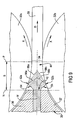
- Lines in those sections showing alloy at the solidus temperature also have a V-shape form, pointing in that direction and extending from those contact points, but with the arms of the V-shape having a larger included angle.
- the temperature gap between those lines for alloy at the liquidus and the solidus increases in the direction of travel with distance from each roll surface to the centre of the forming strip. It is required that the increase in this gap be kept to a minimum. In general, it is found that this is achieved if the strip exhibiting from the bite of the rolls has a surface temperature below about 400°C, such as within the range of from 300°C to 400°C.
- the set-back which also varies with the diameter of the rolls, may be in the range of about 12mm to about 17mm for rolls having a diameter of about 185mm.
- the set-back increases or decreases with increase or decrease in the diameter of the rolls and, for example, for rolls having a diameter of about 255mm, the set-back most preferably is from about 28 to about 33mm, such as about 30mm.
- the initial part of the set-back is dependent upon the diameter of the rolls and the set-back.
- the initial part of the set-back most preferably is such that factors including the surface tension of the magnesium alloy and the melt head are able to maintain a convex meniscus at each of the upper and lower molten metal surface over the length of that initial part.
- that initial part may be up to 35%, such as from about 10% to 30% of the set-back, with solidification of alloy to be achieved in the remainder of that length and in advance of the bite of the rolls.
- full solidification of the alloy between upper and lower surfaces preferably proceeds in advance of the final 5% to 15% of the set-back which immediately precedes the bite of the rolls.
- full solidification of the alloy throughout the thickness of strip being formed may need to be achieved in not more than about 50% of the set-back distance.
- some cooling from the superheat temperature will occur in the nozzle and in the initial part of the set-back.
- the features of the present invention for twin roll casting of magnesium alloys enable a practical benefit relative to standard practices in relation to aluminium alloys. This is in relation to start-up for commencement of a casting cycle.
- the procedures enabled by the present invention enable start-up in not more than a few minutes, such as from 0.5 up to 3 to 5 minutes for the invention compared with up to 50 minutes for standard practices for aluminium alloys.
- roll speed initially is substantially lower, such as by 40%, than production speed.
- the lower speed enables filling of the chamber defined by the nozzle and the rolls, and quick commencement of production of "hard sheet" of full thickness and width.
- the roll speed is increased to attain stable operation at production roll speed.
- equilibrium operating temperatures are able to be attained efficiently, in a short period of time, by preheating the tundish, or other feed device, and the nozzle.
- hot air preferably is blown into and through the tundish, and then through the nozzle so as to exit from the nozzle outlet.
- the hot air is at a temperature sufficient to heat the tundish quickly to close to its required operating temperature, and may be from about 500°C to 655°C, such as from 550°C to 600°C.
- the nozzle is heated to a sufficient temperature ranging down to about 200°C to 400°C along the nozzle outlet.
- the nozzle has internal guide members for directing alloy to each end of the outlet, to achieve uniform alloy flow along the length of the outlet
- the nozzle temperature may be about 400°C at each end of the outlet and, due to hot air being impeded by the guide members, about 200°C at a central region of the outlet.
- the preheating used in the process of the present invention enables equilibrium operating temperatures to be established in not more than a few minutes, such as about 3 to 5 minutes.
- the lay-off procedure gives rise to a substantial risk of molten alloy not being solidified before passing through the bite of the rolls such that, with magnesium alloys, there is a substantial fire risk.
- the hard-sheet procedure more readily ensures that all alloy is solidified before passing through the rolls, there is a fire-risk arising from there being an increased possibility of molten alloy flooding from the chamber, between the nozzle and the rolls.
- the present invention obviates the need for either of these protracted start-up procedures used for twin roll casting of aluminium alloys, since the short time required for temperature equilibrium to be obtained enables start-up with close to full operational roll speed. Thus, the output of full thickness, full width sheet or strip is able to be quickly established.
- twin roll casting in accordance with the present invention, it is found that there can be considerable temperature variation across the width of strip or sheet exiting from the bite or gap of the rolls.
- the variation is such that a central region of the strip is hotter than edge regions.
- the variation in temperature can be up to about 70°C, and generally is in excess of about 20°C.
- the temperature variation can introduce a surface defect referred to as hot-line, and/or can result in the strip twisting due to thermal stress. Similar temperature variation and consequences can be encountered in alloys other than magnesium alloys.
- the modified nozzle has a top plate and a bottom plate, with the lateral extent of the outlet of the nozzle being defined by a respective edge of each of the plates. Over a central region of at least one of the plates, that edge is set back relative to end regions of the edge. The central region of the edge has a length and location corresponding to the central region of strip or sheet to be cast. While a central region of each plate may be set back, it is preferred that only the top plate has such set back central region.
- the set-back preferably is substantially uniform across the central region, although the set-back may be of concave arcuate form.
- the set-back preferably is less than about 7mm, such as from 2 to 4mm.
- the present invention does not obviate the need for use of the established procedures based on the use of a suitable flux and atmosphere. However it does enable this risk to be still further reduced.
- the efficient start-up procedures enabled by the present invention substantially avoids the risk of fire from molten alloy not being solidified full before passing through the rolls or from molten alloy flooding from the chamber between the nozzle and the rolls.
- the low roll load of about 2 to 500 kg/mm and corresponding low level of rolling reduction combined with limited superheating and rapid solidification in advance of the bite between the rolls, further reduce the risk of molten alloy passing through the bite and being exposed to the atmosphere by cracking or surface defects.
- the invention does not obviate the need for use of a suitable atmosphere to control fire risk.
- an important preferred form of the invention provides an improvement on established procedures.
- a mixture of sulphur hexafluoride in dry air is not suitable for magnesium alloys high in aluminium, while it is not always reliable at start-up or at the end of a casting run.
- we have found that substantial improvement is possible by adding to the mixture a few percent, such as from about 2 to 6 volume %, of a hydrofluorocarbon.
- the compound 1,1,1,2-tetrafluoroethane referred to by the designation HFC-134a, is particularly preferred.
- other gases can be used with or without SF 6 /HFC-134a.
- a protective atmosphere of SF 6 /dry air or other suitable atmosphere is maintained to protect against the risk of a fire.
- the mixture as supplied also contains the hydrofluorocarbon, preferably HFC-134a. This significantly improves the protection against fire risk.
- the hydrofluorocarbon preferably HFC-134a.
- the strip can have a microstructure having the secondary dendritic arm spacing of primary magnesium refined to about 5 to 15 ⁇ m, compared with 25 to 100 ⁇ m for magnesium alloy microstructures resulting from conventional casting technologies. This refinement leads to uniform distribution of intermetallic secondary phases, thereby facilitating improvement in mechanical properties by cold working of the strip.
- the rapid solidification refines the size of particles of intermetallic secondary phases to about 1 ⁇ m, compared to up to 25 to 50 ⁇ m for magnesium alloy microstructures from conventional casting technologies. This refinement minimises crack initiation around those particles, further facilitating improvement in mechanical properties by cold working of the strip.
- the rapid solidification can be controlled for achieving equi-axed growth of alpha magnesium dendrites across the thickness of strip being formed, by variation in the cooling rate from initial to final solidification through to the middle of the strip thickness.
- melt treatment such as grain refining, minimizes detrimental centre-line segregation, while maintaining the integrity of the as-cast magnesium alloy strip.
- This is not an issue in the twin roll casting of aluminium alloys as the alpha aluminium dendrites are always columnar-like, as there is no segregation problems for these alloys.
- the magnesium alloy strip produced by the present invention is well suited to processing for controlling its microstructure and properties.
- hot rolling and final heat treatment can be carried out on the as-cast strip to refine the microstructure and enhance the mechanical properties of resultant final gauges.
- Typical requirements for a range of applications necessitate the refinement of primary magnesium grain size and substantially uniform properties in both longitudinal and transverse directions.
- one or two longitudinal cold rolling passes, followed by suitable heat treatment can refine the primary magnesium grains by recrystallization.
- applying controlled transverse strain and suitable heat treatment, both after one or two longitudinal cold rolling passes enables refinement of primary magnesium grains, as well as substantially uniform transverse and longitudinal mechanical properties.
- the installation 10 has a furnace 12 for maintaining a supply of molten magnesium alloy, and a tundish enclosure 14.
- the alloy is able to flow as required from furnace 12 to tundish enclosure 14 via transfer supply tube 16 under an arrangement operable to maintain a substantially constant head of alloy in enclosure 14.
- Overflow alloy is able to flow from enclosure 14 via tube 18, for collection in container 20.
- enclosure 14, container 20 and tube 16 there is a respective inlet connector 22 by which a gas, for maintaining a protective atmosphere as detailed earlier herein, is able to be supplied from a suitable source (not shown).
- Each of furnace 12 and container 20 has an outlet connector 24 by which the gas is able to discharge for flow to a recovery vessel (not shown).
- Tundish 26 for enclosure 14 is shown in Figures 2 and 3.
- Tundish 26 has front and rear walls 26a and 26b, side walls 26c and a base 26d which together define a chamber 28.
- Tundish 26 also has a cover (not shown) and a transverse baffle 30 which extends between walls 26c but has its lower edge spaced from base 26d. Baffle 30 thus divides chamber 28 into a rear portion 28a and a forward portion 28b.
- Installation 10 also includes a nozzle 30 and a roll arrangement 32.
- Nozzle 30 extends forwardly from wall 26a of tundish 26, and into a gap between upper and lower rolls 32a and 32b of arrangement 32.
- the rolls 32a, 32b extend horizontally and are vertically spaced to define a bite or nip 34 therebetween.
- Arrangement 32 also includes an exit table or conveyor 35 on the side of rolls 32a,32b remote from nozzle 30.
- Figures 2 and 3 and that of Figures 4 and 5 show alternative forms of nozzle 30. Corresponding parts of these have the same reference numeral.
- the nozzle 30 has horizontally disposed, vertically spaced upper and lower plates 36 and 37 and opposite side plates 38.
- An alloy flow cavity 39 extends through nozzle 30 and is defined by horizontal plates 36,37 and side plates 38. Alloy in tundish 26 is able to flow into nozzle 30 through an opening 40 in the front wall 26a of tundish 26, with alloy able to discharge between rolls 32a,32b from an elongate outlet 42 along the edge of plates 36,37 remote from tundish 26.
- plates 36,37 and side plate 38 are tapered so as to be able to extend close to each of rolls 32a,32b.
- outlet 42 is set back from a plane P containing the axes of rolls 32a,32b such that a chamber 44 is defined between nozzle 30 and rolls 32a,32b.
- tundish 26 and nozzle 30 initially are pre-heated to temperature levels detailed earlier herein.
- a hot air gun 46 (shown in Figures 2 and 3) is able to be inserted into an opening 48 in rear wall 26b of tundish 26.
- gun 46 is retracted and opening 48 is closed.
- Molten alloy then is caused to flow from furnace 12, along tube 16 and into tundish 26.
- Alloy in tundish 26 is maintained at a required level, shown by broken line L in Figures 1 and 2, above a horizontal plane represented by line M through the centre of nozzle outlet 42 and the bite or nip 34 of rolls 32a,32b.
- the molten alloy is protected by maintaining a suitable atmosphere as detailed earlier herein, with the gas for providing this being supplied to connectors 22.
- the atmosphere is maintained at a pressure slightly above atmospheric pressure, with over-flow gas being collected from connectors 24.
- the alloy flows at a controlled rate through opening 40 to cavity 39 of nozzle 30. From cavity 39, the alloy discharges through the length of outlet 42, into chamber 44, and then through the bite or nip 34 between rolls 32a,32b.
- the rolls 32a,32b are internally water-cooled and rotated in unison in the respective directions shown by arrows X.
- the molten alloy progressively solidifies in chamber 44 due to the cooling effect of rolls 32a,32b, to form magnesium alloy strip 50 (as shown in Figure 9) which passes along table 35.
- table 35 may have openings 35a adjacent to its edge nearer to rolls 32a,32b, through which pressurised gas is able to be supplied against the lower surface of the strip 50, to further cool the strip and assist its movement onto table 35.
- FIGs 6 and 7 show alternative arrangements in which plates 36,37 of nozzle 30 are provided by two similar modules 30a and 30b.
- Each module is able to receive molten alloy from a respective tundish 26, with each tundish receiving alloy from a furnace 12 via a common tube 16 ( Figure 6) or a respective tube 16 ( Figure 7).
- Figure 8 is similar to Figure 6. However, rather than one pair of modules receiving alloy via a common tube 16, there are two pairs of modules, with each pair having a respective tube 16 common to its modules.
- the set-back, the melt head, the speed of rotation of rolls 32a and 32b and the load applied by rolls 32a,32b to the alloy are controlled to achieve a required alloy flow rate for a given roll diameter.
- the point of convergence of lines 58a,58b on about plane M represents substantially full solidification and, as detailed earlier herein, this is to be attained in advance of the alloy reaching bite or nip 34 (i.e. plane P).
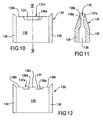
- Figures 10 and 11 show a nozzle 130 having a top plate 136, a bottom plate 137 and side plates 138. At their forward edges, plates define an elongate nozzle outlet 142.
- the lower plate 137 has a forward edge 137a which extends linearly between plates 138.
- top plate 136 would have a corresponding edge, but strip cast with such normal arrangement would have a central region which is hotter than edge regions.
- top plate 136 has an edge which has a central region 136a which is recessed rearwardly from respective edge regions 136b thereof. This arrangement, as detailed earlier herein, enables temperature variation across the width of cast strip to be reduced, with adverse consequences of the variation reduced or avoided.
- top plate 136 is set back at two central regions 136a between edge regions 136b, with there being a mid-region 136c between the two regions 136a.
- This arrangement is suitable where more complex temperature variation results from internal spacers between plates 136,137.
Landscapes
- Engineering & Computer Science (AREA)
- Mechanical Engineering (AREA)
- Continuous Casting (AREA)
- Manufacture Of Alloys Or Alloy Compounds (AREA)
- Mold Materials And Core Materials (AREA)
- Powder Metallurgy (AREA)
Abstract
Description
- This invention relates to twin roll casting of magnesium and magnesium alloys (herein generally referred to collectively as "magnesium alloy").
- The concept of twin roll casting of metals is old, dating back at least to inventions by Henry Bessemer in the mid-1900's. However, it was not until about 100 years later that interest in possible commercial use of twin roll casting began to be investigated. The concept as proposed by Bessemer was based on the production of strip using a metal-feeding system in which molten metal was fed upwardly through a bite defined between two laterally spaced, parallel rolls. More recent proposals were based on a downwards feed of molten metal to the rolls. However it has become accepted that the preferred arrangement is with the rolls spaced vertically, rather than horizontally as in those earlier proposals, with the alloy feed being substantially horizontal. While the rolls are spaced vertically, their axes preferably are in a plane which is inclined at a small angle of up to about 15° to the vertical. With this inclination, the lower roller is displaced downstream, relative to the upper roller, with respect to the direction of alloy feed to and beyond the bite.
- While there has been some commercial use of twin roll casting, this has been limited in its extent. It also has been limited in the range of alloys to which it is applied, since use essentially has been restricted to suitable aluminium alloys. To this stage, there has been limited success in establishing a suitable process for twin roll casting of magnesium alloys.
- In achieving a practical process for successfully twin roll casting of magnesium alloys, such as on a substantially continuous or a semi-continuous basis, there are several problems which need to be overcome. A first of these is that magnesium alloy melts tend to oxidise and catch fire, while moisture from any source presents a potential risk of explosion. There are established procedures based on use of a suitable flux or a suitable atmosphere to prevent oxidation and risk of fire, while moisture is able to be excluded. Also, magnesium and some magnesium alloys that do not contain or have only low additions of beryllium, such as AZ31, can have a high tendency to oxidise in the melt state, such that conventional flux or the atmosphere control is not adequate during the twin roll casting operation. However, overcoming these problems adds to the complexity of processes for twin roll casting such that the complexity is a problem.
- A further problem is that magnesium alloys have a thermal capacity such that, relative to aluminium alloys, they tend to freeze quickly. Also, again relative to aluminium alloys, some magnesium alloys such as AM60 and AZ91 have a considerably larger freezing range, or temperature gap between the solidus and liquidus temperatures. The range or gap may be about 70 to 100°C or higher for magnesium alloys, compared with about 10 to 20°C for many aluminium alloys. The large freezing range or gap gives rise to surface defects and internal segregation defects in twin roll cast sheet in the as-cast condition.
- Importantly, there is the problem of the continuous requirement to reduce operating costs, including costs for consumables and casting preparation and thereby make twin roll casting more competitive with alternative technology, more flexible for both short operating periods (e.g. one day) and long operating periods (e.g. weeks), and enable its range of application to be extended. This is a general problem for twin roll casting technology, but is more severe for the casting of magnesium alloys in view of other problems discussed above. Also, there is a problem in extending twin roll casting technology in order to enhance the physical properties of strip material produced. While this also is a general problem for the technology, it is particularly acute in the case of magnesium alloys due to problems in producing substantially crack-free strip which has good surface quality and is substantially free of internal segregation defects.
- The present invention is directed to providing a process for the twin roll casting of magnesium and magnesium alloys which, at least in preferred forms, enables one or more of the above problems to be ameliorated.
- The present invention is directed to providing an improved process for twin roll casting of magnesium alloys, to produce magnesium alloy strip of a required thickness and width. The process of the invention enables the width of the strip to be up to and beyond about 300mm, such as up to about 1800mm, as required. In general, the thickness of the strip can range from about 1 mm or less, up to about 15mm, but preferably the thickness is from about 3mm to about 8mm.
- The process of the present invention provides for the casting of magnesium alloy by supplying molten alloy to a chamber formed between a nozzle and a pair of oppositely rotating, substantially parallel rolls which are internally fluid cooled and which are spaced generally one above the other to define a bite there between. The process includes introducing molten magnesium alloy through the nozzle, and cooling the magnesium alloy by heat energy extraction therefrom by the cooled rolls whereby substantially complete solidification of the magnesium alloy is achieved in the chamber, prior to the magnesium alloy passing through the bite defined between the rolls.
- These general features of the process of the present invention are the same as those required for twin roll casting of aluminium alloys. However, this essentially is the extent of similarity between respective processes for magnesium alloys and for aluminium alloys. Indeed despite the indicated similarity, the process for casting of aluminium alloys provides little if any guidance as to a process suitable for magnesium alloys. Also, to the extent that twin roll casting has been attempted with other alloys, these are found to necessitate processes which are similar to that required for aluminium alloys and which also provide little if any guidance as to a process suitable for magnesium alloys.
- Thus, according to the invention, there is provides a process for the production of magnesium alloy strip, by twin roll casting, wherein the process includes the steps of:
- (a) passing molten alloy from a source of supply to a feeding device;
- (b) feeding molten alloy from the feeding device through a nozzle to a chamber formed between an elongate outlet of the nozzle and a pair of substantially parallel rolls which are spaced one above the other to define a bite therebetween;
- (c) rotating said rolls in opposite directions whereby alloy is drawn from the chamber through the bite simultaneously with the feeding of step (b); and
- (d) flowing coolant fluid through each roll during the rotating step (c) to provide internal cooling of the rolls and thereby cooling alloy received in the chamber by heat energy extraction by the cooled rolls whereby substantially complete solidification of the magnesium alloy is achieved in the chamber prior to alloy passing through the bite defined between rolls and issuing therefrom as hot rolled alloy strip;
- maintaining alloy held at the source at a temperature sufficient to maintain alloy in the feed device at a superheated temperature above its liquidus temperature for the alloy;
- In the process of the invention, the magnesium alloy may be supplied to an inlet end of the nozzle, for flow therethrough to enter the chamber through an outlet end of the nozzle, from a feed device comprising a tundish to which the alloy is supplied from a suitable source of molten alloy. However, a float box or other alternative form of feed device can be used in place of a tundish. It is required that the feed device provides a controlled, substantially constant melt head for the molten magnesium alloy. That is, molten alloy in the tundish, float box or the like is required to be maintained at a depth such that the surface of the molten alloy therein is at a controlled, substantially constant height (or melt head) above the intersection between a horizontally extending central plane of the nozzle and a plane containing the axes of the rolls. Relative to that intersection, which substantially corresponds to the centre line of the bite of the rolls in that plane, the melt head for casting magnesium alloy of the above-indicated strip thickness provided by the invention, preferably is from 5mm to 22mm. The melt head may be from 5mm to 10mm for magnesium and magnesium alloys with lower levels of alloy element addition, such as commercial pure magnesium and AZ31, and from 7mm to 22mm for magnesium alloys with higher levels of alloy element addition, such as AM60 and AZ91.
- The melt head of 5 to 22mm required by the present invention is in marked contrast to requirements for twin roll casting of aluminium alloys. In the latter case, the melt head generally is kept to a minimum of about 0 to 1 mm. This difference, significant in itself, is inter-related with a number of other important differences, as will become apparent from the following description.
- In the process of the invention, the magnesium alloy supplied to the tundish or other feed device is superheated above its liquidus temperature. The extent of superheating may be to a temperature of from about 15°C to about 60°C above the liquidus temperature. In general, the lower end of this range, such as from 15°C to about 35°C, preferably from about 20°C to 25°C, is more appropriate for magnesium and alloys with lower levels of alloy element additions. For alloys with higher levels of alloy element additions, the upper end of the range, from about 35°C to about 50°C to 60°C, generally is more appropriate.
- The extent of superheating necessary in twin roll casting of magnesium alloys is similar to that required for aluminium alloys. With twin roll casting of aluminium alloys, superheating is to a level of about 20°C to 60°C, usually about 40°C, above the alloy liquidus, compared to the 15°C to 35°C for magnesium alloys with lower levels of additions or 35°C up to 50°C to 60°C for magnesium alloys with higher levels of additions required for the invention. Despite this similarity, there are important fundamental dissimilarities between the two distinct aluminium and magnesium alloy types. An important dissimilarity between the aluminium alloys and magnesium alloys, particularly magnesium alloys with higher levels of alloy element addition, is indicated by the respective temperature gap between liquidus and solidus temperatures. Thus, whereas aluminium alloys usually have a liquidus/solidus temperature gap of about 10°C to 20°C, that gap for at least magnesium alloys with higher levels of alloy element addition is more usually from about 70°C to 100°C, but can be substantially in excess of that range. Even where the freezing ranges for aluminium alloys and the magnesium alloys are similar, such as with magnesium alloys with lower levels of alloy element addition, the magnesium alloys have much better castability than aluminium alloys.
- In the twin roll casting of magnesium alloys with higher levels of alloy element addition, full solidification of the molten alloy must be controlled to be within a relatively narrow region between the outlet of the nozzle and the bite of the rolls. In view of this, it is surprising that significant superheating above the alloy liquidus is appropriate. It will be appreciated that such superheating significantly increases the quantity of heat energy which needs to be extracted from the molten alloy in order to achieve full solidification of the alloy. As also will be appreciated, the relatively wide liquidus/solidus temperature gap of magnesium alloys, such as with higher levels of alloy element addition, also makes full solidification control difficult to attain. However, in general, the required control is able to be achieved where the casting is conducted under conditions providing for alloy strip exiting from the rolls to have a surface temperature within a required range. In particular, it is necessary that alloy strip exits from the rolls with a surface temperature below about 400°C.
- With twin roll casting of magnesium alloys, full solidification of the molten alloy again must be controlled to be within a relatively narrow region between the outlet of the nozzle and the bite of the rolls. The zone is not as narrow for alloys with lower levels of alloy element addition as it is for alloy with a high level of alloy element addition. Despite this and the lower level of superheating appropriate for alloys with the low levels of alloy element addition, the level of superheating these alloys again is surprising, even if more acceptable, given the narrower freezing range applicable. Again, the required control is able to be achieved where the casting is conducted under conditions providing for strip exiting from the rolls to have a surface temperature below about 400°C. However, the temperature preferably is substantially below 400°C, such as from about 180°C to about 300°C, for alloys with low levels of alloy element addition.
- As indicated above, a strip surface temperature of below about 400°C is necessary. However, the extent to which it is desirable for the temperature to be below that level varies with the level of alloy element addition. For magnesium alloys with higher levels of alloy element addition, a surface temperature of from about 300°C to 400°C alloy strip exiting from the rolls is necessary to enable the production of crack-free strip with good surface finish. For alloy with a lower level of alloy element addition, a lower surface temperature ranging from 300°C down to about 180° is necessary for production of crack-free strip of good surface finish.
- At progressively higher temperatures, the likelihood of cracks, surface defects and ultimately hot spots, increases. However, attaining such temperatures in strip exiting from the rolls necessitates a very high level of heat energy extraction, particularly with alloy having lower levels of alloy element addition. As will be appreciated, the heat energy extraction needs to be such as to allow for the heat energy due to superheating, the level of heat energy necessary to bridge the temperature gap between the liquid and solidus for the alloy, and the need to reach a surface temperature substantially below the solidus temperature. However, the surface temperature to be attained in the overall range of 180°C to 400°C depends on the solidus temperature for a given alloy. It also can decrease with increasing strip thickness since the surface temperature is to be such as to give rise to a suitable temperature below the solidus at the centre of the strip.
- The indicated upper limit of 400°C for strip surface temperature is at a level which is from about 40°C to 190°C below the solidus temperatures for magnesium casting alloys. To ensure that the temperature at the centre of the strip is at a suitable level, the surface temperature preferably is not less than about 85°C below the solidus temperature for a given alloy. The need for this is not simply to ensure that the strip has solidified throughout. Rather, it is to ensure that throughout its thickness the alloy strip has sufficient strength to enable its production without cracking or surface defects, under the specific load necessarily applied to the rolls.
- The need to attain a surface temperature in the indicated range below 400°C, in the production of magnesium alloy strip is a feature distinguishing the process of the invention from a process for producing aluminium alloy strip. With the aluminium alloys, it is necessary only that the strip has solidified throughout its thickness, such that the centre of the strip is able to be just below the solidus temperature. Under such conditions, the aluminium alloy strip has sufficient strength to enable it to be hot rolled. However, with magnesium alloy strip, it is necessary that substantially the full thickness is sufficiently below the solidus temperature in order that the strip can be subjected to hot rolling.
- The level of the specific load is a further feature by which the present invention differs significantly from a process for production of strip of aluminium alloy. The specific load applied to the rolls in the process of the present invention for magnesium alloys is from about 2 kg to about 500 kg per mm of roll length. The range preferably is from 100 to 500 kg/mm. However, the range can be as low as about 2 to about 20 kg/mm and hence the specific load in the process of the present invention can be more than an order of magnitude lower than the specific loads used in producing aluminium alloy strip by twin roll casting. For aluminium alloys, a specific load of from about 300 to about 1200 kg/mm is usual. In each case, there is resultant hot rolling of the alloy moving to and passing through the bite of the rolls. The level of specific load used for aluminium alloys results in hot rolling giving rise to a thickness reduction of from about 20% to about 25%. In contrast, the specific load required for the present invention results in a thickness reduction of from about 4% to about 9% in magnesium alloy strip being produced.
- As with the alloy strip surface temperature range of 180°C to 400°C, the level of applied load and resultant thickness reduction are to facilitate production of magnesium alloy strip which is substantially free of cracks and has good surface quality. At higher levels of applied load and thickness reduction, production of strip which is substantially free of cracks is more difficult to achieve, while surface defects also become more likely to arise.
- To allow for the liquidus/solidus gap and also to avoid segregation, it is necessary that heat energy extraction from the molten and solidifying magnesium alloy of proceeds relatively rapidly. Alloy contacting the surface of each roll drops rapidly in temperature to below the solidus but, as solidification proceeds through to the centre of strip being formed, cooling is less rapid. As the strip being formed is advancing towards the bite between the rolls, lines in longitudinal sections through the thickness of the strip showing alloy at the liquidus temperature have V-shape form, pointing in the direction of strip advance and extending from points at which the alloy contacts each roll. Lines in those sections showing alloy at the solidus temperature also have a V-shape form, pointing in that direction and extending from those contact points, but with the arms of the V-shape having a larger included angle. Thus, the temperature gap between those lines for alloy at the liquidus and the solidus, increases in the direction of travel with distance from each roll surface to the centre of the forming strip. It is required that the increase in this gap be kept to a minimum. In general, it is found that this is achieved if the strip exhibiting from the bite of the rolls has a surface temperature below about 400°C, such as within the range of from 300°C to 400°C.
- In the chamber formed between nozzle and the rolls, cross-sections parallel to a plane through the axes of the rolls decrease in area, through to a minimum at the bite between the rolls, due to the curved surfaces of the rolls. The distance from the nozzle outlet to that plane is referred to as the "set-back". In its flow over the distance of the set-back, molten magnesium alloy issuing from the outlet travels a short initial part of the set-back distance before making contact with the rolls. The contact with each roll is along a longitudinal line on its surface. The distance from the outlet to the respective contact line of each roll is dependent upon the width of lips of the nozzle defining the outlet, the closeness of fitting of the nozzle between the rolls and the diameter of the rolls. In the process of the invention the set-back, which also varies with the diameter of the rolls, may be in the range of about 12mm to about 17mm for rolls having a diameter of about 185mm. The set-back increases or decreases with increase or decrease in the diameter of the rolls and, for example, for rolls having a diameter of about 255mm, the set-back most preferably is from about 28 to about 33mm, such as about 30mm.
- The initial part of the set-back, from the outlet of the nozzle to the above-mentioned line at which the alloy makes contact with the surface of each roll, is dependent upon the diameter of the rolls and the set-back. However, the initial part of the set-back most preferably is such that factors including the surface tension of the magnesium alloy and the melt head are able to maintain a convex meniscus at each of the upper and lower molten metal surface over the length of that initial part. Depending on the thickness of strip to be produced, that initial part may be up to 35%, such as from about 10% to 30% of the set-back, with solidification of alloy to be achieved in the remainder of that length and in advance of the bite of the rolls. From the lines of contact the convex meniscus of alloy makes with the rolls, full solidification of the alloy between upper and lower surfaces preferably proceeds in advance of the final 5% to 15% of the set-back which immediately precedes the bite of the rolls. Thus, full solidification of the alloy throughout the thickness of strip being formed may need to be achieved in not more than about 50% of the set-back distance. However, some cooling from the superheat temperature will occur in the nozzle and in the initial part of the set-back.
- The features of the present invention for twin roll casting of magnesium alloys enable a practical benefit relative to standard practices in relation to aluminium alloys. This is in relation to start-up for commencement of a casting cycle. The procedures enabled by the present invention enable start-up in not more than a few minutes, such as from 0.5 up to 3 to 5 minutes for the invention compared with up to 50 minutes for standard practices for aluminium alloys.
- In the standard practices for twin roll casting of aluminium alloys, there is used either a lay-off or a hard-sheet start-up. In a lay-off start-up, the rolls are rotated substantially in excess of production speed, such as by 40%, when a casting cycle commences. The molten alloy is unable to fill the chamber defined between the nozzle and the rolls at the higher roll speed. Thus, only broken sheet, which is thinner and narrower than required is produced, although the width progressively increases. When full width is achieved, the roll speed is gradually reduced, enabling the thickness of the sheet to increase progressively. Eventually, the chamber is full and stable operation at production roll speed is established.
- For the hard-sheet start-up, roll speed initially is substantially lower, such as by 40%, than production speed. The lower speed enables filling of the chamber defined by the nozzle and the rolls, and quick commencement of production of "hard sheet" of full thickness and width. Gradually the roll speed is increased to attain stable operation at production roll speed.
- The substantial period of time necessary to attain production roll speed with each of these forms of standard practice for twin roll casting of aluminium alloys obviates the need for effective and efficient temperature stabilization. Thus, production start-up is by superheated molten alloy being supplied to a tundish, for flow from the latter to the nozzle. Heating of the tundish and nozzle by incoming alloy is gradual and it necessarily takes a substantial period to attain equilibrium operating temperatures throughout the casting apparatus.
- In the present invention, it is found that equilibrium operating temperatures are able to be attained efficiently, in a short period of time, by preheating the tundish, or other feed device, and the nozzle. For this, hot air preferably is blown into and through the tundish, and then through the nozzle so as to exit from the nozzle outlet. The hot air is at a temperature sufficient to heat the tundish quickly to close to its required operating temperature, and may be from about 500°C to 655°C, such as from 550°C to 600°C. In the short time for this to be achieved, the nozzle is heated to a sufficient temperature ranging down to about 200°C to 400°C along the nozzle outlet. Where, for example, the nozzle has internal guide members for directing alloy to each end of the outlet, to achieve uniform alloy flow along the length of the outlet, the nozzle temperature may be about 400°C at each end of the outlet and, due to hot air being impeded by the guide members, about 200°C at a central region of the outlet.
- The preheating used in the process of the present invention enables equilibrium operating temperatures to be established in not more than a few minutes, such as about 3 to 5 minutes. Thus, the lay-off procedure gives rise to a substantial risk of molten alloy not being solidified before passing through the bite of the rolls such that, with magnesium alloys, there is a substantial fire risk. Also, while the hard-sheet procedure more readily ensures that all alloy is solidified before passing through the rolls, there is a fire-risk arising from there being an increased possibility of molten alloy flooding from the chamber, between the nozzle and the rolls. The present invention obviates the need for either of these protracted start-up procedures used for twin roll casting of aluminium alloys, since the short time required for temperature equilibrium to be obtained enables start-up with close to full operational roll speed. Thus, the output of full thickness, full width sheet or strip is able to be quickly established.
- In the course of twin roll casting, in accordance with the present invention, it is found that there can be considerable temperature variation across the width of strip or sheet exiting from the bite or gap of the rolls. The variation is such that a central region of the strip is hotter than edge regions. The variation in temperature can be up to about 70°C, and generally is in excess of about 20°C. The temperature variation can introduce a surface defect referred to as hot-line, and/or can result in the strip twisting due to thermal stress. Similar temperature variation and consequences can be encountered in alloys other than magnesium alloys.
- We have found that the temperature variation can at least be reduced by use of a modified form of nozzle. The modified nozzle has a top plate and a bottom plate, with the lateral extent of the outlet of the nozzle being defined by a respective edge of each of the plates. Over a central region of at least one of the plates, that edge is set back relative to end regions of the edge. The central region of the edge has a length and location corresponding to the central region of strip or sheet to be cast. While a central region of each plate may be set back, it is preferred that only the top plate has such set back central region.
- The set-back preferably is substantially uniform across the central region, although the set-back may be of concave arcuate form. The set-back preferably is less than about 7mm, such as from 2 to 4mm. With such set-back aligned with a region of the strip at which a relatively higher temperature would prevail but for the set-back, the temperature difference across the width of the strip is able to be substantially reduced or eliminated. Thus, hotline is reduced or prevented, while twisting of the strip is reduced or prevented.
- It is indicated above that, with the twin roll casting of magnesium alloys, there are several problems which need to be overcome. The first of these is the risk of oxidation and fire. The present invention does not obviate the need for use of the established procedures based on the use of a suitable flux and atmosphere. However it does enable this risk to be still further reduced. Thus, the efficient start-up procedures enabled by the present invention substantially avoids the risk of fire from molten alloy not being solidified full before passing through the rolls or from molten alloy flooding from the chamber between the nozzle and the rolls. Also, the low roll load of about 2 to 500 kg/mm and corresponding low level of rolling reduction, combined with limited superheating and rapid solidification in advance of the bite between the rolls, further reduce the risk of molten alloy passing through the bite and being exposed to the atmosphere by cracking or surface defects.
- As indicated, the invention does not obviate the need for use of a suitable atmosphere to control fire risk. However, an important preferred form of the invention provides an improvement on established procedures. In relation to fire risk control, it is common practice to use a mixture of sulphur hexafluoride in dry air. The SF6/dry air mix is not suitable for magnesium alloys high in aluminium, while it is not always reliable at start-up or at the end of a casting run. In each case, we have found that substantial improvement is possible by adding to the mixture a few percent, such as from about 2 to 6 volume %, of a hydrofluorocarbon. The compound 1,1,1,2-tetrafluoroethane, referred to by the designation HFC-134a, is particularly preferred. However, other gases can be used with or without SF6/HFC-134a.
- During a casting operation, a protective atmosphere of SF6/dry air or other suitable atmosphere is maintained to protect against the risk of a fire. Where the alloy being cast is one for which that mixture provides limited protection, the mixture as supplied also contains the hydrofluorocarbon, preferably HFC-134a. This significantly improves the protection against fire risk. However, for alloys for which the SF6/dry air mixture generally is effective, it generally is necessary to add the hydrofluorocarbon for a short period at start up and at termination of a casting operation.
- The problem of premature freezing is substantially overcome by the rapid establishment of equilibrium operating temperatures and high speed, assisted by the good castability of magnesium alloys. Significant factors enabling this are preheating such as described above, and quick attainment of roll speed and, hence, other operating conditions.
- Difficulties arising from wide freezing range of magnesium alloys with high levels of additions are addressed by features of the present invention which also facilitate the enhancement of the physical properties of magnesium alloy strip produced by the invention. There is a number of inter-related features which are relevant to these matters.
- With aluminium alloys, rapid solidification is able to be achieved by the good contact quality between the molten alloy and the surface of the rolls due to the large rolling reduction of about 20% to 25%. However, with magnesium alloys, such level of rolling reduction is not suitable as it will introduce surface defects, such as surface cracking. However, achieving a convex meniscus maintains an optimised contact of molten magnesium alloy with each roll, and establishes a uniform solidification front enabling sufficiently rapid solidification. The convex menisci are achieved by the substantial melt head required by the present invention, while the contact between the alloy and the rolls still is enhanced by the lower level of rolling reduction necessary to avoid surface defects, such as cracks. With aluminium alloys, the high level of rolling reduction and small, if any, melt head substantially preclude convex menisci, and produce menisci which are concave or vary between concave and convex.
- With the rapid solidification enabled by the present invention for the production of magnesium alloy strip, it is found that a number of practical benefits are able to be achieved. Thus, the strip can have a microstructure having the secondary dendritic arm spacing of primary magnesium refined to about 5 to 15 µm, compared with 25 to 100 µm for magnesium alloy microstructures resulting from conventional casting technologies. This refinement leads to uniform distribution of intermetallic secondary phases, thereby facilitating improvement in mechanical properties by cold working of the strip.
- Also, the rapid solidification refines the size of particles of intermetallic secondary phases to about 1 µm, compared to up to 25 to 50 µm for magnesium alloy microstructures from conventional casting technologies. This refinement minimises crack initiation around those particles, further facilitating improvement in mechanical properties by cold working of the strip.
- Moreover, the rapid solidification can be controlled for achieving equi-axed growth of alpha magnesium dendrites across the thickness of strip being formed, by variation in the cooling rate from initial to final solidification through to the middle of the strip thickness. This, together with melt treatment such as grain refining, minimizes detrimental centre-line segregation, while maintaining the integrity of the as-cast magnesium alloy strip. This is not an issue in the twin roll casting of aluminium alloys as the alpha aluminium dendrites are always columnar-like, as there is no segregation problems for these alloys.
- Additionally, the magnesium alloy strip produced by the present invention is well suited to processing for controlling its microstructure and properties. Thus, hot rolling and final heat treatment can be carried out on the as-cast strip to refine the microstructure and enhance the mechanical properties of resultant final gauges. Typical requirements for a range of applications necessitate the refinement of primary magnesium grain size and substantially uniform properties in both longitudinal and transverse directions. We have established that one or two longitudinal cold rolling passes, followed by suitable heat treatment, can refine the primary magnesium grains by recrystallization. Also, applying controlled transverse strain and suitable heat treatment, both after one or two longitudinal cold rolling passes, enables refinement of primary magnesium grains, as well as substantially uniform transverse and longitudinal mechanical properties.
- As to operating costs, it will be appreciated that the ability to achieve stable solidification and establishment of production within a few minutes is particularly significant. Establishing stable thermal distributions is of importance in this regard. Sufficient magnesium melt protection during the production of strip reduces the preparation time between operations, and allows cost-effective small and medium sized operation.
- In order that the invention may more readily be understood, reference now is directed to the accompanying drawings, in which:
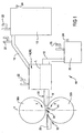
- Figure 1 is a schematic representation of a twin roll casting installation for use in the present invention;
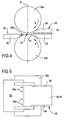
- Figures 2 and 3 show in side sectional view and plan view, respectively, a tundish/nozzle arrangement for the installation of Figure 1;
- Figures 4 and 5 show in side elevation and partial plan view, respectively, a nozzle/roll arrangement for the installation of Figure 1;
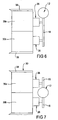
- Figures 6 to 8 show alternative modular nozzle arrangements suitable for an installation as in Figure 1;
- Figure 9 shows on an enlarged scale details relating to magnesium alloy solidification in use of an installation as in Figure 1;
- Figure 10 shows an improved form of nozzle suitable for use in the present invention;
- Figure 11 is a sectional view, taken on line XI-XI of Figure 10; and
- Figure 12 corresponds to Figure 10, but shows an alternative form of nozzle.
- In the schematic representation of Figure 1, the
installation 10 has afurnace 12 for maintaining a supply of molten magnesium alloy, and atundish enclosure 14. The alloy is able to flow as required fromfurnace 12 totundish enclosure 14 viatransfer supply tube 16 under an arrangement operable to maintain a substantially constant head of alloy inenclosure 14. Overflow alloy is able to flow fromenclosure 14 viatube 18, for collection incontainer 20. For each offurnace 10,enclosure 14,container 20 andtube 16, there is arespective inlet connector 22 by which a gas, for maintaining a protective atmosphere as detailed earlier herein, is able to be supplied from a suitable source (not shown). Each offurnace 12 andcontainer 20 has anoutlet connector 24 by which the gas is able to discharge for flow to a recovery vessel (not shown). - A form of
tundish 26 forenclosure 14 is shown in Figures 2 and 3.Tundish 26 has front andrear walls side walls 26c and a base 26d which together define achamber 28.Tundish 26 also has a cover (not shown) and atransverse baffle 30 which extends betweenwalls 26c but has its lower edge spaced from base 26d.Baffle 30 thus divideschamber 28 into arear portion 28a and aforward portion 28b. -
Installation 10 also includes anozzle 30 and aroll arrangement 32.Nozzle 30 extends forwardly fromwall 26a oftundish 26, and into a gap between upper andlower rolls arrangement 32. Therolls Arrangement 32 also includes an exit table orconveyor 35 on the side ofrolls nozzle 30. - The arrangement of Figures 2 and 3 and that of Figures 4 and 5 show alternative forms of
nozzle 30. Corresponding parts of these have the same reference numeral. In each case, thenozzle 30 has horizontally disposed, vertically spaced upper andlower plates opposite side plates 38. Analloy flow cavity 39 extends throughnozzle 30 and is defined byhorizontal plates side plates 38. Alloy intundish 26 is able to flow intonozzle 30 through anopening 40 in thefront wall 26a oftundish 26, with alloy able to discharge betweenrolls elongate outlet 42 along the edge ofplates tundish 26. As seen most clearly in Figures 2 and 4,plates side plate 38 are tapered so as to be able to extend close to each ofrolls outlet 42 is set back from a plane P containing the axes ofrolls chamber 44 is defined betweennozzle 30 and rolls 32a,32b. - With use of
installation 10,tundish 26 andnozzle 30 initially are pre-heated to temperature levels detailed earlier herein. For this purpose, a hot air gun 46 (shown in Figures 2 and 3) is able to be inserted into anopening 48 inrear wall 26b oftundish 26. When those temperature levels are achieved,gun 46 is retracted andopening 48 is closed. Molten alloy then is caused to flow fromfurnace 12, alongtube 16 and intotundish 26. Alloy intundish 26 is maintained at a required level, shown by broken line L in Figures 1 and 2, above a horizontal plane represented by line M through the centre ofnozzle outlet 42 and the bite or nip 34 ofrolls connectors 22. The atmosphere is maintained at a pressure slightly above atmospheric pressure, with over-flow gas being collected fromconnectors 24. - From
tundish 26, the alloy flows at a controlled rate through opening 40 tocavity 39 ofnozzle 30. Fromcavity 39, the alloy discharges through the length ofoutlet 42, intochamber 44, and then through the bite or nip 34 betweenrolls rolls chamber 44 due to the cooling effect ofrolls openings 35a adjacent to its edge nearer torolls strip 50, to further cool the strip and assist its movement onto table 35. - Figures 6 and 7 show alternative arrangements in which
plates nozzle 30 are provided by twosimilar modules respective tundish 26, with each tundish receiving alloy from afurnace 12 via a common tube 16 (Figure 6) or a respective tube 16 (Figure 7). - Figure 8 is similar to Figure 6. However, rather than one pair of modules receiving alloy via a
common tube 16, there are two pairs of modules, with each pair having arespective tube 16 common to its modules. - Turning now to Figure 9, the planes P and M are shown. The spacing S between plane P and a plane N parallel to plane P and extending across
outlet 42 ofnozzle 30, defines the horizontal extent ofchamber 44. That spacing is referred to as the set-back, while the height of line L (see Figures 1 and 2), above plane M is referred to as the melt head. As detailed earlier herein, the set-back, the melt head, the speed of rotation ofrolls rolls outlet 42 and its respective contact at 52a,52b along each ofrolls roll contact lines lines rolls lines - Figures 10 and 11 show a
nozzle 130 having atop plate 136, abottom plate 137 andside plates 138. At their forward edges, plates define anelongate nozzle outlet 142. Thelower plate 137 has aforward edge 137a which extends linearly betweenplates 138. In a normal arrangement,top plate 136 would have a corresponding edge, but strip cast with such normal arrangement would have a central region which is hotter than edge regions. To avoid this,top plate 136 has an edge which has acentral region 136a which is recessed rearwardly fromrespective edge regions 136b thereof. This arrangement, as detailed earlier herein, enables temperature variation across the width of cast strip to be reduced, with adverse consequences of the variation reduced or avoided. - The arrangement of Figure 12 will be understood from the description of Figures 10 and 11. In this instance, the forward edge of
top plate 136 is set back at twocentral regions 136a betweenedge regions 136b, with there being a mid-region 136c between the tworegions 136a. This arrangement is suitable where more complex temperature variation results from internal spacers between plates 136,137. In the case of Figure 11, there may be two central spacers, tending to cause two central hot zones separated by a mid-zone intermediate in temperature between the hot zones and the cooler edge zones. - Finally, it is to be understood that various alterations, modifications and/or additions may be introduced into the constructions and arrangements of parts previously described without departing from the scope of the invention, as defined by the appended claims.
maintaining heat energy extraction by the cooled rolls in step (c) at a level sufficient to maintain alloy strip issuing from the bite at a surface temperature below about 400°C;
whereby the hot rolled alloy strip is substantially free of cracks and has good surface quality.
Claims (27)
- A process for the production of magnesium alloy strip, by twin roll casting, wherein the process includes the steps of:(a) passing molten alloy from a source of supply to a feeding device;(b) feeding molten alloy from the feeding device through a nozzle to a chamber formed between an elongate outlet of the nozzle and a pair of substantially parallel rolls which are spaced one above the other to define a bite therebetween;(c) rotating said rolls in opposite directions whereby alloy is drawn from the chamber through the bite simultaneously with the feeding of step (b); and(d) flowing coolant fluid through each roll during the rotating step (c) to provide internal cooling of the rolls and thereby cooling alloy received in the chamber by heat energy extraction by the cooled rolls whereby substantially complete solidification of the magnesium alloy is achieved in the chamber prior to alloy passing through the bite defined between rolls and issuing therefrom as hot rolled alloy strip;and wherein the process further includes:- maintaining alloy held at the source at a temperature sufficient to maintain alloy in the feed device at a superheated temperature above its liquidus temperature for the alloy;- maintaining a depth of molten alloy in the feed device at a sufficient, controlled, substantially constant height of molten alloy above a centreline of the bite in a plane containing the axes of the rolls; and- maintaining heat energy extraction by the cooled rolls in step (c) at a level sufficient to maintain alloy strip issuing from the bite at a surface temperature below about 400°C;whereby the hot rolled alloy strip is substantially free of cracks and has good surface quality.
- The process of claim 1, wherein the alloy held at the source is at a temperature sufficient to maintain alloy in the feed device at a temperature of from about 15°C to about 60°C above the liquidus temperature for the alloy.
- The process of claim 1 or claim 2, wherein the level of heat energy extracted in cooling step (c) is sufficient to maintain said surface temperature substantially below 400°C.
- The process of claim 1 or claim 2, wherein the level of heat energy extraction in step (c) is sufficient to maintain said surface temperature at from about 180°C to about 300°C.
- The process of claim 3 or clam 4, wherein said surface temperature is not less than about 85°C below the solidus temperature for the alloy.
- The process of any one of claims 1 to 5, wherein said rolls apply a specific load to solidified alloy passing through the bite of from about 2 to about 500 kg. per mm of roll length.
- The process of claim 6, wherein the specific load is from about 100 to about 500 kg. per mm of roll length.
- The process of claim 6 or claim 7, wherein the specific load applied results in a thickness reduction in the hot rolled strip of from about 4% to 9%.
- The process of any one of claims 1 to 8, wherein over an initial part of a setback distance from the outlet of the nozzle to the plane containing the axes of the rolls, the alloy maintains a respective convex meniscus between the outlet of the nozzle and the surface of each roll.
- The process of claim 9, wherein each meniscus extends from the outlet of the nozzle by up to about 35% of said setback distance.
- The process of claim 10, wherein each meniscus extends from the outlet of the nozzle by from 10% to 30% of the setback distance.
- The process of any one of claims 1 to 11, wherein full solidification between upper and lower surfaces of the alloy is achieved in advance of the final 5% to 15% of the setback distance from the outlet of the nozzle to said plane containing the axes of the rolls.
- The process of any one of claims 1 to 12, wherein prior to step (a), each of the feed device and nozzle is preheated close to a required operating temperature.
- The process of claim 13, wherein the preheating is achieved by blowing hot air through the feed device and the nozzle.
- The process of claim 13 or claim 14, wherein the feed device is preheated to a temperature of from about 500°C to about 655°C, and the nozzle is preheated to a temperature of from about 200°C to 400°C.
- The process of any one of claims 1 to 15, wherein in the feeding step (b) the alloy is fed from a central region of the outlet of the nozzle which is a slight distance upstream, relative to the direction of alloy flow through the nozzle, with respect to alloy feed from laterally outer regions of the outlet, whereby variation in temperature across the width of the hot rolled strip is reduced or substantially eliminated.
- The process of claim 16, wherein said slight distance is less than about 7mm.
- The process of any one of claims 1 to 17, wherein a protective atmosphere is maintained over molten alloy to safeguard against oxidation and risk of fire, and wherein the atmosphere includes a minor proportion of a suitable hydrofluorocarbon.
- The process of claim 18, wherein the hydrofluorocarbon is 1,1,1,2-tetrafluoroethane.
- The process of claim 18 or claim 19, wherein the hydrofluorocarbon is present in the atmosphere at from about 2 to 6 volume %.
- The process of any one of claims 18 to 20, wherein the atmosphere in which the hydrofluorocarbon is provided comprises a SF6/dry air mixture.
- Magnesium alloy strip produced by the process of any one of claims 1 to 21, wherein the strip as cast has a microstructure having secondary dendritic arm spacing of primary magnesium of about 5 to 15µm, and a substantially uniform distribution of intermetallic secondary phases.
- The magnesium alloy strip of claim 22, wherein particles of said intermetallic secondary phases are about 1µm in size.
- The magnesium alloy strip of claim 22 or claim 23, wherein the microstructure has equi-axed alpha magnesium dendrites across the thickness of the strip.
- The process of any one of claims 1 to 24, wherein said step of maintaining the depth of molten alloy in the feed device provides a substantially constant height of molten alloy above the centreline of the bite of from about 5mm to about 22mm.
- The process of claim 25, wherein said alloy has a lower level of alloy element addition and said substantially constant height is from 5mm to 10mm.
- The process of claim 25, wherein said alloy has a higher level of alloy element addition and said substantially constant height is from 7mm to 22mm.
Applications Claiming Priority (3)
| Application Number | Priority Date | Filing Date | Title |
|---|---|---|---|
| AU2002951075 | 2002-08-29 | ||
| AU2002951075A AU2002951075A0 (en) | 2002-08-29 | 2002-08-29 | Twin roll casting of magnesium and magnesium alloys |
| PCT/AU2003/001097 WO2004020126A1 (en) | 2002-08-29 | 2003-08-27 | Twin roll casting of magnesium and magnesium alloys |
Publications (3)
| Publication Number | Publication Date |
|---|---|
| EP1539404A1 EP1539404A1 (en) | 2005-06-15 |
| EP1539404A4 EP1539404A4 (en) | 2006-05-10 |
| EP1539404B1 true EP1539404B1 (en) | 2007-11-14 |
Family
ID=27810145
Family Applications (1)
| Application Number | Title | Priority Date | Filing Date |
|---|---|---|---|
| EP03790551A Expired - Lifetime EP1539404B1 (en) | 2002-08-29 | 2003-08-27 | Twin roll casting of magnesium and magnesium alloys |
Country Status (21)
| Country | Link |
|---|---|
| US (1) | US7028749B2 (en) |
| EP (1) | EP1539404B1 (en) |
| JP (1) | JP4637580B2 (en) |
| KR (1) | KR101186225B1 (en) |
| CN (1) | CN1321763C (en) |
| AT (1) | ATE378125T1 (en) |
| AU (2) | AU2002951075A0 (en) |
| BR (1) | BR0313843A (en) |
| CA (1) | CA2497046C (en) |
| DE (1) | DE60317527T2 (en) |
| ES (1) | ES2295680T3 (en) |
| HR (1) | HRP20050286A2 (en) |
| MX (1) | MXPA05002223A (en) |
| MY (1) | MY136118A (en) |
| NO (1) | NO20051050L (en) |
| RS (1) | RS20050245A (en) |
| RU (1) | RU2319576C2 (en) |
| TW (1) | TWI300729B (en) |
| UA (1) | UA79005C2 (en) |
| WO (1) | WO2004020126A1 (en) |
| ZA (1) | ZA200501762B (en) |
Cited By (2)
| Publication number | Priority date | Publication date | Assignee | Title |
|---|---|---|---|---|
| US10957942B2 (en) | 2016-09-14 | 2021-03-23 | Wirtz Manufacturing Co., Inc. | Continuous lead strip casting line, caster, and nozzle |
| US10960461B2 (en) | 2016-09-14 | 2021-03-30 | Wirtz Manufacturing Co., Inc. | Continuous lead strip casting line, caster, and nozzle |
Families Citing this family (25)
| Publication number | Priority date | Publication date | Assignee | Title |
|---|---|---|---|---|
| CA2572480C (en) * | 2004-06-30 | 2011-09-06 | Sumitomo Electric Industries, Ltd. | Producing method for magnesium alloy material |
| JP4517386B2 (en) * | 2004-06-30 | 2010-08-04 | 住友電気工業株式会社 | Casting nozzle |
| KR101193064B1 (en) | 2004-12-24 | 2012-10-22 | 재단법인 포항산업과학연구원 | System of casting operation in manufacturing Mg strip with horizontal twin roll strip casting apparatus |
| US9968994B2 (en) | 2005-03-24 | 2018-05-15 | Sumitomo Electric Industries, Ltd. | Casting nozzle |
| JP4721095B2 (en) | 2005-03-24 | 2011-07-13 | 住友電気工業株式会社 | Casting nozzle |
| JP4627045B2 (en) * | 2005-04-27 | 2011-02-09 | セントラル硝子株式会社 | Metal production protective gas |
| CN100366351C (en) * | 2006-01-26 | 2008-02-06 | 鞍山科技大学 | On-line oil bath heat treatment twin-roll casting method and device |
| US8661708B2 (en) | 2006-11-06 | 2014-03-04 | Wookyung Tech Co., Ltd. | Crampon for golf shoes and climbing irons |
| US8122940B2 (en) * | 2008-07-16 | 2012-02-28 | Fata Hunter, Inc. | Method for twin roll casting of aluminum clad magnesium |
| US7888158B1 (en) * | 2009-07-21 | 2011-02-15 | Sears Jr James B | System and method for making a photovoltaic unit |
| JP5939372B2 (en) * | 2010-03-30 | 2016-06-22 | 住友電気工業株式会社 | Coil material and manufacturing method thereof |
| RU2438828C2 (en) * | 2010-04-08 | 2012-01-10 | Открытое акционерное общество Акционерная холдинговая компания "Всероссийский научно-исследовательский и проектно-конструкторский институт металлургического машиностроения имени академика Целикова" (ОАО АХК "ВНИИМЕТМАШ") | Method of producing composite metal strip |
| RU2443504C2 (en) * | 2010-04-08 | 2012-02-27 | Открытое акционерное общество Акционерная холдинговая компания "Всероссийский научно-исследовательский и проектно-конструкторский институт металлургического машиностроения имени академика Целикова" (ОАО АХК "ВНИИМЕТМАШ") | Method of producing metal strip |
| CN101837368B (en) * | 2010-04-27 | 2012-02-01 | 新星化工冶金材料(深圳)有限公司 | Continuous casting and rolling molding method for magnesium alloy plate |
| DE102012209568B4 (en) | 2012-06-06 | 2016-01-14 | Technische Universität Bergakademie Freiberg | Method and device for casting rolls of magnesium wires |
| KR101658921B1 (en) | 2015-12-03 | 2016-09-22 | 이인영 | Method for manufacturing magnesium alloy billet of extrusion |
| CN107398535A (en) * | 2016-05-20 | 2017-11-28 | 核工业西南物理研究院 | A kind of novel magnesium alloy spun furnace |
| CN106493340B (en) * | 2016-11-29 | 2018-10-26 | 太原科技大学 | A kind of roll-casting of magnesium alloy turns liquid system and device |
| WO2018165316A1 (en) * | 2017-03-08 | 2018-09-13 | Southwire Company, Llc | Grain refining with direct vibrational coupling |
| CN107159855A (en) * | 2017-06-26 | 2017-09-15 | 太原科技大学 | Roll-casting of magnesium alloy case before tilting casting and rolling machine-lip system |
| EP3829789B1 (en) * | 2018-07-30 | 2025-04-02 | Wirtz Manufacturing Co., Inc. | Continuous lead strip casting line with caster and nozzle |
| WO2021001495A1 (en) * | 2019-07-03 | 2021-01-07 | Hydro Aluminium Rolled Products Gmbh | Molten metal guide for strip casting systems |
| CN114226663B (en) * | 2020-09-09 | 2023-01-20 | 上海交通大学 | Casting device and casting method |
| CN112264592B (en) * | 2020-09-24 | 2022-04-08 | 中铝材料应用研究院有限公司 | High-speed mechanical stirring casting-rolling device and method for magnesium alloy thin strip |
| CN112935207B (en) * | 2021-01-29 | 2022-07-01 | 吉林大学 | Multifunctional double-roller casting and rolling equipment and application thereof |
Family Cites Families (23)
| Publication number | Priority date | Publication date | Assignee | Title |
|---|---|---|---|---|
| US3405757A (en) * | 1967-04-12 | 1968-10-15 | Harvey Aluminum Inc | Method and apparatus for continuous casting of metal between oppositely rotatable cooling rolls set generally one above the other |
| AU507351B2 (en) * | 1974-12-23 | 1980-02-14 | Hunter Engineering Co. Inc. | Roll casting |
| JPS60213340A (en) * | 1984-04-05 | 1985-10-25 | Onkyo Corp | Manufacturing method of Mg-based alloy diaphragm |
| GB8702837D0 (en) * | 1987-02-09 | 1987-03-18 | Alcan Int Ltd | Casting al-li alloys |
| JPH07115132B2 (en) * | 1988-02-05 | 1995-12-13 | 株式会社神戸製鋼所 | Casting method of Al-Mg alloy with twin rolls |
| ES2090301T3 (en) * | 1990-11-15 | 1996-10-16 | Du Pont | PROCEDURE FOR FIRE FIGHTING. |
| RU2009005C1 (en) * | 1992-12-17 | 1994-03-15 | Ленинградский фольгопрокатный завод | Method of producing sheet slab from aluminium and its alloys |
| US5439047A (en) * | 1994-02-07 | 1995-08-08 | Eckert; C. Edward | Heated nozzle for continuous caster |
| JP3262672B2 (en) * | 1994-03-17 | 2002-03-04 | スカイアルミニウム株式会社 | Starting method in twin roll casting of aluminum alloy |
| JPH105959A (en) * | 1996-06-27 | 1998-01-13 | Mitsubishi Heavy Ind Ltd | Continuous casting equipment and continuous casting method |
| JP3703919B2 (en) * | 1996-09-25 | 2005-10-05 | 古河スカイ株式会社 | Method for producing directly cast and rolled sheet of Al-Mg-Si alloy |
| JPH10130767A (en) * | 1996-10-30 | 1998-05-19 | Furukawa Electric Co Ltd:The | High formability Al-Mg-Si alloy sheet and method for producing the same |
| JP3387362B2 (en) | 1997-05-23 | 2003-03-17 | 宇部興産株式会社 | Metal surface level detection method for molten metal or alloy |
| WO1999022892A1 (en) * | 1997-10-31 | 1999-05-14 | Fata Hunter, Inc. | Adjustable molten metal feed system |
| CN1063688C (en) * | 1998-08-28 | 2001-03-28 | 重庆钢铁(集团)有限责任公司 | Dual-roller conticaster of thin sheet billet |
| JP2000212607A (en) * | 1999-01-26 | 2000-08-02 | Matsushita Electric Ind Co Ltd | Method and apparatus for producing chip for thixomolding molding machine |
| JP2004514097A (en) * | 2000-11-15 | 2004-05-13 | フェデラル−モーグル コーポレイション | Unplated aluminum-based bearing alloy with an intermediate layer with improved performance |
| CA2438720C (en) * | 2001-04-09 | 2008-01-29 | Sumitomo Electric Industries, Ltd. | Magnesium alloy material and method of manufacturing the alloy material |
| EP1440177A1 (en) * | 2001-09-25 | 2004-07-28 | Assan Demir VE SAC Sanayi A.S. | Process of producing 5xxx series aluminum alloys with high mechanical properties through twin-roll casting |
| JP2003266150A (en) * | 2002-03-13 | 2003-09-24 | Ishikawajima Harima Heavy Ind Co Ltd | Method and apparatus for producing magnesium alloy sheet |
| JP3680818B2 (en) * | 2002-05-23 | 2005-08-10 | 住友金属工業株式会社 | Magnesium alloy sheet manufacturing method and apparatus |
| ES2423825T3 (en) * | 2002-08-21 | 2013-09-24 | Alcoa Inc. | Nonferrous Metal Casting |
| JP3503898B1 (en) * | 2003-03-07 | 2004-03-08 | 権田金属工業株式会社 | Method and apparatus for manufacturing magnesium metal sheet |
-
2002
- 2002-08-29 AU AU2002951075A patent/AU2002951075A0/en not_active Abandoned
-
2003
- 2003-08-27 ES ES03790551T patent/ES2295680T3/en not_active Expired - Lifetime
- 2003-08-27 UA UAA200501578A patent/UA79005C2/en unknown
- 2003-08-27 BR BR0313843-7A patent/BR0313843A/en not_active Application Discontinuation
- 2003-08-27 RS YUP-2005/0245A patent/RS20050245A/en unknown
- 2003-08-27 DE DE60317527T patent/DE60317527T2/en not_active Expired - Lifetime
- 2003-08-27 RU RU2005108672/02A patent/RU2319576C2/en not_active IP Right Cessation
- 2003-08-27 HR HR20050286A patent/HRP20050286A2/en not_active Application Discontinuation
- 2003-08-27 CN CNB038232642A patent/CN1321763C/en not_active Expired - Lifetime
- 2003-08-27 CA CA2497046A patent/CA2497046C/en not_active Expired - Lifetime
- 2003-08-27 JP JP2004531289A patent/JP4637580B2/en not_active Expired - Fee Related
- 2003-08-27 MX MXPA05002223A patent/MXPA05002223A/en active IP Right Grant
- 2003-08-27 EP EP03790551A patent/EP1539404B1/en not_active Expired - Lifetime
- 2003-08-27 WO PCT/AU2003/001097 patent/WO2004020126A1/en not_active Ceased
- 2003-08-27 AU AU2003254397A patent/AU2003254397B2/en not_active Expired
- 2003-08-27 AT AT03790551T patent/ATE378125T1/en active
- 2003-08-27 KR KR1020057003249A patent/KR101186225B1/en not_active Expired - Lifetime
- 2003-08-28 TW TW092123702A patent/TWI300729B/en not_active IP Right Cessation
- 2003-08-29 MY MYPI20033286A patent/MY136118A/en unknown
-
2005
- 2005-02-25 NO NO20051050A patent/NO20051050L/en not_active Application Discontinuation
- 2005-02-28 US US11/068,514 patent/US7028749B2/en not_active Expired - Lifetime
- 2005-03-01 ZA ZA200501762A patent/ZA200501762B/en unknown
Cited By (2)
| Publication number | Priority date | Publication date | Assignee | Title |
|---|---|---|---|---|
| US10957942B2 (en) | 2016-09-14 | 2021-03-23 | Wirtz Manufacturing Co., Inc. | Continuous lead strip casting line, caster, and nozzle |
| US10960461B2 (en) | 2016-09-14 | 2021-03-30 | Wirtz Manufacturing Co., Inc. | Continuous lead strip casting line, caster, and nozzle |
Also Published As
| Publication number | Publication date |
|---|---|
| JP4637580B2 (en) | 2011-02-23 |
| ES2295680T3 (en) | 2008-04-16 |
| BR0313843A (en) | 2005-07-12 |
| ZA200501762B (en) | 2006-05-31 |
| CN1684784A (en) | 2005-10-19 |
| KR20050059111A (en) | 2005-06-17 |
| DE60317527D1 (en) | 2007-12-27 |
| MY136118A (en) | 2008-08-29 |
| US20050236135A1 (en) | 2005-10-27 |
| RU2319576C2 (en) | 2008-03-20 |
| AU2002951075A0 (en) | 2002-09-12 |
| TW200404629A (en) | 2004-04-01 |
| CA2497046A1 (en) | 2004-03-11 |
| US7028749B2 (en) | 2006-04-18 |
| NO20051050L (en) | 2005-04-13 |
| AU2003254397B2 (en) | 2007-05-17 |
| RU2005108672A (en) | 2005-10-27 |
| CN1321763C (en) | 2007-06-20 |
| AU2003254397A1 (en) | 2004-03-19 |
| ATE378125T1 (en) | 2007-11-15 |
| EP1539404A1 (en) | 2005-06-15 |
| TWI300729B (en) | 2008-09-11 |
| WO2004020126A1 (en) | 2004-03-11 |
| DE60317527T2 (en) | 2008-10-30 |
| UA79005C2 (en) | 2007-05-10 |
| EP1539404A4 (en) | 2006-05-10 |
| KR101186225B1 (en) | 2012-09-28 |
| CA2497046C (en) | 2011-04-19 |
| HRP20050286A2 (en) | 2005-10-31 |
| JP2005536358A (en) | 2005-12-02 |
| MXPA05002223A (en) | 2005-07-05 |
| RS20050245A (en) | 2007-06-04 |
Similar Documents
| Publication | Publication Date | Title |
|---|---|---|
| EP1539404B1 (en) | Twin roll casting of magnesium and magnesium alloys | |
| Emley | Continuous casting of aluminium | |
| JP2005536358A5 (en) | ||
| US4166495A (en) | Ingot casting method | |
| US4515204A (en) | Continuous metal casting | |
| US4715428A (en) | Method and apparatus for direct casting of crystalline strip by radiant cooling | |
| US4911226A (en) | Method and apparatus for continuously casting strip steel | |
| US3593778A (en) | Continuous casting apparatus | |
| US2955334A (en) | Continuous casting | |
| US4678719A (en) | Method and apparatus for continuous casting of crystalline strip | |
| EP0174765B1 (en) | Method and apparatus for continuous casting of crystalline strip | |
| Lewis | The production of non-ferrous metal slab and bar by continuous-casting and rolling methods | |
| EP0174767B1 (en) | Method and apparatus for direct casting of crystalline strip by radiantly cooling | |
| US4830087A (en) | Continuous casting of thin slab ingots | |
| EP0174766B1 (en) | Method and apparatus for direct casting of crystalline strip in non-oxidizing atmosphere | |
| US6179042B1 (en) | Non-hot crack bottom block for casting aluminum ingot | |
| CA1195086A (en) | Method and apparatus for strip casting | |
| JPH0346217B2 (en) |
Legal Events
| Date | Code | Title | Description |
|---|---|---|---|
| PUAI | Public reference made under article 153(3) epc to a published international application that has entered the european phase |
Free format text: ORIGINAL CODE: 0009012 |
|
| 17P | Request for examination filed |
Effective date: 20050314 |
|
| AK | Designated contracting states |
Kind code of ref document: A1 Designated state(s): AT BE BG CH CY CZ DE DK EE ES FI FR GB GR HU IE IT LI LU MC NL PT RO SE SI SK TR |
|
| AX | Request for extension of the european patent |
Extension state: AL LT LV MK |
|
| A4 | Supplementary search report drawn up and despatched |
Effective date: 20060329 |
|
| GRAP | Despatch of communication of intention to grant a patent |
Free format text: ORIGINAL CODE: EPIDOSNIGR1 |
|
| GRAS | Grant fee paid |
Free format text: ORIGINAL CODE: EPIDOSNIGR3 |
|
| GRAA | (expected) grant |
Free format text: ORIGINAL CODE: 0009210 |
|
| AK | Designated contracting states |
Kind code of ref document: B1 Designated state(s): AT BE BG CH CY CZ DE DK EE ES FI FR GB GR HU IE IT LI LU MC NL PT RO SE SI SK TR |
|
| AX | Request for extension of the european patent |
Extension state: AL LT LV MK |
|
| REG | Reference to a national code |
Ref country code: GB Ref legal event code: FG4D |
|
| REG | Reference to a national code |
Ref country code: CH Ref legal event code: EP |
|
| REG | Reference to a national code |
Ref country code: IE Ref legal event code: FG4D |
|
| REF | Corresponds to: |
Ref document number: 60317527 Country of ref document: DE Date of ref document: 20071227 Kind code of ref document: P |
|
| REG | Reference to a national code |
Ref country code: ES Ref legal event code: FG2A Ref document number: 2295680 Country of ref document: ES Kind code of ref document: T3 |
|
| PG25 | Lapsed in a contracting state [announced via postgrant information from national office to epo] |
Ref country code: SE Free format text: LAPSE BECAUSE OF FAILURE TO SUBMIT A TRANSLATION OF THE DESCRIPTION OR TO PAY THE FEE WITHIN THE PRESCRIBED TIME-LIMIT Effective date: 20080214 Ref country code: LI Free format text: LAPSE BECAUSE OF FAILURE TO SUBMIT A TRANSLATION OF THE DESCRIPTION OR TO PAY THE FEE WITHIN THE PRESCRIBED TIME-LIMIT Effective date: 20071114 Ref country code: CH Free format text: LAPSE BECAUSE OF FAILURE TO SUBMIT A TRANSLATION OF THE DESCRIPTION OR TO PAY THE FEE WITHIN THE PRESCRIBED TIME-LIMIT Effective date: 20071114 |
|
| PG25 | Lapsed in a contracting state [announced via postgrant information from national office to epo] |
Ref country code: FI Free format text: LAPSE BECAUSE OF FAILURE TO SUBMIT A TRANSLATION OF THE DESCRIPTION OR TO PAY THE FEE WITHIN THE PRESCRIBED TIME-LIMIT Effective date: 20071114 Ref country code: SI Free format text: LAPSE BECAUSE OF FAILURE TO SUBMIT A TRANSLATION OF THE DESCRIPTION OR TO PAY THE FEE WITHIN THE PRESCRIBED TIME-LIMIT Effective date: 20071114 Ref country code: BG Free format text: LAPSE BECAUSE OF FAILURE TO SUBMIT A TRANSLATION OF THE DESCRIPTION OR TO PAY THE FEE WITHIN THE PRESCRIBED TIME-LIMIT Effective date: 20080214 |
|
| REG | Reference to a national code |
Ref country code: CH Ref legal event code: PL |
|
| PG25 | Lapsed in a contracting state [announced via postgrant information from national office to epo] |
Ref country code: DK Free format text: LAPSE BECAUSE OF FAILURE TO SUBMIT A TRANSLATION OF THE DESCRIPTION OR TO PAY THE FEE WITHIN THE PRESCRIBED TIME-LIMIT Effective date: 20071114 Ref country code: CZ Free format text: LAPSE BECAUSE OF FAILURE TO SUBMIT A TRANSLATION OF THE DESCRIPTION OR TO PAY THE FEE WITHIN THE PRESCRIBED TIME-LIMIT Effective date: 20071114 |
|
| ET | Fr: translation filed | ||
| PG25 | Lapsed in a contracting state [announced via postgrant information from national office to epo] |
Ref country code: SK Free format text: LAPSE BECAUSE OF FAILURE TO SUBMIT A TRANSLATION OF THE DESCRIPTION OR TO PAY THE FEE WITHIN THE PRESCRIBED TIME-LIMIT Effective date: 20071114 Ref country code: BE Free format text: LAPSE BECAUSE OF FAILURE TO SUBMIT A TRANSLATION OF THE DESCRIPTION OR TO PAY THE FEE WITHIN THE PRESCRIBED TIME-LIMIT Effective date: 20071114 Ref country code: RO Free format text: LAPSE BECAUSE OF FAILURE TO SUBMIT A TRANSLATION OF THE DESCRIPTION OR TO PAY THE FEE WITHIN THE PRESCRIBED TIME-LIMIT Effective date: 20071114 |
|
| PLBE | No opposition filed within time limit |
Free format text: ORIGINAL CODE: 0009261 |
|
| STAA | Information on the status of an ep patent application or granted ep patent |
Free format text: STATUS: NO OPPOSITION FILED WITHIN TIME LIMIT |
|
| PG25 | Lapsed in a contracting state [announced via postgrant information from national office to epo] |
Ref country code: PT Free format text: LAPSE BECAUSE OF FAILURE TO SUBMIT A TRANSLATION OF THE DESCRIPTION OR TO PAY THE FEE WITHIN THE PRESCRIBED TIME-LIMIT Effective date: 20080414 |
|
| 26N | No opposition filed |
Effective date: 20080815 |
|
| PG25 | Lapsed in a contracting state [announced via postgrant information from national office to epo] |
Ref country code: GR Free format text: LAPSE BECAUSE OF FAILURE TO SUBMIT A TRANSLATION OF THE DESCRIPTION OR TO PAY THE FEE WITHIN THE PRESCRIBED TIME-LIMIT Effective date: 20080215 |
|
| PG25 | Lapsed in a contracting state [announced via postgrant information from national office to epo] |
Ref country code: MC Free format text: LAPSE BECAUSE OF NON-PAYMENT OF DUE FEES Effective date: 20080831 |
|
| PG25 | Lapsed in a contracting state [announced via postgrant information from national office to epo] |
Ref country code: EE Free format text: LAPSE BECAUSE OF FAILURE TO SUBMIT A TRANSLATION OF THE DESCRIPTION OR TO PAY THE FEE WITHIN THE PRESCRIBED TIME-LIMIT Effective date: 20071114 |
|
| PG25 | Lapsed in a contracting state [announced via postgrant information from national office to epo] |
Ref country code: CY Free format text: LAPSE BECAUSE OF FAILURE TO SUBMIT A TRANSLATION OF THE DESCRIPTION OR TO PAY THE FEE WITHIN THE PRESCRIBED TIME-LIMIT Effective date: 20071114 Ref country code: IE Free format text: LAPSE BECAUSE OF NON-PAYMENT OF DUE FEES Effective date: 20080827 |
|
| PG25 | Lapsed in a contracting state [announced via postgrant information from national office to epo] |
Ref country code: LU Free format text: LAPSE BECAUSE OF NON-PAYMENT OF DUE FEES Effective date: 20080827 Ref country code: HU Free format text: LAPSE BECAUSE OF FAILURE TO SUBMIT A TRANSLATION OF THE DESCRIPTION OR TO PAY THE FEE WITHIN THE PRESCRIBED TIME-LIMIT Effective date: 20080515 |
|
| PGFP | Annual fee paid to national office [announced via postgrant information from national office to epo] |
Ref country code: ES Payment date: 20110915 Year of fee payment: 9 Ref country code: TR Payment date: 20110805 Year of fee payment: 9 Ref country code: AT Payment date: 20110726 Year of fee payment: 9 |
|
| REG | Reference to a national code |
Ref country code: AT Ref legal event code: MM01 Ref document number: 378125 Country of ref document: AT Kind code of ref document: T Effective date: 20120827 |
|
| PG25 | Lapsed in a contracting state [announced via postgrant information from national office to epo] |
Ref country code: AT Free format text: LAPSE BECAUSE OF NON-PAYMENT OF DUE FEES Effective date: 20120827 |
|
| REG | Reference to a national code |
Ref country code: ES Ref legal event code: FD2A Effective date: 20131022 |
|
| PG25 | Lapsed in a contracting state [announced via postgrant information from national office to epo] |
Ref country code: ES Free format text: LAPSE BECAUSE OF NON-PAYMENT OF DUE FEES Effective date: 20120828 Ref country code: TR Free format text: LAPSE BECAUSE OF NON-PAYMENT OF DUE FEES Effective date: 20120827 |
|
| PGFP | Annual fee paid to national office [announced via postgrant information from national office to epo] |
Ref country code: NL Payment date: 20140809 Year of fee payment: 12 |
|
| REG | Reference to a national code |
Ref country code: DE Ref legal event code: R082 Ref document number: 60317527 Country of ref document: DE Representative=s name: ANDRAE WESTENDORP PATENTANWAELTE PARTNERSCHAFT, DE |
|
| PGFP | Annual fee paid to national office [announced via postgrant information from national office to epo] |
Ref country code: IT Payment date: 20140820 Year of fee payment: 12 |
|
| PG25 | Lapsed in a contracting state [announced via postgrant information from national office to epo] |
Ref country code: IT Free format text: LAPSE BECAUSE OF NON-PAYMENT OF DUE FEES Effective date: 20150827 |
|
| REG | Reference to a national code |
Ref country code: NL Ref legal event code: MM Effective date: 20150901 |
|
| PG25 | Lapsed in a contracting state [announced via postgrant information from national office to epo] |
Ref country code: NL Free format text: LAPSE BECAUSE OF NON-PAYMENT OF DUE FEES Effective date: 20150901 |
|
| REG | Reference to a national code |
Ref country code: FR Ref legal event code: PLFP Year of fee payment: 14 |
|
| REG | Reference to a national code |
Ref country code: FR Ref legal event code: PLFP Year of fee payment: 15 |
|
| REG | Reference to a national code |
Ref country code: FR Ref legal event code: PLFP Year of fee payment: 16 |
|
| REG | Reference to a national code |
Ref country code: DE Ref legal event code: R082 Ref document number: 60317527 Country of ref document: DE |
|
| PGFP | Annual fee paid to national office [announced via postgrant information from national office to epo] |
Ref country code: GB Payment date: 20220818 Year of fee payment: 20 Ref country code: DE Payment date: 20220621 Year of fee payment: 20 |
|
| PGFP | Annual fee paid to national office [announced via postgrant information from national office to epo] |
Ref country code: FR Payment date: 20220822 Year of fee payment: 20 |
|
| P01 | Opt-out of the competence of the unified patent court (upc) registered |
Effective date: 20230524 |
|
| REG | Reference to a national code |
Ref country code: DE Ref legal event code: R071 Ref document number: 60317527 Country of ref document: DE |
|
| REG | Reference to a national code |
Ref country code: GB Ref legal event code: PE20 Expiry date: 20230826 |
|
| PG25 | Lapsed in a contracting state [announced via postgrant information from national office to epo] |
Ref country code: GB Free format text: LAPSE BECAUSE OF EXPIRATION OF PROTECTION Effective date: 20230826 |