EP1539273B1 - Device for drug delivery to animals - Google Patents
Device for drug delivery to animals Download PDFInfo
- Publication number
- EP1539273B1 EP1539273B1 EP03763376.5A EP03763376A EP1539273B1 EP 1539273 B1 EP1539273 B1 EP 1539273B1 EP 03763376 A EP03763376 A EP 03763376A EP 1539273 B1 EP1539273 B1 EP 1539273B1
- Authority
- EP
- European Patent Office
- Prior art keywords
- syringe
- fluid
- catheter
- valve
- drug delivery
- Prior art date
- Legal status (The legal status is an assumption and is not a legal conclusion. Google has not performed a legal analysis and makes no representation as to the accuracy of the status listed.)
- Expired - Lifetime
Links
Images


Classifications
-
- A—HUMAN NECESSITIES
- A61—MEDICAL OR VETERINARY SCIENCE; HYGIENE
- A61B—DIAGNOSIS; SURGERY; IDENTIFICATION
- A61B5/00—Measuring for diagnostic purposes; Identification of persons
- A61B5/14—Devices for taking samples of blood ; Measuring characteristics of blood in vivo, e.g. gas concentration within the blood, pH-value of blood
- A61B5/1405—Devices for taking blood samples
- A61B5/1427—Multiple blood sampling, e.g. at periodic or pre-established intervals
-
- A—HUMAN NECESSITIES
- A61—MEDICAL OR VETERINARY SCIENCE; HYGIENE
- A61M—DEVICES FOR INTRODUCING MEDIA INTO, OR ONTO, THE BODY; DEVICES FOR TRANSDUCING BODY MEDIA OR FOR TAKING MEDIA FROM THE BODY; DEVICES FOR PRODUCING OR ENDING SLEEP OR STUPOR
- A61M5/00—Devices for bringing media into the body in a subcutaneous, intra-vascular or intramuscular way; Accessories therefor, e.g. filling or cleaning devices, arm-rests
- A61M5/14—Infusion devices, e.g. infusing by gravity; Blood infusion; Accessories therefor
- A61M5/142—Pressure infusion, e.g. using pumps
- A61M5/145—Pressure infusion, e.g. using pumps using pressurised reservoirs, e.g. pressurised by means of pistons
- A61M5/1452—Pressure infusion, e.g. using pumps using pressurised reservoirs, e.g. pressurised by means of pistons pressurised by means of pistons
- A61M5/1456—Pressure infusion, e.g. using pumps using pressurised reservoirs, e.g. pressurised by means of pistons pressurised by means of pistons with a replaceable reservoir comprising a piston rod to be moved into the reservoir, e.g. the piston rod is part of the removable reservoir
-
- A—HUMAN NECESSITIES
- A61—MEDICAL OR VETERINARY SCIENCE; HYGIENE
- A61B—DIAGNOSIS; SURGERY; IDENTIFICATION
- A61B5/00—Measuring for diagnostic purposes; Identification of persons
- A61B5/14—Devices for taking samples of blood ; Measuring characteristics of blood in vivo, e.g. gas concentration within the blood, pH-value of blood
-
- A—HUMAN NECESSITIES
- A61—MEDICAL OR VETERINARY SCIENCE; HYGIENE
- A61B—DIAGNOSIS; SURGERY; IDENTIFICATION
- A61B5/00—Measuring for diagnostic purposes; Identification of persons
- A61B5/15—Devices for taking samples of blood
- A61B5/150007—Details
- A61B5/150015—Source of blood
- A61B5/15003—Source of blood for venous or arterial blood
-
- A—HUMAN NECESSITIES
- A61—MEDICAL OR VETERINARY SCIENCE; HYGIENE
- A61B—DIAGNOSIS; SURGERY; IDENTIFICATION
- A61B5/00—Measuring for diagnostic purposes; Identification of persons
- A61B5/15—Devices for taking samples of blood
- A61B5/150007—Details
- A61B5/150206—Construction or design features not otherwise provided for; manufacturing or production; packages; sterilisation of piercing element, piercing device or sampling device
- A61B5/150221—Valves
-
- A—HUMAN NECESSITIES
- A61—MEDICAL OR VETERINARY SCIENCE; HYGIENE
- A61B—DIAGNOSIS; SURGERY; IDENTIFICATION
- A61B5/00—Measuring for diagnostic purposes; Identification of persons
- A61B5/15—Devices for taking samples of blood
- A61B5/150007—Details
- A61B5/150206—Construction or design features not otherwise provided for; manufacturing or production; packages; sterilisation of piercing element, piercing device or sampling device
- A61B5/150236—Pistons, i.e. cylindrical bodies that sit inside the syringe barrel, typically with an air tight seal, and slide in the barrel to create a vacuum or to expel blood
-
- A—HUMAN NECESSITIES
- A61—MEDICAL OR VETERINARY SCIENCE; HYGIENE
- A61B—DIAGNOSIS; SURGERY; IDENTIFICATION
- A61B5/00—Measuring for diagnostic purposes; Identification of persons
- A61B5/15—Devices for taking samples of blood
- A61B5/150007—Details
- A61B5/150206—Construction or design features not otherwise provided for; manufacturing or production; packages; sterilisation of piercing element, piercing device or sampling device
- A61B5/150244—Rods for actuating or driving the piston, i.e. the cylindrical body that sits inside the syringe barrel, typically with an air tight seal, and slides in the barrel to create a vacuum or to expel blood
-
- A—HUMAN NECESSITIES
- A61—MEDICAL OR VETERINARY SCIENCE; HYGIENE
- A61B—DIAGNOSIS; SURGERY; IDENTIFICATION
- A61B5/00—Measuring for diagnostic purposes; Identification of persons
- A61B5/15—Devices for taking samples of blood
- A61B5/150007—Details
- A61B5/150847—Communication to or from blood sampling device
- A61B5/150854—Communication to or from blood sampling device long distance, e.g. between patient's home and doctor's office
-
- A—HUMAN NECESSITIES
- A61—MEDICAL OR VETERINARY SCIENCE; HYGIENE
- A61B—DIAGNOSIS; SURGERY; IDENTIFICATION
- A61B5/00—Measuring for diagnostic purposes; Identification of persons
- A61B5/15—Devices for taking samples of blood
- A61B5/150007—Details
- A61B5/150847—Communication to or from blood sampling device
- A61B5/150862—Communication to or from blood sampling device intermediate range, e.g. within room or building
-
- A—HUMAN NECESSITIES
- A61—MEDICAL OR VETERINARY SCIENCE; HYGIENE
- A61B—DIAGNOSIS; SURGERY; IDENTIFICATION
- A61B5/00—Measuring for diagnostic purposes; Identification of persons
- A61B5/15—Devices for taking samples of blood
- A61B5/150007—Details
- A61B5/150847—Communication to or from blood sampling device
- A61B5/15087—Communication to or from blood sampling device short range, e.g. between console and disposable
-
- A—HUMAN NECESSITIES
- A61—MEDICAL OR VETERINARY SCIENCE; HYGIENE
- A61B—DIAGNOSIS; SURGERY; IDENTIFICATION
- A61B5/00—Measuring for diagnostic purposes; Identification of persons
- A61B5/15—Devices for taking samples of blood
- A61B5/150992—Blood sampling from a fluid line external to a patient, such as a catheter line, combined with an infusion line; blood sampling from indwelling needle sets, e.g. sealable ports, luer couplings, valves
-
- A—HUMAN NECESSITIES
- A61—MEDICAL OR VETERINARY SCIENCE; HYGIENE
- A61B—DIAGNOSIS; SURGERY; IDENTIFICATION
- A61B5/00—Measuring for diagnostic purposes; Identification of persons
- A61B5/15—Devices for taking samples of blood
- A61B5/153—Devices specially adapted for taking samples of venous or arterial blood, e.g. with syringes
-
- A—HUMAN NECESSITIES
- A61—MEDICAL OR VETERINARY SCIENCE; HYGIENE
- A61B—DIAGNOSIS; SURGERY; IDENTIFICATION
- A61B5/00—Measuring for diagnostic purposes; Identification of persons
- A61B5/15—Devices for taking samples of blood
- A61B5/155—Devices specially adapted for continuous or multiple sampling, e.g. at predetermined intervals
-
- A—HUMAN NECESSITIES
- A61—MEDICAL OR VETERINARY SCIENCE; HYGIENE
- A61M—DEVICES FOR INTRODUCING MEDIA INTO, OR ONTO, THE BODY; DEVICES FOR TRANSDUCING BODY MEDIA OR FOR TAKING MEDIA FROM THE BODY; DEVICES FOR PRODUCING OR ENDING SLEEP OR STUPOR
- A61M5/00—Devices for bringing media into the body in a subcutaneous, intra-vascular or intramuscular way; Accessories therefor, e.g. filling or cleaning devices, arm-rests
- A61M5/14—Infusion devices, e.g. infusing by gravity; Blood infusion; Accessories therefor
- A61M5/1407—Infusion of two or more substances
- A61M5/1408—Infusion of two or more substances in parallel, e.g. manifolds, sequencing valves
-
- A—HUMAN NECESSITIES
- A61—MEDICAL OR VETERINARY SCIENCE; HYGIENE
- A61M—DEVICES FOR INTRODUCING MEDIA INTO, OR ONTO, THE BODY; DEVICES FOR TRANSDUCING BODY MEDIA OR FOR TAKING MEDIA FROM THE BODY; DEVICES FOR PRODUCING OR ENDING SLEEP OR STUPOR
- A61M5/00—Devices for bringing media into the body in a subcutaneous, intra-vascular or intramuscular way; Accessories therefor, e.g. filling or cleaning devices, arm-rests
- A61M5/14—Infusion devices, e.g. infusing by gravity; Blood infusion; Accessories therefor
- A61M5/168—Means for controlling media flow to the body or for metering media to the body, e.g. drip meters, counters ; Monitoring media flow to the body
- A61M5/16804—Flow controllers
- A61M5/16827—Flow controllers controlling delivery of multiple fluids, e.g. sequencing, mixing or via separate flow-paths
-
- A—HUMAN NECESSITIES
- A61—MEDICAL OR VETERINARY SCIENCE; HYGIENE
- A61M—DEVICES FOR INTRODUCING MEDIA INTO, OR ONTO, THE BODY; DEVICES FOR TRANSDUCING BODY MEDIA OR FOR TAKING MEDIA FROM THE BODY; DEVICES FOR PRODUCING OR ENDING SLEEP OR STUPOR
- A61M2205/00—General characteristics of the apparatus
- A61M2205/11—General characteristics of the apparatus with means for preventing cross-contamination when used for multiple patients
-
- A—HUMAN NECESSITIES
- A61—MEDICAL OR VETERINARY SCIENCE; HYGIENE
- A61M—DEVICES FOR INTRODUCING MEDIA INTO, OR ONTO, THE BODY; DEVICES FOR TRANSDUCING BODY MEDIA OR FOR TAKING MEDIA FROM THE BODY; DEVICES FOR PRODUCING OR ENDING SLEEP OR STUPOR
- A61M2250/00—Specially adapted for animals
-
- Y—GENERAL TAGGING OF NEW TECHNOLOGICAL DEVELOPMENTS; GENERAL TAGGING OF CROSS-SECTIONAL TECHNOLOGIES SPANNING OVER SEVERAL SECTIONS OF THE IPC; TECHNICAL SUBJECTS COVERED BY FORMER USPC CROSS-REFERENCE ART COLLECTIONS [XRACs] AND DIGESTS
- Y02—TECHNOLOGIES OR APPLICATIONS FOR MITIGATION OR ADAPTATION AGAINST CLIMATE CHANGE
- Y02A—TECHNOLOGIES FOR ADAPTATION TO CLIMATE CHANGE
- Y02A90/00—Technologies having an indirect contribution to adaptation to climate change
- Y02A90/10—Information and communication technologies [ICT] supporting adaptation to climate change, e.g. for weather forecasting or climate simulation
Definitions
- This invention relates to a device for delivery of fluids to animals, in particular a device for drug delivery thereto.
- a syringe pump is a device which typically uses an electromechanical drive to advance and/or retract the plunger on a syringe mounted to that device.
- Syringe pumps perform multiple tasks in medical care and in biomedical research.
- Syringe pumps represent the most precise and reproducible means of delivering small volumes of fluid into the body or body tissues of animals.
- a catheter is a hollow, flexible tube, typically made from a biocompatible plastic, that can be inserted into a vein or artery in the body. For example in humans, the insertion procedure can take place quickly and with minimal discomfort if the vein is close to the skin and readily accessible.
- a sharp needle is inserted into the vein and the catheter is inserted through the lumen (interior) of the needle until it exits the needle tip and enters the vein. The needle is then withdrawn, leaving the catheter tip positioned within the vein. The catheter is then secured to the skin to keep it in position.
- a catheter After insertion, a catheter can be attached to a syringe and/or syringe pump, so that fluid can be delivered through it, or blood withdrawn from it.
- fluids delivered to the body for humans or various other animals, include physiological solutions such as saline (0.9% sodium chloride), Ringer's Solution, Ringer's Lactate Solution, or artificial cerebrospinal fluid.
- Such solutions can be administered alone, as in cases of dehydration or detoxification, or with supplements, including nutrients such as glucose, or therapeutic drugs intended to be delivered by parenteral administration (i.e. by the intravenous route).
- the administering and withdrawal of fluids from an animal can be controlled by the use of valves, or other like means for stopping or allowing fluid flow through the catheter.
- the methods for making a change in solution include: (1) removing the syringe from the syringe pump and replacing it with another syringe filled with the new fluid; (2) removing, rinsing and refilling the syringe with the new solution; (3) inserting another catheter into another blood vessel and attaching another syringe pump to that blood vessel; or (4) attaching two syringe drives to some type of mechanism which allows the user to switch to the output between these drives.
- the mechanism is often a two-way or three-way valve that is actuated by hand, by electric motor, or by a mechanical or electromechanical fluid switch device.
- Such mechanisms require that the fluid from both syringes pass into and through the device itself, exposing the fluid to the device and exposing the device to the fluid. Such exposure means that the device must be: (1) discarded after use; or (2) thoroughly cleaned between uses to avoid contamination leftover from prior experiments.
- the device may not be possible to easily sterilize it between uses since not all materials are thermally stable, or resistant to the effects of sterilizing gases, radiation, or cold-sterilant fluids.
- it is desired to provide a device for delivery of solutions to animals that does not use a mechanism that exposes the switching device to the solution. Further, it is desired to provide a device for delivery of solutions that does not require manual operation or intervention.
- new drugs in solution can be introduced into the body via a catheter into the bloodstream.
- This approach provides a means of controlling how much of the drug enters the body because the concentration of drug (e.g. milligrams per milliliter) in the solution will be known and the volume of drug delivered (e.g. milliliters) will be known.
- concentration of drug e.g. milligrams per milliliter
- volume of drug delivered e.g. milliliters
- an example of a bolus dose would typically be a volume on the order of less than 3.0 milliliters and a time of less than 5 minutes.
- a drug When a drug is administered as a bolus dose, its residence time in the body is determined by the rate at which the body can either metabolize it (e.g. via the liver) or excrete it (e.g. via the kidney or bile duct).
- the volume of fluid administered can be considerably larger, but the rate of flow is usually lower (e.g. less than 10 microliters per minute), and the length of the experiment can extend for several hours or days.
- a drug is administered as a continuous dose, its residence time in the body reaches a steady state in which the rate of drug input (determined by flow rate of the syringe pump) is offset by the rate of drug metabolism and excretion.
- a device for drug delivery that does not require manual operation, is capable of delivery of more than one drug, does not contaminate the solution by requiring the solution to come into contact with a switching device that was exposed to another solution during a prior delivery, and permits for control of the amount and rate of flow of introduction of the drug(s) to the animal.
- the need to deliver drugs for pharmaceutical testing purposes extends both to laboratory animals (such as mice, rats, guinea pigs, gerbils, monkeys, and pigs), as well, as humans.
- laboratory animals such as mice, rats, guinea pigs, gerbils, monkeys, and pigs
- the device be useable for all "animals”, where the term “animals” encompasses any mammals (including humans), reptiles, amphibians, or any other animal used for laboratory testing.
- catheter refers to any type of tube connection to an animal's blood vessels and/or any type of tube connection that provides fluid (with or without a drug or drugs therein) to or extracts fluid from any part of the body, body tissues, organs, or blood system of the animal.
- US 6102897 describes a microvalve for disposable use in analytical chemistry or medical technology.
- One application example for the microvalves from the area of medical technology is described as being a programmable infusion medication application apparatus designed for outpatient and ward treatment.
- the core of this application apparatus is a disposable cartridge connected via a programmable, electronic control current supply apparatus. It is explained that by opening the microvalves according to an individually preselected program by the electronic control current supply apparatus, the desired infusions and medication can be fully automatically dispensed to the patient.
- US 3949746 describes a hypodermic syringe apparatus that includes a contact member having an apertured front plate and a hydraulic cylinder reciprocated mounting plate that supports a group of hypodermic needles in slidable registry with the front plate openings, which pierce a liquid absorbent web backing the front plate.
- Each needle is connected by a flexible tube to an adjustable stroke piston pump where inlets are connected to liquid injectable holding receptacles.
- US 4563175 describes a multiple syringe pump, comprising a pump housing, two or more seating recesses therein to receive two or more syringes for delivering two or more different substances to a patient intravenously, and a corresponding plurality of drive mechanisms in said pump housing powered by an electrical source for connection to each of the two or more syringes seated in said pump housing to move the syringe plungers at a controlled rate in the direction to discharge the contents of the syringe cylinder.
- the discharge ports of the syringes are connected to respective discharge tubes which in turn lead to a Y-connector which has its common outlet port connected to a single tube leading to a patient for intravenous infusion of the respective substances.
- each of the syringes are joined to a first, second or third fluid reservoir by a first syringe inlet, a second syringe inlet and a third syringe inlet, respectively.
- Each syringe inlet passes through the first subvalve of first, second and third pinch valves, respectively.
- Each of the first, second and third syringes are joined to each other by first, second and third syringe outlets that each pass through the second subvalve of the first, second, and third pinch valves, respectively.
- the fluid subsystem is joined to a catheter by a catheter outlet that passes through a first subvalve of a fourth pinch valve.
- the fluid subsystem is also joined to a waste outlet that passes through the second subvalve of the fourth pinch valve.
- first subvalves 80, 82, and 84 would be closed. If this were the case, any action by syringe 28, 30, or 32 to expel the fluid contained inside that syringe would result in flow through the respective open second subvalve 81, 83, or 85. Again, syringes 28, 30, and 32 may be activated in any order or any combination in order to be emptied in this manner.
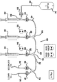
- third syringe 32 need only be operated by third syringe pump 16 (see Figure 1 ) in a single direction (i.e., the push direction, to push fluid residing within third syringe 32 into third syringe outlet 50).
- third syringe pump 16 could still operate in both directions in order to pull the plunger while first subvalve 86 of fourth valve 24 was opened in order to allow fluid to pass from the catheter into fluid subsystem 58.
- syringe 32 could be used to pull fluid including blood or other fluid from the catheter.
- controller 114 could, alternatively, only provide a power source for drug delivery devices 10, 140, 142, and 144, while a processor within each of the drug delivery devices could provide the operational control for each device.
- drug delivery devices 10, 140, 142 and 144 can form a network with one another and processor 116 while controller 114 serves as a power source.
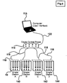
- Figure 7 shows a block diagram of an embodiment of multiple drug delivery devices 10, 140, 142 and 144 where the drug delivery devices are all connected to a network feeding back to processor 116. As shown in Figure 7 , drug delivery devices 10, 140, 142, and 144 are networked together by a plurality of wires 150.
- each syringe conserves the fluid in the syringes until the syringes are activated. Moreover, each syringe can be automatically refillable from independent reservoirs of drug solution, when connected to those reservoirs.
- the fluid reservoirs and syringes are connected together into a single fluid subsystem, by means of sterile, disposable plastic tubing, tee connectors and y-connectors. Accordingly, fluid remains in the syringes, sterile tubing and fluid reservoirs and does not exit the fluid subsystem or contaminate other components, such as the valves that control the flow of fluid. Further, the syringes, sterile tubing and sterile reservoirs are immediately accessible by the user and can be replaced with ease.
- the fluid subsystem is connected to a catheter attached to an animal, including, but not limited to, a catheter implanted into a blood vessel. It will be appreciated by one skilled in the art that this fluid subsystem can be connected to any type of catheter, including catheters not used in blood vessels. For example, the fluid subsystem can be connected to a tube implanted into the stomach or duodenum of an animal.
- Each syringe can be used to deliver fluids to or collect fluids from an animal.
- Each syringe pump is reversible (i.e. can be used to pull as well as push).
- these embodiments of the present invention can take samples by pulling a syringe to extract fluid past the last valve, into one of the syringes and, subsequently, by pushing the syringe to force the extracted fluid out the waste outlet for collection.
- Switching among the contents of the syringes is achieved by the position of valves associated with each syringe. The position of the valves either allow the fluid to be delivered to or collected from the catheter by a syringe or allows a syringe to be bypassed by the collected or delivered fluid.
- these embodiments of the present invention can be programmed to deliver a desired volume of fluid from one or multiple syringes into a single catheter without that fluid being exposed to any component which is not part of either the disposable tubing, tee connectors, y-connectors or syringes that comprise the fluid subsystem.
- These embodiments of the present invention also provide for a mechanism for flushing fluid through the fourth valve either to the catheter or to the waste outlet in order to reduce the total volume of fluid flowing to the catheter after a syringe change has been initiated.
- one syringe can be dedicated to providing a periodic flush and to ensure that the catheter is kept filled with a sterile solution, such as saline, to prevent the catheter from becoming occluded by other fluids, such as clotted blood, when used in connection with a catheter implanted in a blood vessel of the animal.
- a sterile solution such as saline
Description
- This invention relates to a device for delivery of fluids to animals, in particular a device for drug delivery thereto.
- A syringe pump is a device which typically uses an electromechanical drive to advance and/or retract the plunger on a syringe mounted to that device. Syringe pumps perform multiple tasks in medical care and in biomedical research. Syringe pumps represent the most precise and reproducible means of delivering small volumes of fluid into the body or body tissues of animals. A catheter is a hollow, flexible tube, typically made from a biocompatible plastic, that can be inserted into a vein or artery in the body. For example in humans, the insertion procedure can take place quickly and with minimal discomfort if the vein is close to the skin and readily accessible. When the vein is close to the skin, a sharp needle is inserted into the vein and the catheter is inserted through the lumen (interior) of the needle until it exits the needle tip and enters the vein. The needle is then withdrawn, leaving the catheter tip positioned within the vein. The catheter is then secured to the skin to keep it in position.
- After insertion, a catheter can be attached to a syringe and/or syringe pump, so that fluid can be delivered through it, or blood withdrawn from it. Examples of the types of fluids delivered to the body, for humans or various other animals, include physiological solutions such as saline (0.9% sodium chloride), Ringer's Solution, Ringer's Lactate Solution, or artificial cerebrospinal fluid. Such solutions can be administered alone, as in cases of dehydration or detoxification, or with supplements, including nutrients such as glucose, or therapeutic drugs intended to be delivered by parenteral administration (i.e. by the intravenous route). The administering and withdrawal of fluids from an animal can be controlled by the use of valves, or other like means for stopping or allowing fluid flow through the catheter. An example of a system that utilizes pinch valves, a syringe, a syringe pump and a catheter to withdraw blood and infuse saline is the Culex Automated Blood Sampling System manufactured by Bioanalytical Systems, Inc. of West Lafayette, Indiana US and disclosed in
U.S. Patent No. 6,062,224 . - It is not atypical, especially during biomedical research with laboratory animals, to administer more than one type of fluid. The methods for making a change in solution include: (1) removing the syringe from the syringe pump and replacing it with another syringe filled with the new fluid; (2) removing, rinsing and refilling the syringe with the new solution; (3) inserting another catheter into another blood vessel and attaching another syringe pump to that blood vessel; or (4) attaching two syringe drives to some type of mechanism which allows the user to switch to the output between these drives. In example (4), the mechanism is often a two-way or three-way valve that is actuated by hand, by electric motor, or by a mechanical or electromechanical fluid switch device. Such mechanisms require that the fluid from both syringes pass into and through the device itself, exposing the fluid to the device and exposing the device to the fluid. Such exposure means that the device must be: (1) discarded after use; or (2) thoroughly cleaned between uses to avoid contamination leftover from prior experiments. Depending on the type of materials used in the switching device, it may not be possible to easily sterilize it between uses since not all materials are thermally stable, or resistant to the effects of sterilizing gases, radiation, or cold-sterilant fluids. Thus, it is desired to provide a device for delivery of solutions to animals that does not use a mechanism that exposes the switching device to the solution. Further, it is desired to provide a device for delivery of solutions that does not require manual operation or intervention.
- In pharmaceutical research, with laboratory animals, new drugs in solution can be introduced into the body via a catheter into the bloodstream. This approach provides a means of controlling how much of the drug enters the body because the concentration of drug (e.g. milligrams per milliliter) in the solution will be known and the volume of drug delivered (e.g. milliliters) will be known. When a drug is administered by mouth, it is necessary to perform multiple tests to learn how much of that drug eventually enters the blood stream since there are several factors affecting absorption of the drug through the barrier represented by the gastrointestinal tract. When a drug solution is administered via a catheter, it can be described as a bolus dose, which is a relatively small volume of fluid administered over a relatively short period of time. In the rat, an example of a bolus dose would typically be a volume on the order of less than 3.0 milliliters and a time of less than 5 minutes. When a drug is administered as a bolus dose, its residence time in the body is determined by the rate at which the body can either metabolize it (e.g. via the liver) or excrete it (e.g. via the kidney or bile duct).
- Another approach commonly followed is to administer a continuous infusion dose. In this scenario, the volume of fluid administered can be considerably larger, but the rate of flow is usually lower (e.g. less than 10 microliters per minute), and the length of the experiment can extend for several hours or days. When a drug is administered as a continuous dose, its residence time in the body reaches a steady state in which the rate of drug input (determined by flow rate of the syringe pump) is offset by the rate of drug metabolism and excretion.
- These methods of delivering drugs to animals have several shortcomings. In many instances, a technician is required to manually introduce the drug into a solution for administration to the animal. Manual operation requires that the technician be present at all times that the drug(s) is(are) to be delivered. For a continuous infusion dose, constant attention by the technician is required to make certain that there is sufficient fluid remaining in the syringe or that the syringe is refilled without delay. Such use of human resources is expensive. Further, the accuracy of drug dose delivery is affected by the technician's skill and experience. Thus, accuracy may be compromised. Also, if more than one drug is to be administered, more than one technician may be required. These issues are further complicated by the need to change a solution and the shortcomings thereof as discussed herein. Therefore, it is desired to provide a device for drug delivery that does not require manual operation, is capable of delivery of more than one drug, does not contaminate the solution by requiring the solution to come into contact with a switching device that was exposed to another solution during a prior delivery, and permits for control of the amount and rate of flow of introduction of the drug(s) to the animal.
- The need to deliver drugs for pharmaceutical testing purposes extends both to laboratory animals (such as mice, rats, guinea pigs, gerbils, monkeys, and pigs), as well, as humans. Thus, it is desirable that the device be useable for all "animals", where the term "animals" encompasses any mammals (including humans), reptiles, amphibians, or any other animal used for laboratory testing.
- There also is a need to deliver fluids to animals other than through a catheter placed in a blood vessel. For example, a catheter or tube may be implanted into the stomach or duodenum of the animal. Thus, it is desired to provide a device for drug delivery to an animal that works in combination with all types of "catheters." As used herein, "catheter" refers to any type of tube connection to an animal's blood vessels and/or any type of tube connection that provides fluid (with or without a drug or drugs therein) to or extracts fluid from any part of the body, body tissues, organs, or blood system of the animal.
- For purposes of understanding the effect of a drug on a subject, it is desirable to extract blood samples from an animal that has received the drug. Such samples are useful for a myriad of purposes, including, ascertaining the level of drug present in the blood stream of the animal at any time relative to the original introduction of that drug. Of course, it is also possible that extraction of other body fluids may be desired, such as in determining the level of drug in the bile, or the kidney, or the aqueous humor of the eye, or fluids in the lung, for example. In addition, there are other techniques for taking biological samples based on the use of dialysis probes that involve exchange of molecules but not fluids. Therefore, it is desired to provide a device for drug delivery to animals that works in conjunction with other equipment intended to extract fluid or dialyze molecules from the animal.
-
US 6102897 describes a microvalve for disposable use in analytical chemistry or medical technology. One application example for the microvalves from the area of medical technology is described as being a programmable infusion medication application apparatus designed for outpatient and ward treatment. The core of this application apparatus is a disposable cartridge connected via a programmable, electronic control current supply apparatus. It is explained that by opening the microvalves according to an individually preselected program by the electronic control current supply apparatus, the desired infusions and medication can be fully automatically dispensed to the patient. -
US 3949746 describes a hypodermic syringe apparatus that includes a contact member having an apertured front plate and a hydraulic cylinder reciprocated mounting plate that supports a group of hypodermic needles in slidable registry with the front plate openings, which pierce a liquid absorbent web backing the front plate. Each needle is connected by a flexible tube to an adjustable stroke piston pump where inlets are connected to liquid injectable holding receptacles. -
US 4563175 describes a multiple syringe pump, comprising a pump housing, two or more seating recesses therein to receive two or more syringes for delivering two or more different substances to a patient intravenously, and a corresponding plurality of drive mechanisms in said pump housing powered by an electrical source for connection to each of the two or more syringes seated in said pump housing to move the syringe plungers at a controlled rate in the direction to discharge the contents of the syringe cylinder. The discharge ports of the syringes are connected to respective discharge tubes which in turn lead to a Y-connector which has its common outlet port connected to a single tube leading to a patient for intravenous infusion of the respective substances. -
US 6062224 , as mentioned above, describes a movement-responsive system for conducting tests on freely-moving animals. This system includes a container for housing the animal, a mechanism for rotating the container in response to rotational movement of the animal, and one or more test leads connected to the animal for performance of biomedical tests. - The claimed invention provides a drug delivery device for animals.
- The device comprises at least a first syringe coupled with a first tube connector and a second syringe coupled with a second tube connector; a plurality of disposable tubes, including at least a first tube, a second tube, a third tub and a fourth tube; at least one catheter; a first reservoir containing a first fluid; at least one second reservoir containing a drug fluid; and a third tube connector in fluid communication with the at least one catheter. The device further comprises at least a first and second pinch valve, each pinch valve having a first position and a second position, the first position and the second position each configured to receive one of the plurality of disposable tubes therethrough and for control of fluid flowing through the plurality of disposable tubes without being in fluid communication with the fluid. The first tube passes through the first position of the first pinch valve and is configured to allow the first fluid to flow between the first reservoir and the first syringe through the first tube connector. The second tube passes through the first position of the second pinch valve and is configured to allow the drug fluid to flow between the second reservoir and the second syringe through the second tube connector. The third tube passes through the second position of the second pinch valve and is configured to allow the drug fluid to flow between the second syringe and the catheter through the third tube connector. The fourth tube passes through the second position of the first pinch valve and is configured to allow the first fluid to flow from the first syringe to the at least one catheter through the third tube connector.
- No claim is made to a method for treatment of the human or animal body by surgery or therapy.
- Exemplary embodiments of the present invention relate to a device for delivery and collection of fluids to and from animals.
- In one embodiment of the present invention, the drug delivery device comprises a housing that holds a fluid subsystem and a first syringe pump, a second syringe pump and a third syringe pump. Each of the first, second and third syringe pumps are associated with a first, second and third syringe, respectively. The syringe pumps are associated with electronic controllers that control the push and/or pull operation of the first, second, and third syringes. The syringes are of the type often used for drug delivery and may be disposable. The fluid subsystem comprises a plurality of valves and plastic disposable tubing. In this embodiment, each valve is a two-position, pinch valve with two orifices that receive tubing. The orifices may be slots that make it easy to place the tubing in the valve without dismantling the fluid subsystem. Because each valve comprises a two-position, pinch valve, each orifice of the valve essentially comprises a first and second subvalve.
- In this embodiment, each of the syringes are joined to a first, second or third fluid reservoir by a first syringe inlet, a second syringe inlet and a third syringe inlet, respectively. Each syringe inlet passes through the first subvalve of first, second and third pinch valves, respectively. Each of the first, second and third syringes are joined to each other by first, second and third syringe outlets that each pass through the second subvalve of the first, second, and third pinch valves, respectively. Further, the fluid subsystem is joined to a catheter by a catheter outlet that passes through a first subvalve of a fourth pinch valve. The fluid subsystem is also joined to a waste outlet that passes through the second subvalve of the fourth pinch valve.
- This exemplary embodiment of the present invention is able to control the path of fluid(s) flowing through the fluid subsystem by operating the first, second and third syringe pumps to push or pull the first, second, and third syringes, and by opening and closing the first and second subvalves of the first, second, third, and fourth pinch valves. The opening and closing of the subvalves determines what tubes are opened and closed to the flow of fluids and allows the drug delivery device to inject one or more fluids into an animal through a catheter without contamination. Further, the operation of the device of the present invention also allows for the collection of fluid samples from the animal through the waste outlet.
-
-
Figure 1 shows a block diagram of one exemplary embodiment of the device of the present invention; -
Figure 2 shows a block diagram of the fluid subsystem utilized in the exemplary embodiment ofFigure 1 ; -
Figure 3 shows a block diagram of another embodiment of the fluid subsystem that can be utilized in the present invention; -
Figure 4 shows a block diagram of a fluid subsystem that is described but not claimed; -
Figure 5 shows a block diagram of the exemplary embodiment ofFigure 1 used together with a movement-responsive caging system and blood sampling system; -
Figure 6 shows a block diagram of one embodiment that utilizes multiple devices of the present invention connected to a central processor; -
Figure 7 shows a block diagram of another embodiment that utilizes multiple devices of the present invention connected to a central processor; and -
Figure 8 shows tables of sample procedures using the exemplary embodiment ofFigure 1 . - Referring now to
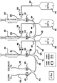
Figure 1 , there is shown a block diagram of one embodiment of the drug delivery device of the present invention. In this embodiment, adrug delivery device 10 includes ahousing 11, afirst syringe pump 12, asecond syringe pump 14, athird syringe pump 16, afirst valve 18, asecond valve 20, athird valve 22, afourth valve 24, and afluid subsystem 26. Each of the first, second, and third syringe pumps 12, 14, and 16 have associated therewith electronic controllers (not shown) disposed withinhousing 11 for controlling the operation (push and pull) of afirst syringe 28, asecond syringe 30, and athird syringe 32. It will be appreciated by one skilled in the art that the electronic controllers can be disposed withinhousing 11 and aseparate controller 114 or can be housed solely within the separate controller 114 (shown inFigure 5 ). Such syringe pumps include, for example, the Empis pumps made by Bioanalytical Systems, Inc. of West Lafayette, Indiana US. First, second, andthird syringes - In this embodiment, the electronic control circuitry (not shown) for
valves housing 11. In addition, the electronic control circuitry may reside, in whole or in part, in separate controller 114 (shown inFigure 5 ). The claimed invention requires at least a first and second pinch valve, each having a first position and a second position. In this embodiment ofFigure 1 , each of thevalves -
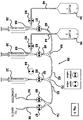
Figure 2 shows a block diagram of the fluid subsystem utilized in this exemplary embodiment. As shown inFigures 1 and2 , in this embodiment,first valve 18 comprises afirst subvalve 80 and asecond subvalve 81,second valve 20 comprises afirst subvalve 82 and asecond subvalve 83,third valve 22 comprises afirst subvalve 84 and asecond subvalve 85, andfourth valve 24 comprises afirst subvalve 86 and asecond subvalve 87. The electronic control circuitry controls the opening and closing of each of these subvalves. In operation, when the first subvalve (and hence the tube through the first subvalve) is open, the second subvalve is closed and, when the second subvalve (and hence the tube through the second subvalve) is open, the first subvalve is closed. Examples of two-position pinch valves used in the device of the present invention are the Empis Valve Assemblies made by Bioanalytical Systems, Inc. - Referring to
Figures 1 and2 ,fluid subsystem 26 includesfirst syringe 28,second syringe 30,third syringe 32,first valve 18,second valve 20,third valve 22,fourth valve 24, afirst fluid reservoir 34, asecond fluid reservoir 36, and athird fluid reservoir 38.First reservoir 34 is connected tofirst syringe 28 by afirst syringe inlet 40 that passes throughfirst subvalve 80 ofvalve 18.First syringe inlet 40 andsyringe 28 are joined together by afirst tee connector 66.Syringe 28 is connected to the rest of thefluid subsystem 26 by afirst syringe outlet 42 that passes throughsecond subvalve 81 ofvalve 18.Syringe outlet 42 andsyringe 28 are also joined together byfirst tee connector 66. Further,syringe outlet 42 is connected to the rest offluid subsystem 26 by a first y-connector 64. -
Fluid reservoir 36 is connected tosecond syringe 30 by asecond syringe inlet 44 that passes throughfirst subvalve 82 ofvalve 20.Second syringe inlet 44 andsyringe 30 are joined together by asecond tee connector 68.Syringe 30 is connected to the rest offluid subsystem 26 by asecond syringe outlet 46 that passes throughsecond subvalve 83 ofvalve 20.Second syringe outlet 46 andsyringe 30 are also joined together bysecond tee connector 68. Further,syringe outlet 46 is connected to the rest offluid subsystem 26 by first y-connector 64. -
Fluid reservoir 38 is connected tothird syringe 32 by athird syringe inlet 48 that passes throughfirst subvalve 84 ofvalve 22.Third syringe inlet 48 andsyringe 32 are joined together by athird tee connector 72.Syringe 32 is connected to the rest offluid subsystem 26 by athird syringe outlet 50 that passes through thesecond subvalve 85 ofvalve 22.Third syringe outlet 50 andsyringe 32 are also joined together bythird tee connector 72. Further,third syringe outlet 50 is connected to the rest offluid subsystem 26 by a second y-connector 70. Second y-connector 70 is connected to first y-connector 64 by a connectingtube 62. Y-connector 70 is also connected to a third y-connector 74 by asystem outlet 52. Third y-connector 74 connectssystem outlet 52 to acatheter outlet 54 that passes throughfirst subvalve 86 ofvalve 24 and to awaste outlet 56 that passes throughsecond subvalve 87 ofvalve 24. - Each of the tee connectors and y-connectors have three receiving positions that can receive one of the tubes described above or one of the first, second and third syringes. While the tee connectors and y-connectors are shown as different structures in
Figures 1-4 , it will be appreciated by one skilled in the art that the tee connectors and y-connectors can be the same structure. Further, it will be appreciated by one skilled in the art that any type of connector can be used with the present invention, so long as the connectors in this embodiment have three receiving positions that can receive one of the tubes described above or one of the first, second and third syringes. Moreover, while the terms "inlet" and "outlet" are used herein to describe the tubing offluid subsystem 26, such terms are not intended to be limiting as to the direction of fluid therethrough. Specifically, each "inlet" tube and each "outlet" tube supports bidirectional flow of fluid therethrough. - First, second, and third syringe pumps 12, 14, and 16 (see
Figure 1 ) are operable to push or pull first, second, andthird syringes subvalves drug delivery device 10 will be able to control the path of fluid(s) flowing throughfluid subsystem 26 by controlling the subvalves and the syringes. To better understand the fluid subsystem of the device of the present invention, block diagrams of alternate exemplary embodiments of the fluid subsystem are shown inFigures 2 and3 .Figure 4 shows a block diagram of a fluid subsystem that is described but not claimed. - For example, in
Figure 2 ,first subvalve 80 offirst valve 18,first subvalve 82 ofsecond valve 20, andfirst subvalve 84 ofthird valve 22 are all shown in the open position. If the plungers in first, second andthird syringes reservoirs syringe inlets syringes syringes second subvalve 81 offirst valve 18,second subvalve 83 ofsecond valve 20, andsecond subvalve 85 ofthird valve 22 were all open, then first subvalves 80, 82, and 84 would be closed. If this were the case, any action bysyringe second subvalve syringes - In
Figure 2 ,second subvalve 87 offourth valve 24 is shown open, whilefirst subvalve 86 offourth valve 24 is closed. If any combination ofsecond subvalves syringes syringe outlet second subvalve 87 offourth valve 24 to waste. If, inFigure 2 ,first subvalve 86 offourth valve 24 was open, then second subvalve 87 offourth valve 24 would be closed. If any combination ofsecond subvalves syringes syringe outlet first subvalve 86 offourth valve 24 to the catheter. Likewise, if any combination offirst subvalves syringes first subvalve 86 offourth valve 24 toline 52 and possibly throughsyringe outlets -
Figure 3 shows another exemplary embodiment of a fluid subsystem that can be utilized in the subject invention. As shown inFigure 3 , this embodiment comprises afluid subsystem 58 that has the same components of the previous embodiment except for thirdfluid reservoir 38 and third syringe inlet 48 (shown inFigure 2 ) are not present. In this embodiment, third tee connector 72 (shown inFigure 2 ) is not needed andthird syringe outlet 50 is connected directly tothird syringe 32. Hence,third syringe 32 cannot be refilled in this embodiment. Thus,third syringe 32 need only be operated by third syringe pump 16 (seeFigure 1 ) in a single direction (i.e., the push direction, to push fluid residing withinthird syringe 32 into third syringe outlet 50). Alternatively,third syringe pump 16 could still operate in both directions in order to pull the plunger whilefirst subvalve 86 offourth valve 24 was opened in order to allow fluid to pass from the catheter intofluid subsystem 58. Thus,syringe 32 could be used to pull fluid including blood or other fluid from the catheter. This embodiment may be useful in the event the particular solution ofthird syringe 32 is only needed in limited quantities, or when testing the catheter to make sure that it is not occluded by a blood clot or other biological obstacle. It is also useful in cases when there is a limitation on the amount of available drug and there is not sufficient material available to prepare a bag of solution as influid reservoir -
Figure 4 shows an embodiment of a fluid subsystem that is described but not claimed. This embodiment comprisesfluid subsystem 60 and differs from the other embodiments because it only has one fluid reservoir, namely,first fluid reservoir 34. Thus, this embodiment does not have secondfluid reservoir 36,third fluid reservoir 38,second syringe inlet 44, andthird syringe inlet 48. Further, second andthird tee connectors second syringe outlet 46 connectssecond syringe 30 directly to first y-connector 64 andthird syringe outlet 50 connectsthird syringe 32 directly to y-connector 70. - In the embodiment of
Figure 4 , second andthird syringes Figure 1 ) in a single direction (i.e., the push direction in order to push fluid residing withinsecond syringe 30 intosecond syringe outlet 46 and to push fluid residing withinthird syringe 32 into third syringe outlet 50). This embodiment may be useful in the event the particular solutions of second andthird syringes syringes second syringe 30 andthird syringe 32 to cause fluid to be drawn intosecond syringe outlet 46 andthird syringe outlet 50 in order to collect a sample through the catheter from the animal. - The alternate embodiments of the fluid subsystem illustrate the flexibility of the fluid subsystem of the device of the present invention. While only three embodiments are shown and described, it will be appreciated by one skilled in the art that many other versions are possible. The scope of the invention is defined by the claims.
- Another embodiment that is described but not claimed comprises a fluid system that has no fluid reservoirs connected to any of first, second and
third syringes syringes - Referring now to
Figure 5 , there is shown a block diagram of the device of the present invention connected to a movement-responsive caging system and to a blood sampling system. The movement-responsive caging system is of the type disclosed inU.S. Patent No. 5,816,256 , and the blood sampling system of the type disclosed inU.S. Patent No. 6,062,224 . As shown inFigure 5 ,housing 11 ofdrug delivery device 10 is connected to asterile saline reservoir 112.Sterile saline reservoir 112 is comparable tofirst fluid reservoir 34 shown inFigures 1-4 . The movement-responsive caging system comprises acage 100 having arat 102 therein, and acontroller 104. The blood sampling system includes ablood sampling controller 106, asterile saline reservoir 108, and afraction collector 110. - Referring still to
Figure 5 , this exemplary embodiment also includes aprocessor 116 and asyringe controller 114. In this embodiment,syringe controller 114 contains the electrical power and control systems for control of the syringe pumps and the valves housed withinhousing 11. This arrangement differs from that ofFigure 1 in that the electronic control resides outside ofhousing 11.Housing 11 is electrically connected tosyringe controller 114 by asyringe control line 118.Syringe controller 114 is also electrically connected tocontroller 104 of the movement-responsive caging system by afirst line 120 and toprocessor 116 by asecond line 122. The electrical connection betweensyringe controller 114 andcontroller 104 of the movement-responsive caging system is for the purpose of providing an alternate route for recording animal activity signals, including rotation, duration of rotation, rearing, and duration of rearing, when the test system comprises only the drug infusion device and the interactive caging system. Furthermore,syringe controller 114 is electrically connected tocontroller 106 of the blood sampling system by athird line 124. In this manner, communication is possible between the device of the present invention, the movement-responsive caging system, and the blood sampling system. - In this embodiment,
processor 116 provides a user interface for the device of the present invention and the blood sampling system.Processor 116 may comprise a personal computer, for example, having the Windows™ operating system and user interface program operating thereon. In addition to being connected bysecond line 122 tosyringe controller 114,processor 116 is also electrically connected by afifth line 128 tocontroller 106 of the blood sampling system. The electrical connection betweencontroller 106 of the blood sampling system andprocessor 116 is for the purpose of sending instructions from the user interface software onprocessor 116 to an operational processor incontroller 106, and for
recording operational messages fromcontroller 106 on the storage media ofprocessor 116.Controller 106 is also connected tofraction collector 110 by afourth line 126. It will be appreciated by one skilled in the art that lines 118, 120, 122, 124, 126 and 128 can comprise any type of electrical connections including, but not limited to, serial connection, parallel connection, use of a bus, ethernet, internet, Appletalk or other network, radio frequency, microwave, or Internet. The salient feature of each operative connection between these devices is that it is able to transmit and/or receive the data appropriate to the device at a speed sufficient for operational use of the device and in a manner that does not interfere with other devices in proximity to that device. - The use of the device of the present invention with a movement-responsive caging system and blood sampling system permits for the sampling of blood of a freely moving animal (within the cage) while administering drug(s) to the animal. For example, in a typical experiment, the animal would be allowed to acclimate to the environment of the caging system for some period of time. During this time, a sample of blood would be taken to establish that no drug was present in the system prior to administration by
drug delivery device 10. During this time, the animal activity would be monitored byprocessor 116 to establish a pre-dose pattern of activity. Then,drug delivery device 10 would be activated to deliver a predetermined volume of fluid from one or more syringes to the animal, and this would also trigger blood sampling to occur at predetermined intervals. Animal activity would be continuously recorded byprocessor 116 to monitor post-dose activity. - Referring now to
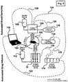
Figure 6 , there is shown a block diagram of one embodiment of multipledrug delivery devices central processor 116. In this embodiment and the embodiment ofFigure 7 ,processor 116 comprises a computer. Further, in this embodiment,drug delivery devices syringe controller 114 by syringe control lines 118. Further,controller 114 is electrically connected byline 122 toprocessor 116. In this embodiment, all fourdrug delivery devices controller 114. While this exemplary embodiment of the present invention utilizes four drug delivery devices, it will be appreciated by one skilled in the art that any number of the drug delivery devices can be used. - It will also be appreciated by one skilled in the art that
controller 114 could, alternatively, only provide a power source fordrug delivery devices drug delivery devices processor 116 whilecontroller 114 serves as a power source.Figure 7 shows a block diagram of an embodiment of multipledrug delivery devices processor 116. As shown inFigure 7 ,drug delivery devices wires 150. Further,drug delivery devices processor 116 so that each drug delivery device in the network feeds back toprocessor 116. In this arrangement, the power supply would be isolated from possible damage by fluid leaks or spillage fromdrug delivery devices devices processor 116.Figures 6 and7 are further illustrative of the flexibility of the device of the present invention. Multiple experiments or drug deliveries may be operated simultaneously and independently using these drug delivery devices. For example, the experimental protocol carried out ondevice 10 would not have to resemble the protocol carried out on any of theother devices - In two separate tables,
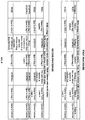
Figure 8 outlines two sample procedures using the exemplary embodiment of the drug delivery device ofFigure 1 andFigure 2 . In the first procedure ofFigure 8 , a procedure is illustrated for checking a catheter and flushing the catheter with sterile saline. To illustrate one method to accomplish this objective, reference is made to the embodiment ofFigure 1 andFigure 2 . First syringe reservoir 34 (seeFigure 1 ) is filled with saline solution.Second syringe reservoir 36 andthird syringe reservoir 38 are either empty or full. The catheter connected tocatheter outlet 54 is implanted in a blood vessel, such as the jugular or femoral vein, of the animal. - To begin,
first valve 18 is set to the position that opens subvalve 80 and allows fluid to pass throughfirst syringe inlet 40.Second valve 20 is set to the position that opens subvalve 82 and allows fluid to pass throughsecond syringe inlet 44.Third valve 22 is set to the position that opens subvalve 85 and allows fluid to pass throughthird syringe outlet 50.Fourth valve 24 is set to the position that opens subvalve 86 and allows fluid to pass throughcatheter outlet 54.First syringe 28 is pulled byfirst syringe pump 12,second syringe 30 is left stationary, andthird syringe 32 is pulled bythird syringe pump 16 until blood appears incatheter outlet 54. In this manner,first syringe 28 is filled with saline, whilecatheter outlet 54 is partially filled with blood to indicate that the catheter is not occluded by a clot, other biological obstacle, or kink in the catheter. - After
first syringe 28 andthird syringe 32 are pulled,first valve 18 is set to the position that opens subvalve 81 and allows fluid to pass throughfirst syringe outlet 42.Third valve 22 is set to the position that openssubvalve 84.Second valve 20 remains open tosecond syringe inlet 44 andfourth valve 24 remains open tocatheter outlet 54. Second andthird syringes first syringe pump 12. In this manner, saline fromsyringe 28 is pushed throughfluid subsystem 26 until it pushes blood out ofcatheter outlet 54 and back down the catheter. The catheter is now flushed and ready for introduction of one or more drugs. - In the second procedure of
Figure 8 , a procedure is illustrated for flushing a catheter with sterile saline, refilling the second syringe, injecting fluid from the second syringe, and flushing with saline. This procedure outlines the sequence of events used to deliver a bolus injection of a drug. The procedure could be repeated with increasing concentrations of the drug as needed. To illustrate one method to accomplish this objective, reference is made to the exemplary embodiment ofFigure 1 andFigure 2 . - After the steps described above in association with the first procedure of checking a catheter and flushing the catheter with sterile saline,
valve 18 is set to the position wheresubvalve 80 is open and allows fluid to pass throughfirst syringe inlet 40.Valve 20 is set to the position that opens subvalve 82 and allows fluid to pass throughsecond syringe inlet 44.Valve 22 is set to the position that opens subvalve 84 and allows fluid to pass throughthird syringe inlet 48.Valve 24 is set to the position that opens subvalve 86 and allows fluid to pass throughcatheter outlet 54. Whilethird syringe 32 remains stationary,second syringe 30 is pulled bysecond syringe pump 14 until it fills with the fluid fromsecond fluid reservoir 36 andfirst syringe 28 is pulled byfirst syringe pump 12 until it fills with saline fromfirst fluid reservoir 34. - Next,
valves valve 20 is set to the position that opens subvalve 83 and allows fluid to pass throughsecond syringe outlet 46. While first and third syringes remain stationary,second syringe 30 is then pushed until the total volume of the fluid is delivered. Fluid fromreservoir 36 will normally comprise a drug that is desired to be tested. After the drug is delivered,valve 18 is set to the position wheresubvalve 81 is open and allows fluid to pass throughfirst syringe outlet 42 andvalve 20 is set to the position wheresubvalve 82 is open and allows fluid to pass throughsecond syringe inlet 44. While second andthird syringes first syringe 28 is pushed byfirst syringe pump 12. In this manner, saline fromsyringe 28 is pushed throughfluid subsystem 26 until the total volume of saline is delivered. In this manner,drug delivery device 10 flushes thefluid subsystem 26 and the catheter. The catheter is now flushed and ready for introduction of one or more other drugs. As will be appreciated by those of skill in the art, there are additional procedures that could be achieved by the device of the present invention. Other examples include situations such as delivery of a bolus injection (loading dose) followed by continuous delivery of a drug from a refillable syringe (continuous infusion). - This procedure enables the drug delivery device to flush saline, or another like fluid, down the catheter to keep the catheter from becoming occluded by other fluids, such as clotted blood. The volume of saline and the interval for this flushing can be preprogrammed. The flushing will occur as described above in association with
Figures 1 and2 , but will also keepsubvalve 81 ofvalve 18 closed momentarily while syringe pump 12 begins to pushsyringe 28. In this way,drug delivery device 10 begins to build up pressure. Oncesubvalve 81 is open and allows fluid to pass throughfirst syringe outlet 42 the pressure behind the flushing saline will blow out any clots forming in the catheter. - As stated above, no claim is made to a method for treatment of the human or animal body by surgery or therapy.
- It will be appreciated by those of skill in the art that these embodiments of the device of the present invention meet the specific needs of drug delivery, because they utilize multiple disposable syringes that can be easily replaced with clean and sterile syringes. Further, each syringe is independently programmable, with start, stop, direction and flow rate independent of the others, so that one syringe may run while the other syringe(s) is(are) stopped, or two syringes may run while the other syringe(s) is(are) stopped, or all syringes may run together, or none may run, during any programmed sequence. The independent control for each of these syringes conserves the fluid in the syringes until the syringes are activated. Moreover, each syringe can be automatically refillable from independent reservoirs of drug solution, when connected to those reservoirs.
- The fluid reservoirs and syringes are connected together into a single fluid subsystem, by means of sterile, disposable plastic tubing, tee connectors and y-connectors. Accordingly, fluid remains in the syringes, sterile tubing and fluid reservoirs and does not exit the fluid subsystem or contaminate other components, such as the valves that control the flow of fluid. Further, the syringes, sterile tubing and sterile reservoirs are immediately accessible by the user and can be replaced with ease. The fluid subsystem is connected to a catheter attached to an animal, including, but not limited to, a catheter implanted into a blood vessel. It will be appreciated by one skilled in the art that this fluid subsystem can be connected to any type of catheter, including catheters not used in blood vessels. For example, the fluid subsystem can be connected to a tube implanted into the stomach or duodenum of an animal.
- Each syringe can be used to deliver fluids to or collect fluids from an animal. Each syringe pump is reversible (i.e. can be used to pull as well as push). Thus, these embodiments of the present invention can take samples by pulling a syringe to extract fluid past the last valve, into one of the syringes and, subsequently, by pushing the syringe to force the extracted fluid out the waste outlet for collection. Switching among the contents of the syringes is achieved by the position of valves associated with each syringe. The position of the valves either allow the fluid to be delivered to or collected from the catheter by a syringe or allows a syringe to be bypassed by the collected or delivered fluid.
- Thus, these embodiments of the present invention can be programmed to deliver a desired volume of fluid from one or multiple syringes into a single catheter without that fluid being exposed to any component which is not part of either the disposable tubing, tee connectors, y-connectors or syringes that comprise the fluid subsystem. These embodiments of the present invention also provide for a mechanism for flushing fluid through the fourth valve either to the catheter or to the waste outlet in order to reduce the total volume of fluid flowing to the catheter after a syringe change has been initiated. In one embodiment, one syringe can be dedicated to providing a periodic flush and to ensure that the catheter is kept filled with a sterile solution, such as saline, to prevent the catheter from becoming occluded by other fluids, such as clotted blood, when used in connection with a catheter implanted in a blood vessel of the animal.
- While the present invention has been described in considerable detail with references to particular embodiments thereof, such is offered by way of non-limiting examples of the invention as many other versions are possible. The scope of the invention is defined by the claims.
Claims (15)
- A drug delivery device (10) for animals, the device comprising:at least a first syringe (28) coupled with a first tube connector (66) and a second syringe (30) coupled with a second tube connector (68);a plurality of disposable tubes, including at least a first tube (40), a second tube (44), a third tube (46) and a fourth tube (42);at least one catheter;a first reservoir (34) containing a first fluid;at least one second reservoir (36) containing a drug fluid;a third tube connector (64) in fluid communication with the at least one catheter;characterized in that the device further comprises:at least a first and second pinch valve (18 and 20), each pinch valve having a first position and a second position, the first position and the second position each configured to receive one of the plurality of disposable tubes therethrough and for control of fluid flowing through the plurality of disposable tubes without being in fluid communication with the fluid;wherein the first tube passes through the first position of the first pinch valve and is configured to allow the first fluid to flow between the first reservoir and the first syringe through the first tube connector (66);wherein the second tube passes through the first position of the second pinch valve and is configured to allow the drug fluid to flow between the second reservoir and the second syringe through the second tube connector (68); andwherein the third tube passes through the second position of the second pinch valve and is configured to allow the drug fluid to flow between the second syringe and the catheter through the third tube connector, andwherein the fourth tube passes through the second position of the first pinch valve and is configured to allow the first fluid to flow from the first syringe to the at least one catheter through the third tube connector.
- The drug delivery device of claim 1, further comprising a first and second syringe pump (12 and 14), wherein the first syringe pump is associated with the first syringe and the second syringe pump is associated with the second syringe such that the first and second syringe pumps operate each of the first and second syringes independently of each other.
- The drug delivery device of claim 2, further comprising a third syringe (32).
- The drug delivery device of claim 3, further comprising a third syringe pump (16) operably connected to the third syringe.
- The drug delivery device of claim 4, further comprising a third reservoir (38).
- The drug delivery device of claim 5, further comprising a fourth tube connector (72) in fluid communication with the third reservoir and the third syringe, a fifth tube connector (70) in fluid communication with the at least one catheter and the third syringe and a third pinch valve (22), wherein a fifth tube (48) passes through the first position of the third pinch valve and is configured to allow fluid to flow from the third reservoir to the third syringe through the fourth tube connector, and wherein a sixth tube (50) passes through the second position of the third pinch valve and is configured to allow fluid to flow from the third syringe to the at least one catheter through the fifth tube connector.
- The drug delivery device of claim 6, wherein the plurality of disposable tubes further comprises a system outlet (52) that connects the fifth tube connector to the at least one catheter.
- The drug delivery device of claim 7, wherein the at least one catheter comprises a catheter connected to the system outlet (52) by a catheter outlet (54).
- The drug delivery device of claim 8, further comprising a fourth pinch valve (24) with its first position containing the catheter outlet.
- The drug delivery device of claim 9, further comprising a waste outlet (56) that is connected to the system outlet (52) and that is contained by the second position of the fourth pinch valve (24), so that when the first position of the fourth pinch valve is open, the second position of the fourth pinch valve is closed and fluid is allowed to pass between the system outlet and the catheter outlet (54), and when the second position of the fourth pinch valve is open, the first position of the fourth valve is closed and fluid is allowed to pass between the system outlet and the waste outlet.
- The drug delivery device of claim 10, further comprising a controller (114) that is operably connected to the first, second, and third syringe pumps (12, 14, 16) and is operably connected to the first, second, third, and fourth pinch valves (18, 20, 22, 24), such that the controller automatically controls the movement of the first, second, and third syringe pumps and controls the movement of the first and second positions of each of the first, second, third, and fourth pinch valves.
- The drug delivery device of claim 4, wherein the first reservoir (34) contains a drug.
- The drug delivery device of claim 4, wherein the first reservoir (34) contains a saline solution.
- The drug delivery device of claim 1, the device further comprising: at least one waste outlet (56) connected to each of the at least one syringes (34, 36, 38) by the at least one disposable tubes; and wherein the at least one catheter is connected to each of the at least one syringes by the at least one disposable tube and catheter outlet (54); and wherein there are at least two valves (18, 20, 22, 24), a first valve and a second valve, wherein the first valve has a first position that receives the at least one syringe outlet therethrough and has a second position that receives one of the at least one disposable tubes therethrough, and wherein the second valve has a first position that receives the catheter outlet therethrough and has a second position that receives the waste outlet therethrough.
- The drug delivery device of claim 11, wherein the controller is capable of operating at least the first and second syringes and at least the first and second pinch valves to flush a fluid through the plurality of disposable tubes.
Applications Claiming Priority (3)
| Application Number | Priority Date | Filing Date | Title |
|---|---|---|---|
| US39381602P | 2002-07-03 | 2002-07-03 | |
| US393816P | 2002-07-03 | ||
| PCT/US2003/021398 WO2004004802A2 (en) | 2002-07-03 | 2003-07-03 | Device and method for drug delivery to animals |
Publications (3)
| Publication Number | Publication Date |
|---|---|
| EP1539273A2 EP1539273A2 (en) | 2005-06-15 |
| EP1539273A4 EP1539273A4 (en) | 2006-09-06 |
| EP1539273B1 true EP1539273B1 (en) | 2018-10-10 |
Family
ID=30115650
Family Applications (1)
| Application Number | Title | Priority Date | Filing Date |
|---|---|---|---|
| EP03763376.5A Expired - Lifetime EP1539273B1 (en) | 2002-07-03 | 2003-07-03 | Device for drug delivery to animals |
Country Status (8)
| Country | Link |
|---|---|
| US (3) | US7488309B2 (en) |
| EP (1) | EP1539273B1 (en) |
| AU (1) | AU2003247942A1 (en) |
| CA (1) | CA2491297C (en) |
| ES (1) | ES2694473T3 (en) |
| HU (1) | HUE040600T2 (en) |
| TR (1) | TR201816259T4 (en) |
| WO (1) | WO2004004802A2 (en) |
Families Citing this family (32)
| Publication number | Priority date | Publication date | Assignee | Title |
|---|---|---|---|---|
| US7488309B2 (en) * | 2002-07-03 | 2009-02-10 | Bioanalytical Systems, Inc. | Device and method for drug delivery to animals |
| US7163031B2 (en) | 2004-06-15 | 2007-01-16 | Mallinckrodt Inc. | Automated dispensing system and associated method of use |
| WO2006029270A1 (en) * | 2004-09-07 | 2006-03-16 | Smith & Nephew, Inc. | Methods and devices for sterile field transfer |
| DE102005022428A1 (en) | 2005-05-14 | 2006-11-16 | B. Braun Medizinelektronik Gmbh & Co. Kg | Method for controlling several infusion pumps in an array for administering substances at specified rates to a living being utilizes algrithms ensuring automatic activation and deactivation of the pumps |
| ITMI20051826A1 (en) * | 2005-09-29 | 2007-03-30 | Novachem S A | KIT FOR THE PARENTERAL ADMINISTRATION OF MEDICATIONS |
| US9259526B2 (en) | 2005-11-21 | 2016-02-16 | Acist Medical Systems, Inc. | Medical fluid injection system and method for guided setup |
| US8977517B2 (en) * | 2006-06-05 | 2015-03-10 | Creighton University | System and methods for evaluating efficacy of appetite-affecting drugs |
| US8425469B2 (en) * | 2007-04-23 | 2013-04-23 | Jacobson Technologies, Llc | Systems and methods for controlled substance delivery network |
| WO2009041826A1 (en) * | 2007-09-28 | 2009-04-02 | Robert Stephen Murphy | Infusion pump mechanism |
| US9044542B2 (en) | 2007-12-21 | 2015-06-02 | Carticept Medical, Inc. | Imaging-guided anesthesia injection systems and methods |
| EP2231230A4 (en) * | 2007-12-21 | 2013-01-23 | Carticept Medical Inc | Articular injection system |
| US8545440B2 (en) * | 2007-12-21 | 2013-10-01 | Carticept Medical, Inc. | Injection system for delivering multiple fluids within the anatomy |
| JP5328242B2 (en) * | 2008-07-04 | 2013-10-30 | キヤノン株式会社 | Cleaning device for medicine discharge device |
| US20100228232A1 (en) * | 2009-02-18 | 2010-09-09 | Loay Salman | Catheter flushing assembly |
| US8579885B2 (en) * | 2009-02-20 | 2013-11-12 | University Of Southern California | MEMS electrochemical bellows actuator |
| WO2010096651A2 (en) * | 2009-02-20 | 2010-08-26 | University Of Southern California | Drug delivery device with in-plane bandpass regulation check valve in heat-shrink packaging |
| US9222819B2 (en) | 2009-02-20 | 2015-12-29 | University Of Southern California | Tracking and controlling fluid delivery from chamber |
| US20110087166A1 (en) * | 2009-04-06 | 2011-04-14 | Mark Davis | Laboratory syringe pumps |
| WO2010144533A1 (en) * | 2009-06-09 | 2010-12-16 | Jacobson Technologies, Llc | Controlled delivery of substances system and method |
| US9114206B2 (en) * | 2010-04-22 | 2015-08-25 | Raland Technologies, Llc | Device for infusion of prescription medicines or treatments |
| ES2381509B2 (en) * | 2010-10-27 | 2013-02-20 | David Requena Polonio | AUTOMATIC SYSTEM TO ADMINISTER DRUGS TO AN ANIMAL. |
| WO2013107723A1 (en) * | 2012-01-16 | 2013-07-25 | Sanofi-Aventis Deutschland Gmbh | Blinding kit for clinical trials |
| BR112015001559A2 (en) | 2012-07-26 | 2017-07-04 | Syrinjector Ltd | method and system for mass vaccinations |
| ES2625351T1 (en) | 2014-04-24 | 2017-07-19 | Exthera Medical Corporation | Method to eliminate bacteria from the blood using high flow |
| US11357966B2 (en) | 2015-04-23 | 2022-06-14 | B. Braun Medical Inc. | Compounding device, system, kit, software, and method |
| US11911551B2 (en) | 2016-03-02 | 2024-02-27 | Exthera Medical Corporation | Method for treating drug intoxication |
| CA3085165A1 (en) * | 2016-12-08 | 2018-06-14 | Blackswan Vascular, Inc. | Devices, systems, and methods for the embolization of body lumens |
| JP7402827B2 (en) * | 2018-06-11 | 2023-12-21 | エピセントアールエックス,インコーポレイテッド | Pharmaceutical injection devices, systems and methods |
| US20200037941A1 (en) * | 2018-08-02 | 2020-02-06 | Jason Hollis | Cvc line blood drawing assembly |
| US20210077711A1 (en) * | 2019-09-16 | 2021-03-18 | Carefusion 303, Inc. | Syringe control assembly |
| EP4072613A1 (en) * | 2019-12-12 | 2022-10-19 | Stavro Medical, Inc. | Syringe-based manual extracorporeal blood treatment systems and methods employing batch processing |
| CN111134894B (en) * | 2020-01-17 | 2022-02-22 | 上海长海医院 | Sampling method for in vivo determination of continuous dynamic free drug concentration of canine prostate tissue |
Family Cites Families (37)
| Publication number | Priority date | Publication date | Assignee | Title |
|---|---|---|---|---|
| US2797149A (en) * | 1953-01-08 | 1957-06-25 | Technicon International Ltd | Methods of and apparatus for analyzing liquids containing crystalloid and non-crystalloid constituents |
| NL248506A (en) | 1958-07-11 | |||
| NL6904268A (en) | 1969-03-20 | 1970-09-22 | ||
| US3699004A (en) * | 1970-08-31 | 1972-10-17 | Technicon Instr | Method and apparatus for sample analysis on a continuous flow basis |
| US3949746A (en) | 1974-09-03 | 1976-04-13 | Animal Systems, Inc. | Animal injector apparatus |
| US4196730A (en) | 1977-08-01 | 1980-04-08 | Wilson Dennis R | Liquid drug dispenser |
| US4340153A (en) | 1980-11-28 | 1982-07-20 | Spivey David L | Method and apparatus for medication dispensing |
| US4526754A (en) * | 1982-07-30 | 1985-07-02 | Technicon Instruments Corporation | Sample transport system |
| US4512764A (en) | 1982-09-27 | 1985-04-23 | Wunsch Richard E | Manifold for controlling administration of multiple intravenous solutions and medications |
| US4559036A (en) | 1983-12-14 | 1985-12-17 | Wunsch Richard E | Apparatus for controlling administration of multiple intravenous solutions and medications |
| US4563175A (en) | 1983-12-19 | 1986-01-07 | Lafond Margaret | Multiple syringe pump |
| CA1257165A (en) | 1984-02-08 | 1989-07-11 | Paul Epstein | Infusion system having plural fluid input ports and at least one patient output port |
| US4666430A (en) | 1984-12-05 | 1987-05-19 | I-Flow Corporation | Infusion pump |
| GB8602732D0 (en) | 1986-02-04 | 1986-03-12 | Univ Brunel | Taking samples from patients |
| US4666429A (en) | 1986-02-26 | 1987-05-19 | Intelligent Medicine, Inc. | Infusion device having improved valving apparatus |
| US5048525A (en) * | 1987-01-30 | 1991-09-17 | Minnesota Mining And Manufacturing Company | Blood parameter measurement system with compliant element |
| US4777953A (en) * | 1987-02-25 | 1988-10-18 | Ash Medical Systems, Inc. | Capillary filtration and collection method for long-term monitoring of blood constituents |
| US4920056A (en) * | 1988-02-19 | 1990-04-24 | The Dow Chemical Company | Apparatus and method for automated microbatch reaction |
| US5134079A (en) * | 1989-03-27 | 1992-07-28 | International Technidyne Corp. | Fluid sample collection and delivery system and methods particularly adapted for body fluid sampling |
| US5037390A (en) * | 1989-12-28 | 1991-08-06 | Kenneth Raines | System and method for mixing parenteral nutrition solutions |
| US5723282A (en) * | 1991-07-08 | 1998-03-03 | The American National Red Cross | Method of preparing organs for vitrification |
| US5268147A (en) * | 1992-02-26 | 1993-12-07 | Miles, Inc. | Reversible direction capsule chemistry sample liquid analysis system and method |
| US5399497A (en) * | 1992-02-26 | 1995-03-21 | Miles, Inc. | Capsule chemistry sample liquid analysis system and method |
| US5248616A (en) * | 1992-06-04 | 1993-09-28 | Beckman Joseph S | Method and apparatus for detection of aqueous nitric oxide from biological samples |
| DE4336336A1 (en) * | 1992-11-23 | 1994-05-26 | Lang Volker | Cassette infusion system |
| US5411485A (en) | 1993-04-19 | 1995-05-02 | Hyprotek | Catheter access system and method |
| US5449064A (en) * | 1994-03-03 | 1995-09-12 | University Of Kansas | On-line interface and valve for capillary electophoresis system |
| DE19749011A1 (en) | 1996-11-19 | 1998-05-20 | Lang Volker | Micro=valve for one time use has opening closed by plug mounted on resistance plate |
| US6062224A (en) * | 1997-04-17 | 2000-05-16 | Bioanalytical Systems, Inc. | Movement-response system for conducting tests on freely-moving animals |
| US5911252A (en) | 1997-04-29 | 1999-06-15 | Cassel; Douglas | Automated syringe filling system for radiographic contrast agents and other injectable substances |
| US6019735A (en) * | 1997-08-28 | 2000-02-01 | Visco Technologies, Inc. | Viscosity measuring apparatus and method of use |
| US6794197B1 (en) * | 1998-07-14 | 2004-09-21 | Zyomyx, Inc. | Microdevice and method for detecting a characteristic of a fluid |
| US6150119A (en) * | 1999-01-19 | 2000-11-21 | Caliper Technologies Corp. | Optimized high-throughput analytical system |
| US6287265B1 (en) * | 1999-06-23 | 2001-09-11 | Cindy L. Gleason | Blood collection kit |
| US6736783B2 (en) * | 2000-04-12 | 2004-05-18 | Merck & Co., Inc. | Automated blood sampling apparatus |
| US6767319B2 (en) * | 2001-06-29 | 2004-07-27 | Medrad, Inc. | Delivery methods, systems and components for use with hazardous pharmaceutical substances |
| US7488309B2 (en) * | 2002-07-03 | 2009-02-10 | Bioanalytical Systems, Inc. | Device and method for drug delivery to animals |
-
2003
- 2003-07-02 US US10/612,484 patent/US7488309B2/en not_active Expired - Lifetime
- 2003-07-03 CA CA2491297A patent/CA2491297C/en not_active Expired - Lifetime
- 2003-07-03 HU HUE03763376A patent/HUE040600T2/en unknown
- 2003-07-03 TR TR2018/16259T patent/TR201816259T4/en unknown
- 2003-07-03 EP EP03763376.5A patent/EP1539273B1/en not_active Expired - Lifetime
- 2003-07-03 ES ES03763376.5T patent/ES2694473T3/en not_active Expired - Lifetime
- 2003-07-03 WO PCT/US2003/021398 patent/WO2004004802A2/en not_active Application Discontinuation
- 2003-07-03 AU AU2003247942A patent/AU2003247942A1/en not_active Abandoned
-
2008
- 2008-06-20 US US12/143,700 patent/US8622964B2/en active Active
-
2014
- 2014-01-06 US US14/148,236 patent/US9078605B2/en not_active Expired - Lifetime
Non-Patent Citations (1)
| Title |
|---|
| None * |
Also Published As
| Publication number | Publication date |
|---|---|
| US8622964B2 (en) | 2014-01-07 |
| AU2003247942A8 (en) | 2004-01-23 |
| AU2003247942A1 (en) | 2004-01-23 |
| CA2491297C (en) | 2014-12-23 |
| WO2004004802A3 (en) | 2005-02-03 |
| US20140121591A1 (en) | 2014-05-01 |
| US20040054320A1 (en) | 2004-03-18 |
| ES2694473T3 (en) | 2018-12-21 |
| TR201816259T4 (en) | 2018-11-21 |
| EP1539273A2 (en) | 2005-06-15 |
| US7488309B2 (en) | 2009-02-10 |
| HUE040600T2 (en) | 2019-03-28 |
| US9078605B2 (en) | 2015-07-14 |
| WO2004004802A2 (en) | 2004-01-15 |
| CA2491297A1 (en) | 2004-01-15 |
| US20080255500A1 (en) | 2008-10-16 |
| EP1539273A4 (en) | 2006-09-06 |
Similar Documents
| Publication | Publication Date | Title |
|---|---|---|
| EP1539273B1 (en) | Device for drug delivery to animals | |
| US4784157A (en) | Method and apparatus for taking samples from or administering medication to a patient | |
| CN109758667B (en) | Medicament device | |
| JP5276075B2 (en) | Fluid transport system, fluid transport device and method for transporting hazardous fluid | |
| EP2094336B1 (en) | Syringe for sequential expression of different liquids and method of using same | |
| DE60023352T2 (en) | INTERRUPTION FREE FLOW PUMPING DEVICE AND METHOD | |
| CA2079449C (en) | Automatic in-line reconstitution system | |
| JPH11500029A (en) | Feedback controlled drug delivery system | |
| WO2010011976A2 (en) | Medication delivery devices having penetrable sterility barriers and alignment features | |
| US20040035743A1 (en) | System, methods and apparatus for administering medical liquids | |
| US20040230182A1 (en) | Drug delivery through encapsulation | |
| CN115243741A (en) | Drug infusion device, system and method | |
| CN110234372B (en) | Apparatus and method for automatic degassing and filling of catheters | |
| JP3243103B2 (en) | Blood glucose control device | |
| JP2744911B2 (en) | Two-way catheter for implantable pump system | |
| SE525294C2 (en) | Catheter device comprising inner and outer catheters, administers active substance according to pulsed flow sequence | |
| JP6393309B2 (en) | Improved fluid sampling system | |
| CN116531605A (en) | Micro-infusion pump |
Legal Events
| Date | Code | Title | Description |
|---|---|---|---|
| PUAI | Public reference made under article 153(3) epc to a published international application that has entered the european phase |
Free format text: ORIGINAL CODE: 0009012 |
|
| 17P | Request for examination filed |
Effective date: 20050131 |
|
| AK | Designated contracting states |
Kind code of ref document: A2 Designated state(s): AT BE BG CH CY CZ DE DK EE ES FI FR GB GR HU IE IT LI LU MC NL PT RO SE SI SK TR |
|
| AX | Request for extension of the european patent |
Extension state: AL LT LV MK |
|
| DAX | Request for extension of the european patent (deleted) | ||
| A4 | Supplementary search report drawn up and despatched |
Effective date: 20060804 |
|
| 17Q | First examination report despatched |
Effective date: 20061026 |
|
| STAA | Information on the status of an ep patent application or granted ep patent |
Free format text: STATUS: EXAMINATION IS IN PROGRESS |
|
| REG | Reference to a national code |
Ref country code: DE Ref legal event code: R079 Ref document number: 60351550 Country of ref document: DE Free format text: PREVIOUS MAIN CLASS: A61M0005000000 Ipc: A61M0005140000 |
|
| GRAP | Despatch of communication of intention to grant a patent |
Free format text: ORIGINAL CODE: EPIDOSNIGR1 |
|
| STAA | Information on the status of an ep patent application or granted ep patent |
Free format text: STATUS: GRANT OF PATENT IS INTENDED |
|
| RIC1 | Information provided on ipc code assigned before grant |
Ipc: A61B 5/153 20060101ALI20180410BHEP Ipc: A61B 5/155 20000101ALI20180410BHEP Ipc: A61M 5/145 19900101ALI20180410BHEP Ipc: A61M 5/168 19900101ALI20180410BHEP Ipc: A61M 5/14 19680901AFI20180410BHEP Ipc: A61B 5/15 20000101ALI20180410BHEP |
|
| INTG | Intention to grant announced |
Effective date: 20180511 |
|
| RIN1 | Information on inventor provided before grant (corrected) |
Inventor name: KISSINGER, CANDICE, B. Inventor name: BOUGHER, JOSEPH, A. Inventor name: HAMPSCH, JAMES, M. |
|
| GRAS | Grant fee paid |
Free format text: ORIGINAL CODE: EPIDOSNIGR3 |
|
| GRAA | (expected) grant |
Free format text: ORIGINAL CODE: 0009210 |
|
| STAA | Information on the status of an ep patent application or granted ep patent |
Free format text: STATUS: THE PATENT HAS BEEN GRANTED |
|
| AK | Designated contracting states |
Kind code of ref document: B1 Designated state(s): AT BE BG CH CY CZ DE DK EE ES FI FR GB GR HU IE IT LI LU MC NL PT RO SE SI SK TR |
|
| REG | Reference to a national code |
Ref country code: GB Ref legal event code: FG4D |
|
| REG | Reference to a national code |
Ref country code: CH Ref legal event code: EP Ref country code: AT Ref legal event code: REF Ref document number: 1050492 Country of ref document: AT Kind code of ref document: T Effective date: 20181015 |
|
| REG | Reference to a national code |
Ref country code: IE Ref legal event code: FG4D |
|
| REG | Reference to a national code |
Ref country code: DE Ref legal event code: R096 Ref document number: 60351550 Country of ref document: DE |
|
| REG | Reference to a national code |
Ref country code: SE Ref legal event code: TRGR |
|
| REG | Reference to a national code |
Ref country code: ES Ref legal event code: FG2A Ref document number: 2694473 Country of ref document: ES Kind code of ref document: T3 Effective date: 20181221 |
|
| REG | Reference to a national code |
Ref country code: CH Ref legal event code: NV Representative=s name: VALIPAT S.A. GEVERS SA, CH |
|
| REG | Reference to a national code |
Ref country code: CH Ref legal event code: PK Free format text: BERICHTIGUNGEN |
|
| REG | Reference to a national code |
Ref country code: NL Ref legal event code: MP Effective date: 20181010 |
|
| RIC2 | Information provided on ipc code assigned after grant |
Ipc: A61B 5/155 20060101ALI20180410BHEP Ipc: A61M 5/168 20060101ALI20180410BHEP Ipc: A61M 5/145 20060101ALI20180410BHEP Ipc: A61B 5/153 20060101ALI20180410BHEP Ipc: A61M 5/14 20060101AFI20180410BHEP Ipc: A61B 5/15 20060101ALI20180410BHEP |
|
| REG | Reference to a national code |
Ref country code: AT Ref legal event code: MK05 Ref document number: 1050492 Country of ref document: AT Kind code of ref document: T Effective date: 20181010 |
|
| REG | Reference to a national code |
Ref country code: HU Ref legal event code: AG4A Ref document number: E040600 Country of ref document: HU |
|
| PG25 | Lapsed in a contracting state [announced via postgrant information from national office to epo] |
Ref country code: NL Free format text: LAPSE BECAUSE OF FAILURE TO SUBMIT A TRANSLATION OF THE DESCRIPTION OR TO PAY THE FEE WITHIN THE PRESCRIBED TIME-LIMIT Effective date: 20181010 |
|
| REG | Reference to a national code |
Ref country code: CH Ref legal event code: PCAR Free format text: NEW ADDRESS: RUE DES NOYERS 11, 2000 NEUCHATEL (CH) |
|
| PG25 | Lapsed in a contracting state [announced via postgrant information from national office to epo] |
Ref country code: AT Free format text: LAPSE BECAUSE OF FAILURE TO SUBMIT A TRANSLATION OF THE DESCRIPTION OR TO PAY THE FEE WITHIN THE PRESCRIBED TIME-LIMIT Effective date: 20181010 Ref country code: FI Free format text: LAPSE BECAUSE OF FAILURE TO SUBMIT A TRANSLATION OF THE DESCRIPTION OR TO PAY THE FEE WITHIN THE PRESCRIBED TIME-LIMIT Effective date: 20181010 Ref country code: BG Free format text: LAPSE BECAUSE OF FAILURE TO SUBMIT A TRANSLATION OF THE DESCRIPTION OR TO PAY THE FEE WITHIN THE PRESCRIBED TIME-LIMIT Effective date: 20190110 |
|
| PG25 | Lapsed in a contracting state [announced via postgrant information from national office to epo] |
Ref country code: GR Free format text: LAPSE BECAUSE OF FAILURE TO SUBMIT A TRANSLATION OF THE DESCRIPTION OR TO PAY THE FEE WITHIN THE PRESCRIBED TIME-LIMIT Effective date: 20190111 Ref country code: PT Free format text: LAPSE BECAUSE OF FAILURE TO SUBMIT A TRANSLATION OF THE DESCRIPTION OR TO PAY THE FEE WITHIN THE PRESCRIBED TIME-LIMIT Effective date: 20190210 |
|
| REG | Reference to a national code |
Ref country code: DE Ref legal event code: R097 Ref document number: 60351550 Country of ref document: DE |
|
| PG25 | Lapsed in a contracting state [announced via postgrant information from national office to epo] |
Ref country code: DK Free format text: LAPSE BECAUSE OF FAILURE TO SUBMIT A TRANSLATION OF THE DESCRIPTION OR TO PAY THE FEE WITHIN THE PRESCRIBED TIME-LIMIT Effective date: 20181010 Ref country code: CZ Free format text: LAPSE BECAUSE OF FAILURE TO SUBMIT A TRANSLATION OF THE DESCRIPTION OR TO PAY THE FEE WITHIN THE PRESCRIBED TIME-LIMIT Effective date: 20181010 Ref country code: IT Free format text: LAPSE BECAUSE OF FAILURE TO SUBMIT A TRANSLATION OF THE DESCRIPTION OR TO PAY THE FEE WITHIN THE PRESCRIBED TIME-LIMIT Effective date: 20181010 |
|
| PLBE | No opposition filed within time limit |
Free format text: ORIGINAL CODE: 0009261 |
|
| STAA | Information on the status of an ep patent application or granted ep patent |
Free format text: STATUS: NO OPPOSITION FILED WITHIN TIME LIMIT |
|
| PG25 | Lapsed in a contracting state [announced via postgrant information from national office to epo] |
Ref country code: RO Free format text: LAPSE BECAUSE OF FAILURE TO SUBMIT A TRANSLATION OF THE DESCRIPTION OR TO PAY THE FEE WITHIN THE PRESCRIBED TIME-LIMIT Effective date: 20181010 Ref country code: EE Free format text: LAPSE BECAUSE OF FAILURE TO SUBMIT A TRANSLATION OF THE DESCRIPTION OR TO PAY THE FEE WITHIN THE PRESCRIBED TIME-LIMIT Effective date: 20181010 Ref country code: SK Free format text: LAPSE BECAUSE OF FAILURE TO SUBMIT A TRANSLATION OF THE DESCRIPTION OR TO PAY THE FEE WITHIN THE PRESCRIBED TIME-LIMIT Effective date: 20181010 |
|
| 26N | No opposition filed |
Effective date: 20190711 |
|
| PG25 | Lapsed in a contracting state [announced via postgrant information from national office to epo] |
Ref country code: SI Free format text: LAPSE BECAUSE OF FAILURE TO SUBMIT A TRANSLATION OF THE DESCRIPTION OR TO PAY THE FEE WITHIN THE PRESCRIBED TIME-LIMIT Effective date: 20181010 |
|
| PG25 | Lapsed in a contracting state [announced via postgrant information from national office to epo] |
Ref country code: MC Free format text: LAPSE BECAUSE OF FAILURE TO SUBMIT A TRANSLATION OF THE DESCRIPTION OR TO PAY THE FEE WITHIN THE PRESCRIBED TIME-LIMIT Effective date: 20181010 |
|
| PG25 | Lapsed in a contracting state [announced via postgrant information from national office to epo] |
Ref country code: LU Free format text: LAPSE BECAUSE OF NON-PAYMENT OF DUE FEES Effective date: 20190703 |
|
| PG25 | Lapsed in a contracting state [announced via postgrant information from national office to epo] |
Ref country code: CY Free format text: LAPSE BECAUSE OF FAILURE TO SUBMIT A TRANSLATION OF THE DESCRIPTION OR TO PAY THE FEE WITHIN THE PRESCRIBED TIME-LIMIT Effective date: 20181010 |
|
| PGFP | Annual fee paid to national office [announced via postgrant information from national office to epo] |
Ref country code: TR Payment date: 20220628 Year of fee payment: 20 |
|
| PGFP | Annual fee paid to national office [announced via postgrant information from national office to epo] |
Ref country code: SE Payment date: 20220915 Year of fee payment: 20 Ref country code: IE Payment date: 20220926 Year of fee payment: 20 Ref country code: GB Payment date: 20220921 Year of fee payment: 20 Ref country code: ES Payment date: 20220928 Year of fee payment: 20 Ref country code: DE Payment date: 20220919 Year of fee payment: 20 |
|
| PGFP | Annual fee paid to national office [announced via postgrant information from national office to epo] |
Ref country code: HU Payment date: 20220709 Year of fee payment: 20 Ref country code: FR Payment date: 20220908 Year of fee payment: 20 Ref country code: BE Payment date: 20220912 Year of fee payment: 20 |
|
| PGFP | Annual fee paid to national office [announced via postgrant information from national office to epo] |
Ref country code: CH Payment date: 20220915 Year of fee payment: 20 |
|
| REG | Reference to a national code |
Ref country code: DE Ref legal event code: R071 Ref document number: 60351550 Country of ref document: DE |
|
| P01 | Opt-out of the competence of the unified patent court (upc) registered |
Effective date: 20230526 |
|
| REG | Reference to a national code |
Ref country code: CH Ref legal event code: PL |
|
| REG | Reference to a national code |
Ref country code: GB Ref legal event code: PE20 Expiry date: 20230702 Ref country code: ES Ref legal event code: FD2A Effective date: 20230726 |
|
| REG | Reference to a national code |
Ref country code: BE Ref legal event code: MK Effective date: 20230703 |
|
| REG | Reference to a national code |
Ref country code: SE Ref legal event code: EUG |
|
| REG | Reference to a national code |
Ref country code: IE Ref legal event code: MK9A |
|
| PG25 | Lapsed in a contracting state [announced via postgrant information from national office to epo] |
Ref country code: IE Free format text: LAPSE BECAUSE OF EXPIRATION OF PROTECTION Effective date: 20230703 Ref country code: GB Free format text: LAPSE BECAUSE OF EXPIRATION OF PROTECTION Effective date: 20230702 Ref country code: ES Free format text: LAPSE BECAUSE OF EXPIRATION OF PROTECTION Effective date: 20230704 |