EP1538873A2 - Hearing aid with wireless transmission system and corresponding transmission method - Google Patents
Hearing aid with wireless transmission system and corresponding transmission method Download PDFInfo
- Publication number
- EP1538873A2 EP1538873A2 EP04026930A EP04026930A EP1538873A2 EP 1538873 A2 EP1538873 A2 EP 1538873A2 EP 04026930 A EP04026930 A EP 04026930A EP 04026930 A EP04026930 A EP 04026930A EP 1538873 A2 EP1538873 A2 EP 1538873A2
- Authority
- EP
- European Patent Office
- Prior art keywords
- hearing aid
- receiving
- frequency range
- transmission
- telecoil
- Prior art date
- Legal status (The legal status is an assumption and is not a legal conclusion. Google has not performed a legal analysis and makes no representation as to the accuracy of the status listed.)
- Granted
Links
- 230000005540 biological transmission Effects 0.000 title claims abstract description 31
- 238000000034 method Methods 0.000 title description 4
- 230000003595 spectral effect Effects 0.000 claims abstract description 13
- 230000005236 sound signal Effects 0.000 claims abstract description 4
- 229910000859 α-Fe Inorganic materials 0.000 claims description 3
- 230000002457 bidirectional effect Effects 0.000 description 7
- 238000012546 transfer Methods 0.000 description 3
- 238000010586 diagram Methods 0.000 description 2
- 230000007175 bidirectional communication Effects 0.000 description 1
- 238000011161 development Methods 0.000 description 1
- 230000005672 electromagnetic field Effects 0.000 description 1
- 238000005265 energy consumption Methods 0.000 description 1
- 238000001914 filtration Methods 0.000 description 1
- 238000012074 hearing test Methods 0.000 description 1
- 230000001939 inductive effect Effects 0.000 description 1
- 230000010354 integration Effects 0.000 description 1
- 230000000638 stimulation Effects 0.000 description 1
- 238000002604 ultrasonography Methods 0.000 description 1
Images
Classifications
-
- H—ELECTRICITY
- H04—ELECTRIC COMMUNICATION TECHNIQUE
- H04R—LOUDSPEAKERS, MICROPHONES, GRAMOPHONE PICK-UPS OR LIKE ACOUSTIC ELECTROMECHANICAL TRANSDUCERS; DEAF-AID SETS; PUBLIC ADDRESS SYSTEMS
- H04R25/00—Deaf-aid sets, i.e. electro-acoustic or electro-mechanical hearing aids; Electric tinnitus maskers providing an auditory perception
- H04R25/55—Deaf-aid sets, i.e. electro-acoustic or electro-mechanical hearing aids; Electric tinnitus maskers providing an auditory perception using an external connection, either wireless or wired
- H04R25/558—Remote control, e.g. of amplification, frequency
-
- H—ELECTRICITY
- H04—ELECTRIC COMMUNICATION TECHNIQUE
- H04B—TRANSMISSION
- H04B5/00—Near-field transmission systems, e.g. inductive loop type
-
- H04B5/28—
-
- H—ELECTRICITY
- H04—ELECTRIC COMMUNICATION TECHNIQUE
- H04R—LOUDSPEAKERS, MICROPHONES, GRAMOPHONE PICK-UPS OR LIKE ACOUSTIC ELECTROMECHANICAL TRANSDUCERS; DEAF-AID SETS; PUBLIC ADDRESS SYSTEMS
- H04R25/00—Deaf-aid sets, i.e. electro-acoustic or electro-mechanical hearing aids; Electric tinnitus maskers providing an auditory perception
- H04R25/55—Deaf-aid sets, i.e. electro-acoustic or electro-mechanical hearing aids; Electric tinnitus maskers providing an auditory perception using an external connection, either wireless or wired
- H04R25/554—Deaf-aid sets, i.e. electro-acoustic or electro-mechanical hearing aids; Electric tinnitus maskers providing an auditory perception using an external connection, either wireless or wired using a wireless connection, e.g. between microphone and amplifier or using Tcoils
-
- H—ELECTRICITY
- H04—ELECTRIC COMMUNICATION TECHNIQUE
- H04R—LOUDSPEAKERS, MICROPHONES, GRAMOPHONE PICK-UPS OR LIKE ACOUSTIC ELECTROMECHANICAL TRANSDUCERS; DEAF-AID SETS; PUBLIC ADDRESS SYSTEMS
- H04R2225/00—Details of deaf aids covered by H04R25/00, not provided for in any of its subgroups
- H04R2225/51—Aspects of antennas or their circuitry in or for hearing aids
Definitions
- the present invention relates to a hearing aid with a Transmission device, which is a data transmission in a Spectral range above the audible range between the Hearing aid and an external device allows, and one electroacoustic transducer means for generating Sound signals from electrical signals and / or a telecoil device for receiving an electromagnetic Signal. Moreover, the present invention relates corresponding method for operating a hearing aid.
- the object of the present invention is therefore to propose a hearing aid, despite the limited space a bidirectional data transmission with an external device allows. Furthermore, a corresponding bidirectional Transmission methods are provided.
- a hearing aid with a transmission device which is a data transmission in a spectral range above the audible frequency range between the hearing aid and an external device allows, and an electro-acoustic transducer device for generating sound signals from electrical signals, wherein the electroacoustic transducer means as receiving and / or transmitting means for receiving or transmitting electromagnetic signals in the spectral range above of the audible frequency range to the external device and / or used by her.
- a hearing device is provided with a transmission device, the one data transfer in one Spectral range above the audible frequency range between the hearing aid and an external device, and a telecoil device serving as transmit and / or Receiving element of the transmission device for transmission and / or receiving electromagnetic signals to the external device or is inserted by it, their spectral components above the audible frequency range.
- the advantage of the mentioned hearing aids and methods lies in that for wireless transmission of data to and from a hearing aid no special, spacious antennas in the Hearing aid must be integrated. Rather, existing ones Components used for data transmission.
- a hearing aid whose electroacoustic Converter means for transmitting electromagnetic signals above the audible frequency range or audio frequency range is used, a telecoil device for receiving electromagnetic signals above the audio frequency range. It may also be advantageous be, the telecoil device for transmitting and the electro-acoustic Converter means for receiving the radio frequency signals to use. This will both when sending as also when receiving the high frequency signals already in Hearing device used existing component, so no additional Space for a special antenna is necessary.
- the electroacoustic transducer device or telecoil device can be in a resonant circuit for sending in one be integrated predetermined frequency band. By doing so leaves a relatively simple control of the transmission components to reach.
- a coil of the telephone coil device a Ferrite core have. This makes the telecoil device suitable better for the transmission of high-frequency signals.
- the Telecoil device in the hearing aid for receiving electromagnetic Signals in the audio frequency range and another Coil means for receiving electromagnetic signals above the audio frequency range. This has the advantage that the further coil device for the Radio frequency transmission optimized and made smaller can.
- a corresponding hearing aid as a block diagram shown, wherein the electroacoustic transducer for Transmission of radio frequency signals is used.
- a hearing aid from a microphone M, a digital signal processor DSP and a handset H as electroacoustic Converter.
- a transmitting device T which is a data signal digital signal processor DSP to wireless Transmission modulated and coded.
- the output signal of Transmitting unit T becomes the output signal in adder A. of the digital signal processor DSP.
- the by the high-frequency signal components generated electromagnetic Fields can be received outside the hearing aid. So For example, the transfer to a headset could be done, which a patient wears during a hearing test.
- the telephone coil L used which are present in most hearing aids anyway is.
- those in the telephone coil L received signals to a bandpass filter BP passed, the Spectral components of the signal above the audio frequency range filters out.
- the filtered-out high-frequency components become forwarded to a receiver circuit R. This extracted the corresponding data from the received signals and transmits them to the digital signal processor DSP of the hearing aid for example, to change its setting.
- the telecoil is usually used as an antenna for reception optimized for signals in the audio frequency range.
- the telecoil can be electrically connected (in the figure not shown) and optionally with a Be equipped ferrite core. In this way it is possible to integrate a bidirectional transmission system into the hearing aid without additional large components in the hearing aid housing to bring in.
- the telecoil L For bidirectional communication it may be sufficient be, no special antenna in addition to the electro-acoustic Converter H as a transmitter and the telecoil L as a receiver provided. If, however, as already indicated, the telecoil L not as a receiving antenna for high-frequency signal components can be shared, one for the high-frequency Reception optimized, small receiving antenna in the Hearing aid to be installed.
Abstract
Description
Die vorliegende Erfindung betrifft ein Hörgerät mit einer Übertragungseinrichtung, die eine Datenübertragung in einem Spektralbereich oberhalb des hörbaren Bereichs zwischen dem Hörgerät und einer externen Vorrichtung ermöglicht, und einer elektroakustischen Wandlereinrichtung zum Erzeugen von Schallsignalen aus elektrischen Signalen und/oder einer Telefonspuleneinrichtung zum Empfangen eines elektromagnetischen Signals. Darüber hinaus betrifft die vorliegende Erfindung entsprechende Verfahren zum Betreiben eines Hörgeräts.The present invention relates to a hearing aid with a Transmission device, which is a data transmission in a Spectral range above the audible range between the Hearing aid and an external device allows, and one electroacoustic transducer means for generating Sound signals from electrical signals and / or a telecoil device for receiving an electromagnetic Signal. Moreover, the present invention relates corresponding method for operating a hearing aid.
Im Hörgerätebereich gibt es zahlreiche Anwendungen für drahtlose Übertragungssysteme. Beispiele hierfür sind die drahtlose Programmierung, die Anbindung einer Fernbedienung, aber auch der Empfang von Audiodaten von externen Quellen. In der Praxis allerdings erweist sich die Integration eines solchen Systems in ein Hörgerät auf Grund der strengen Bedingungen bezüglich Platzbedarf und Energieverbrauch als sehr schwierig, so dass es nur sehr wenige technische Realisierungen gibt. Darüber hinaus erfordern Anwendungen wie etwa die Programmierung eine bidirektionale drahtlose Verbindung, deren Implementierung mit um so größeren technischen Problemen verbunden ist.In the hearing aid sector, there are numerous applications for wireless Transmission systems. Examples of this are the wireless Programming, connecting a remote control, but also the reception of audio data from external sources. In the Practice, however, proves the integration of such Systems in a hearing aid due to the severe conditions regarding space requirements and energy consumption as very difficult, so that there are very few technical implementations gives. In addition, applications such as programming require a bidirectional wireless connection whose Implementation associated with more technical problems is.
Derzeit auf dem Markt verfügbare Fernbedienungssysteme übertragen zwar Daten in das Hörgerät, der umgekehrte Weg allerdings ist nicht möglich. Dabei werden meist induktive Übertragungssysteme verwendet.Currently available remote control systems available on the market Although data in the hearing aid, the reverse way, however can not. These are mostly inductive transmission systems used.
Aus dem Dokument DE 100 48 354 A1 ist darüber hinaus eine bidirektionale Verbindung zwischen Hörgeräten bzw. zwischen Hörgerät und Fernbedienung beschrieben. Für diese bidirektionale Verbindung ist allerdings eine separate Antenne notwendig, die im Hörgerät untergebracht werden muss. Da sie einen entsprechenden Platzbedarf besitzt, ist ein universeller Hörgeräteeinsatz von bidirektionalen Datenübertragungssystemen verhindert.From the document DE 100 48 354 A1 is also a bidirectional Connection between hearing aids or between Hearing aid and remote control described. For this bidirectional Connection, however, a separate antenna is necessary which must be accommodated in the hearing aid. Since she has one has sufficient space, is a universal hearing aid use of bidirectional data transmission systems prevented.
In der Druckschrift DE 34 31 584 A1 und der Druckschrift EP 0 176 116 B1 ist jeweils ein Hörhilfegerät mit Ultraschallsteuerung beschrieben. Dabei wird zum Steuern des Hörgeräts ein Ultraschallsignal von dem Mikrofon des Hörgeräts aufgenommen und separat nach entsprechender Ausfilterung verarbeitet.In the document DE 34 31 584 A1 and the document EP 0 176 116 B1 is in each case a hearing aid with ultrasound control described. It is used to control the hearing aid an ultrasonic signal from the microphone of the hearing aid recorded and processed separately after appropriate filtering.
Die Aufgabe der vorliegenden Erfindung besteht somit darin, ein Hörgerät vorzuschlagen, das trotz geringem Raumangebot eine bidirektionale Datenübertragung mit einer externen Vorrichtung ermöglicht. Ferner soll ein entsprechendes bidirektionales Übertragungsverfahren bereitgestellt werden.The object of the present invention is therefore to to propose a hearing aid, despite the limited space a bidirectional data transmission with an external device allows. Furthermore, a corresponding bidirectional Transmission methods are provided.
Erfindungsgemäß wird diese Aufgabe gelöst durch ein Hörgerät mit einer Übertragungseinrichtung, die eine Datenübertragung in einem Spektralbereich oberhalb des hörbaren Frequenzbereichs zwischen dem Hörgerät und einer externen Vorrichtung ermöglicht, und einer elektroakustischen Wandlereinrichtung zum Erzeugen von Schallsignalen aus elektrischen Signalen, wobei die elektroakustische Wandlereinrichtung als Empfangs- und/oder Sendeeinrichtung zum Empfangen bzw. Senden von elektromagnetischen Signalen in dem Spektralbereich oberhalb des hörbaren Frequenzbereichs an die externe Vorrichtung und/oder von ihr eingesetzt ist.According to the invention this object is achieved by a hearing aid with a transmission device, which is a data transmission in a spectral range above the audible frequency range between the hearing aid and an external device allows, and an electro-acoustic transducer device for generating sound signals from electrical signals, wherein the electroacoustic transducer means as receiving and / or transmitting means for receiving or transmitting electromagnetic signals in the spectral range above of the audible frequency range to the external device and / or used by her.
Alternativ wird bereitgestellt ein Hörgerät mit einer Übertragungseinrichtung, die eine Datenübertragung in einem Spektralbereich oberhalb des hörbaren Frequenzbereichs zwischen dem Hörgerät und einer externen Vorrichtung ermöglicht, und einer Telefonspuleneinrichtung, die als Sende- und/oder Empfangselement der Übertragungseinrichtung zum Senden und/oder Empfangen von elektromagnetischen Signalen an die externe Vorrichtung oder von ihr eingesetzt ist, deren Spektralanteile oberhalb des hörbaren Frequenzbereichs liegen.Alternatively, a hearing device is provided with a transmission device, the one data transfer in one Spectral range above the audible frequency range between the hearing aid and an external device, and a telecoil device serving as transmit and / or Receiving element of the transmission device for transmission and / or receiving electromagnetic signals to the external device or is inserted by it, their spectral components above the audible frequency range.
Der Vorteil der genannten Hörgeräte und Verfahren liegt darin, dass zur drahtlosen Übertragung von Daten von und zu einem Hörgerät keine speziellen, geräumigen Antennen in das Hörgerät integriert werden müssen. Vielmehr werden vorhandene Bauteile für die Datenübertragung eingesetzt.The advantage of the mentioned hearing aids and methods lies in that for wireless transmission of data to and from a hearing aid no special, spacious antennas in the Hearing aid must be integrated. Rather, existing ones Components used for data transmission.
Vorzugsweise besitzt ein Hörgerät, dessen elektroakustische Wandlereinrichtung zum Senden elektromagnetischer Signale oberhalb des hörbaren Frequenzbereichs bzw. Audiofrequenzbereichs verwendet wird, eine Telefonspuleneinrichtung zum Empfangen elektromagnetischer Signale oberhalb des Audiofrequenzbereichs. Unter Umständen kann es aber auch vorteilhaft sein, die Telefonspuleneinrichtung zum Senden und die elektroakustische Wandlereinrichtung zum Empfangen der Hochfrequenzsignale zu verwenden. Damit wird sowohl beim Senden als auch beim Empfangen der Hochfrequenzsignale ein bereits im Hörgerät vorhandenes Bauelement verwendet, so dass kein zusätzlicher Bauraum für eine spezielle Antenne notwendig ist.Preferably, a hearing aid whose electroacoustic Converter means for transmitting electromagnetic signals above the audible frequency range or audio frequency range is used, a telecoil device for receiving electromagnetic signals above the audio frequency range. It may also be advantageous be, the telecoil device for transmitting and the electro-acoustic Converter means for receiving the radio frequency signals to use. This will both when sending as also when receiving the high frequency signals already in Hearing device used existing component, so no additional Space for a special antenna is necessary.
Die elektroakustische Wandlereinrichtung oder die Telefonspuleneinrichtung kann in einen Resonanzkreis zum Senden in einem vorgegebenen Frequenzband integriert sein. Dadurch lässt sich eine verhältnismäßig einfache Ansteuerung der Sendekomponenten erreichen.The electroacoustic transducer device or telecoil device can be in a resonant circuit for sending in one be integrated predetermined frequency band. By doing so leaves a relatively simple control of the transmission components to reach.
Ferner kann eine Spule der Telefonspuleneinrichtung einen Ferritkern aufweisen. Dadurch eignet sich die Telefonspuleneinrichtung besser zur Übertragung von Hochfrequenzsignalen.Further, a coil of the telephone coil device a Ferrite core have. This makes the telecoil device suitable better for the transmission of high-frequency signals.
Für spezielle Anwendungen kann es zweckmäßig sein, wenn die Telefonspuleneinrichtung im Hörgerät zum Empfang elektromagnetischer Signale im Audiofrequenzbereich und eine weitere Spuleneinrichtung zum Empfang elektromagnetischer Signale oberhalb des Audiofrequenzbereichs eingesetzt werden. Dies hat den Vorteil, dass die weitere Spuleneinrichtung für die Hochfrequenzübertragung optimiert und kleiner gestaltet werden kann.For special applications it may be useful if the Telecoil device in the hearing aid for receiving electromagnetic Signals in the audio frequency range and another Coil means for receiving electromagnetic signals above the audio frequency range. This has the advantage that the further coil device for the Radio frequency transmission optimized and made smaller can.
Die vorliegende Erfindung wird nun anhand der beigefügten Zeichnung näher erläutert, die ein Blockschaltbild eines erfindungsgemäßen Hörgeräts wiedergibt.The present invention will now be described with reference to the attached Drawing explained in more detail, which is a block diagram of an inventive Hearing aid.
Das nachfolgend näher beschriebene Ausführungsbeispiel stellt eine bevorzugte Ausführungsform der vorliegenden Erfindung dar.The embodiment described in more detail below a preferred embodiment of the present invention represents.
In Hörgeräten werden meist die sogenannten Hörer als elektroakustische Wandler verwendet. Sie emittieren auf Grund ihres elektromagnetischen Antriebs ein beträchtliches elektromagnetisches Streufeld. Dieses Streufeld, das abhängig von der Art der elektrischen Anregung des Hörers teilweise breitbandig bis in den Bereich etlicher Megahertz reichen kann, stellt eine stetige Störquelle dar, und muss bei der Hörgeräteentwicklung berücksichtigt werden. Der Erfindung liegt nun der Gedanke zu Grunde, dieses "störende" Streufeld konstruktiv für eine Übertragung von Daten aus dem Hörgerät heraus zu nutzen.In hearing aids usually the so-called listeners are called electroacoustic Transducer used. They emit due to their electromagnetic drive a considerable electromagnetic Stray field. This stray field, which depends on the type the electrical stimulation of the listener partially broadband can reach into the range of several megahertz places a constant source of interference, and must be in hearing aid development be taken into account. The invention is now the Thought based on this constructive "disturbing" stray field for a transfer of data from the hearing aid to use.
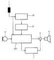
In der Figur ist ein entsprechendes Hörgerät als Blockschaltbild dargestellt, wobei der elektroakustische Wandler zum Senden von Hochfrequenzsignalen verwendet wird. Generell besteht ein Hörgerät aus einem Mikrofon M, einem digitalen Signalprozessor DSP und einem Hörer H als elektroakustischen Wandler. Im vorliegenden Beispiel wird das Ausgangssignal des digitalen Signalprozessors DSP und damit der magnetische Kreis des Hörers H mit einem entsprechend modulierten, hochfrequenten Übertragungssignal beaufschlagt. Hierzu ist in das Hörgerät eine Sendeeinrichtung T integriert, die ein Datensignal des digitalen Signalprozessors DSP zur drahtlosen Übertragung moduliert und kodiert. Das Ausgangssignal der Sendeeinheit T wird in einem Addierer A zu dem Ausgangssignal des digitalen Signalprozessors DSP summiert. Die durch die hochfrequenten Signalanteile generierten elektromagnetischen Felder können außerhalb des Hörgeräts empfangen werden. So könnte beispielsweise die Übertragung zu einem Kopfhörer erfolgen, den ein Patient bei einem Hörtest trägt.In the figure, a corresponding hearing aid as a block diagram shown, wherein the electroacoustic transducer for Transmission of radio frequency signals is used. Generally exists a hearing aid from a microphone M, a digital signal processor DSP and a handset H as electroacoustic Converter. In the present example, the output signal of the digital signal processor DSP and thus the magnetic Circle of the listener H with a correspondingly modulated, high-frequency transmission signal applied. This is in the hearing device integrates a transmitting device T, which is a data signal digital signal processor DSP to wireless Transmission modulated and coded. The output signal of Transmitting unit T becomes the output signal in adder A. of the digital signal processor DSP. The by the high-frequency signal components generated electromagnetic Fields can be received outside the hearing aid. So For example, the transfer to a headset could be done, which a patient wears during a hearing test.
Zum Empfang eines von extern übertragenen elektromagnetischen Hochfrequenzsignals kann erfindungsgemäß die Telefonspule L verwendet werden, die in den meisten Hörgeräten ohnehin vorhanden ist. Üblicherweise wird diese Telefonspule bzw. Telecoil L eingesetzt, um elektromagnetische Signale im Audiofrequenzbereich zum digitalen Signalprozessor DSP des Hörgeräts zu übertragen. Gleichzeitig werden die in der Telefonsspule L empfangenen Signale an einen Bandpassfilter BP geleitet, der Spektralanteile des Signals oberhalb des Audiofrequenzbereich ausfiltert. Die ausgefilterten hochfrequenten Anteile werden an eine Empfängerschaltung R weitergeleitet. Diese extrahiert die entsprechenden Daten aus den empfangenen Signalen und überträgt sie an den digitalen Signalprozessor DSP des Hörgeräts um beispielsweise dessen Einstellung zu ändern.For receiving an externally transmitted electromagnetic High-frequency signal according to the invention, the telephone coil L used, which are present in most hearing aids anyway is. Usually this telecoil or Telecoil L used to transmit electromagnetic signals in the audio frequency range to the digital signal processor DSP of the hearing aid transferred to. At the same time those in the telephone coil L received signals to a bandpass filter BP passed, the Spectral components of the signal above the audio frequency range filters out. The filtered-out high-frequency components become forwarded to a receiver circuit R. This extracted the corresponding data from the received signals and transmits them to the digital signal processor DSP of the hearing aid for example, to change its setting.
Die Telefonspule ist üblicherweise als Antenne für den Empfang von Signalen im Audiofrequenzbereich optimiert. Um sie nun auch an den zusätzlichen Empfang hochfrequenter Signale anzupassen, kann sie entsprechend elektrisch beschaltet (in der Figur nicht dargestellt) und gegebenenfalls mit einem Ferritkern ausgestattet sein. Auf diese Weise ist es möglich, ein bidirektionales Übertragungssystem in das Hörgerät zu integrieren, ohne zusätzlich große Bauteile in das Hörgerätegehäuse einbringen zu müssen.The telecoil is usually used as an antenna for reception optimized for signals in the audio frequency range. To her now also to the additional reception of high-frequency signals it can be electrically connected (in the figure not shown) and optionally with a Be equipped ferrite core. In this way it is possible to integrate a bidirectional transmission system into the hearing aid without additional large components in the hearing aid housing to bring in.
Für die bidirektionale Kommunikation kann es ausreichend sein, keine spezielle Antenne neben dem elektroakustischen Wandler H als Sender und der Telefonspule L als Empfänger vorzusehen. Wenn jedoch - wie bereits angedeutet - die Telefonspule L nicht als Empfangsantenne für hochfrequente Signalanteile mitbenutzt werden soll, kann eine für den hochfrequenten Empfang optimierte, kleine Empfangsantenne in das Hörgerät mit eingebaut werden.For bidirectional communication it may be sufficient be, no special antenna in addition to the electro-acoustic Converter H as a transmitter and the telecoil L as a receiver provided. If, however, as already indicated, the telecoil L not as a receiving antenna for high-frequency signal components can be shared, one for the high-frequency Reception optimized, small receiving antenna in the Hearing aid to be installed.
Claims (6)
Applications Claiming Priority (2)
| Application Number | Priority Date | Filing Date | Title |
|---|---|---|---|
| DE10356092A DE10356092B4 (en) | 2003-12-01 | 2003-12-01 | Hearing aid with wireless transmission system |
| DE10356092 | 2003-12-01 |
Publications (3)
| Publication Number | Publication Date |
|---|---|
| EP1538873A2 true EP1538873A2 (en) | 2005-06-08 |
| EP1538873A3 EP1538873A3 (en) | 2010-01-13 |
| EP1538873B1 EP1538873B1 (en) | 2015-03-18 |
Family
ID=34442383
Family Applications (1)
| Application Number | Title | Priority Date | Filing Date |
|---|---|---|---|
| EP04026930.0A Not-in-force EP1538873B1 (en) | 2003-12-01 | 2004-11-12 | Hearing aid with wireless transmission system |
Country Status (6)
| Country | Link |
|---|---|
| US (1) | US7433480B2 (en) |
| EP (1) | EP1538873B1 (en) |
| CN (1) | CN1625300B (en) |
| AU (1) | AU2004233519B2 (en) |
| DE (1) | DE10356092B4 (en) |
| DK (1) | DK1538873T3 (en) |
Cited By (1)
| Publication number | Priority date | Publication date | Assignee | Title |
|---|---|---|---|---|
| WO2019220167A1 (en) * | 2018-05-15 | 2019-11-21 | Sonova Ag | Method and apparatus for in-ear acoustic readout of data from a hearing instrument |
Families Citing this family (11)
| Publication number | Priority date | Publication date | Assignee | Title |
|---|---|---|---|---|
| DE102005016017A1 (en) * | 2005-04-07 | 2006-10-19 | Siemens Audiologische Technik Gmbh | Hearing aid device, has telephone coil utilized as antenna for high frequency signals above one mega Hertz, where evaluator is provided for evaluating high frequency signals of telephone coil |
| EP1920632B1 (en) * | 2005-06-27 | 2009-11-18 | Widex A/S | Hearing aid with enhanced high frequency reproduction and method for processing an audio signal |
| DK2002689T3 (en) * | 2006-03-16 | 2010-09-06 | Gn Resound As | A hearing aid with adaptive timing of data reception |
| DE102007046437B4 (en) * | 2007-09-28 | 2009-07-30 | Siemens Audiologische Technik Gmbh | Fully automatic switching on / off for hearing aids |
| WO2013097670A1 (en) * | 2011-12-29 | 2013-07-04 | 国民技术股份有限公司 | Method and device for information transmission |
| CN103187999A (en) * | 2011-12-29 | 2013-07-03 | 国民技术股份有限公司 | Information transmission method and device and mobile terminal |
| US20170041715A1 (en) * | 2015-07-16 | 2017-02-09 | Knowles Electronics (Beijing) Co., Ltd. | Speaker with coil antenna |
| DK3358812T3 (en) | 2017-02-03 | 2019-08-12 | Widex As | COMMUNICATION CHANNELS BETWEEN A PERSONAL COMMUNICATION ESTABLISHMENT AND AT LEAST A MAIN-BORN DEVICE |
| CN107426661A (en) * | 2017-05-03 | 2017-12-01 | 丽声助听器(福州)有限公司 | A kind of receiver for hearing aid and system |
| WO2019123286A1 (en) * | 2017-12-21 | 2019-06-27 | Cochlear Limited | Antenna for wireless communications integrated in electronic device |
| EP3525487B1 (en) | 2018-02-09 | 2020-09-16 | Widex A/S | A communication channel between a remote control and a hearing assistive device |
Citations (3)
| Publication number | Priority date | Publication date | Assignee | Title |
|---|---|---|---|---|
| DE3431584A1 (en) * | 1984-08-28 | 1986-03-13 | Siemens AG, 1000 Berlin und 8000 München | HOERHILFEGERAET |
| EP0176116A2 (en) * | 1984-09-27 | 1986-04-02 | Koninklijke Philips Electronics N.V. | Remote control system for hearing aids |
| EP0823829A2 (en) * | 1996-08-07 | 1998-02-11 | Beltone Electronics Corporation | Digital hearing aid system |
Family Cites Families (13)
| Publication number | Priority date | Publication date | Assignee | Title |
|---|---|---|---|---|
| GB1565701A (en) * | 1977-08-26 | 1980-04-23 | Wentworth Jessop J | A remote hearing aid systems |
| US4920570A (en) * | 1987-12-18 | 1990-04-24 | West Henry L | Modular assistive listening system |
| DE8816422U1 (en) * | 1988-05-06 | 1989-08-10 | Siemens Ag, 1000 Berlin Und 8000 Muenchen, De | |
| EP0480097B1 (en) * | 1990-10-12 | 1994-12-21 | Siemens Audiologische Technik GmbH | Hearing-aid with data memory |
| US5615229A (en) | 1993-07-02 | 1997-03-25 | Phonic Ear, Incorporated | Short range inductively coupled communication system employing time variant modulation |
| FI942725A (en) * | 1993-12-16 | 1995-06-17 | Pfizer | Genes encoding branched chain alpha-keto acid dehydrogenase complex from Streptomyces avermitilis |
| US5680466A (en) * | 1994-10-06 | 1997-10-21 | Zelikovitz; Joseph | Omnidirectional hearing aid |
| DE19721982C2 (en) * | 1997-05-26 | 2001-08-02 | Siemens Audiologische Technik | Communication system for users of a portable hearing aid |
| US6760457B1 (en) * | 2000-09-11 | 2004-07-06 | Micro Ear Technology, Inc. | Automatic telephone switch for hearing aid |
| DE10048354A1 (en) | 2000-09-29 | 2002-05-08 | Siemens Audiologische Technik | Method for operating a hearing aid system and hearing aid system |
| US20030045283A1 (en) * | 2001-09-06 | 2003-03-06 | Hagedoorn Johan Jan | Bluetooth enabled hearing aid |
| EP1298959A3 (en) * | 2001-09-24 | 2006-04-19 | Siemens Audiologische Technik GmbH | Hearing aid with parasitic signal control |
| DE60315819T2 (en) * | 2002-04-10 | 2008-05-15 | Sonion A/S | MICROPHONE ARRANGEMENT |
-
2003
- 2003-12-01 DE DE10356092A patent/DE10356092B4/en not_active Expired - Fee Related
-
2004
- 2004-11-12 EP EP04026930.0A patent/EP1538873B1/en not_active Not-in-force
- 2004-11-12 DK DK04026930.0T patent/DK1538873T3/en active
- 2004-11-29 AU AU2004233519A patent/AU2004233519B2/en not_active Ceased
- 2004-11-30 CN CN2004100982321A patent/CN1625300B/en not_active Expired - Fee Related
- 2004-12-01 US US11/001,966 patent/US7433480B2/en not_active Expired - Fee Related
Patent Citations (3)
| Publication number | Priority date | Publication date | Assignee | Title |
|---|---|---|---|---|
| DE3431584A1 (en) * | 1984-08-28 | 1986-03-13 | Siemens AG, 1000 Berlin und 8000 München | HOERHILFEGERAET |
| EP0176116A2 (en) * | 1984-09-27 | 1986-04-02 | Koninklijke Philips Electronics N.V. | Remote control system for hearing aids |
| EP0823829A2 (en) * | 1996-08-07 | 1998-02-11 | Beltone Electronics Corporation | Digital hearing aid system |
Cited By (2)
| Publication number | Priority date | Publication date | Assignee | Title |
|---|---|---|---|---|
| WO2019220167A1 (en) * | 2018-05-15 | 2019-11-21 | Sonova Ag | Method and apparatus for in-ear acoustic readout of data from a hearing instrument |
| US11317221B2 (en) | 2018-05-15 | 2022-04-26 | Sonova Ag | Method and apparatus for in-ear acoustic readout of data from a hearing instrument |
Also Published As
| Publication number | Publication date |
|---|---|
| DE10356092B4 (en) | 2008-04-03 |
| EP1538873B1 (en) | 2015-03-18 |
| DK1538873T3 (en) | 2015-06-29 |
| DE10356092A1 (en) | 2005-07-14 |
| AU2004233519A1 (en) | 2005-06-16 |
| US20050135645A1 (en) | 2005-06-23 |
| EP1538873A3 (en) | 2010-01-13 |
| US7433480B2 (en) | 2008-10-07 |
| AU2004233519B2 (en) | 2006-07-13 |
| CN1625300A (en) | 2005-06-08 |
| CN1625300B (en) | 2010-05-12 |
Similar Documents
| Publication | Publication Date | Title |
|---|---|---|
| DE10228157B3 (en) | Hearing aid system with a hearing aid and an external processor unit | |
| DE602004008962T2 (en) | TRANSMISSION RECEIVAL SWITCHING IN WIRELESS HEARING AID | |
| EP3451705B1 (en) | Method and apparatus for the rapid detection of own voice | |
| EP1538873B1 (en) | Hearing aid with wireless transmission system | |
| DE102008015263B4 (en) | Hearing system with subband signal exchange and corresponding method | |
| DE102007011841C5 (en) | Transmission method with dynamic transmission power adjustment and corresponding hearing aid system | |
| EP1883273A1 (en) | Control device and method for wireless transmission of audio signals when programming a hearing aid | |
| DE3115923A1 (en) | Intercom device | |
| EP1389891A2 (en) | Space saving antenna assembly for hearing aids | |
| EP1651006A2 (en) | Hearing aid with line loop to compensate the inductive disturbance fields | |
| DE102006049213A1 (en) | Hearing system with remote control as base station and corresponding communication method | |
| EP0448764B1 (en) | Programmable electrical hearing aid | |
| DE102005005603A1 (en) | Data transmission device for wireless data transmission for hearing aids and corresponding method | |
| EP2249584B1 (en) | Assembly and method for wireless data transmission between hearing aids | |
| EP2822300B1 (en) | Detection of listening situations with different signal sources | |
| DE10040660A1 (en) | Multifunction hearing aid for use with external three-dimensional sound sources has at least two receiving units and mixes received signals | |
| EP1406470B1 (en) | Wireless transmission system for hearing-aids | |
| DE10245556B3 (en) | Hearing aid or hearing aid system with a clock generator and method for their operation | |
| DE102004010868B3 (en) | Transmitting device for sending signals to a hearing aid and corresponding method and hearing aid device and method for operating a hearing aid | |
| DE102004050616B3 (en) | Combined in-the-ear and behind-the-ear hearing aid, has implantable contactless coupling unit with receive and transmit coils linking implanted unit to separate digital receiver | |
| DE2841680C3 (en) | Wireless transmission method for sound signals that works by means of ultrasound and a receiving device for carrying out the method | |
| EP2418876A1 (en) | Method for reducing interference and hearing aid | |
| DE102006059138B4 (en) | Hearing aid and / or hearing protection device with an audio input | |
| EP4243448A1 (en) | Method for operating a hearing aid | |
| EP1792414A1 (en) | Device for receiving audio signals transmitted in a wireless manner |
Legal Events
| Date | Code | Title | Description |
|---|---|---|---|
| PUAI | Public reference made under article 153(3) epc to a published international application that has entered the european phase |
Free format text: ORIGINAL CODE: 0009012 |
|
| AK | Designated contracting states |
Kind code of ref document: A2 Designated state(s): AT BE BG CH CY CZ DE DK EE ES FI FR GB GR HU IE IS IT LI LU MC NL PL PT RO SE SI SK TR |
|
| AX | Request for extension of the european patent |
Extension state: AL HR LT LV MK YU |
|
| PUAL | Search report despatched |
Free format text: ORIGINAL CODE: 0009013 |
|
| AK | Designated contracting states |
Kind code of ref document: A3 Designated state(s): AT BE BG CH CY CZ DE DK EE ES FI FR GB GR HU IE IS IT LI LU MC NL PL PT RO SE SI SK TR |
|
| AX | Request for extension of the european patent |
Extension state: AL HR LT LV MK YU |
|
| 17P | Request for examination filed |
Effective date: 20091218 |
|
| AKX | Designation fees paid |
Designated state(s): CH DE DK FR GB LI |
|
| 17Q | First examination report despatched |
Effective date: 20110509 |
|
| REG | Reference to a national code |
Ref country code: DE Ref legal event code: R079 Ref document number: 502004014855 Country of ref document: DE Free format text: PREVIOUS MAIN CLASS: H04R0025000000 Ipc: H04B0005000000 |
|
| RIC1 | Information provided on ipc code assigned before grant |
Ipc: H04R 25/00 20060101ALI20140903BHEP Ipc: H04B 5/00 20060101AFI20140903BHEP Ipc: H04B 5/06 20060101ALI20140903BHEP |
|
| GRAP | Despatch of communication of intention to grant a patent |
Free format text: ORIGINAL CODE: EPIDOSNIGR1 |
|
| INTG | Intention to grant announced |
Effective date: 20141009 |
|
| GRAS | Grant fee paid |
Free format text: ORIGINAL CODE: EPIDOSNIGR3 |
|
| GRAA | (expected) grant |
Free format text: ORIGINAL CODE: 0009210 |
|
| AK | Designated contracting states |
Kind code of ref document: B1 Designated state(s): CH DE DK FR GB LI |
|
| REG | Reference to a national code |
Ref country code: GB Ref legal event code: FG4D Free format text: NOT ENGLISH |
|
| REG | Reference to a national code |
Ref country code: CH Ref legal event code: EP Ref country code: CH Ref legal event code: NV Representative=s name: SIEMENS SCHWEIZ AG, CH |
|
| REG | Reference to a national code |
Ref country code: DE Ref legal event code: R082 Ref document number: 502004014855 Country of ref document: DE Representative=s name: FDST PATENTANWAELTE FREIER DOERR STAMMLER TSCH, DE |
|
| REG | Reference to a national code |
Ref country code: DE Ref legal event code: R096 Ref document number: 502004014855 Country of ref document: DE Effective date: 20150430 |
|
| REG | Reference to a national code |
Ref country code: DK Ref legal event code: T3 Effective date: 20150623 |
|
| REG | Reference to a national code |
Ref country code: DE Ref legal event code: R082 Ref document number: 502004014855 Country of ref document: DE Representative=s name: FDST PATENTANWAELTE FREIER DOERR STAMMLER TSCH, DE Ref country code: DE Ref legal event code: R081 Ref document number: 502004014855 Country of ref document: DE Owner name: SIVANTOS GMBH, DE Free format text: FORMER OWNER: SIEMENS AUDIOLOGISCHE TECHNIK GMBH, 91058 ERLANGEN, DE |
|
| REG | Reference to a national code |
Ref country code: FR Ref legal event code: PLFP Year of fee payment: 12 |
|
| REG | Reference to a national code |
Ref country code: DE Ref legal event code: R097 Ref document number: 502004014855 Country of ref document: DE |
|
| PLBE | No opposition filed within time limit |
Free format text: ORIGINAL CODE: 0009261 |
|
| STAA | Information on the status of an ep patent application or granted ep patent |
Free format text: STATUS: NO OPPOSITION FILED WITHIN TIME LIMIT |
|
| 26N | No opposition filed |
Effective date: 20151221 |
|
| REG | Reference to a national code |
Ref country code: FR Ref legal event code: PLFP Year of fee payment: 13 |
|
| REG | Reference to a national code |
Ref country code: FR Ref legal event code: PLFP Year of fee payment: 14 |
|
| PGFP | Annual fee paid to national office [announced via postgrant information from national office to epo] |
Ref country code: DE Payment date: 20181122 Year of fee payment: 15 Ref country code: DK Payment date: 20181126 Year of fee payment: 15 |
|
| PGFP | Annual fee paid to national office [announced via postgrant information from national office to epo] |
Ref country code: CH Payment date: 20181126 Year of fee payment: 15 Ref country code: FR Payment date: 20181127 Year of fee payment: 15 Ref country code: GB Payment date: 20181126 Year of fee payment: 15 |
|
| REG | Reference to a national code |
Ref country code: DE Ref legal event code: R119 Ref document number: 502004014855 Country of ref document: DE |
|
| REG | Reference to a national code |
Ref country code: DK Ref legal event code: EBP Effective date: 20191130 |
|
| REG | Reference to a national code |
Ref country code: CH Ref legal event code: PL |
|
| PG25 | Lapsed in a contracting state [announced via postgrant information from national office to epo] |
Ref country code: LI Free format text: LAPSE BECAUSE OF NON-PAYMENT OF DUE FEES Effective date: 20191130 Ref country code: CH Free format text: LAPSE BECAUSE OF NON-PAYMENT OF DUE FEES Effective date: 20191130 |
|
| GBPC | Gb: european patent ceased through non-payment of renewal fee |
Effective date: 20191112 |
|
| PG25 | Lapsed in a contracting state [announced via postgrant information from national office to epo] |
Ref country code: GB Free format text: LAPSE BECAUSE OF NON-PAYMENT OF DUE FEES Effective date: 20191112 Ref country code: FR Free format text: LAPSE BECAUSE OF NON-PAYMENT OF DUE FEES Effective date: 20191130 Ref country code: DE Free format text: LAPSE BECAUSE OF NON-PAYMENT OF DUE FEES Effective date: 20200603 Ref country code: DK Free format text: LAPSE BECAUSE OF NON-PAYMENT OF DUE FEES Effective date: 20191130 |