EP1538751A2 - Tuning circuit with amplitude attenuation function and integrated circuit for radio communication apparatus - Google Patents
Tuning circuit with amplitude attenuation function and integrated circuit for radio communication apparatus Download PDFInfo
- Publication number
- EP1538751A2 EP1538751A2 EP04257480A EP04257480A EP1538751A2 EP 1538751 A2 EP1538751 A2 EP 1538751A2 EP 04257480 A EP04257480 A EP 04257480A EP 04257480 A EP04257480 A EP 04257480A EP 1538751 A2 EP1538751 A2 EP 1538751A2
- Authority
- EP
- European Patent Office
- Prior art keywords
- circuit
- resistance
- voltage
- transistor
- tuning circuit
- Prior art date
- Legal status (The legal status is an assumption and is not a legal conclusion. Google has not performed a legal analysis and makes no representation as to the accuracy of the status listed.)
- Withdrawn
Links
Images


Classifications
-
- H—ELECTRICITY
- H03—ELECTRONIC CIRCUITRY
- H03J—TUNING RESONANT CIRCUITS; SELECTING RESONANT CIRCUITS
- H03J3/00—Continuous tuning
- H03J3/20—Continuous tuning of single resonant circuit by varying inductance only or capacitance only
-
- B—PERFORMING OPERATIONS; TRANSPORTING
- B60—VEHICLES IN GENERAL
- B60R—VEHICLES, VEHICLE FITTINGS, OR VEHICLE PARTS, NOT OTHERWISE PROVIDED FOR
- B60R25/00—Fittings or systems for preventing or indicating unauthorised use or theft of vehicles
- B60R25/20—Means to switch the anti-theft system on or off
- B60R25/24—Means to switch the anti-theft system on or off using electronic identifiers containing a code not memorised by the user
-
- G—PHYSICS
- G06—COMPUTING OR CALCULATING; COUNTING
- G06K—GRAPHICAL DATA READING; PRESENTATION OF DATA; RECORD CARRIERS; HANDLING RECORD CARRIERS
- G06K19/00—Record carriers for use with machines and with at least a part designed to carry digital markings
- G06K19/06—Record carriers for use with machines and with at least a part designed to carry digital markings characterised by the kind of the digital marking, e.g. shape, nature, code
- G06K19/067—Record carriers with conductive marks, printed circuits or semiconductor circuit elements, e.g. credit or identity cards also with resonating or responding marks without active components
- G06K19/07—Record carriers with conductive marks, printed circuits or semiconductor circuit elements, e.g. credit or identity cards also with resonating or responding marks without active components with integrated circuit chips
- G06K19/0723—Record carriers with conductive marks, printed circuits or semiconductor circuit elements, e.g. credit or identity cards also with resonating or responding marks without active components with integrated circuit chips the record carrier comprising an arrangement for non-contact communication, e.g. wireless communication circuits on transponder cards, non-contact smart cards or RFIDs
-
- H—ELECTRICITY
- H03—ELECTRONIC CIRCUITRY
- H03J—TUNING RESONANT CIRCUITS; SELECTING RESONANT CIRCUITS
- H03J3/00—Continuous tuning
- H03J3/02—Details
- H03J3/16—Tuning without displacement of reactive element, e.g. by varying permeability
- H03J3/18—Tuning without displacement of reactive element, e.g. by varying permeability by discharge tube or semiconductor device simulating variable reactance
-
- H—ELECTRICITY
- H03—ELECTRONIC CIRCUITRY
- H03J—TUNING RESONANT CIRCUITS; SELECTING RESONANT CIRCUITS
- H03J5/00—Discontinuous tuning; Selecting predetermined frequencies; Selecting frequency bands with or without continuous tuning in one or more of the bands, e.g. push-button tuning, turret tuner
- H03J5/24—Discontinuous tuning; Selecting predetermined frequencies; Selecting frequency bands with or without continuous tuning in one or more of the bands, e.g. push-button tuning, turret tuner with a number of separate pretuned tuning circuits or separate tuning elements selectively brought into circuit, e.g. for waveband selection or for television channel selection
- H03J5/246—Discontinuous tuning; Selecting predetermined frequencies; Selecting frequency bands with or without continuous tuning in one or more of the bands, e.g. push-button tuning, turret tuner with a number of separate pretuned tuning circuits or separate tuning elements selectively brought into circuit, e.g. for waveband selection or for television channel selection using electronic means
Definitions
- the present invention relates to a tuning circuit with an amplitude attenuation function and an integrated circuit for radio communication apparatuses.
- FIG. 16 shows a typical example of a tuning circuit and an AGC (Automatic Gain Control) circuit in, for example, ASK (Amplitude Shift Keying) communication-
- The, tuning circuit comprises an LC parallel resonance circuit where one ends of a coil (inductance) L1 and a capacitor (capacitance) C1 are connected to a reference voltage Vref.
- the AGC circuit is made up of a variable gain amplifier, a rectifier (REC), and a comparator (COMB).
- the variable gain amplifier adjusts the amplitude of an AC (alternate current) signal from the tuning circuit and outputs through its output terminal OUT- This output terminal OUT is connected to an amplifier, a detection circuit, and a waveform shaping circuit, which process the AC signal adjusted in amplitude.
- the gain for the AC (alternate current) signal of the variable gain amplifier is determined in the rectifier and comparator. Specifically, after the rectifier produces a DC signal by smoothing the amplitude of the AC signal, the comparator compares this DC signal with a reference voltage VAGC. As a result of this comparing, when the amplitude of the AC signal is excessive, the comparator feeds back its output for decreasing the gain to the amplifier. Thus, the amplitude of the AC signal, which would otherwise be excessive, is controlled to be suppressed always being maintained at a given constant level.
- Such a tuning circuit and an AGC circuit are used in, for example, the receiver of a remote control system.
- Such remote control systems have various applications such as the open and close and locking of doors of cars, houses and the like, and the start and stop of car engines.
- One aspect of the present invention is a tuning circuit having a coil and a capacitor, comprising: a resistance-adjustment circuit connected in parallel with the coil and the capacitor, the resistance-adjustment circuit changing a resistance of the tuning circuit when resonant, the resistance-adjustment circuit comprising a series circuit of a resistor and a switching element having an ON-resistance smaller than the resistance of the resistor, wherein turning on/off the switching element causes the resistance of the tuning circuit when resonant to change.
- a tuning circuit having a coil and a capacitor, comprising: a switching element connected in parallel with the coil and the capacitor, the switching element changing a resistance of the tuning circuit when resonant, wherein changing the resistance by the switching element changes the amplitude of an output signal of the tuning circuit, the tuning circuit further comprising: a circuit to render an ON-resistance constant that eliminates dependency of the ON-resistance of the switching element on a power supply voltage, which is a source of a switching voltage for the switching element, and on temperature, wherein the circuit to render an ON-resistance constant supplies the switching element with the switching voltage to eliminate the dependency on the power supply voltage and on the temperature.
- a tuning circuit having a coil and a capacitor comprises a resistance-adjustment circuit connected in parallel with the coil and the capacitor, the resistance-adjustment circuit changing a resistance of the tuning circuit when resonant, the resistance-adjustment circuit comprising a series circuit of a resistor and a switching element having an ON-resistance smaller than the resistance of the resistor, wherein turning on/off the switching element causes the resistance of the tuning circuit when resonant to change.
- the resistance of the tuning circuit is changed by the resistance-adjustment circuit, thereby changing the amplitude of an output signal of the tuning circuit.
- the sensitivity of the tuning circuit being so high as to detect the minimal input signal, the amplitude of the output signal can be suppressed so as not to be excessive. Therefore, it has a broad dynamic range.
- the transistor When, for example, a transistor is used as the switching element, the transistor varies in the ON resistance (resistance when ON) in response to the variation of the gate voltage when ON and temperature.
- the transistor when the transistor is used as a major element for resistance adjustment of the tuning circuit when resonant, it is not possible to accurately change the resistance of the tuning circuit when resonant, due to the variation of the gate voltage and temperature.
- a transistor not a transistor but a simple resistor is used as the major component in resistance adjustment of the tuning circuit when resonant.
- This switching element as an auxiliary element having a small ON resistance that does not contribute to the resistance adjustment is connected in series with the resistor.
- This series circuit is used as a resistance-adjustment circuit.
- the resistor does not need a gate voltage and is less affected by the variation of temperature.
- the resistance of the resistor determines the resistance of the tuning circuit at the time of resonance when the switching element having a small ON resistance is turned on, with the resistance of the tuning circuit being not affected by the variation of the gate voltage and temperature.
- the amplitude of the AC signal output from the tuning circuit can be attenuated without being affected by the variation of the gate voltage and temperature.
- the switching element is constituted by a transistor, and turning on/off the transistor causes the resistance of the tuning circuit when resonant to change.
- the transistor is turned on/off to change the resistance of the tuning circuit, digital control is possible.
- power consumption of the control system can be reduced.
- the circuit of the present invention is used in a battery-operated-type apparatus, power consumption can be reduced for the battery having a limited capacity.
- the tuning circuit further comprises an automatic adjustment circuit including a comparator that changes its output when the amplitude of an output signal of the tuning circuit becomes greater than a reference amplitude level for automatic adjustment; and a transistor driving digital circuit that outputs a digital drive signal to change a voltage applied to a control electrode of the transistor in response to the change in the output of the comparator.
- an automatic adjustment circuit including a comparator that changes its output when the amplitude of an output signal of the tuning circuit becomes greater than a reference amplitude level for automatic adjustment; and a transistor driving digital circuit that outputs a digital drive signal to change a voltage applied to a control electrode of the transistor in response to the change in the output of the comparator.
- the voltage-driving automatic adjustment circuit including a comparator and a transistor driving digital circuit is provided.
- power consumption can be greatly reduced.
- the circuit of the present invention is used in a battery-operated-type apparatus, power consumption can be reduced for the battery having a limited capacity.
- a tuning circuit having a coil and a capacitor comprises a switching element connected in parallel with the coil and the capacitor, the switching element changing a resistance of the tuning circuit when resonant, and changing the resistance by the switching element changes the amplitude of an output signal of the tuning circuit.
- the tuning circuit further comprises a circuit to render an ON-resistance constant that eliminates dependency of the ON-resistance of the switching element on a power supply voltage, which is a source of a switching voltage for the switching element, and on temperature, and the circuit to render an ON-resistance constant supplies the switching element with the switching voltage to eliminate the dependency on the power supply voltage and on the temperature.
- the resistance of the tuning circuit is changed by the resistance-adjustment circuit, thereby changing the amplitude of the output signal of the tuning circuit.
- the sensitivity of the tuning circuit being so high as to detect the minimal input signal, the amplitude of the output signal can be suppressed so as not to be excessive. Therefore, it has a broad dynamic range.
- the transistor is turned on/off to change the resistance of the tuning circuit, digital control is possible.
- an analog control system comprising a variable gain amplifier and a rectifier
- power consumption of the control system can be reduced because a variable gain amplifier and a rectifier are not used.
- the circuit of the present invention is used in a battery-operated-type apparatus, power consumption can be reduced for the battery having a limited capacity.
- the transistor When, for example, a transistor is used as the switching. element, the transistor varies in the ON resistance (resistance when ON) in response to the variation of the gate voltage when ON and temperature.
- the transistor when the transistor is used as a switching element for resistance adjustment of the tuning circuit when resonant, it is not possible to accurately change the resistance of the tuning circuit when resonant, due to the variation of the gate voltage and temperature.
- the present invention comprises a circuit to render an ON-resistance constant that eliminates dependency of the ON-resistance of the switching element on a power supply voltage, which is a source of a switching voltage for the switching element, and on temperature.
- a power supply voltage which is a source of a switching voltage for the switching element
- the resistance of the tuning circuit at the time of resonance is rendered constant, without being affected by the variation of the gate voltage and temperature.
- the amplitude of the AC signal output from the tuning circuit can be attenuated without being affected by the variation of the gate voltage and temperature.
- the switching element is constituted by a transistor, and turning on/off the transistor causes the resistance of the tuning circuit when resonant to change.
- the transistor is turned on/off to change the resistance of the tuning circuit, digital control is possible.
- power consumption of the control system can be reduced.
- the circuit of the present invention is used in a battery-operated-type apparatus, power consumption can be reduced for the battery having a limited capacity.
- the tuning circuit further comprises a (VDD - V T ) voltage generating circuit to generate a difference voltage of (VDD - V T ) between the power supply voltage VDD and a threshold voltage V T of the transistor; and an A/K voltage generating circuit to generate an A/K voltage corresponding to the result of dividing a predetermined constant A by a trans-conductance coefficient K, and the circuit to render an ON-resistance constant generates, as the switching voltage applied to a control electrode of the transistor as the switching element, a voltage of V T + A/K, equal to the sum of the threshold voltage V T and the A/K voltage, produced based on the voltage of (VDD - V T ) and the A/K voltage supplied so that the ON-resistance of the transistor equals the reciprocal of the predetermined constant A.
- a (VDD - V T ) voltage generating circuit to generate a difference voltage of (VDD - V T ) between the power supply voltage VDD and a threshold voltage V T of the transistor
- the tuning circuit further comprises an automatic adjustment circuit including a comparator that changes its output when the amplitude of the output signal of the tuning circuit becomes greater than a reference amplitude level for automatic adjustment; and a transistor driving digital circuit that outputs a digital drive signal to change a voltage applied to a control electrode of the transistor in response to the change in the output of the comparator.
- an automatic adjustment circuit including a comparator that changes its output when the amplitude of the output signal of the tuning circuit becomes greater than a reference amplitude level for automatic adjustment; and a transistor driving digital circuit that outputs a digital drive signal to change a voltage applied to a control electrode of the transistor in response to the change in the output of the comparator.
- the voltage-driving automatic adjustment circuit including a comparator and a transistor driving digital circuit is provided.
- power consumption can be greatly reduced.
- the circuit of the present invention is used in a battery-operated-type apparatus, power consumption can be reduced for the battery having a limited capacity.
- An integrated circuit for a radio communication apparatus comprises the switching element and the automatic adjustment circuit in the above tuning circuit.
- the resistance of the tuning circuit is changed by the resistance-adjustment circuit or the switching element, thereby changing the amplitude of an output signal of the tuning circuit.
- the amplitude of the AC signal output from the tuning circuit can be attenuated without being affected by the variation of the gate voltage and temperature.
- the voltage-driving automatic adjustment circuit is provided.
- power consumption can be greatly reduced.
- the circuit of the present invention is used in a battery-operated-type apparatus, power consumption can be reduced for the battery having a limited capacity.
- FIGS. 1A-1C are views for explaining the principle of a tuning circuit with an amplitude attenuation function according to the present embodiment.
- This tuning circuit is used in the antennas of transceivers in communication systems.
- a resistance-adjustment element R' is connected in parallel (FIG. 1C) with a coil L1 and a capacitor C1 of an LC parallel resonance circuit (FIG. 1A) constituting a tuning circuit.
- This resistance-adjustment element R' itself has a resistance, which is indicated by R' for convenience, and changes a resistance component R0 of the tuning circuit when resonant.
- the tuning circuit itself without the resistance-adjustment element R' connected has a resistance R when resonant (FIG. 1B).
- the resistance R0 of the tuning circuit with the resistance-adjustment element R' connected is expressed as the reciprocal of (1/R + 1/R').
- the change in the Q value causes the amplitude of the output signal of the tuning circuit to change in level.
- the Q value indicates the selectivity, a characteristic, of the tuning circuit.
- the resistance R0 of the tuning circuit with the resistance-adjustment element R' connected is smaller than the resistance R for without the resistance-adjustment element R'.
- the Q value decreases, and thus the amplitude of the AC signal, which would otherwise be excessive, can be controlled to be suppressed.
- a basic circuit as a fundamental design based on the above-mentioned circuit of FIG. 1 is shown in FIG. 2.
- a transistor MP0 constitutes an element corresponding to the resistance-adjustment element R' of FIG. 1.
- the transistor MP0 is a p-type channel MOSFET.
- a reference voltage Vref (e.g., 3V) is applied to one ends (on the left side of the drawing) of the coil L1 and the capacitor C1 constituting an LC parallel resonance circuit, that is a tuning circuit.
- An AC signal resonant in this LC parallel resonance circuit is output through an output terminal (the other terminal) OUT of the coil L1 and capacitor C1.
- the resistance R0 of the tuning circuit is changed.
- a digital drive method where the transistor MP0 is used as a switching element
- an analog drive method where the transistor MP0 is driven to be in between ON and OFF-
- the voltage applied to the gate of the transistor MP0 is set to discrete values between 0V (ON voltage) and 5V (OFF voltage) (e.g., 1V, 2V, 3V) one at a time.
- OFF voltage e.g., 1V, 2V, 3V
- the digital drive method where the transistor MP0 is driven as a switching element to be ON and OFF will be described. That is, the voltage applied to the gate of the transistor MP0 is either 0V (ON voltage) or 5V (OFF voltage). For example, when the transistor MP0 becomes ON, the resistance of the tuning circuit changes, and thereby the amplitude level of the AC signal from the output terminal OUT can be adjusted.
- the AGC circuit connected to the tuning circuit comprises a level shift circuit, a hysteresis comparator, and a transistor-driving digital circuit.
- analog circuits such as the variable gain amplifier and the rectifier need not be used like the conventional circuit shown in FIG. 16. Therefore, power consumption can be greatly reduced.
- the hysteresis comparator changes its output when the amplitude of the AC signal (output signal) from the tuning circuit is at or above a reference amplitude level for automatic adjustment.
- the transistor-driving digital circuit outputs a digital drive signal VAGC for changing the voltage applied to the gate of the transistor MP0.
- the level shift circuit When inputting the AC signal from the tuning circuit to the hysteresis comparator, the level shift circuit has a function to shift the DC level of the AC signal to match the DC level of the hysteresis comparator.
- the reference voltage Vref of 3V is applied to the tuning circuit, and hence, when turning on the transistor MP0 to change the resistance, the tuning circuit outputs an AC signal superposed on a DC voltage of about 3V.
- the level shift circuit shifts the DC voltage component of about 3V to a DC level sufficiently suitable for the hysteresis comparator to operate, and also produces a center voltage of the reference amplitude level for automatic adjustment that is a comparison reference of the hysteresis comparator.
- the level shift circuit is constituted by a level shift circuit including a current mirror circuit. As shown in FIG. 3, the level shift circuit comprises a level shifter and a current mirror circuit.
- the level shifter comprises a transistor (n-type channel MOSFET) MN1, a transistor (n-type channel MOSFET) MN2, a transistor (n-type channel MOSFET) MN3, and a transistor (n-type channel MOSFET) MN4.
- the AC signal from the tuning circuit is input to the gate of the transistor MN2.
- the drain and gate of the transistor MN4 are connected to make the transistor MN4 work as a diode.
- the current mirror circuit has a constant current source supplying a constant current I1 and a transistor (n-type channel MOSFET) MN5.
- the constant current I1 supplied by the constant current source plays a major part in producing the reference voltage (reference amplitude level for automatic adjustment) applied to the inverting input terminal of the hysteresis comparator.
- the drain and gate of the transistor MN5 are connected to each other and to the gate of the transistor MN3-
- the gate of the transistor MN3 is connected to the gate of the transistor MN1 of the level shifter and the drain of the transistor MN3 is connected to the source of the transistor MN4.
- the transistors MN2 and MN4 are matched and set such that the DC voltages at the sources of them are equal.
- a DC level lower by gate-to-source voltage VGS of the transistors MN2 and MN4 than 3V is produced at the sources of the transistors MN2 and MN4.
- the source of the transistors MN2 is connected to the non-inverting input terminal (+) of the hysteresis comparator, and in contrast, the source of the transistors MN4 is connected to the inverting input terminal (-) of the hysteresis comparator.
- the same DC voltage of (3V - VGS) is applied to the non-inverting and inverting input terminals of the hysteresis comparator. That is, only the DC voltage is applied to the inverting input terminal of the hysteresis comparator.
- the hysteresis comparator has hysteresis with this DC voltage, the reference voltage (reference amplitude level for automatic adjustment), as the center.
- the signal produced by shifting the DC level of the AC signal from the tuning circuit to (3V - VGS) is applied to the non-inverting input terminal of the hysteresis comparator. That is, the hysteresis comparator compares the amplitude of the level-shifted AC signal with the reference voltage and, as the amplitude of the AC signal becomes greater than the reference voltage, changes its output from "L” to "H". The output of the hysteresis comparator is input to the transistor-driving digital circuit.
- the transistor-driving digital circuit in response to the change in the output of the hysteresis comparator, outputs a digital driving signal for changing the voltage applied to the gate of the transistors MP0.
- the transistor-driving digital circuit is a voltage-driving circuit and comprises a D flip-flop FD2 with a reset, an RSFF circuit (set reset flip-flop) made up of two NORs NR1, NR2, and a NAND ND1.
- the output of the hysteresis comparator is applied to the clock terminal C of D flip-flop FD2.
- the data terminal D and output terminal Q of D flip-flop FD2 are connected to a power supply VDD and one input terminal (reset terminal) of NOR NR1 respectively.
- a reset terminal RESET is connected to the reset terminal RN of D flip-flop FD2 and to one input terminal of NAND ND1 as well-
- the other input terminal of NAND ND1 is connected to power supply VDD and the output terminal of NAND ND1 is connected to one input terminal (set terminal) of NOR NR2 of the RSFF circuit.
- alternative means having a function of inverter can be used.
- the RSFF circuit is configured to have the two NORs NR1, NR2 as well known.
- NOR NR1 outputs the digital drive signal VAGC.
- a D flip-flop with a reset may be used as the RSFF circuit.
- the transistor-driving digital circuit is in a reset state where the level-shifted AC signal from the tuning circuit is not input to the hysteresis comparator.
- the states of the signals during this period are as follows.
- the output of the hysteresis comparator (indicated by C in FIGS. 3, 4), the output of D flip-flop FD2 (indicated by Q in FIGS. 3, 4), and the output of NAND ND1 (waveform marked as "output of NAND ND1" in FIG. 4) are at a "L” level.
- the output of NOR NR1 digital drive signal VAGC, indicated by VAGC in FIGS. 3, 4) and the voltage applied to reset terminal RESET are at an "E" level.
- the level-shifted AC signal from the tuning circuit is input to the hysteresis comparator.
- the hysteresis comparator changes its output C from "L” to "H” because the input level to the non-inverting input terminal is greater than the reference voltage to the inverting input terminal.
- a reset pulse signal is applied to reset terminal RESET (at time T2).
- output Q of D flip-flop FD2 returns to the "L” level.
- NAND ND1 outputs a "H” pulse signal in response to the reset pulse signal.
- the RSFF circuit is set and digital drive signal VAGC is inverted to be at the "H” level.
- the transistor MP0 becomes OFF, thereby stopping the above AGC operation for the tuning circuit.
- a D flip-flop with a reset may be used instead of the RSFF circuit of FIG. 3 so that its output works in the same way as the VAGC.
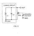
- FIGS. 5, 6 A modified example of the embodiment described with reference to FIGS. 1 to 4 is shown in FIGS. 5, 6 and the modified part will be described below. That is, 1 as shown in FIG. 5, the resistance-adjustment element R' of FIG. 1 is constituted by a transistor MN0 that is an n-type channel MOSFET. One ends (on the left side of the drawing) of the coil L1 and the capacitor C1 constituting an LC parallel resonance circuit, a tuning circuit, are connected to ground (GND). An AC signal resonant in this LC parallel resonance circuit is output through an output terminal (the other terminal) OUT of the coil L1 and capacitor C1.
- GND ground
- the level shifter of the level shift circuit comprises a transistor (p-type channel MOSFET) MP1, a transistor (p-type channel MOSFET) MP2, a transistor (p-type channel MOSFET) MP3, and a transistor (p-type channel MOSFET) MP4.
- the current mirror circuit thereof has a constant current source supplying a constant current I1 and a transistor (p-type channel MOSFET) MP5- The drain and gate of the transistor MP5 are connected to each other and to the gates of the transistors MP1, MP3.
- the transistors MP2 and MP4 are matched and set such that the DC voltages at the sources of them are equal.
- a DC level higher by gate-to-source voltage VGS of the transistors MP2 and MP4 than GND is produced at the sources of the transistors MP2 and MP4
- connection relationship in the RSFF circuit outputting digital drive signal VAGC is different from the case of FIG. 3.
- the RSFF circuit is configured and internally connected as well known. That is, in FIG. 6, one input terminal of NOR NR2 of the RSFF circuit is connected to the output of an inverter INV and one input terminal of NOR NR1 of the RSFF circuit is connected to the output terminal Q of D flip-flop FD2. Hence, when the output Q of D flip-flop FD2 is at "H", the RSFF circuit is set and thereby outputs digital drive signal VAGC of the "H" level.
- the voltage (drive signal VAGC) applied to the gate of the transistor MP0 or MN0 is set to a plurality of values such as 1V, 2V, and 3V one at a time-
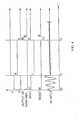
- a plurality of (herein, three) hysteresis comparators CMP1, CMP2, CMP3 and respective RS flip-flops RSFF1, RSFF2, RSFF3 each form a stage and those stages are connected in parallel as shown in FIG. 7.
- the output terminals of these RS flip-flops RSFF1 to RSFF3 are connected to a decoder, which outputs drive signal VAGC.
- a reference voltage Vref1 is input to the inverting input terminal of hysteresis comparator CMP1 to generate drive signal VAGC.
- a reference voltage Vref2 is input to the inverting input terminal of hysteresis comparator CMP2 to generate drive signal VAGC of 2V in level.
- a reference voltage vref3 is input to the inverting input terminal of hysteresis comparator CMP3 to generate drive signal VAGC of 1V in level.
- the output of the above level shift circuit is applied to the non-inverting input terminals of hysteresis comparators CMP1 to CMP3, which output results of comparing it with the respective reference voltages Vref1 to Vref3.
- RS flip-flops RSFF1 to RSFF3 output three-bit data (four values: HHH, HHL, HLL, and LLL) to the decoder.
- This decoder generates drive signal VAGC of 1V, 2V, or 3V that is selected depending on the three-bit data and outputs to transistor MP0 or MN0.
- a D flip-flop with a reset may be used as the RSFF circuit of FIG. 6 as well so that its output works in the same way as the VAGC.
- a transistor (switching element) MN0 constituted by an n-type channel MOSFET varies in ON resistance (resistance when ON) in response to the variation of the gate voltage when ON and temperature. That is, transistor MN0 cannot accurately change the resistance R0 at the time of resonance of the tuning circuit due to the variation of the gate voltage and temperature.
- resistance R0 against temperature of FIG. 8A in the case of the basic circuit indicated by an alternate long and short dashed line, resistance R0 increases and is not constant as temperature rises in the range of -50°C to 100°C. Furthermore, as shown in the characteristic graph of resistance R0 against power supply voltage VDD applied to the gate of the transistor of FIG. 8B, in the case of the basic circuit indicated by an alternate long and short dashed line, resistance R0 decreases and is not constant as power supply voltage VDD rises in the range of 1.5V to 3.5V.
- a resistance-adjustment circuit for changing the resistance of a tuning circuit when resonant is connected in parallel with the coil L1 and the capacitor C1.
- This resistance-adjustment circuit includes a series circuit of a resistor R1 and a transistor (switching element) MN0.
- This transistor MN0 is constituted by an n-type channel MOSFET having smaller resistance than that of resistor R1.
- transistor MN0 By turning on and off transistor MN0, the resistance of the tuning circuit when resonant is changed.
- the gate of transistor MN0 is held at ground level (GND) to be in an OFF state.
- transistor MN0 When transistor MN0 is ON, since being smaller than the resistance of resistor R1, its ON resistance contributes little to the resistance when resonant of the tuning circuit. Thus, the influence of the variation in the ON resistance in response to the variation of the gate voltage and temperature on the resistance when resonant of the tuning circuit can be eliminated or reduced to a negligible degree.
- resistance R0 is maintained constant as temperature changes in the range of -50°C to 100°C.
- resistance R0 against power supply voltage VDD applied to the gate of the transistor of FIG. 8B in the case of the Example 1 indicated by a solid line, resistance R0 is maintained constant as power supply voltage VDD changes in the range of 1.5V to 3.5V.
- the waveform of the AC signal output from the tuning circuit is large in amplitude before AGC operates to attenuate, as shown in the left side of FIG. 10B.
- the degree of attenuation varies according to the variation in the gate voltage (1.5V, 2.5V, 3.5V) and is not constant as shown in the center.
- the attenuated amplitude of the AC signal is constant even if the gate voltage varies.
- a switching element as a resistance-adjustment element for changing the resistance of a tuning circuit when resonant is connected in parallel with the coil L1 and the capacitor C1.
- This switching element is constituted by a transistor MN0 that is an n-type channel MOSFET.
- a circuit to render the ON-resistance constant is provided for eliminating the dependency of transistor MN0's ON-resistance on power supply voltage VDD, which is a source of a switching voltage, and on the temperature.
- This circuit to render the ON-resistance constant supplies the gate of transistor MN0 with an applied voltage Vo not subject to the variation of power supply voltage VDD and the temperature.
- the ON-resistance (drain-to-source resistance) R' of transistor MN0 is expressed as 1/K(V go - V T ), where K is its trans-conductance coefficient, V go is the gate-to-source voltage (gate voltage or switching voltage), and V T is the threshold voltage.
- K is its trans-conductance coefficient
- V go is the gate-to-source voltage (gate voltage or switching voltage)
- V T is the threshold voltage.
- VDD power supply voltage
- the circuit diagram of FIG. 11 differs from the circuit diagram of FIG. 6 in that the inverter INV and RSFF circuit are removed and that the output signal from the terminal QN of D flip-flop FD2 is used as digital drive signal VAGC.
- the (VDD - V T ) voltage generating circuit is a circuit to generate a difference voltage of VDD and V T
- the A/K voltage generating circuit is a circuit to generate a voltage corresponding to A/K (hereinafter, called A/K voltage).
- the gate of transistor MN0 to which gate voltage Vo is applied is connected to the drain of transistor MN1, the source of transistor MP6 and to the drain of transistor MP7.
- the A/K voltage from the A/K voltage generating circuit is applied to the gate of transistor MP6 and the drain thereof is connected to ground.
- the (VDD - V T ) voltage from the (VDD - V T ) voltage generating circuit is applied to the gate of transistor MP7 and the source thereof is connected to power supply VDD.
- the (VDD - V T ) voltage generating circuit applies a voltage Vo1 that is the voltage, of (VDD - V T ) to the gate of transistor MP7, and the A/K voltage generating circuit applies a voltage vo2 that is the A/K voltage to the gate of transistor MP6.
- the resistance of the tuning circuit when resonant is rendered constant without being affected by the variation in power supply voltage VDD and temperature.
- the amplitude of the AC signal output from the tuning circuit can be attenuated without being affected by the variation in power supply voltage VDD and temperature.
- FIG. 12 A specific example of the (VDD - V T ) voltage generating circuit is the circuit shown in FIG. 12.
- a circuit wherein transistors MP1, MP2 constituted by p-type channel MOSFETs and transistors MN1, MN2, MN3 constituted by n-type channel MOSFETs are combined and connected is connected to a constant current circuit, which is connected at one end to ground and causes the flow of a constant current I BIAS .
- Transistors MP1, MN1, MN3 have their gate and source connected to function as a diode.
- the drains of transistors MP1, MP2 and the gate of transistor MN2 are supplied with power supply VDD potential.
- a drain-to-source current 11 flows through transistor MP1
- a drain-to-source current 12 flows through transistor MP2-
- the voltage Vol is obtained at the gate of transistor MN3.
- This voltage Vol is the voltage of (VDD - V T ) applied to the gate of transistor MP7 in FIG. 11.
- Vo1 VDD - V T - Vo1
- V T equals about 0.7V (constant).
- I BIAS is constant
- V X is a constant.
- VDD being a variable
- VDD - 3V T - 2V X + Vo1 is not equal to zero.
- Vo1 VDD - V T .
- a specific example of the A/K voltage generating circuit is the circuit shown in FIG. 13.
- This A/K voltage generating circuit has a configuration wherein transistors MN1 to MN6 constituted by n-type channel MOSFETs and two constant current circuits connected at one ends to power supply VDD are connected as shown in the Figure, and generates voltage Vo2.
- This voltage Vo2 is the A/K voltage applied to the gate of transistor MP6 of FIG. 11.
- the constant currents supplied from the constant current circuits are indicated by I n and I n + I ctr1 , respectively. All transistors are made to operate in the saturation region.
- V cn is a constant voltage.
- V go3 V go4 + V cn
- I n + I ctrl K' (V gs1 - V T ) 2 + K' (V go4 + V cn - V T ) 2 .
- the transistor-driving digital circuit is in a reset state where the level-shifted AC signal from the tuning circuit is not input to the hysteresis comparator, during which the states of the signals are as follows.
- the output of the hysteresis comparator (indicated by C in FIGS. 11, 14), the gate voltage Vo of transistor MN0 are at a "L" level.
- the output of D flip-flop FD2 (indicated by QN (VAGC) in FIGS.
- the level-shifted AC signal from the tuning circuit is input to the hysteresis comparator.
- the hysteresis comparator changes its output C from "L” to "H” because the input level to the non-inverting input terminal is greater than the reference voltage to the inverting input terminal.
- output QN digital drive signal VAGC
- D flip-flop FD2 becomes inverted, i.e., the "L" level.
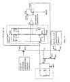
- the present invention is applied to a wireless door lock (or engine start/stop) remote control system (bidirectional communication keyless entry system) for a key 100 and a car 200.
- Key 100 comprises a receive antenna section 110, an RF (Radio Frequency) IC (Integrated Circuit) 120, a microcomputer 130, and a transmit antenna section 140 including an LC oscillation circuit.
- Receive antenna section 110 is the tuning circuit having the coil L1 and the capacitor C1 of FIG. 3, 6, 9, or 11 of the invention.
- RFIC 120 comprises the AGC circuit including transistor MP0 or MN0 of FIG. 3 or 6 of the invention.
- RFIC 120 further comprises, as well known, an amplifier AMP for amplifying the AC signal from the AGC, a detection circuit DET, a comparator COMP, and a flip-flop FF.
- the microcomputer 130 processes the output signal of this flip-flop FF and performs ASK transmission or FSK (Frequency Shift Keying) transmission via data output terminal DATAOUT and transmit antenna section 140.
- car 200 includes a receive antenna section 210, a RFIC 220, a microcomputer 230, and a transmit antenna section 240, which are configured similarly to receive antenna section 110, RFIC 120, microcomputer 130, and transmit antenna section 140 of key 100 respectively and perform processing of communication with the key 100 side.
Landscapes
- Engineering & Computer Science (AREA)
- Mechanical Engineering (AREA)
- Computer Networks & Wireless Communication (AREA)
- Computer Hardware Design (AREA)
- Microelectronics & Electronic Packaging (AREA)
- Physics & Mathematics (AREA)
- General Physics & Mathematics (AREA)
- Theoretical Computer Science (AREA)
- Amplifiers (AREA)
- Networks Using Active Elements (AREA)
- Electronic Switches (AREA)
- Control Of Amplification And Gain Control (AREA)
Abstract


Description
Claims (9)
- A tuning circuit having a coil and a capacitor, comprising:wherein turning on/off the switching element causes the resistance of the tuning circuit when resonant to change.a resistance-adjustment circuit connected in parallel with the coil and the capacitor, the resistance-adjustment circuit changing a resistance of the tuning circuit when resonant, the resistance-adjustment circuit comprising a series circuit of a resistor and a switching element having an ON-resistance smaller than the resistance of the resistor,
- The tuning circuit according to claim 1, wherein the switching element is constituted by a transistor, and turning on/off the transistor causes the resistance of the tuning circuit when resonant to change.
- The tuning circuit according to claim 2, further comprising an automatic adjustment circuit,
the automatic adjustment circuit comprising:a comparator that changes its output when the amplitude of an output signal of the tuning circuit becomes greater than a reference amplitude level for automatic adjustment; anda transistor driving digital circuit that outputs a digital drive signal to change a voltage applied to a control electrode of the transistor in response to the change in the output of the comparator. - An integrated circuit for a radio communication apparatus comprising:the resistance-adjustment circuit and the automatic adjustment circuit in the tuning circuit according to claim 3.
- A tuning circuit having a coil and a capacitor, comprising:wherein changing the resistance by the switching element changes the amplitude of an output signal of the tuning circuit,a switching element connected in parallel with the coil and the capacitor, the switching element changing a resistance of the tuning circuit when resonant,
the tuning circuit further comprising:wherein the circuit to render an ON-resistance constant supplies the switching element with the switching voltage to eliminate the dependency on the power supply voltage and on the temperature.a circuit to render an ON-resistance constant that eliminates dependency of the ON-resistance of the switching element on a power supply voltage, which is a source of a switching voltage for the switching element, and on temperature, - The tuning circuit according to claim 5, wherein the switching element is constituted by a transistor, and turning on/off the transistor causes the resistance of the tuning circuit when resonant to change.
- The tuning circuit according to claim 6, further comprising:wherein the circuit to render an ON-resistance constant generates, as the switching voltage applied to a control electrode of the transistor as the switching element, a voltage of VT + A/K, equal to the sum of the threshold voltage VT and the A/K voltage, produced based on the voltage of (VDD - VT) and the A/K voltage supplied so that the ON-resistance of the transistor equals the reciprocal of the predetermined constant A.a (VDD - VT) voltage generating circuit to generate a difference voltage of (VDD - VT) between the power supply voltage VDD and a threshold voltage VT of the transistor; andan A/K voltage generating circuit to generate an A/K voltage corresponding to the result of dividing a predetermined constant A by a trans-conductance coefficient K,
- The tuning circuit according to claim 5, further comprising;an automatic adjustment circuit including:a comparator that changes its output when the amplitude of the output signal of the tuning circuit becomes greater than a reference amplitude level for automatic adjustment; anda transistor driving digital circuit that outputs a digital drive signal to change a voltage applied to a control electrode of the transistor in response to the change in the output of the comparator.
- An integrated circuit for a radio communication apparatus comprising:the switching element and the automatic adjustment circuit in the tuning circuit according to claim 8.
Applications Claiming Priority (2)
| Application Number | Priority Date | Filing Date | Title |
|---|---|---|---|
| JP2003402049A JP2005167501A (en) | 2003-12-01 | 2003-12-01 | Tuning circuit with amplitude attenuation function and integrated circuit for wireless communication device |
| JP2003402049 | 2003-12-01 |
Publications (2)
| Publication Number | Publication Date |
|---|---|
| EP1538751A2 true EP1538751A2 (en) | 2005-06-08 |
| EP1538751A3 EP1538751A3 (en) | 2006-10-25 |
Family
ID=34463936
Family Applications (1)
| Application Number | Title | Priority Date | Filing Date |
|---|---|---|---|
| EP20040257480 Withdrawn EP1538751A3 (en) | 2003-12-01 | 2004-12-01 | Tuning circuit with amplitude attenuation function and integrated circuit for radio communication apparatus |
Country Status (6)
| Country | Link |
|---|---|
| US (1) | US7330708B2 (en) |
| EP (1) | EP1538751A3 (en) |
| JP (1) | JP2005167501A (en) |
| KR (1) | KR100741689B1 (en) |
| CN (1) | CN1638265A (en) |
| TW (1) | TWI277294B (en) |
Cited By (1)
| Publication number | Priority date | Publication date | Assignee | Title |
|---|---|---|---|---|
| WO2007080383A1 (en) * | 2006-01-09 | 2007-07-19 | Locca Tech Limited | Electronic access control device |
Families Citing this family (12)
| Publication number | Priority date | Publication date | Assignee | Title |
|---|---|---|---|---|
| JP2004229076A (en) * | 2003-01-24 | 2004-08-12 | Sanyo Electric Co Ltd | Tuning circuit with amplitude variable function and integrated circuit for radio communication apparatus |
| GB2472273A (en) * | 2009-07-31 | 2011-02-02 | Cambridge Silicon Radio Ltd | Fine gain adjustment of tuned circuit for UWB receiver |
| TWI416995B (en) * | 2009-08-17 | 2013-11-21 | Advanced Micro Fab Equip Inc | A plasma processing chamber having a switchable bias frequency, and a switchable matching network |
| US8198829B2 (en) * | 2009-12-09 | 2012-06-12 | Leviton Manufacturing Co., Inc. | Intensity balance for multiple lamps |
| JP5750031B2 (en) * | 2010-11-19 | 2015-07-15 | 株式会社半導体エネルギー研究所 | Electronic circuit and semiconductor device |
| WO2013166147A1 (en) * | 2012-05-04 | 2013-11-07 | Analog Devices, Inc. | Quality factor tuning for lc circuits and frequency tuning for lc circuits |
| US8918070B2 (en) | 2012-05-04 | 2014-12-23 | Analog Devices, Inc. | Frequency tuning for LC circuits |
| US8766712B2 (en) | 2012-05-04 | 2014-07-01 | Analog Devices, Inc. | Quality factor tuning for LC circuits |
| US9306498B2 (en) * | 2014-02-13 | 2016-04-05 | Nxp B.V. | Current driven floating driver circuit |
| DE102014211206B3 (en) * | 2014-06-12 | 2015-09-10 | Continental Automotive Gmbh | Device having a printed circuit board and an electronic circuit arranged thereon, which has an electrolytic capacitor whose operating temperature can be regulated by means of the electronic circuit |
| JP6503896B2 (en) * | 2015-05-29 | 2019-04-24 | オムロン株式会社 | Communication device |
| US9882549B2 (en) * | 2016-02-23 | 2018-01-30 | Analog Devices Global | Apparatus and methods for high linearity voltage variable attenuators |
Family Cites Families (14)
| Publication number | Priority date | Publication date | Assignee | Title |
|---|---|---|---|---|
| US3299424A (en) * | 1965-05-07 | 1967-01-17 | Jorgen P Vinding | Interrogator-responder identification system |
| NL8803170A (en) | 1988-12-27 | 1990-07-16 | Nedap Nv | IDENTIFICATION SYSTEM. |
| US5467082A (en) * | 1989-10-25 | 1995-11-14 | Sanderson; Glenn A. | Proximity actuator and reader for an electronic access system |
| US5396410A (en) * | 1990-01-31 | 1995-03-07 | Kabushiki Kaisha Toshiba | Zero current switching resonant converter |
| US6167236A (en) * | 1996-01-31 | 2000-12-26 | Texas Instruments Deutschland, Gmbh | Damping modulation circuit for a full-duplex transponder |
| JP3591143B2 (en) | 1996-06-28 | 2004-11-17 | オムロン株式会社 | Communication method, communication device, and remote operation system |
| DE19637964A1 (en) | 1996-09-18 | 1998-03-19 | Diehl Ident Gmbh | Device for inductive high-frequency data exchange |
| KR19980049504A (en) | 1996-12-19 | 1998-09-15 | 양재신 | Connector check device |
| US6720866B1 (en) * | 1999-03-30 | 2004-04-13 | Microchip Technology Incorporated | Radio frequency identification tag device with sensor input |
| US6862437B1 (en) | 1999-06-03 | 2005-03-01 | Tyco Electronics Corporation | Dual band tuning |
| US6424222B1 (en) * | 2001-03-29 | 2002-07-23 | Gct Semiconductor, Inc. | Variable gain low noise amplifier for a wireless terminal |
| JP3979107B2 (en) | 2002-02-07 | 2007-09-19 | カシオ計算機株式会社 | Tuning circuit and receiver |
| JP2004229076A (en) * | 2003-01-24 | 2004-08-12 | Sanyo Electric Co Ltd | Tuning circuit with amplitude variable function and integrated circuit for radio communication apparatus |
| KR20190000980A (en) * | 2017-06-26 | 2019-01-04 | 이동원 | A personal Healthcare System |
-
2003
- 2003-12-01 JP JP2003402049A patent/JP2005167501A/en active Pending
-
2004
- 2004-11-30 US US11/001,460 patent/US7330708B2/en not_active Expired - Fee Related
- 2004-11-30 TW TW93136917A patent/TWI277294B/en not_active IP Right Cessation
- 2004-12-01 KR KR20040100096A patent/KR100741689B1/en not_active Expired - Fee Related
- 2004-12-01 CN CNA2004100954622A patent/CN1638265A/en active Pending
- 2004-12-01 EP EP20040257480 patent/EP1538751A3/en not_active Withdrawn
Cited By (1)
| Publication number | Priority date | Publication date | Assignee | Title |
|---|---|---|---|---|
| WO2007080383A1 (en) * | 2006-01-09 | 2007-07-19 | Locca Tech Limited | Electronic access control device |
Also Published As
| Publication number | Publication date |
|---|---|
| KR20050053032A (en) | 2005-06-07 |
| EP1538751A3 (en) | 2006-10-25 |
| JP2005167501A (en) | 2005-06-23 |
| TW200541211A (en) | 2005-12-16 |
| KR100741689B1 (en) | 2007-07-23 |
| TWI277294B (en) | 2007-03-21 |
| US7330708B2 (en) | 2008-02-12 |
| US20050147193A1 (en) | 2005-07-07 |
| CN1638265A (en) | 2005-07-13 |
Similar Documents
| Publication | Publication Date | Title |
|---|---|---|
| EP1538751A2 (en) | Tuning circuit with amplitude attenuation function and integrated circuit for radio communication apparatus | |
| US7863873B2 (en) | Power management circuit and method of frequency compensation thereof | |
| US20050110477A1 (en) | Circuit arrangement for voltage regulation | |
| KR100825769B1 (en) | On-chip reference current generator and reference voltage generator | |
| US20050104628A1 (en) | Signal level detector and amplification factor control system using signal level detector | |
| US7391276B2 (en) | Oscillation apparatus capable of compensating for fluctuation of oscillation frequency | |
| US6897729B1 (en) | Self-calibrating gain control circuit for low noise amplifier | |
| US7868690B2 (en) | Comparator with sensitivity control | |
| US7268623B2 (en) | Low voltage differential signal driver circuit and method for controlling the same | |
| US6759878B2 (en) | Voltage comparator circuit and substrate bias adjusting circuit using same | |
| JP2004505487A (en) | Inductive proximity sensor and related methods | |
| KR100570240B1 (en) | Tuner having variable amplitude and integrated circuit for radio communication apparatus | |
| EP1959580A1 (en) | Signal extraction circuit | |
| JP4446060B2 (en) | Tuning circuit with amplitude attenuation function and integrated circuit for wireless communication device | |
| JP2008301083A (en) | Differential signal generation circuit | |
| US6232804B1 (en) | Sample hold circuit having a switch | |
| JP4289148B2 (en) | Tuning circuit with amplitude attenuation function and integrated circuit for wireless communication device | |
| US11431298B2 (en) | Power amplifier with bias current generating and bias current limiting apparatus | |
| EP3202038B1 (en) | Comparator | |
| JP5144364B2 (en) | Power circuit | |
| JP3846267B2 (en) | Differential amplifier and level detector | |
| JP2009171338A (en) | Attenuation compensation circuit | |
| US20050245226A1 (en) | Resistive voltage-down regulator for integrated circuit receivers | |
| EP0899644A2 (en) | Bias voltage stabilizing circuit | |
| CN120237586A (en) | Undervoltage lockout circuit |
Legal Events
| Date | Code | Title | Description |
|---|---|---|---|
| PUAI | Public reference made under article 153(3) epc to a published international application that has entered the european phase |
Free format text: ORIGINAL CODE: 0009012 |
|
| 17P | Request for examination filed |
Effective date: 20041222 |
|
| AK | Designated contracting states |
Kind code of ref document: A2 Designated state(s): AT BE BG CH CY CZ DE DK EE ES FI FR GB GR HU IE IS IT LI LT LU MC NL PL PT RO SE SI SK TR |
|
| AX | Request for extension of the european patent |
Extension state: AL BA HR LV MK YU |
|
| PUAL | Search report despatched |
Free format text: ORIGINAL CODE: 0009013 |
|
| AK | Designated contracting states |
Kind code of ref document: A3 Designated state(s): AT BE BG CH CY CZ DE DK EE ES FI FR GB GR HU IE IS IT LI LT LU MC NL PL PT RO SE SI SK TR |
|
| AX | Request for extension of the european patent |
Extension state: AL BA HR LV MK YU |
|
| AKX | Designation fees paid |
Designated state(s): DE FR GB IT |
|
| 17Q | First examination report despatched |
Effective date: 20071113 |
|
| STAA | Information on the status of an ep patent application or granted ep patent |
Free format text: STATUS: THE APPLICATION IS DEEMED TO BE WITHDRAWN |
|
| 18D | Application deemed to be withdrawn |
Effective date: 20100103 |