EP1538731A1 - Drive device - Google Patents
Drive device Download PDFInfo
- Publication number
- EP1538731A1 EP1538731A1 EP03721070A EP03721070A EP1538731A1 EP 1538731 A1 EP1538731 A1 EP 1538731A1 EP 03721070 A EP03721070 A EP 03721070A EP 03721070 A EP03721070 A EP 03721070A EP 1538731 A1 EP1538731 A1 EP 1538731A1
- Authority
- EP
- European Patent Office
- Prior art keywords
- drive unit
- inverter
- chamber
- heat sink
- refrigerant
- Prior art date
- Legal status (The legal status is an assumption and is not a legal conclusion. Google has not performed a legal analysis and makes no representation as to the accuracy of the status listed.)
- Granted
Links
Images


Classifications
-
- B—PERFORMING OPERATIONS; TRANSPORTING
- B60—VEHICLES IN GENERAL
- B60K—ARRANGEMENT OR MOUNTING OF PROPULSION UNITS OR OF TRANSMISSIONS IN VEHICLES; ARRANGEMENT OR MOUNTING OF PLURAL DIVERSE PRIME-MOVERS IN VEHICLES; AUXILIARY DRIVES FOR VEHICLES; INSTRUMENTATION OR DASHBOARDS FOR VEHICLES; ARRANGEMENTS IN CONNECTION WITH COOLING, AIR INTAKE, GAS EXHAUST OR FUEL SUPPLY OF PROPULSION UNITS IN VEHICLES
- B60K1/00—Arrangement or mounting of electrical propulsion units
-
- B—PERFORMING OPERATIONS; TRANSPORTING
- B60—VEHICLES IN GENERAL
- B60K—ARRANGEMENT OR MOUNTING OF PROPULSION UNITS OR OF TRANSMISSIONS IN VEHICLES; ARRANGEMENT OR MOUNTING OF PLURAL DIVERSE PRIME-MOVERS IN VEHICLES; AUXILIARY DRIVES FOR VEHICLES; INSTRUMENTATION OR DASHBOARDS FOR VEHICLES; ARRANGEMENTS IN CONNECTION WITH COOLING, AIR INTAKE, GAS EXHAUST OR FUEL SUPPLY OF PROPULSION UNITS IN VEHICLES
- B60K11/00—Arrangement in connection with cooling of propulsion units
- B60K11/02—Arrangement in connection with cooling of propulsion units with liquid cooling
-
- B—PERFORMING OPERATIONS; TRANSPORTING
- B60—VEHICLES IN GENERAL
- B60K—ARRANGEMENT OR MOUNTING OF PROPULSION UNITS OR OF TRANSMISSIONS IN VEHICLES; ARRANGEMENT OR MOUNTING OF PLURAL DIVERSE PRIME-MOVERS IN VEHICLES; AUXILIARY DRIVES FOR VEHICLES; INSTRUMENTATION OR DASHBOARDS FOR VEHICLES; ARRANGEMENTS IN CONNECTION WITH COOLING, AIR INTAKE, GAS EXHAUST OR FUEL SUPPLY OF PROPULSION UNITS IN VEHICLES
- B60K6/00—Arrangement or mounting of plural diverse prime-movers for mutual or common propulsion, e.g. hybrid propulsion systems comprising electric motors and internal combustion engines ; Control systems therefor, i.e. systems controlling two or more prime movers, or controlling one of these prime movers and any of the transmission, drive or drive units Informative references: mechanical gearings with secondary electric drive F16H3/72; arrangements for handling mechanical energy structurally associated with the dynamo-electric machine H02K7/00; machines comprising structurally interrelated motor and generator parts H02K51/00; dynamo-electric machines not otherwise provided for in H02K see H02K99/00
- B60K6/20—Arrangement or mounting of plural diverse prime-movers for mutual or common propulsion, e.g. hybrid propulsion systems comprising electric motors and internal combustion engines ; Control systems therefor, i.e. systems controlling two or more prime movers, or controlling one of these prime movers and any of the transmission, drive or drive units Informative references: mechanical gearings with secondary electric drive F16H3/72; arrangements for handling mechanical energy structurally associated with the dynamo-electric machine H02K7/00; machines comprising structurally interrelated motor and generator parts H02K51/00; dynamo-electric machines not otherwise provided for in H02K see H02K99/00 the prime-movers consisting of electric motors and internal combustion engines, e.g. HEVs
- B60K6/22—Arrangement or mounting of plural diverse prime-movers for mutual or common propulsion, e.g. hybrid propulsion systems comprising electric motors and internal combustion engines ; Control systems therefor, i.e. systems controlling two or more prime movers, or controlling one of these prime movers and any of the transmission, drive or drive units Informative references: mechanical gearings with secondary electric drive F16H3/72; arrangements for handling mechanical energy structurally associated with the dynamo-electric machine H02K7/00; machines comprising structurally interrelated motor and generator parts H02K51/00; dynamo-electric machines not otherwise provided for in H02K see H02K99/00 the prime-movers consisting of electric motors and internal combustion engines, e.g. HEVs characterised by apparatus, components or means specially adapted for HEVs
- B60K6/26—Arrangement or mounting of plural diverse prime-movers for mutual or common propulsion, e.g. hybrid propulsion systems comprising electric motors and internal combustion engines ; Control systems therefor, i.e. systems controlling two or more prime movers, or controlling one of these prime movers and any of the transmission, drive or drive units Informative references: mechanical gearings with secondary electric drive F16H3/72; arrangements for handling mechanical energy structurally associated with the dynamo-electric machine H02K7/00; machines comprising structurally interrelated motor and generator parts H02K51/00; dynamo-electric machines not otherwise provided for in H02K see H02K99/00 the prime-movers consisting of electric motors and internal combustion engines, e.g. HEVs characterised by apparatus, components or means specially adapted for HEVs characterised by the motors or the generators
-
- H—ELECTRICITY
- H02—GENERATION; CONVERSION OR DISTRIBUTION OF ELECTRIC POWER
- H02K—DYNAMO-ELECTRIC MACHINES
- H02K11/00—Structural association of dynamo-electric machines with electric components or with devices for shielding, monitoring or protection
- H02K11/30—Structural association with control circuits or drive circuits
- H02K11/33—Drive circuits, e.g. power electronics
-
- H—ELECTRICITY
- H02—GENERATION; CONVERSION OR DISTRIBUTION OF ELECTRIC POWER
- H02K—DYNAMO-ELECTRIC MACHINES
- H02K5/00—Casings; Enclosures; Supports
- H02K5/04—Casings or enclosures characterised by the shape, form or construction thereof
- H02K5/18—Casings or enclosures characterised by the shape, form or construction thereof with ribs or fins for improving heat transfer
-
- H—ELECTRICITY
- H02—GENERATION; CONVERSION OR DISTRIBUTION OF ELECTRIC POWER
- H02K—DYNAMO-ELECTRIC MACHINES
- H02K5/00—Casings; Enclosures; Supports
- H02K5/04—Casings or enclosures characterised by the shape, form or construction thereof
- H02K5/20—Casings or enclosures characterised by the shape, form or construction thereof with channels or ducts for flow of cooling medium
- H02K5/203—Casings or enclosures characterised by the shape, form or construction thereof with channels or ducts for flow of cooling medium specially adapted for liquids, e.g. cooling jackets
-
- H—ELECTRICITY
- H02—GENERATION; CONVERSION OR DISTRIBUTION OF ELECTRIC POWER
- H02K—DYNAMO-ELECTRIC MACHINES
- H02K9/00—Arrangements for cooling or ventilating
- H02K9/19—Arrangements for cooling or ventilating for machines with closed casing and closed-circuit cooling using a liquid cooling medium, e.g. oil
-
- H—ELECTRICITY
- H02—GENERATION; CONVERSION OR DISTRIBUTION OF ELECTRIC POWER
- H02K—DYNAMO-ELECTRIC MACHINES
- H02K9/00—Arrangements for cooling or ventilating
- H02K9/22—Arrangements for cooling or ventilating by solid heat conducting material embedded in, or arranged in contact with, the stator or rotor, e.g. heat bridges
-
- H—ELECTRICITY
- H05—ELECTRIC TECHNIQUES NOT OTHERWISE PROVIDED FOR
- H05K—PRINTED CIRCUITS; CASINGS OR CONSTRUCTIONAL DETAILS OF ELECTRIC APPARATUS; MANUFACTURE OF ASSEMBLAGES OF ELECTRICAL COMPONENTS
- H05K7/00—Constructional details common to different types of electric apparatus
- H05K7/20—Modifications to facilitate cooling, ventilating, or heating
- H05K7/2089—Modifications to facilitate cooling, ventilating, or heating for power electronics, e.g. for inverters for controlling motor
- H05K7/20927—Liquid coolant without phase change
-
- B—PERFORMING OPERATIONS; TRANSPORTING
- B60—VEHICLES IN GENERAL
- B60K—ARRANGEMENT OR MOUNTING OF PROPULSION UNITS OR OF TRANSMISSIONS IN VEHICLES; ARRANGEMENT OR MOUNTING OF PLURAL DIVERSE PRIME-MOVERS IN VEHICLES; AUXILIARY DRIVES FOR VEHICLES; INSTRUMENTATION OR DASHBOARDS FOR VEHICLES; ARRANGEMENTS IN CONNECTION WITH COOLING, AIR INTAKE, GAS EXHAUST OR FUEL SUPPLY OF PROPULSION UNITS IN VEHICLES
- B60K1/00—Arrangement or mounting of electrical propulsion units
- B60K2001/003—Arrangement or mounting of electrical propulsion units with means for cooling the electrical propulsion units
Definitions
- the present invention relates to a drive unit that uses an electric motor as a power source, and, more particular, to a cooling technique in drive units for electric cars and drive units for hybrid cars.
- the electric motor In the case where an electric motor is used as a power source for vehicles, the electric motor needs a control device (an inverter in the case of an AC electric motor) for control thereof. Since the control device such as inverters, etc. is connected to the electric motor by way of power cable, it can be arranged in an appropriate position apart from the electric motor. For the convenience for a car-mounted arrangement, it is desired that the control device be united with the electric motor.
- control devices in current technology are lower in heat-resistant temperature than electric motors.
- certain means that cuts off direct heat conduction from the electric motor to the control device is needed in order to protect the control device.
- the control device is raised in temperature due to heat generation by its elements, cooling is necessary in order to maintain the control device at the heat-resistant temperature thereof or lower.
- a cooling space is defined on facing portions of the control housing and the cooling saddle, and circulation of the cooling fluid is carried out, in which the cooling fluid fed from a water pump flows to the spiral passage via the cooling space and passes through a heat exchanger to be returned to the water pump.
- Another technique is constituted by the invention proposed in JP-A-5-292703 and adopting a construction, in which a motor body and a controller are united together with a heat sink therebetween, a cooling liquid is allowed to flow through an interior of the heat sink to cool the controller, and the cooling liquid having flowed is fed to the motor body to cool the motor body.
- the invention has been thought of taking account of such conventional techniques, and has its main object to efficiently cool an electric motor and an inverter with the use of flowing of less refrigerant according to heat-resistant temperatures thereof in a drive unit, in which the inverter is united with the electric motor, by making a temperature difference between a refrigerant that cools the electric motor and a refrigerant that cools the inverter, while cutting off thermal conduction from the electric motor to the inverter with the use of the refrigerant.
- the invention has a feature in a drive unit including an electric motor, a drive unit casing accommodating therein the electric motor, an inverter that controls the electric motor, and a flow passage of a refrigerant that cools the inverter, and wherein the inverter is mounted on the drive unit casing such that a heat sink united with a substrate of the inverter defines a space on a portion thereof opposed to the drive unit casing, the space is compartmented by separation means into a first chamber facing the heat sink and a second chamber facing the drive unit casing, and communicated to the flow passage of the refrigerant, and the heat sink comprises heat-sink side fins extending into the first chamber and apart from the separation means.
- the refrigerant flowing in the space interposed between the heat sink and the drive-unit-casing has the space serving as a thermal insulating layer, heat transferred from the drive-unit-casing to the heat sink is cut off, so that the inverter united with the drive unit to be disadvantageous in terms of heat-resistant temperature can be protected from high temperature of the drive unit.
- the space is compartmented by the separation means into two layers composed of the first chamber and the second chamber, temperature gradient can be provided between the both chambers, whereby cooling of the heat sink and the drive unit casing can be made possible with less flow rate of the refrigerant as compared with the case where the entire space comprising a single layer is cooled by the refrigerant according to the heat-resistant temperature of the inverter.
- the heat-sink side fins are not in contact with the drive unit casing, heat transfer from the second chamber to the first chamber via the separation means is reduced, and the effect of thermal insulation due to the provision of the both chambers that constitute two layers can be made effective.
- the drive unit casing may comprise drive-unit-side fins extending into the second chamber.
- the drive-unit-side fins are desirably apart from the separation means.
- the provision of the drive-unit-casing side fins makes it possible to reduce heat transferred from the drive unit casing to the separation means within the second chamber while enhancing the cooling effect on the second chamber facing the drive unit casing.
- the separation means can comprise a low thermal conductive member made of a material of low thermal conductivity.
- the drive-unit-side fins may contact with the separation means.
- the separation means can comprise a separation member and a low thermal conductive member provided along the separation member and made of a material of low thermal conductivity.
- a material having no rigidity can be used for the low thermal conductive member and a wide variety of materials can be selected and used for the low thermal conductive member.
- the separation means can comprise separation members with a low thermal conductive portion therebetween.
- the intermediate portion interposed by the separation members comprises a low thermal conductive portion and the separation members themselves do not necessarily have the thermal insulating property, a wide variety of materials can be selected and used for the separation members.
- Fig. 1 schematically and conceptionally shows a cooling system of a drive unit, to which the invention is applied.
- the drive unit comprises an electric motor, of which illustration is omitted, a drive unit casing 2 that accommodates therein the electric motor, an inverter 3 that controls the electric motor, and a flow passage 4 of a refrigerant that cools the inverter 3.
- An inverter referred to in the specification of the present application means a power module composed of a switching transistor and associated circuit elements that convert DC of a battery power source into AC (three-phase AC in the case where the electric motor is a three-phase AC electric motor) under the switching action, and a circuit board arranging thereon the switching transistor and the associated circuit elements.
- the drive unit in this embodiment constitutes one for electric cars or hybrid cars, and the drive unit casing 2 accommodates therein a motor or a generator or the both thereof as an electric motor (not shown), a differential device, and an accessory mechanism such as counter gear mechanism, etc.
- a heat sink 5 composed of a substrate itself of the inverter 3, or made integral with the substrate by attaching a separate member to the substrate is mounted to the drive unit casing 2 while a space is defined in a region opposed to the drive unit casing 2, and the space is communicated to the refrigerant flow passage 4.
- the refrigerant flowpassage 4 makes a refrigerant circulation path, in which a refrigerant circulates through the space on the heat sink 5 to be circulated.
- the refrigerant circulation path in which a cooling water as a refrigerant circulates through the heat sink 5 to be circulated, comprises a water pump 41 as a pressure feed source, a radiator 42 as a heat exchanger, and flow passages 43, 44, 45 connecting these pump and radiator together.
- a water pump 41 as a pressure feed source
- a radiator 42 as a heat exchanger
- flow passages 43, 44, 45 connecting these pump and radiator together.
- illustration of an accessory equipment such as a drive motor of the water pump 41, etc. is omitted.
- the discharge-side flow passage 43 of the water pump 41 as a starting point of the refrigerant circulation path is connected to a port 51 on an inlet side of the heat sink 5, a port 52 on an outlet side of the heat sink 5 is connected to an inlet 421 side of the radiator 42 via the return flow passage 44, and an outlet 422 side of the radiator 42 is connected to the suction-side flow passage 45 of the water pump 41.
- a cooling water as a refrigerant in the refrigerant circulation path is fed from the water pump 41, then absorbs heat from a module that constitutes the inverter 3 and heat of the drive unit casing 2 to be heated when flowing through the space in the heat sink 5, is fed into the radiator 42 via the return flow passage 44 to be cooled due to radiation of heat to an air, is returned to the water pump 41, terminates a round of cycles, and repeats this circulation.
- the refrigerant circulation path can also be made a flow passage in that portion midway, for example, the return flow passage 44, to extend through the drive unit casing 2 for further cooling.
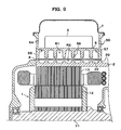
- FIG. 2 schematically shows a longitudinal, cross section, in an axial direction, of the drive unit according to a first embodiment.
- the reference numeral 1 denotes an electric motor, 11 a rotor shaft of the motor, 12 a rotor core, and 13 a stator core.
- the respective fins are shown, in all the drawings that include drawings showing embodiments described later, as being enlarged and exaggerated in dimension relative to the space R, and for the purpose of avoiding complexity in the drawings, the number of the fins is shown as being less than the number of fins actually arranged.
- Fig. 3 schematically shows a pattern of arrangement of the heat-sink side fins 56 as viewed in plan.
- the heat-sink side fins 56 comprise a multiplicity of pin-shaped fins in the form of a column arranged lengthwise and crosswise at a predetermined pitch relative to the first chamber R1 in order that flow in the first space R1 generate natural flow without restriction by the fins.
- Such adoption of pin-shaped fins is advantageous in that pressure loss in the refrigerant flow within the first space R1 can be extremely reduced.
- Fig. 4 shows, in plan, a modified example of a pattern of arrangement of the heat-sink side fins 56 in the same manner as in Fig. 3.
- the heat-sink side fins 56 comprise rib-shaped fins in the form of a plate, which are aligned in parallel between the inlet-side port 51 and the outlet-side port 52 and arranged at equal intervals, and both lengthwise ends of the fins terminate with a predetermined gap between them and the peripheral wall 55 of the heat sink 5 so that spaces between the respective fins 56 are communicated to the inlet-side port 51 and the outlet-side port 52.
- Such arrangement of the fins 56 defines in the first space R1 parallel flow passages, both ends of which are communicated to the inlet-side port 51 and the outlet-side port 52, and which are separated midway from one another by the fins 56.
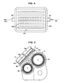
- Fig. 5 shows an example, in which the construction of the first embodiment is applied to a drive unit, for hybrid cars, provided with two electric motors.
- a motor 1A as a first electric motor is arranged in an upper position
- a differential device a position of a shaft of which is shown, is arranged substantially below the motor
- a generator 1B as a second electric motor is arranged in a middle position to be disposed forwardly thereof in a car-mounted state.
- a mount 20 for the heat sink 5 is formed integral with an upper portion of the drive unit casing 2.
- the mount 20 for the heat sink 5 is provided in a manner to project obliquely on the upper portion of the casing so as to contact with outer peripheries of two sections that receive the electric motors, and is in the form of a base, a plane outline of which substantially corresponds to that of the heat sink 5.
- a recess is formed on a side of a surface of the mount 20 that faces the heat sink 5, and this recess constitutes a second chamber (corresponding to the second chamber R2 in Fig. 2).
- the heat sink 5 comprises a member separate from the substrate of the inverter 3, is in the form of a casing provided with a peripheral wall 54 that is rectangular in plan, extends upward from a bottom wall 53 thereof in a manner to surround the outline in a frame-like manner, and has an interior thereof serving as a space that accommodates therein the inverter 3.
- two modules, for the motor and the generator, that constitute the inverter 3 are tightly fixed by appropriate means to the bottom wall 53 of the heat sink 5 that is finished flat so as to closely mount thereto the modules in a manner not to generate the resistance of heat conduction.
- an upper opening of the heat sink 5 is closed by a cover 7 so that the inverter 3 therein is protected from rain water and dust.
- a peripheral wall 55 that is rectangular in plan and extends downward in a manner to surround the outline thereof, whereby a first chamber (corresponding to the first chamber R1 in Fig. 2) of the space R is surrounded by the peripheral wall to be defined.
- the heat sink 5 constructed in this manner causes an end surface of the peripheral wall 55 to abut against a mount surface of the drive unit casing 2 with plate-shaped separation means 8 therebetween, the separation means 8 being externally dimensioned to correspond to a portion of the heat sink 5 opposed to the drive unit casing 2, that is, an external shape of the mount 20 of the drive unit casing 2, and also to an external shape, in plan, of the heat sink 5, and is subjected to sealing at a periphery thereof by a sealing material 9 (see Fig. 2) such as O-ring or the like at need, and fixed integrally by means of appropriate fixation means such as bolting, etc.
- a sealing material 9 see Fig. 2
- Fig. 6 shows a second embodiment that is the same in fundamental construction as the first embodiment.
- a heat sink 5 is the same as that in the first embodiment in comprising heat-sink side fins 56 extending into a first chamber R1
- a drive unit casing 2 also comprises drive-unit-casing side fins 22 extending into a second chamber R2.
- the drive-unit-casing side fins 22 are also apart from separation means 8. Since a remaining portion of the construction is the same as that in the first embodiment, an explanation is replaced by the same reference numerals that denote corresponding members. This is the same with other following embodiments.
- Fig. 7 shows, in schematic plan, an arrangement pattern adoptable in the embodiment, in which the heat-sink side fins 56 and the drive-unit-casing side fins 22 are arranged, andabottomsurface of the heat sink 5 and a mount surface on the side of the drive unit casing 2 actually in the opposed relationship with each other are aligned in the same plane.
- the heat-sink side fins 56 extending into the first chamber R1 comprise pin-shaped fins so as to reduce pressure loss in flow passages and the drive-unit-casing side fins 22 comprise rib-shaped fins that are excellent in making the flow uniform.
- flow resistance is smaller on a side of the first chamber R1 than on a side of the second chamber R2, so that the flow rate on the side of the first chamber R1 becomes relatively large and so cooling of an inverter 3 and the drive unit casing 2 can be efficiently carried out with less flow rate by increasing the cooling capacity on a side of the heat sink 5 to provide temperature gradient between the both chambers R1, R2 according to a low heat-resistant temperature of the inverter 3.
- Fig. 8 shows a modification, in which the fin arrangement pattern and the relationship of connection with the refrigerant circulating path are further changed, in the same manner as in Fig. 7.
- both the heat-sink side fins 56 extending into the first chamber R1 and the drive-unit-casing side fins 22 extending into the second chamber R2 comprise rib-shaped fins, while the heat-sink side fins 56 are arranged at smaller intervals than that for the drive-unit-casing side fins 22.
- the inlet port 51a of the first chamber R1 is connected to the discharge-side flow passage 43
- the outlet port 52a is connected to the inlet port 51b of the second chamber R2 via a connection flow passage 46
- the outlet port 51b of the second chamber R2 is connected to the return flow passage 44, and thus the both chambers are connected in series to the refrigerant circulating path.
- a cooling area (a fin surface area in contact with the refrigerant) on the side of the first chamber R1 is larger than that on the side of the second chamber R2 even when the both chambers R1, R2 are equal to each other in thickness, so that a cooling effect on the side of the first chamber R1 becomes relatively large. Accordingly, making use of the above, cooling of the inverter 3 and the drive unit casing 2 can be efficiently carried out with less flow rate in the same manner as the case described above by increasing the cooling capacity on a side of the heat sink 5 to provide temperature gradient between the both chambers according to a low heat-resistant temperature of the inverter 3.
- connection of the both chambers R1, R2 to the refrigerant circulating path can be appropriately selected according to the relationship of the cooling effect as aimed at and a fin arrangement pattern as employed.
- FIG. 9 shows a modification, in which the second embodiment is made further concrete.
- this modification illustrates the case where a heat sink is composed of a module substrate itself with respect to unification of a substrate of an inverter with a heat sink.
- the heat sink 5 since the heat sink 5 is annexed to a side of the inverter 3, the heat sink 5 is fixed to an inverter casing 50 comprising a separate member from the heat sink and mounted to a drive unit casing 2 through the inverter casing 50.
- the drive unit casing 2 in this modification is the same as that in the previous embodiment in substantial construction while a mount 20 in an upper portion of the drive unit casing serves a mount for the inverter casing 50.
- the mount 20 for the inverter casing 50 is in the form of a base, a plane outline of which substantially corresponds to that of the inverter casing 50.
- a recess is formed on a side of a surface of the mount 20 that faces the heat sink 5, and this recess constitutes a second chamber (corresponding to the second chamber R2 in Fig. 6).
- appropriate sealing means of which illustration is omitted, is inserted in a fixing portion of the shelf-shaped portion 57 around the heat sink 5, to which the heat sink 5 is to be fixed, and thus sealing is applied between the inverter casing 50 and the heat sink 5.
- a first chamber (corresponding to the first chamber R1 in fig. 6) of a space R is surrounded and defined by an underside of the heat sink 5 and a rectangular-shaped peripheral wall 55 below the shelf-shaped portion 57 of the inverter casing 50.
- both the two embodiments described above make exclusive use of a refrigerant as a layer of thermal insulation without taking account of the heat conductive property of the separation means 8.
- a low thermal conductive member 6 made of a material of low thermal conductivity that is, a thermal insulating material is used for the separation means 8
- a low thermal conductive member, such as film-shapedmember or the like, made of a material of low thermal conductivity is provided along and arranged on a member of a metallic material, etc. that constitutes separation means 8 as a backing
- at least drive-unit-side fins 22 can be configured to contact directly with a low thermal conductive member 6 that constitutes the separation means 8, or a member provided along the low thermal conductive member.
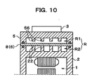
- a third embodiment shown in Fig. 10 adopts such construction.
- the low thermal conductive member 6 referred herein to does not necessarily means a member made of a single material but includes a member formed by laminating a plurality of different materials that include coating, etc.
- the third embodiment adopts a construction, in which the separation means 8 comprises a low thermal conductive member 6 made of a material of low thermal conductivity, and tip ends of drive-unit-side fins 22 contact with the low thermal conductive member 6.
- the separation means 8 comprises the low thermal conductive member 6
- any special consideration is not necessarily taken of a contact area of the tip ends of the drive-unit-side fins 22 with the separation means 8.
- an arrangement pattern of the drive-unit-side fins 22 is composed of pin-shaped fins.
- the separation means 8 that separates the first chamber R1 and the second chamber R2 from each other serves as the thermal insulating material 6 for a thermal insulating layer
- three thermal insulation layers in all including two layers of the refrigerant and a layer formed from the low thermal conductive member 6 are provided between the drive unit casing 2 and the heat sink 5 to further improve the effect of thermal insulation.
- the low thermal conductive member being film-shaped or the like is arranged on a side in contact with the drive-unit-casing side fins 22, tip ends of the drive-unit-casing side fins 22 support the low thermal conductive member, so that floating of the low thermal conductive member from the separation means 8 can be prevented without the use of any special sticking means such as adhesion or the like.
- the separation means in the first and second embodiments is exemplarily composed of a single-layeredmember, it can be composed of a multi-layered member, or constructed therefrom.
- the separation means be composed of, for example, a plurality of separation members with low thermal conductive portions therebetween, and the low thermal conductive portions be made, for example, a solid thermal insulating material, or a refrigerant flowing space similar to the first chamber R1 and the second chamber R2.
- the low thermal conductive member 6 in the third embodiment comprises a film-shaped member or coating itself having no rigidity
- the low thermal conductive member 6 is provided along or interposed between the separation means 8 made of an appropriate material such as metallic material, ceramic material, rubber, etc.
- the low thermal conductive member 6 may be provided along one surface of the separation means 8 or both surfaces thereof.
- the invention is widely applicable to apparatuses, in which an electric motor and an inverter are united together, as well as drive units for electric cars and hybrid drive units.
Landscapes
- Engineering & Computer Science (AREA)
- Power Engineering (AREA)
- Microelectronics & Electronic Packaging (AREA)
- Combustion & Propulsion (AREA)
- Transportation (AREA)
- Mechanical Engineering (AREA)
- Chemical & Material Sciences (AREA)
- Physics & Mathematics (AREA)
- Thermal Sciences (AREA)
- Motor Or Generator Cooling System (AREA)
- Inverter Devices (AREA)
- Cooling Or The Like Of Electrical Apparatus (AREA)
- Cooling Or The Like Of Semiconductors Or Solid State Devices (AREA)
Abstract
Description
Claims (6)
- A drive unit including
an electric motor (1),
a drive unit casing (2) accommodating therein the electric motor,
an inverter (3) that controls the electric motor, and
a flowpassage (4) of a refrigerant that cools the inverter, the drive unit characterized in that the inverter is mounted on the drive unit casing such that a heat sink (5) united with a substrate of the inverter defines a space (R) on a portion thereof opposed to the drive unit casing,
the space is compartmented by separation means (8) into a first chamber (R1) facing the heat sink and a second chamber (R2) facing the drive unit casing, and communicated to the flow passage of the refrigerant, and
the heat sink comprises heat-sink side fins (56) extending into the first chamber and apart from the separation means. - The drive unit according to claim 1, wherein the drive unit casing comprises drive-unit-side fins (22) extending into the second chamber.
- The drive unit according to claim 2, wherein the drive-unit-side fins are apart from the separation means.
- The drive unit according to claim 1, 2 or 3, wherein the separation means comprises a low thermal conductive member (6) made of a material of low thermal conductivity.
- The drive unit according to claim 1, 2, or 3, wherein the separation means comprises a separation member and a low thermal conductive member provided along the separation member and made of a material of low thermal conductivity.
- The drive unit according to claim 1, 2, or 3, wherein the separation means comprises separation members with a low thermal conductive portion there between.
Applications Claiming Priority (3)
| Application Number | Priority Date | Filing Date | Title |
|---|---|---|---|
| JP2002269232 | 2002-09-13 | ||
| JP2002269232 | 2002-09-13 | ||
| PCT/JP2003/005749 WO2004025809A1 (en) | 2002-09-13 | 2003-05-08 | Drive device |
Publications (3)
| Publication Number | Publication Date |
|---|---|
| EP1538731A1 true EP1538731A1 (en) | 2005-06-08 |
| EP1538731A4 EP1538731A4 (en) | 2006-02-15 |
| EP1538731B1 EP1538731B1 (en) | 2008-07-16 |
Family
ID=31986811
Family Applications (1)
| Application Number | Title | Priority Date | Filing Date |
|---|---|---|---|
| EP03721070A Expired - Lifetime EP1538731B1 (en) | 2002-09-13 | 2003-05-08 | Drive device |
Country Status (7)
| Country | Link |
|---|---|
| US (1) | US7030520B2 (en) |
| EP (1) | EP1538731B1 (en) |
| JP (1) | JP4096267B2 (en) |
| KR (1) | KR100614011B1 (en) |
| CN (1) | CN100353648C (en) |
| DE (1) | DE60322232D1 (en) |
| WO (1) | WO2004025809A1 (en) |
Families Citing this family (62)
| Publication number | Priority date | Publication date | Assignee | Title |
|---|---|---|---|---|
| JPH09154694A (en) * | 1995-12-08 | 1997-06-17 | Tomokazu Uchiyama | Salad container |
| JP4687106B2 (en) * | 2004-12-28 | 2011-05-25 | マックス株式会社 | Air compressor cooling system |
| JP4106061B2 (en) * | 2005-04-22 | 2008-06-25 | 三菱電機株式会社 | Power unit device and power conversion device |
| US7798892B2 (en) * | 2005-08-31 | 2010-09-21 | Siemens Industry, Inc. | Packaging method for modular power cells |
| DE502005002315D1 (en) * | 2005-10-12 | 2008-01-31 | Bayerische Motoren Werke Ag | Cooling device for a motor vehicle with a drive consisting of two motors |
| US7295440B2 (en) * | 2006-03-07 | 2007-11-13 | Honeywell International, Inc. | Integral cold plate/chasses housing applicable to force-cooled power electronics |
| JP4850564B2 (en) | 2006-04-06 | 2012-01-11 | 日立オートモティブシステムズ株式会社 | Power converter |
| JP4857017B2 (en) * | 2006-04-27 | 2012-01-18 | 日立オートモティブシステムズ株式会社 | Power converter |
| JP4675311B2 (en) * | 2006-11-16 | 2011-04-20 | トヨタ自動車株式会社 | Inverter and condenser cooling structure accommodated integrally with motor in motor housing, motor unit and housing having the cooling structure |
| US8007255B2 (en) * | 2006-11-22 | 2011-08-30 | Mitsubishi Heavy Industries, Ltd. | Inverter-integrated electric compressor with inverter storage box arrangement |
| JP5024600B2 (en) * | 2007-01-11 | 2012-09-12 | アイシン・エィ・ダブリュ株式会社 | Heating element cooling structure and driving device having the structure |
| JP5099417B2 (en) * | 2007-05-22 | 2012-12-19 | アイシン・エィ・ダブリュ株式会社 | Semiconductor module and inverter device |
| JP4678385B2 (en) * | 2007-06-13 | 2011-04-27 | トヨタ自動車株式会社 | DRIVE DEVICE AND VEHICLE HAVING DRIVE DEVICE |
| US7723874B2 (en) * | 2008-02-15 | 2010-05-25 | Gm Global Technology Operations, Inc. | Cooling systems and methods for integration electric motor-inverters |
| JP5099431B2 (en) * | 2008-02-15 | 2012-12-19 | アイシン・エィ・ダブリュ株式会社 | Inverter unit |
| JP2009247119A (en) * | 2008-03-31 | 2009-10-22 | Aisin Aw Co Ltd | Drive device |
| JP4708487B2 (en) * | 2009-07-06 | 2011-06-22 | トヨタ自動車株式会社 | Inverter relay connection member |
| US8064198B2 (en) * | 2009-06-29 | 2011-11-22 | Honda Motor Co., Ltd. | Cooling device for semiconductor element module and magnetic part |
| KR20110053084A (en) * | 2009-11-13 | 2011-05-19 | 엘지전자 주식회사 | Power module and automobile comprising the same |
| JP2011130545A (en) * | 2009-12-16 | 2011-06-30 | Toyota Industries Corp | Heat recovery device |
| US20110200467A1 (en) * | 2010-02-16 | 2011-08-18 | Heng Sheng Precision Tech. Co., Ltd. | Power driven compressor that prevents overheating of control circuit |
| WO2011101222A1 (en) * | 2010-02-19 | 2011-08-25 | Magna Powertrain Ag & Co Kg | Electric drive unit |
| CN102934334A (en) * | 2010-05-04 | 2013-02-13 | 瑞美技术有限责任公司 | Electric machine cooling system and method |
| CN103338962A (en) * | 2011-01-27 | 2013-10-02 | 丰田自动车株式会社 | Cooling apparatus |
| JP5716825B2 (en) * | 2011-05-12 | 2015-05-13 | トヨタ自動車株式会社 | Cooler and method for manufacturing cooler |
| KR20140061398A (en) * | 2011-08-15 | 2014-05-21 | 누보 피그노네 에스피에이 | Mixing manifold and method |
| CN103023279B (en) * | 2011-09-27 | 2015-05-13 | 株式会社京浜 | Semiconductor control device |
| US9048721B2 (en) * | 2011-09-27 | 2015-06-02 | Keihin Corporation | Semiconductor device |
| ITTO20110924A1 (en) * | 2011-10-14 | 2013-04-15 | Merlo Project S R L Con Unico Socio | ELECTRO-HYDRAULIC HYBRID WORKING MACHINE |
| JP2013216216A (en) * | 2012-04-10 | 2013-10-24 | Ntn Corp | Cooling structure of inverter device |
| FR2991009B1 (en) * | 2012-05-22 | 2014-05-16 | Valeo Sys Controle Moteur Sas | ELECTRIC COMPRESSOR HOUSING COMPRISING A DISSIPATION DEVICE, AND COMPRESSOR COMPRISING SUCH A HOUSING |
| JP6079190B2 (en) * | 2012-12-10 | 2017-02-15 | アイシン・エィ・ダブリュ株式会社 | Vehicle drive device |
| JP6042746B2 (en) * | 2013-02-25 | 2016-12-14 | 愛三工業株式会社 | Electric pump |
| ES2555121T3 (en) * | 2013-07-08 | 2015-12-29 | Fagor, S. Coop. | Electric drive device |
| US10348161B2 (en) | 2013-11-26 | 2019-07-09 | Schaeffler Technologies AG & Co. KG | Hybrid module and power electronics module with a shared cooling stream |
| EP2879278B1 (en) * | 2013-11-27 | 2017-06-28 | Skf Magnetic Mechatronics | Versatile cooling housing for an electrical motor |
| JP5907151B2 (en) * | 2013-11-29 | 2016-04-20 | トヨタ自動車株式会社 | Car electronics case |
| DE102013225242B4 (en) * | 2013-12-09 | 2019-05-16 | Continental Automotive Gmbh | Charging device for an internal combustion engine of a motor vehicle and method for producing the charging device |
| DE112015006041B4 (en) * | 2015-01-22 | 2021-03-11 | Mitsubishi Electric Corporation | Semiconductor device |
| CN107206884B (en) * | 2015-01-28 | 2019-09-06 | 本田技研工业株式会社 | Drive device for hybrid vehicle |
| DE102015214770A1 (en) * | 2015-08-03 | 2017-02-09 | Zf Friedrichshafen Ag | Housing for a drive unit for a vehicle, drive unit for a vehicle and method for producing a drive unit for a vehicle |
| DE102015226023A1 (en) * | 2015-12-18 | 2017-06-22 | Siemens Aktiengesellschaft | Liquid-cooled, electric drive component, powertrain, vehicle and process |
| DE102017103475A1 (en) * | 2016-02-25 | 2017-08-31 | Toyota Jidosha Kabushiki Kaisha | unit |
| JP6756382B2 (en) * | 2017-01-25 | 2020-09-16 | 株式会社Ihi | Electric compressor |
| CN106972698A (en) * | 2017-04-07 | 2017-07-21 | 上海蔚来汽车有限公司 | Electromotor cooling system |
| DE102017208632A1 (en) * | 2017-05-22 | 2018-11-22 | Audi Ag | Motor vehicle and converter device for a motor vehicle |
| JP6984383B2 (en) * | 2017-12-15 | 2021-12-17 | 株式会社Ihi | Rotating machine |
| DE102018114825A1 (en) * | 2018-06-20 | 2019-12-24 | Valeo Siemens Eautomotive Germany Gmbh | Cooling device for a rotating electrical machine and rotating electrical machine for driving a vehicle |
| JP7084810B2 (en) * | 2018-07-13 | 2022-06-15 | 本田技研工業株式会社 | Drive unit |
| CN109616859A (en) * | 2019-01-29 | 2019-04-12 | 中山铟尼镭斯科技有限公司 | A kind of optical fiber femtosecond laser |
| US11746636B2 (en) | 2019-10-30 | 2023-09-05 | Yantai Jereh Petroleum Equipment & Technologies Co., Ltd. | Fracturing apparatus and control method thereof, fracturing system |
| US11680474B2 (en) | 2019-06-13 | 2023-06-20 | Yantai Jereh Petroleum Equipment & Technologies Co., Ltd. | Fracturing apparatus and control method thereof, fracturing system |
| US10965183B2 (en) | 2019-06-14 | 2021-03-30 | Honeywell International Inc. | Integrated traction drive system |
| DE102019212118A1 (en) * | 2019-08-13 | 2021-02-18 | Mahle International Gmbh | Electric machine with an annular heat exchanger |
| FR3111027B1 (en) * | 2020-05-29 | 2022-05-27 | Novares France | Electric motorization device incorporating an electrically insulating heat sink |
| DE102020121432B4 (en) * | 2020-08-14 | 2022-06-09 | Dr. Ing. H.C. F. Porsche Aktiengesellschaft | Drive train with an electric machine and an inverter, motor vehicle |
| JP7322841B2 (en) * | 2020-09-17 | 2023-08-08 | 株式会社デンソー | Rotating electric machine unit |
| CN112248781A (en) * | 2020-10-27 | 2021-01-22 | 株洲中车时代电气股份有限公司 | Integrated electric driving system and integrated cooling device thereof |
| US11757334B2 (en) * | 2020-10-29 | 2023-09-12 | Dana Belgium N.V. | Systems and method for an electric motor with pin-fin cooling |
| US11894756B2 (en) | 2021-01-25 | 2024-02-06 | Honeywell International Inc. | Systems and methods for electric propulsion systems for electric engines |
| JP2023015907A (en) * | 2021-07-20 | 2023-02-01 | ヤマハ発動機株式会社 | Drive unit and electric vehicle |
| CA3179258A1 (en) | 2021-10-14 | 2023-04-14 | Yantai Jereh Petroleum Equipment & Technologies Co., Ltd. | A fracturing device driven by a variable-frequency adjustable-speed integrated machine and a well site layout |
Citations (1)
| Publication number | Priority date | Publication date | Assignee | Title |
|---|---|---|---|---|
| US6039114A (en) * | 1996-01-04 | 2000-03-21 | Daimler - Benz Aktiengesellschaft | Cooling body having lugs |
Family Cites Families (16)
| Publication number | Priority date | Publication date | Assignee | Title |
|---|---|---|---|---|
| JPH05292703A (en) | 1992-04-09 | 1993-11-05 | Toyota Motor Corp | Motor for electric vehicle |
| JPH06326226A (en) * | 1993-03-15 | 1994-11-25 | Toshiba Corp | Cooling unit |
| ATA105093A (en) * | 1993-05-28 | 2001-07-15 | Steyr Daimler Puch Ag | LIQUID-COOLED DRIVE UNIT FOR AN ELECTROMOBILE |
| US5491370A (en) * | 1994-01-28 | 1996-02-13 | General Motors Corporation | Integrated AC machine |
| JPH07288949A (en) | 1994-04-13 | 1995-10-31 | Nippondenso Co Ltd | Electric motor to drive vehicle |
| JP3508206B2 (en) * | 1994-04-27 | 2004-03-22 | 株式会社デンソー | Motor for driving vehicle |
| DE69623111T2 (en) * | 1995-12-21 | 2003-05-08 | Aisin Aw Co., Ltd. | DRIVE DEVICE FOR ELECTRIC MOTOR VEHICLES |
| JP3309684B2 (en) * | 1995-12-26 | 2002-07-29 | アイシン・エィ・ダブリュ株式会社 | Motor drive |
| FR2775416B1 (en) * | 1998-02-23 | 2000-06-23 | Gec Alsthom Transport Sa | COOLING ELEMENT FOR ELECTRONIC POWER DEVICE AND ELECTRONIC POWER DEVICE COMPRISING SUCH AN ELEMENT |
| DE19817333C5 (en) * | 1998-04-18 | 2007-04-26 | Conti Temic Microelectronic Gmbh | Electric drive unit consisting of electric motor and electronic module |
| JP3886696B2 (en) | 1999-04-27 | 2007-02-28 | アイシン・エィ・ダブリュ株式会社 | Drive device |
| JP3886697B2 (en) * | 1999-04-27 | 2007-02-28 | アイシン・エィ・ダブリュ株式会社 | Drive device |
| JP2001119898A (en) | 1999-10-18 | 2001-04-27 | Aisin Aw Co Ltd | Driver |
| FR2805121B1 (en) * | 2000-02-11 | 2002-04-26 | Leroy Somer | MODULAR CONVERTER |
| US6414867B2 (en) * | 2000-02-16 | 2002-07-02 | Hitachi, Ltd. | Power inverter |
| JP3891348B2 (en) * | 2002-12-27 | 2007-03-14 | アイシン・エィ・ダブリュ株式会社 | Electric drive |
-
2003
- 2003-05-08 KR KR1020047010828A patent/KR100614011B1/en not_active IP Right Cessation
- 2003-05-08 JP JP2004535861A patent/JP4096267B2/en not_active Expired - Fee Related
- 2003-05-08 CN CNB038021889A patent/CN100353648C/en not_active Expired - Fee Related
- 2003-05-08 EP EP03721070A patent/EP1538731B1/en not_active Expired - Lifetime
- 2003-05-08 DE DE60322232T patent/DE60322232D1/en not_active Expired - Lifetime
- 2003-05-08 WO PCT/JP2003/005749 patent/WO2004025809A1/en active IP Right Grant
- 2003-05-08 US US10/501,073 patent/US7030520B2/en not_active Expired - Fee Related
Patent Citations (1)
| Publication number | Priority date | Publication date | Assignee | Title |
|---|---|---|---|---|
| US6039114A (en) * | 1996-01-04 | 2000-03-21 | Daimler - Benz Aktiengesellschaft | Cooling body having lugs |
Non-Patent Citations (2)
| Title |
|---|
| PATENT ABSTRACTS OF JAPAN vol. 1997, no. 11, 28 November 1997 (1997-11-28) & JP 09 182352 A (AISIN AW CO LTD), 11 July 1997 (1997-07-11) * |
| See also references of WO2004025809A1 * |
Also Published As
| Publication number | Publication date |
|---|---|
| EP1538731B1 (en) | 2008-07-16 |
| US20050006963A1 (en) | 2005-01-13 |
| WO2004025809A1 (en) | 2004-03-25 |
| DE60322232D1 (en) | 2008-08-28 |
| JP4096267B2 (en) | 2008-06-04 |
| CN1615569A (en) | 2005-05-11 |
| CN100353648C (en) | 2007-12-05 |
| US7030520B2 (en) | 2006-04-18 |
| JPWO2004025809A1 (en) | 2006-01-12 |
| KR20050036906A (en) | 2005-04-20 |
| EP1538731A4 (en) | 2006-02-15 |
| KR100614011B1 (en) | 2006-08-21 |
Similar Documents
| Publication | Publication Date | Title |
|---|---|---|
| EP1538731B1 (en) | Drive device | |
| US7525224B2 (en) | Drive unit and inverter with cooling technique | |
| US7102260B2 (en) | Drive device | |
| JP5024600B2 (en) | Heating element cooling structure and driving device having the structure | |
| JP4186109B2 (en) | Drive device | |
| JP2006202899A (en) | Semiconductor cooling apparatus | |
| JP2009152440A (en) | Temperature regulator for heating element | |
| JP4683003B2 (en) | Power module and power converter using the same | |
| JP5712750B2 (en) | Power converter | |
| JP4075702B2 (en) | Power converter | |
| CN114285297A (en) | Inverter, power assembly and electric vehicle | |
| US11785737B2 (en) | Systems and methods for cooling electronic components of a vehicle | |
| US11950398B2 (en) | Systems and methods for cooling electronic components of a vehicle | |
| CN116469680A (en) | System and method for cooling electrical components of a vehicle | |
| JP2021111709A (en) | Power conversion apparatus |
Legal Events
| Date | Code | Title | Description |
|---|---|---|---|
| PUAI | Public reference made under article 153(3) epc to a published international application that has entered the european phase |
Free format text: ORIGINAL CODE: 0009012 |
|
| 17P | Request for examination filed |
Effective date: 20050413 |
|
| AK | Designated contracting states |
Kind code of ref document: A1 Designated state(s): AT BE BG CH CY CZ DE DK EE ES FI FR GB GR HU IE IT LI LU MC NL PT RO SE SI SK TR |
|
| AX | Request for extension of the european patent |
Extension state: AL LT LV MK |
|
| DAX | Request for extension of the european patent (deleted) | ||
| RBV | Designated contracting states (corrected) |
Designated state(s): DE FR GB |
|
| A4 | Supplementary search report drawn up and despatched |
Effective date: 20060102 |
|
| 17Q | First examination report despatched |
Effective date: 20070330 |
|
| GRAP | Despatch of communication of intention to grant a patent |
Free format text: ORIGINAL CODE: EPIDOSNIGR1 |
|
| GRAS | Grant fee paid |
Free format text: ORIGINAL CODE: EPIDOSNIGR3 |
|
| GRAA | (expected) grant |
Free format text: ORIGINAL CODE: 0009210 |
|
| AK | Designated contracting states |
Kind code of ref document: B1 Designated state(s): DE FR GB |
|
| REG | Reference to a national code |
Ref country code: GB Ref legal event code: FG4D |
|
| REF | Corresponds to: |
Ref document number: 60322232 Country of ref document: DE Date of ref document: 20080828 Kind code of ref document: P |
|
| PLBE | No opposition filed within time limit |
Free format text: ORIGINAL CODE: 0009261 |
|
| STAA | Information on the status of an ep patent application or granted ep patent |
Free format text: STATUS: NO OPPOSITION FILED WITHIN TIME LIMIT |
|
| 26N | No opposition filed |
Effective date: 20090417 |
|
| PGFP | Annual fee paid to national office [announced via postgrant information from national office to epo] |
Ref country code: GB Payment date: 20140507 Year of fee payment: 12 |
|
| PGFP | Annual fee paid to national office [announced via postgrant information from national office to epo] |
Ref country code: DE Payment date: 20140430 Year of fee payment: 12 Ref country code: FR Payment date: 20140509 Year of fee payment: 12 |
|
| REG | Reference to a national code |
Ref country code: DE Ref legal event code: R119 Ref document number: 60322232 Country of ref document: DE |
|
| GBPC | Gb: european patent ceased through non-payment of renewal fee |
Effective date: 20150508 |
|
| REG | Reference to a national code |
Ref country code: FR Ref legal event code: ST Effective date: 20160129 |
|
| PG25 | Lapsed in a contracting state [announced via postgrant information from national office to epo] |
Ref country code: DE Free format text: LAPSE BECAUSE OF NON-PAYMENT OF DUE FEES Effective date: 20151201 Ref country code: GB Free format text: LAPSE BECAUSE OF NON-PAYMENT OF DUE FEES Effective date: 20150508 |
|
| PG25 | Lapsed in a contracting state [announced via postgrant information from national office to epo] |
Ref country code: FR Free format text: LAPSE BECAUSE OF NON-PAYMENT OF DUE FEES Effective date: 20150601 |