EP1538386B1 - Stand - Google Patents
Stand Download PDFInfo
- Publication number
- EP1538386B1 EP1538386B1 EP05000973A EP05000973A EP1538386B1 EP 1538386 B1 EP1538386 B1 EP 1538386B1 EP 05000973 A EP05000973 A EP 05000973A EP 05000973 A EP05000973 A EP 05000973A EP 1538386 B1 EP1538386 B1 EP 1538386B1
- Authority
- EP
- European Patent Office
- Prior art keywords
- axis
- support
- support according
- weight
- carrier arm
- Prior art date
- Legal status (The legal status is an assumption and is not a legal conclusion. Google has not performed a legal analysis and makes no representation as to the accuracy of the status listed.)
- Expired - Lifetime
Links
Images
Classifications
-
- F—MECHANICAL ENGINEERING; LIGHTING; HEATING; WEAPONS; BLASTING
- F16—ENGINEERING ELEMENTS AND UNITS; GENERAL MEASURES FOR PRODUCING AND MAINTAINING EFFECTIVE FUNCTIONING OF MACHINES OR INSTALLATIONS; THERMAL INSULATION IN GENERAL
- F16M—FRAMES, CASINGS OR BEDS OF ENGINES, MACHINES OR APPARATUS, NOT SPECIFIC TO ENGINES, MACHINES OR APPARATUS PROVIDED FOR ELSEWHERE; STANDS; SUPPORTS
- F16M13/00—Other supports for positioning apparatus or articles; Means for steadying hand-held apparatus or articles
- F16M13/02—Other supports for positioning apparatus or articles; Means for steadying hand-held apparatus or articles for supporting on, or attaching to, an object, e.g. tree, gate, window-frame, cycle
-
- A—HUMAN NECESSITIES
- A61—MEDICAL OR VETERINARY SCIENCE; HYGIENE
- A61B—DIAGNOSIS; SURGERY; IDENTIFICATION
- A61B90/00—Instruments, implements or accessories specially adapted for surgery or diagnosis and not covered by any of the groups A61B1/00 - A61B50/00, e.g. for luxation treatment or for protecting wound edges
- A61B90/20—Surgical microscopes characterised by non-optical aspects
- A61B90/25—Supports therefor
-
- F—MECHANICAL ENGINEERING; LIGHTING; HEATING; WEAPONS; BLASTING
- F16—ENGINEERING ELEMENTS AND UNITS; GENERAL MEASURES FOR PRODUCING AND MAINTAINING EFFECTIVE FUNCTIONING OF MACHINES OR INSTALLATIONS; THERMAL INSULATION IN GENERAL
- F16M—FRAMES, CASINGS OR BEDS OF ENGINES, MACHINES OR APPARATUS, NOT SPECIFIC TO ENGINES, MACHINES OR APPARATUS PROVIDED FOR ELSEWHERE; STANDS; SUPPORTS
- F16M11/00—Stands or trestles as supports for apparatus or articles placed thereon Stands for scientific apparatus such as gravitational force meters
- F16M11/02—Heads
- F16M11/04—Means for attachment of apparatus; Means allowing adjustment of the apparatus relatively to the stand
- F16M11/06—Means for attachment of apparatus; Means allowing adjustment of the apparatus relatively to the stand allowing pivoting
- F16M11/10—Means for attachment of apparatus; Means allowing adjustment of the apparatus relatively to the stand allowing pivoting around a horizontal axis
-
- F—MECHANICAL ENGINEERING; LIGHTING; HEATING; WEAPONS; BLASTING
- F16—ENGINEERING ELEMENTS AND UNITS; GENERAL MEASURES FOR PRODUCING AND MAINTAINING EFFECTIVE FUNCTIONING OF MACHINES OR INSTALLATIONS; THERMAL INSULATION IN GENERAL
- F16M—FRAMES, CASINGS OR BEDS OF ENGINES, MACHINES OR APPARATUS, NOT SPECIFIC TO ENGINES, MACHINES OR APPARATUS PROVIDED FOR ELSEWHERE; STANDS; SUPPORTS
- F16M11/00—Stands or trestles as supports for apparatus or articles placed thereon Stands for scientific apparatus such as gravitational force meters
- F16M11/20—Undercarriages with or without wheels
- F16M11/2007—Undercarriages with or without wheels comprising means allowing pivoting adjustment
- F16M11/2021—Undercarriages with or without wheels comprising means allowing pivoting adjustment around a horizontal axis
-
- F—MECHANICAL ENGINEERING; LIGHTING; HEATING; WEAPONS; BLASTING
- F16—ENGINEERING ELEMENTS AND UNITS; GENERAL MEASURES FOR PRODUCING AND MAINTAINING EFFECTIVE FUNCTIONING OF MACHINES OR INSTALLATIONS; THERMAL INSULATION IN GENERAL
- F16M—FRAMES, CASINGS OR BEDS OF ENGINES, MACHINES OR APPARATUS, NOT SPECIFIC TO ENGINES, MACHINES OR APPARATUS PROVIDED FOR ELSEWHERE; STANDS; SUPPORTS
- F16M11/00—Stands or trestles as supports for apparatus or articles placed thereon Stands for scientific apparatus such as gravitational force meters
- F16M11/20—Undercarriages with or without wheels
- F16M11/2007—Undercarriages with or without wheels comprising means allowing pivoting adjustment
- F16M11/2035—Undercarriages with or without wheels comprising means allowing pivoting adjustment in more than one direction
- F16M11/2064—Undercarriages with or without wheels comprising means allowing pivoting adjustment in more than one direction for tilting and panning
-
- F—MECHANICAL ENGINEERING; LIGHTING; HEATING; WEAPONS; BLASTING
- F16—ENGINEERING ELEMENTS AND UNITS; GENERAL MEASURES FOR PRODUCING AND MAINTAINING EFFECTIVE FUNCTIONING OF MACHINES OR INSTALLATIONS; THERMAL INSULATION IN GENERAL
- F16M—FRAMES, CASINGS OR BEDS OF ENGINES, MACHINES OR APPARATUS, NOT SPECIFIC TO ENGINES, MACHINES OR APPARATUS PROVIDED FOR ELSEWHERE; STANDS; SUPPORTS
- F16M11/00—Stands or trestles as supports for apparatus or articles placed thereon Stands for scientific apparatus such as gravitational force meters
- F16M11/20—Undercarriages with or without wheels
- F16M11/2007—Undercarriages with or without wheels comprising means allowing pivoting adjustment
- F16M11/2035—Undercarriages with or without wheels comprising means allowing pivoting adjustment in more than one direction
- F16M11/2078—Undercarriages with or without wheels comprising means allowing pivoting adjustment in more than one direction with ball-joint
-
- F—MECHANICAL ENGINEERING; LIGHTING; HEATING; WEAPONS; BLASTING
- F16—ENGINEERING ELEMENTS AND UNITS; GENERAL MEASURES FOR PRODUCING AND MAINTAINING EFFECTIVE FUNCTIONING OF MACHINES OR INSTALLATIONS; THERMAL INSULATION IN GENERAL
- F16M—FRAMES, CASINGS OR BEDS OF ENGINES, MACHINES OR APPARATUS, NOT SPECIFIC TO ENGINES, MACHINES OR APPARATUS PROVIDED FOR ELSEWHERE; STANDS; SUPPORTS
- F16M13/00—Other supports for positioning apparatus or articles; Means for steadying hand-held apparatus or articles
- F16M13/02—Other supports for positioning apparatus or articles; Means for steadying hand-held apparatus or articles for supporting on, or attaching to, an object, e.g. tree, gate, window-frame, cycle
- F16M13/027—Ceiling supports
-
- G—PHYSICS
- G02—OPTICS
- G02B—OPTICAL ELEMENTS, SYSTEMS OR APPARATUS
- G02B7/00—Mountings, adjusting means, or light-tight connections, for optical elements
- G02B7/001—Counterbalanced structures, e.g. surgical microscopes
-
- A—HUMAN NECESSITIES
- A61—MEDICAL OR VETERINARY SCIENCE; HYGIENE
- A61B—DIAGNOSIS; SURGERY; IDENTIFICATION
- A61B90/00—Instruments, implements or accessories specially adapted for surgery or diagnosis and not covered by any of the groups A61B1/00 - A61B50/00, e.g. for luxation treatment or for protecting wound edges
- A61B90/20—Surgical microscopes characterised by non-optical aspects
-
- F—MECHANICAL ENGINEERING; LIGHTING; HEATING; WEAPONS; BLASTING
- F16—ENGINEERING ELEMENTS AND UNITS; GENERAL MEASURES FOR PRODUCING AND MAINTAINING EFFECTIVE FUNCTIONING OF MACHINES OR INSTALLATIONS; THERMAL INSULATION IN GENERAL
- F16M—FRAMES, CASINGS OR BEDS OF ENGINES, MACHINES OR APPARATUS, NOT SPECIFIC TO ENGINES, MACHINES OR APPARATUS PROVIDED FOR ELSEWHERE; STANDS; SUPPORTS
- F16M2200/00—Details of stands or supports
- F16M2200/04—Balancing means
- F16M2200/044—Balancing means for balancing rotational movement of the undercarriage
Definitions
- the invention relates to a stand, in particular for receiving a medical device, for example a surgical microscope, with a column stand on which a first support arm is arranged and with a second support arm which is received on the first support arm and relative to the first support arm about a first Axis and about a second axis different from the first axis, wherein for generating a restoring force for the second support arm about the first axis, a movable weight is provided, and means are provided for coupling, which the weight with a movement of the second Couple low-arm around the first axis.
- a medical device for example a surgical microscope
- Such a tripod is from the US 4,548,373 known.
- a tripod for a surgical microscope which has a first column stand on which a first pivot arm is pivotally received about a vertical axis of rotation.
- This first support arm carries with one end portion a second support arm.
- This second carrier arm can be moved relative to the first carrier arm in a joint receptacle about a first horizontally oriented axis of rotation and about a further axis of rotation perpendicular to the first horizontally oriented axis of rotation.
- On the second support arm is a balance weight, which serves to compensate for the recorded on the second support arm load weight of the surgical microscope.
- a tripod for receiving a lighting unit known.
- This tripod comprises a column stand, on which a support arm is received.
- This support arm can be rotated with respect to the column stand in a horizontal plane and pivoted in a vertical plane to the column stand.
- a movably arranged weight is provided on the stator column and is operatively connected to the carrier arm.
- the US 5,494,034 discloses a floor stand comprising a column stand on which a support device with a first and a second support arm is arranged.
- the first carrier arm is rotatably mounted on the column stand.
- the second carrier arm is pivotably mounted and movable with respect to two axes orthogonal to the first carrier arm.
- a third support arm in turn is rotatably mounted at one end of the second support arm and holds with a hinge a surgical instrument.
- This weight-balancing mechanism comprises two balance weights received on lever arms and supported by a fork-shaped holding device from the first carrier arm in the region of a hinge connection from the first and second carrier arms.
- a ground stand with counterbalance for receiving a surgical microscope known.
- This stand has a column stand on which a fortunevorraum is received with a first and a second support arm.
- the first support arm is pivotally mounted on the column stand.
- the second carrier arm is in turn rotatably mounted on the first carrier arm.
- the surgical microscope is received in an end region of the second carrier arm.
- counterweights are provided on the first and second support arm.
- the object of the invention is to provide a tripod, on the one hand has space-saving dimensions, on the other hand, however, allows a heavy, recorded on the tripod medical device can be easily moved in any direction.
- the weight is arranged movably in the region of a column stand.
- a weight that is movably arranged in the region of a column stand it is understood a weight which is close to or in the column stand and whose position can be changed there.
- inertial forces which occur upon rotation of the pedestal about the axis of rotation of the pedestal column can be minimized.
- These inertial forces have their cause in the weight and counteract the relevant tripod movement about the corresponding axis of rotation with a counter-moment.
- Such an arrangement of the weight thus ensures easy rotation of the stand about an axis of the column stand.
- a tilt-stable tripod with low center of gravity can be created.
- the weight in the tripod invention acts as a counterweight. In this way, while maintaining a simple construction by increasing or decreasing the counterweight, a restoring force for a different weight of the medical device accommodated by the stand can be adjusted.
- the means for coupling are formed as a cable. In this way, the means for coupling can be easily adapted to a desired tripod geometry.
- the means for coupling are designed as linkage arrangement. In this way, a tripod is created, which withstands high mechanical loads.
- the means for generating a restoring force compensate for a force acting on the second arm weight force due to a load arranged thereon. In this way, it is possible to balance the tripod completely, so that the recorded on the tripod medical device can be moved almost powerless.
- a compensating restoring force is transmitted to the tripod via the cable, which acts on the second arm at a distance from the pedestal column, wherein the cable is deflected in a direction parallel to the pedestal column.
- a counterweight in the area of the column stand can be arranged so as to provide a tilt-stable tripod whose center of gravity is in the area of the column stand.
- a deflection for guiding the cable near a column stand can be provided. In this way it is possible to guide a balance weight in the column stand.
- the first support arm is rotatable about a pivot axis substantially parallel to the column stand in the tripod. In this way, a tripod with a large work area is provided.
- the means for coupling may be interrupted at least once. In this way, an easy mobility of the tripod is guaranteed. In particular, when using a cable as a means for coupling or a linkage arrangement twisting or twisting of cable or linkage is avoided.
- the means for coupling is associated with acting as a rotational decoupling freewheel hinge, which avoids a feedback of a movement of the second arm about at least one of the two axes to the means for generating a restoring force. In this way, a tripod is created in which a restoring moment for an axle to compensate for a corresponding tripod load causes no effect on the mobility of the tripod about another axis.
- a freewheeling hinge in particular allows the twisting of a cable as a means of coupling to prevent.
- the first axis is substantially orthogonal to the second axis.
- a substantially orthogonal orientation of the first and second axes is understood to mean an orientation of these axes in which they are perpendicular to one another within a tolerance interval of ⁇ 20 °.
- the first and the second axis are arranged at a distance from each other. In this way, a mechanically simple design of the tripod joints is possible.
- the freewheel swivel joint is located on one of the axes. In this way can be used as a freewheeling hinge a swirl block, which causes the almost complete suppression of feedback.
- the cable is at least partially guided over rollers along one of the axes. In this way, a particularly low-friction cable guide is created.
- the means for feedback are formed as a linkage comprising a displaceable along one of the axes transmission rod.
- the stand as means for generating a restoring force comprises a lever arm which is arranged on one of the support arms and carries a counterweight, wherein the means for coupling couple a pivoting movement of the lever arm to a pivoting movement of the second support arm.
- the tripod is designed as a floor stand. This provides an easily transportable tripod.
- tripod with this design is designed as a ceiling stand, a particularly space-saving stand construction is created.
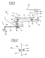
- FIG. 1 shows a tripod 100 designed as a ceiling stand, which is suspended by means of a stand column 101 with pivot 102 on a ceiling 103, for example in an operating room.
- a stand column 101 with pivot 102 on a ceiling 103
- this form as a floor stand.
- the column stand 101 is mounted with swivel 102 on a suitable stand base.
- the upright column 101 is connected to a first support arm 104 acting as a support arm, on which a second support arm 107 is received in an end region via a lifting arm support 105 with a pivot 106.
- This second carrier arm 107 acts as a lift arm.
- the support arm 104 can be pivoted on the stand column 101 due to the pivot joint 102 about an axis parallel to the stator column axis of rotation 110.
- the pivot 106 in the Hubarmango 105 ensures that the second support arm 107 is pivotable about an axis of rotation 111.
- the axis of rotation 111 in this case runs essentially parallel to the column stand 101 and lies in the exemplary embodiment explained with reference to FIG. 1 in the plane of the drawing. Under a substantially parallel course of axis of rotation 111 and column stator 101 is also understood a course that deviates, for example due to manufacturing tolerances of a strict parallel course.
- the second support arm 107 is pivotally mounted at a distance from the first support arm 104 to a pivot axis 112.
- This pivot axis extends on the one hand orthogonal to the axis of rotation 111 of the Hubarmangos 105 and is oriented in the figure perpendicular to the plane.
- This suspension of Hubarmanis 105 makes it possible, for example, the support arm 107 to move from a pivot position A in a direction indicated by dashed lines pivoting position A '.
- a counterweight 113 is provided in the stand 100.
- This counterweight 113 serves as a means for generating a restoring force.
- the counterweight 113 is arranged in the region of the column stand 101.
- the counterweight 113 is connected via a cable 114 as a means for coupling with a deflection roller 115, via which a torque is applied to the pivot axis 112, which compensates for the weight of the surgical microscope 109.
- This cable 114 thus couples the counterweight 113 with a movement of the second support arm 107 about the pivot axis 112.
- the cable 114 is guided by the guide roller 115 along the axis of rotation 111 of the swivel joint 106 in the Hubarmisme 105.
- a deflection roller 116 By means of a deflection roller 116, it is deflected toward the first carrier arm 104 and placed on a deflection roller 117, against which the counter-torque 113 caused by the counter-torque acts.
- the guide rollers 116 and 117 are mounted on axes of rotation 118, 119 which are oriented perpendicular to the first support arm 104 and the plane of the drawing.
- the counterweight 113 engages the deflection roller 117 with a lever arm 120.
- the counterweight 113 received on the lever arm 120 is moved from the position B to the position B' which is in FIG corresponding manner indicated by dashed lines.
- the resulting lever arms are different and adapted to the instantaneous position of the second support arm 108. This ensures that despite a changing load torque acting on the pivot axis 112, when the second support arm 107 is moved from the position A to the position A ', by means of the counterweight 113 a just required balancing force is generated.
- a freewheeling pivot 121 is provided in the cable 114 on the axis of rotation.
- This freewheeling pivot 121 causes the cable of the cable 114 to not twist when the second carrier arm 107 moves about the axis of rotation 111.
- the freewheel hinge 121 divides the cable 114 into a portion 122 associated with the second support arm 107 and a portion 123 facing the counterweight 113.
- a rotational movement of the second carrier arm 107 about the axis of rotation 111 does not lead to a feedback of this rotational movement in the cable pull section 123, on which the counterweight 113 is arranged.
- the counterweight 113, the inertia of the counterweight 113 is minimized upon rotation of the second support arm 107 about the axis of rotation 111 of the pivot joint 106 on Hubarmango.
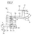
- FIG. 1 One possible embodiment for the freewheel hinge 120 of FIG. 1 is shown in FIG.
- This freewheel hinge is designed as a ball-bearing pivot joint 200.
- the section of the cable 201 facing the counterweight 113 from FIG. 1 is connected to a ball carrier plate 202.
- the pointing to the lifting arm 107 of Figure 1 section of the cable 205 is in turn fixed to a ball bearing housing 203.
- balls 204 are arranged. This construction makes it possible, upon rotation of the second carrier arm 107 of FIG. 1 about the axis of rotation 111 of FIG. 1, to freely rotate the ball bearing housing 203 together with the portion of the cable 205 facing the second carrier arm, without the portion of the cable which points towards the counterweight 113 201 to twist significantly.
- FIG. 3 shows, as a further embodiment of the invention, a stand 300 whose basic structure corresponds to that of the stand 100 from FIG.
- the tripod 300 is designed as a ceiling stand and suspended by means of a column stand 301 with swivel joint 302 on a ceiling 303, for example in an operating room. While maintaining the basic structure, however, it is also possible to carry the stand 300 as a floor stand, in which the stand column 301 is mounted with the hinge 302 on a stand base.
- first support arm 304 On the stand column 301 a acting as a support arm first support arm 304 is attached.
- This first support arm 304 is a Hubarmarme 305 associated with pivot 306, at a second support arm 307 is received.
- This second carrier arm 307 acts as a lifting arm. It is received on Hubarmarme 305 with a joint 308 and holds with a hinge 310 a surgical microscope 309 as a medical device.
- the first carrier arm 304 can be swiveled by means of a swivel joint 302 on the stand column 301 about a rotation axis 311 which is parallel to the stand column.
- the second support arm 307 is movable with the rotary joint 306 in the Hubarmarme 305 about the axis of rotation 312, which is substantially parallel to the stator column 301 and in the embodiment of Figure 3 is also in the drawing plane.
- the second support arm 307 is mounted on the Hubarmarme 305 with the hinge 308 on a pivot axis 313, which is oriented orthogonal to the axis of rotation 312 of the Hubarmitatis 305 and in the embodiment shown extends perpendicular to the plane.
- This arrangement of the pivot axis 313 makes it possible, for example, to move the support arm 307 in the case of the stand 300 from a pivot position A into a pivot position B indicated by dashed lines.
- a counterweight 314 is provided in the stand 300, which serves as a means for generating a restoring force.
- This counterweight 314 is arranged in the region of the column stand 301.
- the center of gravity of the overall system is also near the axis of rotation 311 of hinge 302 of the pedestal column 301 and the inertia effect of the counterweight 314 is minimized.
- the counterweight 314 is connected via a linkage assembly as a means for coupling with the second support arm 307.
- This linkage arrangement comprises a lever arm 315 which carries the counterweight 314 and which is mounted on an axis of rotation 316 oriented perpendicularly to the upright column 301 and to the first support arm 304.
- This lever arm 315 comprises a ball joint 317, which is located at the opposite. With respect to the rotation axis 316 to the counterweight 314 side.
- a transmission rod 318 is connected, which along the rotational axis 312 of the pivot 306 in the Hubarmisme 305 is guided.
- This transmission rod 318 is fixed to the second support arm 307 with a ball joint 319.
- a movement of the surgical microscope 309 from a pivot position A to a pivot position A ' is coupled to a corresponding movement of the counterweight 314 from a position B to a position B' indicated by dashed lines.
- a moment on the axis of rotation 313 of the second support arm 307, which causes a weight force acting on the surgical microscope 309, is thus counteracted by a moment generated by means of the counterweight 314.
- the ball joint 317 comprises a joint ball with a sleeve which receives the lever arm 315 freely displaceable.
- the ball joint 319 is formed on the second support arm 307.
- the transmission rod 318 is slidably guided along the rotational axis 312 between the rollers 320 and 321 and comprises a freewheeling rotary joint 322.
- the freewheeling rotary joint 322 may be formed in a manner corresponding to the freewheeling rotary joint 121 of FIG. It divides the transmission rod 318 into a portion 323 associated with the second support arm 307 and a portion 324 facing the counterweight 314.
- the freewheel hinge 322 causes the respective portions 323 and 324 of the transmission rod 318 to be freely rotatable relative to each other.
- a rotational movement of the second support arm 307 about the axis of rotation 312 of the Hubarmarmes 305 with the pivot 306 of a movement of the counterweight 314 is decoupled.
- a feedback of this rotational movement in the linkage assembly to the counterweight 314 is suppressed.
Description
Die Erfindung betrifft ein Stativ, insbesondere zur Aufnahme eines medizinischen Gerätes, beispielsweise eines Operationsmikroskops, mit einer Ständersäule, an der ein erster Trägerarm angeordnet ist und mit einem zweiten Trägerarm, der an dem ersten Trägerarm aufgenommen ist und relativ zu dem ersten Trägerarm um eine erste Achse und um eine von der ersten Achse verschiedenen zweiten Achse bewegt werden kann, bei dem zum Erzeugen einer Rückstellkraft für den zweiten Trägerarm um die erste Achse ein bewegbares Gewicht vorgesehen ist, und Mittel zum Koppeln vorgesehen sind, welche das Gewicht mit einer Bewegung des zweiten Trägerarmes um die erste Achse koppeln.The invention relates to a stand, in particular for receiving a medical device, for example a surgical microscope, with a column stand on which a first support arm is arranged and with a second support arm which is received on the first support arm and relative to the first support arm about a first Axis and about a second axis different from the first axis, wherein for generating a restoring force for the second support arm about the first axis, a movable weight is provided, and means are provided for coupling, which the weight with a movement of the second Couple low-arm around the first axis.
Ein derartiges Stativ ist aus der
Aus der
Die
In der
Aus der
Aufgabe der Erfindung ist es, ein Stativ bereitzustellen, das einerseits platzsparende Abmessungen aufweist, andererseits jedoch ermöglicht, daß ein schweres, am Stativ aufgenommenes medizinisches Gerät leicht in beliebige Richtungen bewegt werden kann.The object of the invention is to provide a tripod, on the one hand has space-saving dimensions, on the other hand, however, allows a heavy, recorded on the tripod medical device can be easily moved in any direction.
Diese Aufgabe wird durch ein Stativ mit den Merkmalen des Anspruchs 1 gelöst.This object is achieved by a tripod having the features of claim 1.
Bei einem Stativ gemäß Anspruch 1 ist das Gewicht im Bereich einer Ständersäule bewegbar angeordnet. Unter einem Gewicht, das im Bereich einer Ständersäule bewegbar angeordnet ist, wird dabei ein Gewicht verstanden, welches sich nahe bei bzw. in der Ständersäule befindet und dessen Position dort verändert werden kann. Indem es auf oder unmittelbar bei einer Drehachse der Ständersäule angeordnet ist, können Trägheitskräfte minimiert werden, die bei Drehung des Stativs um die Drehachse der Ständersäule auftreten. Diese Trägheitskräfte haben ihre Ursache in dem Gewicht und wirken der betreffenden Stativbewegung um die entsprechende Drehachse mit einem Gegenmoment entgegen. Eine solche Anordnung des Gewichts gewährleistet also eine leichte Drehbarkeit des Stativs um eine Achse der Ständersäule. Außerdem kann so ein kippstabiles Stativ mit niedrigem Geräteschwerpunkt geschaffen werden.In a tripod according to claim 1, the weight is arranged movably in the region of a column stand. Under a weight that is movably arranged in the region of a column stand, it is understood a weight which is close to or in the column stand and whose position can be changed there. By being disposed on or immediately adjacent an axis of rotation of the pedestal column, inertial forces which occur upon rotation of the pedestal about the axis of rotation of the pedestal column can be minimized. These inertial forces have their cause in the weight and counteract the relevant tripod movement about the corresponding axis of rotation with a counter-moment. Such an arrangement of the weight thus ensures easy rotation of the stand about an axis of the column stand. In addition, a tilt-stable tripod with low center of gravity can be created.
Das Gewicht bei dem erfindungsgemäßen Stativ wirkt als Gegengewicht. Auf diese Weise kann unter Beibehaltung einer einfachen Konstruktion durch Vergrößern oder Verkleinern des Gegengewichts eine Rückstellkraft für ein unterschiedliches Gewicht des von dem Stativ aufgenommenen medizinischen Geräts eingestellt werden.The weight in the tripod invention acts as a counterweight. In this way, while maintaining a simple construction by increasing or decreasing the counterweight, a restoring force for a different weight of the medical device accommodated by the stand can be adjusted.
In Weiterbildung der Erfindung sind die Mittel zum Koppeln als Seilzug ausgebildet. Auf diese Weise können die Mittel zum Koppeln leicht an eine gewünschte Stativgeometrie angepaßt werden.In a further development of the invention, the means for coupling are formed as a cable. In this way, the means for coupling can be easily adapted to a desired tripod geometry.
In Weiterbildung der Erfindung sind die Mittel zum Koppeln als Gestängeanordnung ausgebildet. Auf diese Weise wird ein Stativ geschaffen, das hohen mechanischen Belastungen standhält.In a further development of the invention, the means for coupling are designed as linkage arrangement. In this way, a tripod is created, which withstands high mechanical loads.
In Weiterbildung der Erfindung gleichen die Mittel zum Erzeugen einer Rückstellkraft eine an dem zweiten Arm angreifende Gewichtskraft aufgrund einer daran angeordneten Last aus. Auf diese Weise ist es möglich, das Stativ vollständig auszubalancieren, so daß das am Stativ aufgenommene medizinische Gerät nahezu kraftlos bewegt werden kann.In a further development of the invention, the means for generating a restoring force compensate for a force acting on the second arm weight force due to a load arranged thereon. In this way, it is possible to balance the tripod completely, so that the recorded on the tripod medical device can be moved almost powerless.
In Weiterbildung der Erfindung wird bei dem Stativ über den Seilzug eine ausgleichende Rückstellkraft übertragen, die an dem zweiten Arm in einem Abstand von der Ständersäule angreift, wobei der Seilzug in eine Parallelrichtung zur Ständersäule umgelenkt ist. Auf diese Weise kann ein Gegengewicht im Bereich der Ständersäule angeordnet werden, um so ein kippstabiles Stativ bereitzustellen, dessen Schwerpunkt im Bereich der Ständersäule liegt.In a further development of the invention, a compensating restoring force is transmitted to the tripod via the cable, which acts on the second arm at a distance from the pedestal column, wherein the cable is deflected in a direction parallel to the pedestal column. In this way, a counterweight in the area of the column stand can be arranged so as to provide a tilt-stable tripod whose center of gravity is in the area of the column stand.
Für den Seilzug kann eine Umlenkung zum Führen des Seilzugs in der Nähe einer Ständersäule vorgesehen werden. Auf diese Weise ist es möglich, in der Ständersäule ein Ausgleichsgewicht zu führen.For the cable, a deflection for guiding the cable near a column stand can be provided. In this way it is possible to guide a balance weight in the column stand.
In Weiterbildung der Erfindung ist beim Stativ der erste Trägerarm um eine zur Ständersäule im wesentlichen parallele Drehachse drehbar. Auf diese Weise wird ein Stativ mit großem Arbeitsbereich bereitgestellt.In a further development of the invention, the first support arm is rotatable about a pivot axis substantially parallel to the column stand in the tripod. In this way, a tripod with a large work area is provided.
Die Mittel zum Koppeln können wenigstens einmal unterbrochen sein. Auf diese Weise wird eine leichte Bewegbarkeit des Stativs gewährleistet. Insbesondere bei Verwendung eines Seilzuges als Mittel zum Koppeln oder einer Gestängeanordnung wird ein Verdrillen oder Verwinden von Seilzug bzw. Gestänge vermieden. Vorzugsweise ist den Mitteln zum Koppeln ein als Drehentkopplung wirkendes Freilaufdrehgelenk zugeordnet, welches ein Rückkoppeln einer Bewegung des zweiten Arms um wenigstens eine der beiden Achsen zu dem Mittel zum Erzeugen einer Rückstellkraft vermeidet. Auf diese Weise wird ein Stativ geschaffen, bei dem ein Rückstellmoment für eine Achse zum Ausgleich einer entsprechenden Stativbelastung keinerlei Auswirkungen auf die Bewegbarkeit des Stativs um eine andere Achse hervorruft.The means for coupling may be interrupted at least once. In this way, an easy mobility of the tripod is guaranteed. In particular, when using a cable as a means for coupling or a linkage arrangement twisting or twisting of cable or linkage is avoided. Preferably, the means for coupling is associated with acting as a rotational decoupling freewheel hinge, which avoids a feedback of a movement of the second arm about at least one of the two axes to the means for generating a restoring force. In this way, a tripod is created in which a restoring moment for an axle to compensate for a corresponding tripod load causes no effect on the mobility of the tripod about another axis.
Ein Freilaufdrehgelenk ermöglicht insbesondere das Verdrillen eines Seilzugs als Mittel zum Koppeln zu unterbinden.A freewheeling hinge in particular allows the twisting of a cable as a means of coupling to prevent.
In Weiterbildung der Erfindung ist die erste Achse im wesentlichen orthogonal zur zweiten Achse. Unter einer im wesentlichen orthogonalen Orientierung von erster und zweiter Achse wird eine Orientierung dieser Achsen verstanden, bei der diese innerhalb eines Toleranzintervalls um ± 20° senkrecht aufeinander stehen. Auf diese Weise wird ein Trägerarmsystem mit zwei Bewegungsfreiheitsgraden bereitgestellt, deren Gang von einem Benutzer des Stativs leicht erfaßt werden kann.In a further development of the invention, the first axis is substantially orthogonal to the second axis. A substantially orthogonal orientation of the first and second axes is understood to mean an orientation of these axes in which they are perpendicular to one another within a tolerance interval of ± 20 °. In this way, a carrier arm system having two degrees of freedom of movement is provided, the gear of which can be easily grasped by a user of the stand.
In Weiterbildung der Erfindung sind die erste und die zweite Achse in Abstand voneinander angeordnet. Auf diese Weise wird eine mechanisch einfache Bauform der Stativgelenke ermöglicht.In a further development of the invention, the first and the second axis are arranged at a distance from each other. In this way, a mechanically simple design of the tripod joints is possible.
In Weiterbildung der Erfindung liegt das Freilaufdrehgelenk auf einer der Achsen. Auf diese Weise kann als Freilaufdrehgelenk ein Wirbelblock verwendet werden, der die nahezu vollständige Unterdrückung einer Rückkopplung bewirkt.In a further development of the invention, the freewheel swivel joint is located on one of the axes. In this way can be used as a freewheeling hinge a swirl block, which causes the almost complete suppression of feedback.
In Weiterbildung der Erfindung ist der Seilzug wenigstens abschnittsweise über Rollen entlang einer der Achsen geführt. Auf diese Weise wird eine besonders reibungsarme Seilführung geschaffen.In development of the invention, the cable is at least partially guided over rollers along one of the axes. In this way, a particularly low-friction cable guide is created.
In Weiterbildung der Erfindung sind die Mittel zum Rückkoppeln als Gestänge ausgebildet, das eine entlang einer der Achsen verschiebbare Übertragungsstange umfaßt. Auf diese Weise ist es möglich, eine von einem Gegengewicht hervorgerufene Hebelwirkung als Rückstellkraft für ein am Stativ angeordnetes medizinisches Gerät auszunutzen.In a further development of the invention, the means for feedback are formed as a linkage comprising a displaceable along one of the axes transmission rod. In this way it is possible to exploit a lever action caused by a counterweight as a restoring force for a medical device arranged on the stand.
In Weiterbildung der Erfindung umfaßt das Stativ als Mittel zum Erzeugen einer Rückstellkraft einen Hebelarm, der an einem der Trägerarme angeordnet ist und ein Gegengewicht trägt, wobei die Mittel zum Koppeln eine Schwenkbewegung des Hebelarms an eine Schwenkbewegung des zweiten Trägerarms koppeln. Auf diese Weise ist es möglich. ein mit sich ändernder Stellung des medizinischen Geräts variierendes Lastmoment durch ein an das Lastmoment angepaßte Gegenmoment auszugleichen.In a further development of the invention, the stand as means for generating a restoring force comprises a lever arm which is arranged on one of the support arms and carries a counterweight, wherein the means for coupling couple a pivoting movement of the lever arm to a pivoting movement of the second support arm. This way it is possible. one compensate with changing position of the medical device varying load torque by a matched to the load torque counter torque.
In Weiterbildung der Erfindung ist das Stativ als Bodenstativ ausgebildet. Auf diese Weise wird ein leicht transportables Stativ bereitgestellt.In a further development of the invention, the tripod is designed as a floor stand. This provides an easily transportable tripod.
Wird das Stativ mit dieser Bauform als Deckenstativ ausgebildet, so wird ein besonders platzsparender Stativaufbau geschaffen.If the tripod with this design is designed as a ceiling stand, a particularly space-saving stand construction is created.
Weitere Merkmale und Vorteile der Erfindung sind in den Zeichnungen dargestellt und werden nachfolgend beschrieben.Further features and advantages of the invention are illustrated in the drawings and will be described below.
Es zeigen:
- Figur 1:
- eine erste Ausführungsform eines Stativs;
- Figur 2:
- den Aufbau eines Freilaufdrehgelenks in einem Stativ aus Figur 1; und
- Figur 3:
- eine zweite Ausführungsform eines Stativs.
- FIG. 1:
- a first embodiment of a tripod;
- FIG. 2:
- the structure of a freewheel hinge in a tripod of Figure 1; and
- FIG. 3:
- a second embodiment of a tripod.
Die Figur 1 zeigt ein als Deckenstativ ausgebildetes Stativ 100, welches mittels einer Ständersäule 101 mit Drehgelenk 102 an einer Decke 103, beispielsweise in einem Operationssaal aufgehängt ist. In Alternative zur Ausführung des Stativs 100 als Deckenstativ ist es auch möglich, unter Beibehaltung des wesentlichen Konstruktionsprinzips, dieses als Bodenstativ auszubilden. In diesem Fall wird beispielsweise die Ständersäule 101 mit Drehgelenk 102 auf einen geeigneten Stativfuß montiert.FIG. 1 shows a
Die Ständersäule 101 ist mit einem als Tragarm wirkenden ersten Trägerarm 104 verbunden, an dem in einem Endbereich über einen Hubarmträger 105 mit Drehgelenk 106 ein zweiter Trägerarm 107 aufgenommen ist. Dieser zweite Trägerarm 107 wirkt als Hubarm.The
Er hat in einem Endbereich ein Gelenk 108, an dem ein Operationsmikroskop 109 als medizinisches Gerät gelagert ist.It has in one end region a joint 108 on which a
Der Trägerarm 104 kann aufgrund des Drehgelenks 102 an der Ständersäule 101 um eine zur Ständersäule parallele Drehachse 110 geschwenkt werden. Das Drehgelenk 106 im Hubarmträger 105 gewährleistet, dass der zweite Trägerarm 107 um eine Drehachse 111 schwenkbar ist. Die Drehachse 111 verläuft dabei im wesentlichen parallel zur Ständersäule 101 und liegt beim anhand von Figur 1 erläuterten Ausführungsbeispiel in der Zeichenebene. Unter einem im wesentlichen parallelen Verlauf von Drehachse 111 und Ständersäule 101 wird dabei auch ein Verlauf verstanden, der beispielsweise bedingt durch Fertigungstoleranzen von einem strengen parallelen Verlauf abweicht.The
Am Hubarmträger 105 ist der zweite Trägerarm 107 in Abstand vom ersten Trägerarm 104 an einer Schwenkachse 112 schwenkbeweglich gelagert. Diese Schwenkachse verläuft einerseits orthogonal zur Drehachse 111 des Hubarmträgers 105 und ist in der Figur senkrecht zur Zeichenebene orientiert. Diese Aufhängung des Hubarmträgers 105 ermöglicht es, beispielsweise den Trägerarm 107 aus einer Schwenkposition A in eine mittels gestrichelten Linien angedeutete Schwenkposition A' zu bewegen.On
Um eine an dem Operationsmikroskop 109 angreifende Gewichtskraft auszugleichen, die an der Schwenkachse 112 einen Moment hervorruft, welches bestrebt ist, das Operationsmikroskop 109 abzusenken, ist bei dem Stativ 100 ein Gegengewicht 113 vorgesehen. Dieses Gegengewicht 113 dient als Mittel zum Erzeugen einer Rückstellkraft. Das Gegengewicht 113 ist im Bereich der Ständersäule 101 angeordnet. Damit wird eine Trägheitswirkung des Gegengewichts 113 bei einer Bewegung der Ständersäule 101 mit den Trägerarmen 104 und 107 um die Drehachse 110 minimiert, bei der das Gegengewicht ein unerwünschtes Gegenmoment hervorruft und somit die Bewegung um die Drehachse 110 erschweren würde. Ferner liegt so der Gesamtschwerpunkt des Stativs bei aufgenommenem Operationsmikroskop im Bereich der Ständersäule 101 in der Nähe der Drehachse 110 und es werden beim Drehgelenk 102 solche Lagerkräfte minimiert, die senkrecht zu dessen Drehachse 110 orientiert sind.In order to compensate for a force acting on the
Das Gegengewicht 113 ist über einen Seilzug 114 als Mittel zum Koppeln mit einer Umlenkrolle 115 verbunden, über die ein Moment auf die Schwenkachse 112 aufgebracht wird, das die Gewichtskraft des Operationsmikroskops 109 ausgleicht. Dieser Seilzug 114 koppelt somit das Gegengewicht 113 mit einer Bewegung des zweiten Trägerarms 107 um die Schwenkachse 112. Der Seilzug 114 wird von der Umlenkrolle 115 entlang der Drehachse 111 des Drehgelenks 106 in dem Hubarmträger 105 geführt. Mittels einer Umlenkrolle 116 wird es zum ersten Trägerarm 104 hin umgelenkt und auf eine Umlenkrolle 117 gelegt, an der das von dem Gegengewicht 113 hervorgerufene Gegenmoment angreift. Bei dem in der Figur 1 gezeigten Ausführungsbeispiel sind die Umlenkrollen 116 und 117 auf Drehachsen 118, 119 gelagert, die jeweils zum ersten Trägerarm 104 und zur Zeichenebene senkrecht orientiert sind. Das Gegengewicht 113 greift an der Umlenkrolle 117 mit einem Hebelarm 120 an. Bei Bewegung des zweiten Trägerarmes 107 mit einem an ihm aufgenommenen Operationsmikroskop 109 aus einer ersten Schwenkposition A in die zweite mit gestrichelten Linien angedeutete Schwenkposition A' wird das an dem Hebelarm 120 aufgenommene Gegengewicht 113 aus der Stellung B in die Stellung B' bewegt, die in entsprechender Weise mit gestrichelten Linien angedeutet ist. In den jeweiligen Stellungen des Gegengewichts 113 sind die resultierenden Hebelarme unterschiedlich und an die momentane Stellung des zweiten Trägerarmes 108 angepasst. Dies gewährleistet, dass trotz eines sich ändernden Lastmoments, das an der Schwenkachse 112 angreift, wenn der zweite Trägerarm 107 aus der Position A in die Position A' bewegt wird, mittels des Gegengewichts 113 eine gerade benötigte Ausgleichskraft erzeugt wird.The
Im Bereich des Hubarmträgers 105 ist im Seilzug 114 auf der Drehachse 111 ein Freilaufdrehgelenk 121 vorgesehen. Dieses Freilaufdrehgelenk 121 bewirkt, dass sich bei einer Bewegung des zweiten Trägerarmes 107 um die Drehachse 111 das Seil des Seilzuges 114 nicht verdrillt. Außerdem unterteilt das Freilaufdrehgelenk 121 den Seilzug 114 in einen dem zweiten Trägerarm 107 zugeordneten Abschnitt 122 und einen Abschnitt 123, der zum Gegengewicht 113 weist. Diese betreffenden Abschnitte 122 und 123 des Seilzugs 114 sind somit zueinander frei drehbar, so dass eine Drehbewegung des zweiten Trägerarmes 107 um die Drehachse 111 von einer Bewegung des Gegengewichts 113 völlig entkoppelt ist.In the region of the
Insbesondere führt eine Drehbewegung des zweiten Trägerarmes 107 um die Drehachse 111 nicht zu einer Rückkopplung dieser Drehbewegung in den Seilzugabschnitt 123, an dem das Gegengewicht 113 angeordnet ist. Außerdem wird bei dieser Anordnung des Gegengewichts 113 die Trägheit des Gegengewichts 113 bei einer Drehung des zweiten Trägerarmes 107 um die Drehachse 111 des Drehgelenks 106 am Hubarmträger minimiert.In particular, a rotational movement of the
Eine mögliche Ausführungsform für das Freilaufdrehgelenk 120 aus Figur 1 ist in der Figur 2 gezeigt. Dieses Freilaufdrehgelenk ist als kugelgelagertes Drehgelenk 200 ausgebildet. Der zum Gegengewicht 113 aus Figur 1 weisende Abschnitt des Seilzuges 201 ist mit einer Kugelträgerplatte 202 verbunden. Der zum Hubarm 107 aus Figur 1 weisende Abschnitt des Seilzuges 205 ist wiederum an einem Kugellagergehäuse 203 festgelegt. Zwischen der Kugelträgerplatte 202 und dem Kugellagergehäuse 203 sind Kugeln 204 angeordnet. Dieser Aufbau ermöglicht, dass sich bei einer Drehung des zweiten Trägerarmes 107 aus Figur 1 um die Drehachse 111 aus Figur 1 das Kugellagergehäuse 203 zusammen mit dem zum zweiten Trägerarm weisenden Abschnitt des Seilzuges 205 frei drehen kann, ohne den zum Gegengewicht 113 weisenden Abschnitt des Seilzuges 201 nennenswert zu verdrillen.One possible embodiment for the
Anstatt das Freilaufdrehgelenk wie anhand der Figur 2 erläutert als kugelgelagertes Drehgelenk auszubilden, ist es auch möglich, dieses als Wirbelblock oder in einer anderen bekannten Weise auszuführen.Instead of the freewheeling hinge as illustrated with reference to Figure 2 as a ball-bearing pivot, it is also possible to perform this as a vortex block or in another known manner.
Die Figur 3 zeigt als weitere Ausführungsform der Erfindung ein Stativ 300, dessen grundsätzlicher Aufbau demjenigen des Stativs 100 aus Figur 1 entspricht. Wie das Stativ 100 aus Figur 1 ist das Stativ 300 als Deckenstativ ausgebildet und mittels einer Ständersäule 301 mit Drehgelenk 302 an einer Decke 303 beispielsweise in einem Operationssaal aufgehängt. Unter Beibehaltung des grundsätzlichen Aufbaus ist es jedoch auch möglich, das Stativ 300 als Bodenstativ auszuführen, bei dem die Ständersäule 301 mit dem Drehgelenk 302 auf einen Stativfuß montiert ist.FIG. 3 shows, as a further embodiment of the invention, a
An der Ständersäule 301 ist ein als Tragarm wirkender erster Trägerarm 304 befestigt. Diesem ersten Trägerarm 304 ist ein Hubarmträger 305 mit Drehgelenk 306 zugeordnet, an dem ein zweiter Trägerarm 307 aufgenommen ist. Dieser zweite Trägerarm 307 wirkt als Hubarm. Er ist am Hubarmträger 305 mit einem Gelenk 308 aufgenommen und hält mit einer Gelenkverbindung 310 ein Operationsmikroskop 309 als medizinisches Gerät.On the stand column 301 a acting as a support arm
Entsprechend dem Stativ 100 aus Figur 1 kann der erste Trägerarm 304 mittels Drehgelenk 302 an der Ständersäule 301 um eine zur Ständersäule parallele Drehachse 311 geschwenkt werden. Der zweite Trägerarm 307 ist mit dem Drehgelenk 306 im Hubarmträger 305 um die Drehachse 312 bewegbar, die im wesentlichen parallel zur Ständersäule 301 verläuft und beim Ausführungsbeispiel der Figur 3 ebenfalls in der Zeichenebene liegt. Der zweite Trägerarm 307 ist am Hubarmträger 305 mit dem Gelenk 308 an einer Schwenkachse 313 gelagert, die orthogonal zur Drehachse 312 des Hubarmträgers 305 orientiert ist und im gezeigten Ausführungsbeispiel senkrecht zur Zeichenebene verläuft. Diese Anordnung der Schwenkachse 313 ermöglicht es, beispielsweise den Trägerarm 307 beim Stativ 300 aus einer Schwenkposition A in eine mit gestrichelten Linien angedeutete Schwenkposition B zu bewegen.According to the stand 100 from FIG. 1, the
Um eine durch die am Operationsmikroskop 309 angreifende Gewichtskraft auszugleichen, die an der Schwenkachse 313 ein entsprechendes Lastmoment hervorruft, ist beim Stativ 300 ein Gegengewicht 314 vorgesehen, das als Mittel zum Erzeugen einer Rückstellkraft dient. Dieses Gegengewicht 314 ist im Bereich der Ständersäule 301 angeordnet. Somit liegt auch der Massenschwerpunkt des Gesamtsystems in der Nähe der Drehachse 311 von Drehgelenk 302 der Ständersäule 301 und die Trägheitswirkung des Gegengewichts 314 wird minimiert.In order to compensate for a force acting on the
Das Gegengewicht 314 ist über eine Gestängeanordnung als Mittel zum Koppeln mit dem zweiten Tragarm 307 verbunden. Diese Gestängeanordnung umfasst einen das Gegengewicht 314 tragenden Hebelarm 315, der an einer senkrecht zur Ständersäule 301 und zum ersten Tragarm 304 orientierten Drehachse 316 gelagert ist. Dieser Hebelarm 315 umfasst ein Kugelgelenk 317, welches an der bzgl. der Drehachse 316 zum Gegengewicht 314 gegenüberliegenden Seite befindet. An diesem Kugelgelenk 317 ist eine Übertragungsstange 318 angeschlossen, die entlang der Drehachse 312 des Drehgelenks 306 in dem Hubarmträger 305 geführt ist. Diese Übertragungsstange 318 ist mit einem Kugelgelenk 319 an dem zweiten Trägerarm 307 befestigt. Somit ist eine Bewegung des Operationsmikroskopes 309 aus einer Schwenkposition A in eine Schwenkposition Stellung A' mit einer entsprechenden Bewegung des Gegengewichtes 314 aus einer Stellung B in ein mit gestrichelten Linien angedeutete Stellung B' gekoppelt. Einem Moment an der Drehachse 313 des zweiten Trägerarms 307, das eine Gewichtskraft hervorruft, die am Operationsmikroskop 309 angreift, wird somit durch ein mittels des Gegengewichts 314 erzeugtes Moment entgegengewirkt.The
Das Kugelgelenk 317 umfasst eine Gelenkkugel mit einer Hülse, die den Hebelarm 315 frei verschiebbar aufnimmt. In entsprechender Weise ist das Kugelgelenk 319 am zweiten Trägerarm 307 ausgebildet. Die Übertragungsstange 318 ist entlang der Drehachse 312 zwischen den Rollen 320 und 321 verschiebbar geführt und umfasst ein Freilaufdrehgelenk 322. Das Freilaufdrehgelenk 322 kann in entsprechender Weise zum Freilaufdrehgelenk 121 aus Figur 1 ausgebildet sein. Es unterteilt die Übertragungsstange 318 in einen Abschnitt 323, der dem zweiten Trägerarm 307 zugeordnet ist und einen Abschnitt 324, der zum Gegengewicht 314 weist.The ball joint 317 comprises a joint ball with a sleeve which receives the
Das Freilaufdrehgelenk 322 bewirkt, dass die betreffenden Abschnitte 323 und 324 der Übertragungsstange 318 frei zueinander drehbar sind. Somit ist eine Drehbewegung des zweiten Trägerarmes 307 um die Drehachse 312 des Hubarmträgers 305 mit dem Drehgelenk 306 von einer Bewegung des Gegengewichtes 314 entkoppelt. Insbesondere wird somit eine Rückkopplung dieser Drehbewegung in die Gestängeanordnung zum Gegengewicht 314 unterdrückt.The
Claims (18)
- Support (100, 300), in particular for receiving a medical appliance, for example an operation microscope (109, 309),- with a support column (101, 301), on which a first carrier arm (104, 304) is arranged, and- with a second carrier arm (107, 307) which is mounted on the first carrier arm (104, 304) and can be moved relative to said first carrier arm (104, 304) about a first axis (112, 313) and about a second axis (111, 312) different from the first axis,- a movable weight (113, 314) being provided for producing a restoring force for the second carrier arm (107, 307) about the first axis (112, 313), and- coupling means (114, 315 - 319) being provided which couple the weight (113, 314) to a movement of the second carrier arm (107, 30 7) about the first axis (112, 313),characterized in that
the movable weight (113, 314) is arranged in the area of the support column (101, 301). - Support according to Claim 1, characterized in that a cable (114) is provided for coupling the weight (113) and the second carrier arm (107).
- Support according to Claim 2, characterized in that a deflecting means (1 16) is provided for guiding the cable (114).
- Support according to Claim 2 or 3, characterized in that the cable (114) is guided at least in some sections via rollers (115, 116) along one of the axes (111).
- Support according to one of Claims 2 to 4, characterized in that a compensating restoring force is transmitted via the cable (114) and impinges on the second carrier arm (107) at a distance from a support column (101), the cable (114) being deflected into a parallel direction to the support column (101).
- Support according to Claim 1, characterized in that a rod arrangement (315 - 319) is provided for coupling the weight (314) and the carrier arm (307).
- Support according to Claim 6, characterized in that the rod arrangement comprises a transmission rod (318) displaceable along one of the axes.
- Support according to one of Claims 1 to 7, characterized in that the first carrier arm (104, 304) is arranged on a support column (101, 301) and can be turned about an axis (110, 311) of the support column (101, 301), the weight (113, 314) being movable in the area of the support column (101, 301).
- Support according to one of Claims 1 to 8, characterized in that the weight (113, 314) compensates for a weight force impinging on the second arm (107, 307) because of a load (109, 309) arranged on it.
- Support according to one of Claims 1 to 9, characterized in that the first carrier arm (104, 304) can turn about a rotation axis (110, 311) substantially parallel to the support column (101, 301) .
- Support according to one of Claims 1 to 10, characterized in that the coupling means (114, 315 - 319), in order to suppress a feedback coupling of a movement of the second carrier arm (107, 307) about the second axis (111, 312) to the weight, have a freewheel rotary joint (121, 322) acting as rotation decoupler.
- Support according to Claim 11, characterized in that the freewheel rotary joint (121, 322) lies on one of the axes (111, 312).
- Support according to either of Claims 1 1 and 12, characterized in that the freewheel rotary joint (121, 322) is designed as a ball-bearing rotary joint (200) or as a swivel block.
- Support according to one of Claims 1 to 13, characterized in that the first axis (112, 313) is substantially orthogonal to the second axis (111, 312).
- Support according to one of Claims 1 to 14, characterized in that the first axis (112, 313) and the second axis (111, 312) are arranged at a distance from one another.
- Support according to one of Claims 1 to 15, characterized in that the movable weight (113, 314) is assigned a lever arm (120, 315) which is arranged on one of the carrier arms (104, 304) and bears the weight (113, 314), and the coupling means (114, 315 - 319) couple a pivoting movement of the lever arm (120, 315) to a pivoting movement of the second carrier arm (107, 307).
- Support according to one of Clai ms 1 to 16, characterized in that the support is designed as a floor support stand.
- Support according to one of Claims 1 to 17, characterized in that the support is designed as a ceiling support (100, 300).
Applications Claiming Priority (3)
| Application Number | Priority Date | Filing Date | Title |
|---|---|---|---|
| DE10048545 | 2000-09-30 | ||
| DE10048545 | 2000-09-30 | ||
| EP01120922A EP1193439B1 (en) | 2000-09-30 | 2001-08-31 | Stand |
Related Parent Applications (2)
| Application Number | Title | Priority Date | Filing Date |
|---|---|---|---|
| EP01120922.8 Division | 2001-08-31 | ||
| EP01120922A Division EP1193439B1 (en) | 2000-09-30 | 2001-08-31 | Stand |
Publications (4)
| Publication Number | Publication Date |
|---|---|
| EP1538386A2 EP1538386A2 (en) | 2005-06-08 |
| EP1538386A3 EP1538386A3 (en) | 2006-05-24 |
| EP1538386B1 true EP1538386B1 (en) | 2007-08-08 |
| EP1538386B2 EP1538386B2 (en) | 2010-11-03 |
Family
ID=7658259
Family Applications (2)
| Application Number | Title | Priority Date | Filing Date |
|---|---|---|---|
| EP05000973A Expired - Lifetime EP1538386B2 (en) | 2000-09-30 | 2001-08-31 | Stand |
| EP01120922A Expired - Lifetime EP1193439B1 (en) | 2000-09-30 | 2001-08-31 | Stand |
Family Applications After (1)
| Application Number | Title | Priority Date | Filing Date |
|---|---|---|---|
| EP01120922A Expired - Lifetime EP1193439B1 (en) | 2000-09-30 | 2001-08-31 | Stand |
Country Status (5)
| Country | Link |
|---|---|
| US (2) | US7416163B2 (en) |
| EP (2) | EP1538386B2 (en) |
| JP (1) | JP4102046B2 (en) |
| AT (3) | ATE369520T1 (en) |
| DE (4) | DE20114343U1 (en) |
Families Citing this family (28)
| Publication number | Priority date | Publication date | Assignee | Title |
|---|---|---|---|---|
| JP4222706B2 (en) * | 2000-03-22 | 2009-02-12 | オリンパス株式会社 | Medical instrument holding device |
| DE20114343U1 (en) | 2000-09-30 | 2001-11-29 | Zeiss Carl | tripod |
| DE20019105U1 (en) * | 2000-11-12 | 2001-05-23 | Leica Microsystems | tripod |
| DE10116495C1 (en) * | 2001-04-03 | 2002-10-17 | Draeger Medical Ag | Ceiling stand for a medical lamp |
| US7410138B2 (en) * | 2003-03-14 | 2008-08-12 | Tgr Intellectual Properties, Llc | Display adjustably positionable about swivel and pivot axes |
| EP1746331A1 (en) * | 2005-07-18 | 2007-01-24 | Max Wang | Support device for a display |
| GB2437052A (en) * | 2006-04-13 | 2007-10-17 | Colebrook Bosson Saunders Prod | Monitor support arm |
| DE112007003460B4 (en) * | 2007-04-20 | 2013-11-07 | Carl Zeiss Meditec Ag | Holding device for medical-optical equipment, in particular for monitor |
| DE102008015210A1 (en) * | 2008-03-20 | 2009-09-24 | Maquet Gmbh & Co. Kg | Tripod for holding and positioning a payload in the room |
| JP5135069B2 (en) | 2008-06-12 | 2013-01-30 | 三鷹光器株式会社 | Medical instrument holding arm device |
| CN103097978B (en) * | 2010-07-08 | 2016-08-10 | 索斯科公司 | Supporter for display device |
| US8960632B2 (en) | 2011-07-05 | 2015-02-24 | Mediamounts, Ltd. | Dual bar linkage monitor support with adustment feature |
| US10695250B2 (en) * | 2012-07-24 | 2020-06-30 | Maquet (Suzhou) Co., Ltd. | Medical supply unit having an elbow joint part |
| US9243743B2 (en) | 2013-03-01 | 2016-01-26 | Icwusa.Com, Inc. | Support arm |
| WO2016160272A1 (en) | 2015-03-27 | 2016-10-06 | Sonitrack Systems, Inc. | Rapidly repositionable powered support arm |
| US11131423B2 (en) | 2016-03-07 | 2021-09-28 | Southco, Inc. | Display support arm assembly for mounting a display |
| EP3275394B1 (en) | 2016-07-26 | 2019-03-27 | Ondal Medical Systems GmbH | Supporting arm system |
| US10845000B2 (en) | 2016-10-21 | 2020-11-24 | Colebrook Bosson Saunders (Products) Limited | Display support system |
| EP3638941B1 (en) * | 2017-06-13 | 2023-12-27 | In2Ergo, Inc. | Monitor and keyboard support arm |
| US10987175B2 (en) | 2017-12-06 | 2021-04-27 | Medtech S.A. | Robotic shoulder repair and reconstruction |
| EP3518014B1 (en) * | 2018-01-30 | 2020-11-18 | Leica Instruments (Singapore) Pte. Ltd. | Balancing device and method for balancing a microscope |
| US10772704B2 (en) | 2018-03-12 | 2020-09-15 | Zimmer Biomet CMF and Thoracic, LLC | End effector coupler for surgical arm |
| US10687792B2 (en) | 2018-03-12 | 2020-06-23 | Zimmer Biomet CMF and Thoracic, LLC | End effector coupler for surgical arm |
| USD878585S1 (en) | 2018-03-12 | 2020-03-17 | Zimmer Biomet CMF and Thoracic, LLC | End effector coupler stem |
| US10835345B2 (en) | 2018-03-12 | 2020-11-17 | Zimmer Biomet CMF and Thoracic, LLC | End effector coupler for surgical arm |
| US11224495B2 (en) * | 2019-06-07 | 2022-01-18 | Welch Allyn, Inc. | Medical device support system |
| WO2023030382A1 (en) * | 2021-09-06 | 2023-03-09 | 南京迈瑞生物医疗电子有限公司 | Medical boom and medical boom system |
| DE202022100487U1 (en) | 2022-01-28 | 2023-05-05 | Rollax Gmbh & Co. Kg | tripod head |
Citations (1)
| Publication number | Priority date | Publication date | Assignee | Title |
|---|---|---|---|---|
| EP0628290A1 (en) * | 1992-12-28 | 1994-12-14 | Mitaka Kohki Co., Ltd. | Stand device of optical instrument for medical use |
Family Cites Families (36)
| Publication number | Priority date | Publication date | Assignee | Title |
|---|---|---|---|---|
| US3210114A (en) * | 1963-11-21 | 1965-10-05 | Lawton Lawrence | Apparatus for orienting a suspended load |
| US3396931A (en) † | 1965-07-21 | 1968-08-13 | Emil L. Eckstein | Weight-balanced adjustable radiation apparatus |
| US3891301A (en) * | 1972-08-18 | 1975-06-24 | Contraves Ag | Adjustable support or stand for an optical observation instrument |
| DE2311257A1 (en) † | 1973-03-07 | 1974-09-12 | Moeller J D Optik | MICROSURGICAL UNIT |
| NL7809850A (en) | 1978-09-29 | 1980-04-01 | Philips Nv | DEVICE WITH A BALANCED SWIVEL ARM. |
| JPS607489B2 (en) * | 1979-07-18 | 1985-02-25 | 旭光学工業株式会社 | Counterbalance mechanism of laser scalpel device |
| DE7930125U1 (en) † | 1979-07-24 | 1980-01-24 | Contraves Ag, Zuerich (Schweiz) | ADDITIONAL DEVICE ON A TRIPOD FOR AN OPTICAL OBSERVATION DEVICE |
| DE7930126U1 (en) * | 1979-07-24 | 1980-01-24 | Contraves Ag, Zuerich (Schweiz) | TRIPOD FOR AN OPTICAL OBSERVATION DEVICE |
| US4266747A (en) | 1979-07-26 | 1981-05-12 | Positioning Devices, Incorporated | Equipoised articulated support arm |
| GB2074337B (en) | 1980-04-15 | 1983-11-16 | Univ Technology | Adjustable support for an optical or other instrument |
| EP0048404B1 (en) † | 1980-09-18 | 1986-02-05 | Firma Carl Zeiss | Adjustable stand for optical observing units |
| US4548373A (en) * | 1983-03-22 | 1985-10-22 | Tokyo Kogaku Kikai Kabushiki Kaisha | Medical equipment supporting device |
| US4741607A (en) † | 1986-03-17 | 1988-05-03 | Contraves Ag | Supporting device for an optical observation instrument |
| JPH02503519A (en) * | 1987-05-27 | 1990-10-25 | サージカル ナビゲーション テクノロジース インコーポレーティッド(アン アフィリエイティッド カンパニー オブ ソファマー ダンネク グループ インコーポレーティッド) | Method and apparatus for reproducibly optically displaying surgical procedures |
| JPS63296743A (en) * | 1987-05-29 | 1988-12-02 | Mitaka Koki Kk | Stand apparatus for medical optical machinery |
| IT1230057B (en) | 1989-04-13 | 1991-09-27 | Zambon Spa | INTERMEDIATE RESOLUTION PROCESS USEFUL FOR THE PREPARATION OF 1,5-BENZOTHIAZEPINE |
| US5273039A (en) * | 1989-10-16 | 1993-12-28 | Olympus Optical Co., Ltd. | Surgical microscope apparatus having a function to display coordinates of observation point |
| DE3937631A1 (en) | 1989-11-11 | 1991-05-16 | Saar Gmbh Drahtseilwerk | SWIVEL FOR FASTENING THE FIXED END OF AT LEAST ONE CRANE ROPE LOSELY ROLLING HOLDING THE LOAD RECEIVER |
| JPH0413591A (en) † | 1990-04-27 | 1992-01-17 | Mitsubishi Electric Corp | Industrial robot |
| DE9013260U1 (en) * | 1990-09-19 | 1990-11-22 | Fa. Carl Zeiss, 7920 Heidenheim, De | |
| JPH066136B2 (en) * | 1991-12-25 | 1994-01-26 | 佐原 今朝徳 | Stand equipment for medical optical equipment |
| DE4202922A1 (en) * | 1992-02-01 | 1993-08-05 | Zeiss Carl Fa | MOTORIC TRIPOD |
| US5435515A (en) * | 1992-09-15 | 1995-07-25 | Garrett W. Brown | Adustable, iso-elastic support apparatus |
| JPH0773587B2 (en) * | 1993-03-18 | 1995-08-09 | 三鷹光器株式会社 | Biaxial balance adjustment structure for medical stand device |
| WO1994028815A1 (en) * | 1993-06-15 | 1994-12-22 | Mitaka Kohki Co., Ltd. | Stand for optical device |
| DE4334069A1 (en) * | 1993-06-21 | 1995-04-13 | Zeiss Carl Fa | Balanced tripod |
| DE4320443C2 (en) † | 1993-06-21 | 2001-08-02 | Zeiss Carl | Balanced tripod |
| US5609316A (en) * | 1995-09-05 | 1997-03-11 | Tigliev; George S. | Suspension system for surgical microscope |
| DE59610558D1 (en) | 1995-10-12 | 2003-07-31 | Leica Ag Heerbrugg | TRIPOD |
| US5690316A (en) * | 1996-08-06 | 1997-11-25 | Madjarac; John | Timber wedge |
| US5818638A (en) * | 1996-11-27 | 1998-10-06 | Mitaka Kohki Co. Ltd. | Deflection compensating structure for medical stand apparatus |
| DE19742050B4 (en) † | 1997-09-24 | 2008-07-31 | Carl Zeiss | Tripod with weight compensation |
| DE19820710A1 (en) * | 1998-05-11 | 1999-11-18 | Kai Trebesius | Stand with unbalanced lever arm for e.g. lamps |
| DE20114343U1 (en) * | 2000-09-30 | 2001-11-29 | Zeiss Carl | tripod |
| DE20019105U1 (en) | 2000-11-12 | 2001-05-23 | Leica Microsystems | tripod |
| DE20019107U1 (en) † | 2000-11-12 | 2001-01-25 | Leica Microsystems | tripod |
-
2001
- 2001-08-30 DE DE20114343U patent/DE20114343U1/en not_active Expired - Lifetime
- 2001-08-30 DE DE10142564A patent/DE10142564A1/en not_active Ceased
- 2001-08-31 EP EP05000973A patent/EP1538386B2/en not_active Expired - Lifetime
- 2001-08-31 EP EP01120922A patent/EP1193439B1/en not_active Expired - Lifetime
- 2001-08-31 AT AT05000973T patent/ATE369520T1/en active
- 2001-08-31 DE DE50106184T patent/DE50106184D1/en not_active Expired - Lifetime
- 2001-08-31 DE DE50112848T patent/DE50112848D1/en not_active Expired - Lifetime
- 2001-08-31 AT AT01120922T patent/ATE295503T1/en active
- 2001-09-28 US US09/967,769 patent/US7416163B2/en not_active Expired - Lifetime
- 2001-09-28 AT AT0074701U patent/AT5964U1/en not_active IP Right Cessation
- 2001-10-01 JP JP2001304893A patent/JP4102046B2/en not_active Expired - Lifetime
-
2007
- 2007-04-07 US US11/784,701 patent/US7665702B2/en not_active Expired - Fee Related
Patent Citations (1)
| Publication number | Priority date | Publication date | Assignee | Title |
|---|---|---|---|---|
| EP0628290A1 (en) * | 1992-12-28 | 1994-12-14 | Mitaka Kohki Co., Ltd. | Stand device of optical instrument for medical use |
Also Published As
| Publication number | Publication date |
|---|---|
| JP4102046B2 (en) | 2008-06-18 |
| EP1538386A2 (en) | 2005-06-08 |
| AT5964U1 (en) | 2003-02-25 |
| US20020074472A1 (en) | 2002-06-20 |
| EP1193439A2 (en) | 2002-04-03 |
| US7416163B2 (en) | 2008-08-26 |
| DE50112848D1 (en) | 2007-09-20 |
| ATE369520T1 (en) | 2007-08-15 |
| JP2002153488A (en) | 2002-05-28 |
| EP1193439B1 (en) | 2005-05-11 |
| DE10142564A1 (en) | 2002-04-11 |
| ATE295503T1 (en) | 2005-05-15 |
| EP1538386A3 (en) | 2006-05-24 |
| DE50106184D1 (en) | 2005-06-16 |
| EP1193439A3 (en) | 2003-10-08 |
| EP1538386B2 (en) | 2010-11-03 |
| US7665702B2 (en) | 2010-02-23 |
| DE20114343U1 (en) | 2001-11-29 |
| US20070187562A1 (en) | 2007-08-16 |
Similar Documents
| Publication | Publication Date | Title |
|---|---|---|
| EP1538386B1 (en) | Stand | |
| DE4333207C3 (en) | Industrial robots | |
| EP0866260B1 (en) | Supporting device | |
| EP1207334B1 (en) | Stand | |
| EP1223004B1 (en) | Machine tool with control board | |
| EP0202399B1 (en) | Stand for an optical observation apparatus | |
| EP2103861A2 (en) | Support for holding and positioning a payload in a room | |
| WO1991000472A1 (en) | Stand equipped with accessory devices, for supporting freely orientable apparatus | |
| DE202008017923U1 (en) | Operating light with suspension device | |
| DE19742050A1 (en) | Stand for movable appliance, e.g. operational microscope | |
| DE19742051B4 (en) | Tripod with energy storage for weight balance | |
| WO2020035612A1 (en) | Device for supporting a monitor | |
| EP0496994B1 (en) | Support | |
| DE112007003460B4 (en) | Holding device for medical-optical equipment, in particular for monitor | |
| CH692926A5 (en) | Tripod with energy storage to balance the weight. | |
| DE19945189B4 (en) | hoist | |
| EP0749810A1 (en) | Robot | |
| DE10222677A1 (en) | Equipment crane, in particular camera crane | |
| EP3973222A1 (en) | Retaining device for a camera | |
| DE19532778A1 (en) | Jointed mounting, allowing adjustment around three independent axes | |
| EP1507998B1 (en) | Device crane, especially camera crane | |
| DE19501027A1 (en) | Articulated arm for holding esp. dental instruments | |
| EP0592703B1 (en) | Parallelogram supporting arm with counterbalancing spring means | |
| EP0344658A2 (en) | Adjustable ceiling support for medical spaces | |
| DE19742048B4 (en) | Tripod with a linear slide / swivel unit as adjusting device |
Legal Events
| Date | Code | Title | Description |
|---|---|---|---|
| PUAI | Public reference made under article 153(3) epc to a published international application that has entered the european phase |
Free format text: ORIGINAL CODE: 0009012 |
|
| 17P | Request for examination filed |
Effective date: 20050119 |
|
| AC | Divisional application: reference to earlier application |
Ref document number: 1193439 Country of ref document: EP Kind code of ref document: P |
|
| AK | Designated contracting states |
Kind code of ref document: A2 Designated state(s): AT BE CH CY DE DK ES FI FR GB GR IE IT LI LU MC NL PT SE TR |
|
| RIN1 | Information on inventor provided before grant (corrected) |
Inventor name: BRENNER, ROLAND Inventor name: GAIDA, GERHARD |
|
| PUAL | Search report despatched |
Free format text: ORIGINAL CODE: 0009013 |
|
| AK | Designated contracting states |
Kind code of ref document: A3 Designated state(s): AT BE CH CY DE DK ES FI FR GB GR IE IT LI LU MC NL PT SE TR |
|
| GRAP | Despatch of communication of intention to grant a patent |
Free format text: ORIGINAL CODE: EPIDOSNIGR1 |
|
| AKX | Designation fees paid |
Designated state(s): AT BE CH CY DE DK ES FI FR GB GR IE IT LI LU MC NL PT SE TR |
|
| GRAS | Grant fee paid |
Free format text: ORIGINAL CODE: EPIDOSNIGR3 |
|
| GRAA | (expected) grant |
Free format text: ORIGINAL CODE: 0009210 |
|
| AC | Divisional application: reference to earlier application |
Ref document number: 1193439 Country of ref document: EP Kind code of ref document: P |
|
| AK | Designated contracting states |
Kind code of ref document: B1 Designated state(s): AT BE CH CY DE DK ES FI FR GB GR IE IT LI LU MC NL PT SE TR |
|
| REG | Reference to a national code |
Ref country code: GB Ref legal event code: FG4D Free format text: NOT ENGLISH |
|
| REG | Reference to a national code |
Ref country code: CH Ref legal event code: EP |
|
| REG | Reference to a national code |
Ref country code: IE Ref legal event code: FG4D Free format text: LANGUAGE OF EP DOCUMENT: GERMAN |
|
| REF | Corresponds to: |
Ref document number: 50112848 Country of ref document: DE Date of ref document: 20070920 Kind code of ref document: P |
|
| GBT | Gb: translation of ep patent filed (gb section 77(6)(a)/1977) |
Effective date: 20071023 |
|
| PG25 | Lapsed in a contracting state [announced via postgrant information from national office to epo] |
Ref country code: NL Free format text: LAPSE BECAUSE OF FAILURE TO SUBMIT A TRANSLATION OF THE DESCRIPTION OR TO PAY THE FEE WITHIN THE PRESCRIBED TIME-LIMIT Effective date: 20070808 Ref country code: FI Free format text: LAPSE BECAUSE OF FAILURE TO SUBMIT A TRANSLATION OF THE DESCRIPTION OR TO PAY THE FEE WITHIN THE PRESCRIBED TIME-LIMIT Effective date: 20070808 Ref country code: ES Free format text: LAPSE BECAUSE OF FAILURE TO SUBMIT A TRANSLATION OF THE DESCRIPTION OR TO PAY THE FEE WITHIN THE PRESCRIBED TIME-LIMIT Effective date: 20071119 |
|
| NLV1 | Nl: lapsed or annulled due to failure to fulfill the requirements of art. 29p and 29m of the patents act | ||
| BERE | Be: lapsed |
Owner name: CARL ZEISS A.G. Effective date: 20070831 |
|
| REG | Reference to a national code |
Ref country code: IE Ref legal event code: FD4D |
|
| PG25 | Lapsed in a contracting state [announced via postgrant information from national office to epo] |
Ref country code: MC Free format text: LAPSE BECAUSE OF NON-PAYMENT OF DUE FEES Effective date: 20070831 Ref country code: GR Free format text: LAPSE BECAUSE OF FAILURE TO SUBMIT A TRANSLATION OF THE DESCRIPTION OR TO PAY THE FEE WITHIN THE PRESCRIBED TIME-LIMIT Effective date: 20071109 Ref country code: DK Free format text: LAPSE BECAUSE OF FAILURE TO SUBMIT A TRANSLATION OF THE DESCRIPTION OR TO PAY THE FEE WITHIN THE PRESCRIBED TIME-LIMIT Effective date: 20070808 |
|
| PLBI | Opposition filed |
Free format text: ORIGINAL CODE: 0009260 |
|
| PG25 | Lapsed in a contracting state [announced via postgrant information from national office to epo] |
Ref country code: PT Free format text: LAPSE BECAUSE OF FAILURE TO SUBMIT A TRANSLATION OF THE DESCRIPTION OR TO PAY THE FEE WITHIN THE PRESCRIBED TIME-LIMIT Effective date: 20080108 Ref country code: IE Free format text: LAPSE BECAUSE OF FAILURE TO SUBMIT A TRANSLATION OF THE DESCRIPTION OR TO PAY THE FEE WITHIN THE PRESCRIBED TIME-LIMIT Effective date: 20070808 |
|
| PLAX | Notice of opposition and request to file observation + time limit sent |
Free format text: ORIGINAL CODE: EPIDOSNOBS2 |
|
| 26 | Opposition filed |
Opponent name: LEICA MICROSYSTEMS SCHWEIZ AG Effective date: 20080507 |
|
| PG25 | Lapsed in a contracting state [announced via postgrant information from national office to epo] |
Ref country code: SE Free format text: LAPSE BECAUSE OF FAILURE TO SUBMIT A TRANSLATION OF THE DESCRIPTION OR TO PAY THE FEE WITHIN THE PRESCRIBED TIME-LIMIT Effective date: 20071108 |
|
| PG25 | Lapsed in a contracting state [announced via postgrant information from national office to epo] |
Ref country code: BE Free format text: LAPSE BECAUSE OF NON-PAYMENT OF DUE FEES Effective date: 20070831 |
|
| PLAF | Information modified related to communication of a notice of opposition and request to file observations + time limit |
Free format text: ORIGINAL CODE: EPIDOSCOBS2 |
|
| PLBB | Reply of patent proprietor to notice(s) of opposition received |
Free format text: ORIGINAL CODE: EPIDOSNOBS3 |
|
| PLAB | Opposition data, opponent's data or that of the opponent's representative modified |
Free format text: ORIGINAL CODE: 0009299OPPO |
|
| R26 | Opposition filed (corrected) |
Opponent name: LEICA MICROSYSTEMS SCHWEIZ AG Effective date: 20080507 |
|
| PG25 | Lapsed in a contracting state [announced via postgrant information from national office to epo] |
Ref country code: CY Free format text: LAPSE BECAUSE OF FAILURE TO SUBMIT A TRANSLATION OF THE DESCRIPTION OR TO PAY THE FEE WITHIN THE PRESCRIBED TIME-LIMIT Effective date: 20070808 |
|
| PG25 | Lapsed in a contracting state [announced via postgrant information from national office to epo] |
Ref country code: LU Free format text: LAPSE BECAUSE OF NON-PAYMENT OF DUE FEES Effective date: 20070831 |
|
| PG25 | Lapsed in a contracting state [announced via postgrant information from national office to epo] |
Ref country code: TR Free format text: LAPSE BECAUSE OF FAILURE TO SUBMIT A TRANSLATION OF THE DESCRIPTION OR TO PAY THE FEE WITHIN THE PRESCRIBED TIME-LIMIT Effective date: 20070808 |
|
| PUAH | Patent maintained in amended form |
Free format text: ORIGINAL CODE: 0009272 |
|
| STAA | Information on the status of an ep patent application or granted ep patent |
Free format text: STATUS: PATENT MAINTAINED AS AMENDED |
|
| 27A | Patent maintained in amended form |
Effective date: 20101103 |
|
| AK | Designated contracting states |
Kind code of ref document: B2 Designated state(s): AT BE CH CY DE DK ES FI FR GB GR IE IT LI LU MC NL PT SE TR |
|
| REG | Reference to a national code |
Ref country code: CH Ref legal event code: AEN Free format text: AUFRECHTERHALTUNG DES PATENTES IN GEAENDERTER FORM |
|
| REG | Reference to a national code |
Ref country code: FR Ref legal event code: PLFP Year of fee payment: 15 |
|
| REG | Reference to a national code |
Ref country code: FR Ref legal event code: PLFP Year of fee payment: 16 |
|
| REG | Reference to a national code |
Ref country code: FR Ref legal event code: PLFP Year of fee payment: 17 |
|
| REG | Reference to a national code |
Ref country code: FR Ref legal event code: PLFP Year of fee payment: 18 |
|
| PGFP | Annual fee paid to national office [announced via postgrant information from national office to epo] |
Ref country code: DE Payment date: 20200819 Year of fee payment: 20 Ref country code: GB Payment date: 20200826 Year of fee payment: 20 Ref country code: FR Payment date: 20200821 Year of fee payment: 20 |
|
| PGFP | Annual fee paid to national office [announced via postgrant information from national office to epo] |
Ref country code: IT Payment date: 20200826 Year of fee payment: 20 Ref country code: AT Payment date: 20200820 Year of fee payment: 20 Ref country code: CH Payment date: 20200819 Year of fee payment: 20 |
|
| REG | Reference to a national code |
Ref country code: DE Ref legal event code: R071 Ref document number: 50112848 Country of ref document: DE |
|
| REG | Reference to a national code |
Ref country code: CH Ref legal event code: PL |
|
| REG | Reference to a national code |
Ref country code: GB Ref legal event code: PE20 Expiry date: 20210830 |
|
| REG | Reference to a national code |
Ref country code: AT Ref legal event code: MK07 Ref document number: 369520 Country of ref document: AT Kind code of ref document: T Effective date: 20210831 |
|
| PG25 | Lapsed in a contracting state [announced via postgrant information from national office to epo] |
Ref country code: GB Free format text: LAPSE BECAUSE OF EXPIRATION OF PROTECTION Effective date: 20210830 |