EP1207334B1 - Stand - Google Patents
Stand Download PDFInfo
- Publication number
- EP1207334B1 EP1207334B1 EP01125606A EP01125606A EP1207334B1 EP 1207334 B1 EP1207334 B1 EP 1207334B1 EP 01125606 A EP01125606 A EP 01125606A EP 01125606 A EP01125606 A EP 01125606A EP 1207334 B1 EP1207334 B1 EP 1207334B1
- Authority
- EP
- European Patent Office
- Prior art keywords
- arm
- cable
- stand
- support arm
- weight
- Prior art date
- Legal status (The legal status is an assumption and is not a legal conclusion. Google has not performed a legal analysis and makes no representation as to the accuracy of the status listed.)
- Expired - Lifetime
Links
Images


Classifications
-
- F—MECHANICAL ENGINEERING; LIGHTING; HEATING; WEAPONS; BLASTING
- F16—ENGINEERING ELEMENTS AND UNITS; GENERAL MEASURES FOR PRODUCING AND MAINTAINING EFFECTIVE FUNCTIONING OF MACHINES OR INSTALLATIONS; THERMAL INSULATION IN GENERAL
- F16M—FRAMES, CASINGS OR BEDS OF ENGINES, MACHINES OR APPARATUS, NOT SPECIFIC TO ENGINES, MACHINES OR APPARATUS PROVIDED FOR ELSEWHERE; STANDS; SUPPORTS
- F16M11/00—Stands or trestles as supports for apparatus or articles placed thereon Stands for scientific apparatus such as gravitational force meters
- F16M11/42—Stands or trestles as supports for apparatus or articles placed thereon Stands for scientific apparatus such as gravitational force meters with arrangement for propelling the support stands on wheels
-
- A—HUMAN NECESSITIES
- A61—MEDICAL OR VETERINARY SCIENCE; HYGIENE
- A61B—DIAGNOSIS; SURGERY; IDENTIFICATION
- A61B90/00—Instruments, implements or accessories specially adapted for surgery or diagnosis and not covered by any of the groups A61B1/00 - A61B50/00, e.g. for luxation treatment or for protecting wound edges
- A61B90/20—Surgical microscopes characterised by non-optical aspects
- A61B90/25—Supports therefor
-
- F—MECHANICAL ENGINEERING; LIGHTING; HEATING; WEAPONS; BLASTING
- F16—ENGINEERING ELEMENTS AND UNITS; GENERAL MEASURES FOR PRODUCING AND MAINTAINING EFFECTIVE FUNCTIONING OF MACHINES OR INSTALLATIONS; THERMAL INSULATION IN GENERAL
- F16M—FRAMES, CASINGS OR BEDS OF ENGINES, MACHINES OR APPARATUS, NOT SPECIFIC TO ENGINES, MACHINES OR APPARATUS PROVIDED FOR ELSEWHERE; STANDS; SUPPORTS
- F16M11/00—Stands or trestles as supports for apparatus or articles placed thereon Stands for scientific apparatus such as gravitational force meters
- F16M11/02—Heads
- F16M11/04—Means for attachment of apparatus; Means allowing adjustment of the apparatus relatively to the stand
- F16M11/06—Means for attachment of apparatus; Means allowing adjustment of the apparatus relatively to the stand allowing pivoting
- F16M11/08—Means for attachment of apparatus; Means allowing adjustment of the apparatus relatively to the stand allowing pivoting around a vertical axis, e.g. panoramic heads
-
- F—MECHANICAL ENGINEERING; LIGHTING; HEATING; WEAPONS; BLASTING
- F16—ENGINEERING ELEMENTS AND UNITS; GENERAL MEASURES FOR PRODUCING AND MAINTAINING EFFECTIVE FUNCTIONING OF MACHINES OR INSTALLATIONS; THERMAL INSULATION IN GENERAL
- F16M—FRAMES, CASINGS OR BEDS OF ENGINES, MACHINES OR APPARATUS, NOT SPECIFIC TO ENGINES, MACHINES OR APPARATUS PROVIDED FOR ELSEWHERE; STANDS; SUPPORTS
- F16M11/00—Stands or trestles as supports for apparatus or articles placed thereon Stands for scientific apparatus such as gravitational force meters
- F16M11/20—Undercarriages with or without wheels
- F16M11/2007—Undercarriages with or without wheels comprising means allowing pivoting adjustment
- F16M11/2035—Undercarriages with or without wheels comprising means allowing pivoting adjustment in more than one direction
- F16M11/2064—Undercarriages with or without wheels comprising means allowing pivoting adjustment in more than one direction for tilting and panning
-
- F—MECHANICAL ENGINEERING; LIGHTING; HEATING; WEAPONS; BLASTING
- F16—ENGINEERING ELEMENTS AND UNITS; GENERAL MEASURES FOR PRODUCING AND MAINTAINING EFFECTIVE FUNCTIONING OF MACHINES OR INSTALLATIONS; THERMAL INSULATION IN GENERAL
- F16M—FRAMES, CASINGS OR BEDS OF ENGINES, MACHINES OR APPARATUS, NOT SPECIFIC TO ENGINES, MACHINES OR APPARATUS PROVIDED FOR ELSEWHERE; STANDS; SUPPORTS
- F16M11/00—Stands or trestles as supports for apparatus or articles placed thereon Stands for scientific apparatus such as gravitational force meters
- F16M11/20—Undercarriages with or without wheels
- F16M11/24—Undercarriages with or without wheels changeable in height or length of legs, also for transport only, e.g. by means of tubes screwed into each other
- F16M11/26—Undercarriages with or without wheels changeable in height or length of legs, also for transport only, e.g. by means of tubes screwed into each other by telescoping, with or without folding
- F16M11/28—Undercarriages for supports with one single telescoping pillar
-
- G—PHYSICS
- G02—OPTICS
- G02B—OPTICAL ELEMENTS, SYSTEMS OR APPARATUS
- G02B7/00—Mountings, adjusting means, or light-tight connections, for optical elements
- G02B7/001—Counterbalanced structures, e.g. surgical microscopes
-
- A—HUMAN NECESSITIES
- A61—MEDICAL OR VETERINARY SCIENCE; HYGIENE
- A61B—DIAGNOSIS; SURGERY; IDENTIFICATION
- A61B90/00—Instruments, implements or accessories specially adapted for surgery or diagnosis and not covered by any of the groups A61B1/00 - A61B50/00, e.g. for luxation treatment or for protecting wound edges
- A61B90/20—Surgical microscopes characterised by non-optical aspects
-
- F—MECHANICAL ENGINEERING; LIGHTING; HEATING; WEAPONS; BLASTING
- F16—ENGINEERING ELEMENTS AND UNITS; GENERAL MEASURES FOR PRODUCING AND MAINTAINING EFFECTIVE FUNCTIONING OF MACHINES OR INSTALLATIONS; THERMAL INSULATION IN GENERAL
- F16M—FRAMES, CASINGS OR BEDS OF ENGINES, MACHINES OR APPARATUS, NOT SPECIFIC TO ENGINES, MACHINES OR APPARATUS PROVIDED FOR ELSEWHERE; STANDS; SUPPORTS
- F16M2200/00—Details of stands or supports
- F16M2200/04—Balancing means
- F16M2200/044—Balancing means for balancing rotational movement of the undercarriage
-
- F—MECHANICAL ENGINEERING; LIGHTING; HEATING; WEAPONS; BLASTING
- F16—ENGINEERING ELEMENTS AND UNITS; GENERAL MEASURES FOR PRODUCING AND MAINTAINING EFFECTIVE FUNCTIONING OF MACHINES OR INSTALLATIONS; THERMAL INSULATION IN GENERAL
- F16M—FRAMES, CASINGS OR BEDS OF ENGINES, MACHINES OR APPARATUS, NOT SPECIFIC TO ENGINES, MACHINES OR APPARATUS PROVIDED FOR ELSEWHERE; STANDS; SUPPORTS
- F16M2200/00—Details of stands or supports
- F16M2200/06—Arms
- F16M2200/068—Arms being part of the undercarriage
Definitions
- the invention relates to a tripod, in particular for surgical microscopes.
- Surgical microscopes must be able to pivot slightly over a given range and should retain the posture set thereafter.
- balancing weights are provided in a group of known tripods which compensate for the weight of the microscope and its ancillary equipment. Most often, the balance weights are arranged balancing scale.
- Special training forms such Balkenwaagenan kannen example, the structure "OHS TM" by the applicant, in the parallelogram carrier balancing weights are laid from top to bottom, so that the overall center of gravity of the tripod is in the lower part of the tripod structure.
- the basic structure of the OHS TM is shown symbolically in the international patent application WO 97/13997 (1997) and the corresponding US Pat. No. 6,129,319.
- the weight compensation for the ease of use of a microscope or mobility of the same in the room and for the corresponding compensation of weight changes to the microscope by adding or removing additional equipment on the microscope is done in a known tripod "MS 1" the applicant via a compression spring diagonal a parallelogram supported.
- This parallelogram support is used in the construction of MS 1 as a swiveling horizontal support for the microscope.
- the particular parallel beam construction has been published by the Applicant in European Patent Application EP 433426 A1 (WO 91/472). In the international patent application WO 99/1693 (1999), the structure of the MS 1 is represented symbolically.
- the MS 1 provides as a balance weight before a switch box, the like, both the electrical power supply for the microscope, as well as its lighting device, its controls or the like. and optionally an additional weight.
- the control box is rigidly mounted on the vertical support column of the tripod and takes over there only a weight balance around the vertical axis of the vertical support column in terms of improving the tilting moment of the tripod.
- DD 221571 A1 (1985) shows a tripod structure with a lever arm, which compensates by a spring which is connected via a cable to the lever arm, weight.
- a spring which is connected via a cable to the lever arm, weight.
- the surgical microscope At the distal end of the lever arm is the surgical microscope. The basic adjustment of this surgical microscope via a threaded spindle, with the housing-fixed end of the spring is further pulled away from the lever arm or closer to him. Weight changes on the microscope are compensated by the fact that the articulation point of the cable is adjusted relative to the lever arm via a spindle.
- US 5,253,832 describes a tripod with a stand and a support arm pivotally mounted thereto for a load.
- the arm is connected via a cable with a spring.
- the cable-spring construction no improvement in the tilting security is achieved.
- FR 2 605 757 describes a photographic reflector with a tripod.
- the tripod is equipped with a cable-spring construction for weight compensation. Again, the cable-spring combination does not contribute to improving the tip resistance.
- DE 19742050 A1 (1999) discloses a stand construction with a pivotable parallelogram carrier, which is weight-compensated via a cable pull and a weight compensating spring so that the additionally present balance weights, which act according to the above-mentioned balance principle, can be made particularly small.
- the cable is guided in a special form in order to minimize the weight compensation error caused by the finite deflection radius in a wide pivoting range of the pivoting arm.
- the counterbalancing error is not eliminated by this measure, so that at certain pivoting positions an adjustment of the counterweights is still required to achieve the desired balance.
- the US 6070839 (2000) discloses a further structure with a pivoting arm and a cable-spring construction, which allows a pure weight balance - in the sense of the above-mentioned diagonal parallel Suss in MS1 - but without also contribute compensation moments to improve the stability against tilting.
- weight changes the pivot point of the cable, similar to the structure in the mentioned DD 221571, moved over a spindle.
- the main carrier which immediately picks up the load is often not attached directly to the vertical pedestal of the pedestal but to an additional horizontal arm projecting from that pedestal ,
- the tilting safety is achieved in these structures primarily by a corresponding design of the tripod foot, which must be correspondingly large and heavy.
- the weight compensation is, as already stated above, effected by a spring diagonally in the parallelogram or other measures specified above.
- An improvement in the anti-tipping and a certain compensation for tipping prevention is - as indicated above - optionally by the special arrangement of a control box or the like. possible.
- a tripod for surgical microscope which has a stand column and a support arm pivotable thereon.
- a cable is attached at one end, which is connected at its other end with a spring.
- the spring is stretched over the cable more or less.
- the spring does not contribute to an improvement in the anti-tipper due to their low weight here.
- the invention has for its object to provide a novel tripod for surgical microscopes, which is resistant to tipping, having as little volume and has an optimal weight compensation.
- Weight compensation is, on the one hand, the compensation of the weight of the load to understand, on the other hand, but also the compensation of any changes in this weight.
- a constant balancing force e.g. a weight is used for weight balance, the weight either in the vicinity of the column, e.g. on the opposite side of the load, concentric with the column stand or preferably housed within the column stand.
- the overall center of gravity of the tripod is very deep and can be placed in the direction of the column stand or tripod foot, so that the tilting behavior is improved for this reason.
- the inventive cable and the at least one pulley it is also possible to attach the balance weight at almost any point, or to lead the cable via various trained support arms (horizontal arm) or Tragarmmaschine without significant space requirements and without significant additional weights on the cable.
- the known structure requires a change in weight on the load, a change in the balance weight by adding or taking away weights. If you do not do that, you have to fix the ring on the column to prevent drifting. An automatic Balancieraus protest is thus not possible in this known structure.
- ropes may be used, the construction of which is tolerant of torsional loads.
- Such ropes are in particular, for example, left-right braided ropes, or combinations of left and right braided ropes.
- a particular embodiment of the invention provides to hang the balance weight on a Pulley, so it comes to a power transmission and the weight of the balance weight can be particularly high, resulting in improved stability of the tripod due to the particularly low center of gravity.
- the balance weight can be dimensioned only half as large by the translation of the balance weight leads to an enlarged way, but to an increased resulting force for weight balance.
- any translation options on a roller transmission are possible in which the cable is broken and attacks at the point of interruption on the one hand to a larger diameter roll and on the other hand, the other end of the other part of the cable to a roll rigidly connected to this smaller role engages, so that there is an over- or reduction of the force of the balance weight.
- comparable lever mechanisms can also be used.
- Another embodiment of the invention provides a kind of balance beam as a support arm for the load, which has at its load-remote end a guide along which the point of attack of a cable (sliding block) is displaceable.
- the cable is connected at its other end with a balance weight, which is freely suspended in height in the area of the column stand.
- a preferred and simple construction provides a displaceably mounted on a balance arm roller, which acts on a non-displaceable bracket on which the cable attack.
- the balance weight along the column stand is sliding or rolling stored or smoothly.
- at least one of the spindle adjustments can be designed to be electromotively, electromagnetically, hydraulically and / or pneumatically drivable.
- the drive is equipped with a brake for blocking the arms and / or at least one of the spindle adjustments is computer-controlled.
- a device cabinet with additional weight compensation function can be arranged on the vertical column stand.
- a horizontal arm is provided which is pivotable on the column stand in a horizontal plane and which supports the support arm pivotally in a horizontal plane.
- At least one deflection roller by means of a Spindle is designed to be adjustable in its relative position to the optionally displaceable articulation point of the cable.
- the balance weight is made up of at least two partial weights.
- At least two parallel cables are provided in a cable, in which preferably the winding direction is formed in opposite directions.
- FIG. 2 shows a variant of the structure according to FIG. 1, in which the point of attack of the parallelogram carrier 2b has been transferred to the vertical column 21 of the stand.
- the tilting behavior is improved because the balancing weight AG is on the left side of the vertical axis 1.
- the parallelogram carrier 2b penetrates into the space, which in the construction according to FIG. This leads to disabilities of the user, eg when working on an operating table OT, as symbolically indicated.
- FIG. 2a shows the plan view of the working position of the microscope according to FIG. 1 or 2.
- the basic structure of a tripod according to the invention according to Figure 3 is different in that the balance weight is designed in the form of a vertically freely movable compensation load AGa, the point of application on the balance-shaped compensating arm 22a, which is an extension of the support arm 2c, is mounted.
- a sliding block 23, to which a cable 24 is attached, is displaceable by means of a spindle 25 along the balance arm. If the slide shoe 23 is pushed further to the left, the effect (moment) of the balance weight AGa increases and the load G can be increased.
- the cable 24 could theoretically form a direct connection between the shoe 23 and the balance weight AGa. In such a direct connection, however, arises when pivoting of the support arm 2c a cosine error in the effective balance weight by the inclination of the cable 24th
- improved embodiment of the cable acts on a guide roller 26 whose fulcrum is fixed rigidly to the tripod column 21. This causes the cable of the cable 24 does not leave in the region of the balance weight AGa and above its parallel position to the stator column 21. In its area above the deflection roller 26, however, the cable of the cable pull 24 follows the sliding block 23, so that there an inclination of the rope with respect to the upright column 21 is possible.
- 3a shows a variant of this guide roller 26, which also serves as a translation:
- the cable 24 is divided into two parts in this variant, wherein the upper Part 24a is connected on the one hand with a roller 26a and on the other hand is attached to the shoe 23.
- the shoe 23 slides on the balance arm 22, which is held by the stator column 21.
- a smaller pulley 26b is rigidly connected to the larger 26a.
- the lower cable 24 b is fixed, or wound up, on the other hand connected to the balance weight AGa.
- a displacement of the sliding shoe 23 along the balance arm 22 thus leads to a rotation of the deflection roller 26a and to a rotationally equal rotation of the deflection roller 26b about the axis of rotation 27th
- the balance weight AGa can be significantly greater than it would have to be if the cable 24a were directly connected to the cable 24b.
- the two rollers 26a and 26b are reversed, resulting in a translation in which asammlungres balancing weight achieved a greater balancing effect than in the previously described case.
- the balancing weight AGa is arranged in a symbolic ring around the upright column 21.
- the balance weight is disposed within the column stand 21 or only on the side of the column stand 21, which is the load G about the axis 1 opposite.
- FIG 4 shows a structure without compensating arm 22.
- an arm 3 which is rigidly connected to the support arm 2, assumes the balancing function.
- an arm 4a Parallel to it, an arm 4a is provided, which has a spindle 19a.
- a connecting arm 5a is provided, which can be adjusted in its vertical position by means of the spindle 19a.
- a cable 24c is connected, which is guided around a guide roller 26c and carries at its other end the balancing weight AGb.
- the roller 26c can also be made in two parts as needed in accordance with the illustration in Fig. 3a and have a sub or translation function.
- Figure 5 As a variant to the structure of Figure 4, the construction of Figure 5 is to be understood, in which on the one hand acting as a taring gear parallelogram 6a is provided, but on the other hand instead of a simple support 28 according to Figure 4 for the guide roller 26c, a spindle-controlled support 28b provided is, which makes it possible to change parallel to the displacement of the connecting arm 5a and the position of the guide roller 26c. Although this means more mechanical and component expenses, but improves the compensation behavior of the overall arrangement.
- the load balancing unit 18 is constructed in FIG. 6 from the cable pull 24c, the deflection roller 26c and the balance weight AGb.
- the spindle 19a In an adjustment of the spindle 19a, there is a vertical displacement of the connecting arm 5a on the cheek of a carriage 7, which is laterally displaceable relative to the base body 12.
- the constant balancing force FA is applied to the car and thus on the connecting arm 5a, which brings only by its distance from the base body 12, the corresponding translation for weight changes in the load G with it.
- G is the load, or the surgical microscope, which is held at the distal end of a pivotable parallelogram carrier 2.
- the upper arm of the Parallelogrammmons 2 is rigidly connected to an arm 3, which is connected to a further parallel arm 4 and a connecting arm 5 to another parallelogram 6a.
- This parallelogram 6a forms the tare gear, in which the
- Connecting arm 5a is height adjustable in its parallel position, whereby the geometry of the parallelogram 6a by means of spindle 19a is variable.
- a pivoting of the parallelogram support 2 upwards or downwards leads to a pivoting of the parallelogram 6a to the left or to the right.
- the dashed line h max indicates the outermost position of the connecting arm 5 a, at which the greatest lever arm transmission exists, ie at which G can assume the greatest load.
- the weight AGb is shown freely suspended. In practice, this will of course be housed in a cage, on a guide rod or in the upright column of the tripod, as indicated for example in Figures 7 and 8.
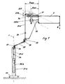
- FIG. 7 differs from FIGS. 3 to 6 in principle by an additional horizontal arm 29, which surrounds the support arm 2 by a vertical and pivotable about a horizontal axis.
- a support roller 30 is displaceable by means of a spindle along a balance arm 22b. It is irrelevant whether the roller 30 is seated on a nut, or whether it is mounted on a shoe which is longitudinally displaceable on a rod (extension of the upper arm of the support arm 2) by means of a parallel threaded spindle.
- a bracket 207 rests on the roller 30 and is guided on the one hand in a housing-fixed parallel guide 33 of the tare gear. On the other hand, it is connected to the cable of the cable 24d. If there is a longitudinal adjustment of the roller 30 through the spindle 31, this leads to a different counterbalancing weight attack on the cable 24d on the balance arm 22b. At the point 34, the cable 24 is torsionally coupled, so that the support arm 2 can pivot about a bearing 35 in a horizontal plane.
- balance weight AGb Inside the stator column 21 b is the balance weight AGb, which is preferably woodrekoppelt again via a rotary coupling 34.
- the balance weight AGb is preferably designed for transport reasons and for facilitated on-site assembly at least two parts.
- the relatively heavy balance weight AGb is distributed symmetrically about the vertical axis 1 of the column stand 21 b and advantageously causes a lowering of the overall center of gravity in the direction of the stand base 20.
- the balancing arm 22b corresponds approximately to the arm 3 from FIG.
- the spindle 31 performs approximately the same function as 19a of Fig.6.
- the bracket 207 has a similar function as the carriage 7 and its cheek 307 of Figure 6 and the roller 30 is approximately functionally identical to the roller 8 of Figure 6.
- the effective lengths h max -h min on the compensating arm 22b correspond to the lengths h max -h min on the arm 3 from FIG. Due to the guide 308a (Fig.6), or 308b (Fig.7), the cosine correction is ensured in both structures.
- rollers 36, 37 may be designed as a gear roller according to the construction according to FIG. 3 a in order to effect a transmission or reduction on the cable 24 d.
- Figure 9 shows a cable according to the invention constructed with a simple pulley.
- This includes a roller 55 which is movably positioned between the rollers 36 and 37.
- the cables 24a-c wrap around the roller 55 and are secured to the housing at 424. With this structure, this results in a translation of 2: 1. Within the scope of the invention are also other translations possible. The skilled person knows comparable hoists for hoists.
- roller 55 of the pulley 52 which has three parallel guide grooves 55a, 55b and 55c for receiving the three cables from the cable 24a, 24b and 24c therein.
- the roller 55 carries a roller yoke 85, which in turn is connected to the tethers 124a, 124b and 124c which provide the tensile force, e.g. to the bracket 207 (Fig.7) or to the shoe 23 (Fig.8) transmitted.
- FIG. 11 shows a stand structure constructed according to the invention with a microscope as a load G on a pivoting carrier 79, which is held by an integrated parallelogram carrier 2b.
- the carrier 2b is pivotally mounted on a bearing 119 of a horizontal arm 29, which is mounted on the stator column 21.
- a bow handle 88 serves as a transport aid and a device box 89 is used in addition to the inclusion of controls, power, lighting, etc. as additional Kippschreibsverêtung according to the structure MS. 1
Description
Die Erfindung betrifft ein Stativ, insbesondere für Operationsmikroskope. Operationsmikroskope müssen über einen vorgegebenen Bereich leicht schwenkbar sein und sollten die danach eingestellte Position beibehalten. Aus diesem Grund sind bei einer Gruppe von bekannten Stativen Ausgleichsgewichte vorgesehen, die das Gewicht des Mikroskops und seiner Zusatzeinrichtungen kompensieren. Am häufigsten werden die Ausgleichsgewichte balkenwaagenartig angeordnet. Besondere Ausbildungsformen solcher Balkenwaagenanordnungen sind beispielsweise der Aufbau "OHS™" der Anmelderin, bei dem über Parallelogrammträger Ausgleichsgewichte von oben nach unten verlegt sind, sodass der Gesamtschwerpunkt des Stativs im unteren Bereich des Stativaufbaus liegt. Der Prinzipaufbau des OHS™ ist in der internationalen Patentanmeldung WO 97/13997 (1997) und der korrespondierenden US 6 129 319 symbolisch dargestellt.The invention relates to a tripod, in particular for surgical microscopes. Surgical microscopes must be able to pivot slightly over a given range and should retain the posture set thereafter. For this reason, balancing weights are provided in a group of known tripods which compensate for the weight of the microscope and its ancillary equipment. Most often, the balance weights are arranged balancing scale. Special training forms such Balkenwaagenanordnungen example, the structure "OHS ™" by the applicant, in the parallelogram carrier balancing weights are laid from top to bottom, so that the overall center of gravity of the tripod is in the lower part of the tripod structure. The basic structure of the OHS ™ is shown symbolically in the international patent application WO 97/13997 (1997) and the corresponding US Pat. No. 6,129,319.
Der Gewichtsausgleich für die leichte Bedienbarkeit eines Mikroskops bzw. Beweglichkeit desselben im Raum und für die diesbezügliche Kompensation von Gewichtsänderungen am Mikroskop durch Hinzugeben oder Wegnehmen von Zusatzeinrichtungen am Mikroskop erfolgt bei einem bekannten Stativ "MS 1" der Anmelderin über eine Druckfeder, die einen Parallelogrammträger diagonal abstützt. Dieser Parallelogrammträger dient beim Aufbau MS 1 als schwenkbarer horizontaler Träger für das Mikroskop. Die besondere Parallelträgerkonstruktion wurde durch die Anmelderin in der europäischen Patentanmeldung EP 433426 A1 (WO 91/472) veröffentlicht. In der internationalen Patentanmeldung WO 99/1693 (1999) ist der Aufbau des MS 1 symbolisch dargestellt.The weight compensation for the ease of use of a microscope or mobility of the same in the room and for the corresponding compensation of weight changes to the microscope by adding or removing additional equipment on the microscope is done in a known tripod "MS 1" the applicant via a compression spring diagonal a parallelogram supported. This parallelogram support is used in the construction of
Für ein verbessertes Kippverhalten des Stativs sieht das MS 1 als Ausgleichsgewicht einen Schaltkasten vor, der sowohl die elektrische Stromversorgung für das Mikroskop, als auch seine Beleuchtungseinrichtung, seine Steuerungen o.dgl. und gegebenenfalls ein Zusatzgewicht enthält. Der Schaltkasten ist starr an der vertikalen Tragsäule des Stativs montiert und übernimmt dort lediglich einen Gewichtsausgleich um die vertikale Achse der senkrechten Tragsäule im Hinblick auf eine Verbesserung des Kippmomentes des Stativs.For an improved tilting behavior of the stand, the MS 1 provides as a balance weight before a switch box, the like, both the electrical power supply for the microscope, as well as its lighting device, its controls or the like. and optionally an additional weight. The control box is rigidly mounted on the vertical support column of the tripod and takes over there only a weight balance around the vertical axis of the vertical support column in terms of improving the tilting moment of the tripod.
In der DE 19742050 A1 (1999) wird Bezug genommen auf einen Aufsatz "Gewichtsausgleich an feinmechanischen Geräten" von H. Hilpert in Heft 2/1965 der Zeitschrift Feingerätetechnik, 14. Jahrgang.In DE 19742050 A1 (1999) reference is made to an article "Weight balance on precision mechanical equipment" by H. Hilpert in
In diesem Artikel aus dem Jahr 1965 wird auf verschiedene gewichtskompensatorische Massnahmen in der Feingerätetechnik eingegangen, die in erster Linie nicht durch Gegengewichte, sondern durch federkompensatorische Massnahmen (wie vergleichsweise auch bei der Parallelträgerkonstruktion des MS 1) erzielt werden.This article from 1965 deals with various weight compensatory measures in precision engineering, which are primarily achieved not by counterweights but by spring compensatory measures (as in the case of the parallel beam design of the MS 1).
Die DD 221571 A1 (1985) zeigt einen Stativaufbau mit einem Hebelarm, der durch eine Feder, die über einen Seilzug mit dem Hebelarm verbunden ist, Gewicht kompensiert. Am distalen Ende des Hebelarms befindet sich das Operationsmikroskop. Die Grundjustierung dieses Operationsmikroskops erfolgt über eine Gewindespindel, mit der das gehäusefeste Ende der Feder weiter vom Hebelarm weggezogen oder näher zu ihm hingeführt wird. Gewichtsänderungen am Mikroskop werden dadurch kompensiert, dass der Anlenkpunkt des Seilzugs relativ zum Hebelarm über eine Spindel verstellt wird.DD 221571 A1 (1985) shows a tripod structure with a lever arm, which compensates by a spring which is connected via a cable to the lever arm, weight. At the distal end of the lever arm is the surgical microscope. The basic adjustment of this surgical microscope via a threaded spindle, with the housing-fixed end of the spring is further pulled away from the lever arm or closer to him. Weight changes on the microscope are compensated by the fact that the articulation point of the cable is adjusted relative to the lever arm via a spindle.
Um in allen möglichen Winkellagen des Stativs ein gleichmässiges Gegenmoment zu erzielen, ist es erforderlich, dass sich der erwähnte Angriffspunkt des Seilzugs auf einer Verbindungslinie zwischen der Drehachse des Hebelarms und dem Masseschwerpunkt des Mikroskops befindet. Dies wird durch das Betätigen einer Verstelleinrichtung in Form einer Schnecke erreicht, die eine mit dem Hebelarm verbundene Scheibe um die Drehachse des Hebelarms dreht.In order to achieve a uniform counter-torque in all possible angular positions of the tripod, it is necessary that the mentioned point of application of the cable is located on a connecting line between the axis of rotation of the lever arm and the center of mass of the microscope. This is achieved by operating an adjusting device in the form of a worm which rotates a disc connected to the lever arm about the axis of rotation of the lever arm.
Bei diesem Aufbau sind somit eine Fülle von Verstellmassnahmen erforderlich, um den gewünschten Effekt zu erzielen. Abgesehen davon, zwingt die Konstruktion dieses bekannten Aufbaus zu einem hohen Gesamtschwerpunkt des Stativs, da sämtliche Gewichtsausgleichsvorrichtungen oberhalb des Mikroskops angeordnet sind.In this structure, thus a wealth of adjustment measures are required to achieve the desired effect. Apart from that, the construction of this known construction forces a high overall center of gravity of the stand, since all counterbalancing devices are arranged above the microscope.
Die DE 3739080 A1 (1989) gibt ebenso eine Federvorrichtung zum Gewichtsausgleich für Stative an, bei der Seilzüge in Kombination mit Federn zu einem Gewichtsausgleich führen sollen. Dabei geht es um die Kraftunterstützung einer Verstellbewegung, die eine Bedienperson an einem Handgriff ausübt. Es geht dort allerdings nicht darum, eine Last in einem "schwebenden Zustand" zu halten, wie dies bei Operationsmikroskopen gewünscht ist.DE 3739080 A1 (1989) also provides a spring device for weight balance for tripods, in which cables in combination with springs should lead to a weight balance. It is about the power assistance of an adjustment that exerts an operator on a handle. It However, it is not about keeping a load in a "floating state", as is the case with surgical microscopes.
Die US 5 253 832 beschreibt ein Stativ mit einem Ständer und einem daran schwenkbar angeordneten Tragarm für eine Last. Zum Gewichtsausgleich und zur Balancierung ist der Tragarm über einen Seilzug mit einer Feder verbunden. Über die Seilzug-Feder-Konstruktion wird jedoch keine Verbesserung der Kippsicherheit erreicht.US 5,253,832 describes a tripod with a stand and a support arm pivotally mounted thereto for a load. For balancing and balancing the arm is connected via a cable with a spring. About the cable-spring construction, however, no improvement in the tilting security is achieved.
Die FR 2 605 757 beschreibt einen fotografischen Reflektor mit einem Stativ. Das Stativ ist mit einer Seilzug-Feder-Konstruktion zum Gewichtsausgleich ausgestattet. Auch hier trägt die Seilzug-Federkombination nicht zur Verbessung der Kippsicherheit bei.
Demgegenüber ist in der US 5397323 (1992) ein Operationsroboter mit Parallelogrammträgern vorgestellt, bei dem unter anderem das Gewicht des Instruments über einen Seilzug mittels Gegengewicht gewichtskompensiert gehalten wird. Der Seilzug ist dabei geschlossen aufgebaut, d.h. über eine obere und untere Umlenkrolle wird je ein Seil vom Instrument bis zum Gegengewicht geführt (Fig.3 der US -323).In contrast, in US Pat. No. 5,397,323 (1992), an operation robot with parallelogram supports is presented in which, inter alia, the weight of the instrument is held weight-compensated by means of a counterweight via a cable pull. The cable is built closed, i. A rope is guided from the instrument to the counterweight via an upper and lower deflection pulley (FIG. 3 of US-323).
Ein solcher Aufbau setzt voraus, dass das Gegengewicht in unmittelbarer Nähe des Instruments angebracht ist. Er wäre daher für den Einsatz an einem Operationsmikroskop nur schlecht anwendbar.Such a construction presupposes that the counterweight is mounted in the immediate vicinity of the instrument. It would therefore be poorly applicable for use on a surgical microscope.
Die DE 19742050 A1 (1999) offenbart einen Stativaufbau mit einem schwenkbaren Parallelogrammträger, der über einen Seilzug und eine Gewichtsausgleichsfeder so gewichtskompensiert ist, dass die zusätzlich vorhandenen Ausgleichsgewichte, die nach dem oben erwähnten Waagenprinzip wirken, besonders klein ausgebildet sein können. Bei diesem Aufbau wird der Seilzug in besonderer Form geführt, um den durch den endlichen Umlenkradius bedingten Gewichtsausgleichsfehler in einem weiten Schwenkbereich des Schwenkarms zu minimieren. Der Gewichtsausgleichsfehler wird durch diese Massnahme jedoch nicht eliminiert, sodass bei bestimmten Schwenkpositionen nach wie vor ein Verstellen der Ausgleichsgewichte erforderlich ist, um die gewünschte Balancierung zu erreichen.DE 19742050 A1 (1999) discloses a stand construction with a pivotable parallelogram carrier, which is weight-compensated via a cable pull and a weight compensating spring so that the additionally present balance weights, which act according to the above-mentioned balance principle, can be made particularly small. In this construction, the cable is guided in a special form in order to minimize the weight compensation error caused by the finite deflection radius in a wide pivoting range of the pivoting arm. However, the counterbalancing error is not eliminated by this measure, so that at certain pivoting positions an adjustment of the counterweights is still required to achieve the desired balance.
Die US 6070839 (2000) offenbart einen weiteren Aufbau mit einem Schwenkarm und einer Seilzug-Feder-Konstruktion, die einen reinen Gewichtsausgleich - im Sinne des oben erwähnten diagonalen Parallelträgerarmausgleichs beim MS1 - ermöglicht, ohne jedoch auch Ausgleichsmomente zu einer Verbesserung der Kippsicherheit beizutragen. Im Falle von Gewichtsänderungen wird der Anlenkpunkt des Seilzugs, vergleichbar dem Aufbau in der erwähnten DD 221571, über eine Spindel verschoben.The US 6070839 (2000) discloses a further structure with a pivoting arm and a cable-spring construction, which allows a pure weight balance - in the sense of the above-mentioned diagonal parallel Trägerarmausgleichs in MS1 - but without also contribute compensation moments to improve the stability against tilting. In the case of weight changes the pivot point of the cable, similar to the structure in the mentioned DD 221571, moved over a spindle.
Die US 5253832 (1999) beschreibt ein Stativ mit einer zentral angeordneten Zugfeder für den Gewichtsausgleich. Dieser Aufbau bietet keine einfache Verstellmöglichkeit für geänderte Lasten. Die Zugfeder selbst hat ein geringes Eigengewicht, sodass sie zwar dem Gewichtsausgleich, jedoch nicht der Balance um die vertikale Mittelachse (Kippsicherheit) dient.US 5253832 (1999) describes a tripod with a centrally arranged tension spring for weight compensation. This structure offers no easy adjustment for changed loads. The tension spring itself has a low dead weight, so that it serves the weight balance, but not the balance around the vertical center axis (stability).
In der EP 700665 A1 (1995) ist des Weiteren ein Stativaufbau angegeben, der im Wesentlichen über Hebel und Hebelwinkelarme für einen Gewichtsausgleich sorgt. In der Fig.13 und 14 dieser veröffentlichten Patentanmeldung ist ein Bewegungsübertragungsmechanismus 157 vorgestellt, der Bewegungen des Mikroskopkörpers um Bewegungsachsen auf einen Schwenkarm überträgt. Durch diesen sehr komplizierten Aufbau mit vielen Teilen wird zwar ein gewisser Gewichtsausgleich geschaffen, andererseits ist jedoch eine Vielzahl von Hebeln und Winkelhebeln erforderlich, da der Gewichtsausgleich schlussendlich an solchen Hebeln montiert ist.In EP 700665 A1 (1995), furthermore, a stand structure is specified, which essentially ensures leverage and lever angle arms for weight compensation. In FIGS. 13 and 14 of this published patent application, a motion transmission mechanism 157 is presented which transmits movements of the microscope body about axes of movement to a pivoting arm. Although a certain weight compensation is created by this very complicated structure with many parts, but on the other hand, a variety of levers and angle levers is required because the weight compensation is finally mounted on such levers.
Bei dem MS 1 der Anmelderin, sowie bei verschiedenen Aufbauten anderer bekannter Stative und bei den oben angegebenen Stativen ist der Hauptträger, der unmittelbar die Last aufnimmt, oftmals nicht direkt an der vertikalen Ständersäule des Stativs befestigt, sondern an einem von dieser Säule abragenden zusätzlichen Horizontalarm. Die Kippsicherheit wird bei diesen Aufbauten in erster Linie durch eine entsprechende Ausbildung des Stativfusses erzielt, der entsprechend gross und schwer sein muss. Die Gewichtskompensation wird, wie schon weiter oben angegeben, durch eine Feder diagonal im Parallelogrammträger oder andere oben angegebene Massnahmen bewirkt.In Applicant's
Eine Verbesserung der Kippsicherheit und ein gewisser Ausgleich zur Kippverhinderung ist zwar - wie oben angegeben - gegebenenfalls durch die besondere Anordnung eines Schaltkastens o.dgl. möglich.An improvement in the anti-tipping and a certain compensation for tipping prevention is - as indicated above - optionally by the special arrangement of a control box or the like. possible.
Aus der US 4 515 333 ist ein Stativ für Operationsmikroskop bekannt, das eine Ständersäule und einen daran schwenkbaren Tragarm aufweist. Zur Balancierung des Tragarms ist an einem Ende ein Seilzug befestigt, der an seinem anderen Ende mit einer Feder verbunden ist. Durch Schwenken des Tragarms in einer Vertikalebene, wird die Feder über den Seilzug mehr oder weniger gespannt. Abgesehen davon, dass derartige Federn nur in einem relativ kleinen Bereich konstant arbeiten, trägt die Feder aufgrund ihres geringen Gewichts auch hier nicht zu einer Verbesserung der Kippsicherheit bei.From US 4 515 333 a tripod for surgical microscope is known, which has a stand column and a support arm pivotable thereon. To balance the support arm, a cable is attached at one end, which is connected at its other end with a spring. By pivoting the support arm in a vertical plane, the spring is stretched over the cable more or less. Apart from the fact that such springs work only in a relatively small area constant, the spring does not contribute to an improvement in the anti-tipper due to their low weight here.
Gegenüber den bekannten Aufbauten liegt der Erfindung die Aufgabe zugrunde, ein neuartiges Stativ für Operationsmikroskope zu schaffen, das kippsicherer ist, möglichst wenig Volumen aufweist und über eine optimale Gewichtskompensation verfügt. Unter Gewichtskompensation ist einerseits die Kompensation des Gewichts der Last zu verstehen, andererseits aber auch die Kompensation allfälliger Änderungen dieses Gewichts.Compared to the known structures, the invention has for its object to provide a novel tripod for surgical microscopes, which is resistant to tipping, having as little volume and has an optimal weight compensation. Weight compensation is, on the one hand, the compensation of the weight of the load to understand, on the other hand, but also the compensation of any changes in this weight.
Gelöst wird diese Aufgabe erstmals durch ein System, bei dem über einen Seilzug und wenigstens eine Umlenkrolle eine konstante Ausgleichskraft, z.B. ein Gewicht für den Gewichtsausgleich eingesetzt ist, wobei das Gewicht entweder in der Nähe der Ständersäule, z.B. auf der der Last gegenüberliegenden Seite, konzentrisch zur Ständersäule oder bevorzugt innerhalb der Ständersäule untergebracht ist.This problem is solved for the first time by a system in which, via a cable pull and at least one deflection roller, a constant balancing force, e.g. a weight is used for weight balance, the weight either in the vicinity of the column, e.g. on the opposite side of the load, concentric with the column stand or preferably housed within the column stand.
Damit liegt der Gesamtschwerpunkt des Stativs sehr tief und ist in Richtung Ständersäule bzw. Stativfuss legbar, sodass das Kippverhalten schon aus diesem Grund verbessert wird.Thus, the overall center of gravity of the tripod is very deep and can be placed in the direction of the column stand or tripod foot, so that the tilting behavior is improved for this reason.
Durch den erfindungsgemässen Seilzug und die wenigstens eine Umlenkrolle ist es zudem möglich, das Ausgleichsgewicht an nahezu beliebigen Stellen anzubringen, bzw. den Seilzug über verschiedenst ausgebildete Tragarme (Horizontalarm) oder Tragarmteile zu führen, ohne nennenswerten Platzbedarf und ohne nennenswerte zusätzliche Gewichte über den Seilzug.Due to the inventive cable and the at least one pulley, it is also possible to attach the balance weight at almost any point, or to lead the cable via various trained support arms (horizontal arm) or Tragarmteile without significant space requirements and without significant additional weights on the cable.
Es ist zwar schon ein Bodenstativ bekannt geworden (Standard und Universal), das über eine Umlenkrolle ein Kunststoffband einsetzt, um ein Ausgleichsgewicht in einer Ständersäule mit einem Ring um die Ständersäule zu verbinden, der einen waagrecht abragenden Arm stützt, an dem die Last montierbar ist. Dieser Aufbau erlaubt keinen Lastausgleich bei einem schwenkbaren Träger und insbesondere erlaubt er keinen Ausgleich bei einem Träger, der in sich in einer Horizontalebene schwenkbar ist (um die Ständersäule und um eine weitere Achse schwenkbar). Da das Ausgleichsgewicht bzw. die Bänder nicht am Schwenkarm direkt angreifen, wird die Ständersäule bzw. die Anlenkung des Tragarms an der Ständersäule stark auf Verkantung (Drehmoment des Armes an der Ständersäule) belastet. Ausserdem erfordert der bekannte Aufbau bei einer Gewichtsänderung an der Last eine Änderung des Ausgleichsgewichtes durch Hinzugeben oder Hinwegnehmen von Gewichten. Tut man das nicht, muss man den Ring an der Ständersäule fixieren, um ein Driften zu verhindern. Ein automatischer Balancierausgleich ist bei diesem bekannten Aufbau somit insgesamt nicht möglich.Although it is already known a floor stand (standard and universal), which uses a plastic belt over a pulley to connect a balance weight in a column stand with a ring around the column stand, which supports a horizontally projecting arm on which the load is mountable , This structure does not allow load balancing in one pivotable carrier and in particular it does not allow compensation in a carrier which is pivotally in a horizontal plane (about the column stand and pivotable about another axis). Since the balance weight or the bands do not attack directly on the swivel arm, the column or the articulation of the support arm on the stand column is heavily loaded on tilting (torque of the arm on the column stand). In addition, the known structure requires a change in weight on the load, a change in the balance weight by adding or taking away weights. If you do not do that, you have to fix the ring on the column to prevent drifting. An automatic Balancierausgleich is thus not possible in this known structure.
Bei Weiterbildungen der Erfindung zeigt es sich als zweckmässig, wenn der Seilzug drehentkoppelt ist, d.h. wenn bei einem Schwenken des Tragarmes in einer horizontalen Ebene das Seil nicht auf Torsion belastet wird, bzw. sich allfällige Torsionsbelastungen an den Drehentkoppelstellen lösen. Alternativ oder zusätzlich können auch Seile verwendet werden, deren Aufbau gegenüber Torsionsbelastungen tolerant ist. Solche Seile sind insbesondere beispielsweise links-rechts-geflochtene Seile, oder Kombinationen aus links- und rechtsgeflochtenen Seilen.In further developments of the invention, it turns out to be expedient if the cable is dreenktkoppelt, ie when a swinging of the support arm in a horizontal plane, the rope is not loaded on torsion, or solve any torsional stresses on the pivotal coupling points. alternative or in addition ropes may be used, the construction of which is tolerant of torsional loads. Such ropes are in particular, for example, left-right braided ropes, or combinations of left and right braided ropes.
Eine besondere Weiterbildung der Erfindung sieht vor, das Ausgleichsgewicht über eine Flaschenzugseilrolle aufzuhängen, sodass es zu einer Kraftübersetzung kommt und das Gewicht des Ausgleichsgewichts besonders hoch gewählt werden kann, was zu einer verbesserten Standfestigkeit des Stativs aufgrund des besonders tiefliegenden Schwerpunktes führt.A particular embodiment of the invention provides to hang the balance weight on a Pulley, so it comes to a power transmission and the weight of the balance weight can be particularly high, resulting in improved stability of the tripod due to the particularly low center of gravity.
Umgekehrt liegt im Rahmen der Erfindung eine besondere Ausbildung, bei der mit Hilfe eines umgekehrten Flaschenzugsystems das Ausgleichsgewicht nur halb so gross dimensioniert werden kann, indem die Übersetzung beim Ausgleichsgewicht zu einem vergrösserten Weg, aber zu einer vergrösserten resultierenden Kraft für den Gewichtsausgleich führt.Conversely, within the scope of the invention is a special education, in which with the help of a reverse pulley system, the balance weight can be dimensioned only half as large by the translation of the balance weight leads to an enlarged way, but to an increased resulting force for weight balance.
Abgesehen von einem Flaschenzug sind erfindungsgemäss beliebige Übersetzungsvarianten über ein Rollengetriebe möglich, bei dem der Seilzug unterbrochen ist und an der Unterbrechungsstelle einerseits an einer Rolle mit grösserem Durchmesser angreift und andererseits das andere Ende des anderen Stückes des Seilzugs an einer mit dieser Rolle starr verbundenen kleineren Rolle angreift, sodass es zu einer Über- oder Untersetzung der Kraft des Ausgleichsgewichtes kommt. Anstelle von Rollen können auch vergleichbare Hebelgetriebe zum Einsatz kommen.Apart from a pulley according to the invention any translation options on a roller transmission are possible in which the cable is broken and attacks at the point of interruption on the one hand to a larger diameter roll and on the other hand, the other end of the other part of the cable to a roll rigidly connected to this smaller role engages, so that there is an over- or reduction of the force of the balance weight. Instead of rollers, comparable lever mechanisms can also be used.
Eine andere Ausgestaltung der Erfindung sieht eine Art Waagebalken als Tragarm für die Last vor, der an seinem lastabgewandten Ende eine Führung aufweist, entlang der die Angriffsstelle eines Seilzugs (Gleitschuh) verschiebbar ist. Der Seilzug ist an seinem anderen Ende mit einem Ausgleichsgewicht verbunden, das im Bereich der Ständersäule in der Höhe frei schwebend angebracht ist.Another embodiment of the invention provides a kind of balance beam as a support arm for the load, which has at its load-remote end a guide along which the point of attack of a cable (sliding block) is displaceable. The cable is connected at its other end with a balance weight, which is freely suspended in height in the area of the column stand.
Eine bevorzugte und einfache Konstruktion sieht eine an einem Ausgleichsarm verschiebbar gelagerte Rolle vor, die einen nicht verschiebbaren Bügel beaufschlagt, an dem der Seilzug angreift. Durch diese Konstruktion wird erreicht, dass bei einem Schwenken des Tragarms automatisch die proportionale Änderung der Angriffsstelle der Rolle am Bügel angepasst wird, sodass die gegeneinander wirkenden Momente in jeder Winkelposition die gleiche Proportion zueinander haben.A preferred and simple construction provides a displaceably mounted on a balance arm roller, which acts on a non-displaceable bracket on which the cable attack. By this construction it is achieved that upon pivoting of the support arm, the proportional change of the point of engagement of the roller is adapted to the bracket automatically, so that the opposing moments in each angular position have the same proportion to each other.
Bei Anwendung eines zusätzlichen Horizontalarmes, wie z.B. beim MS 1 wird so ein universell einsetzbares, über zwei Vertikalachsen schwenkbares Stativ mit ausgezeichnetem Gewichtsausgleich und verbesserter Kippsicherheit geschaffen.When using an additional horizontal arm, e.g. With the
In einer weiter Ausgestaltung der Erfindung ist das Ausgleichsgewicht entlang der Ständersäule gleit- oder rollgelagert oder reibungslos geführt. Auch kann wenigstens eine der Spindelverstellungen elektromotorisch, elektromagnetisch, hydraulisch und/oder pneumatisch antreibbar ausgebildet sein.In a further embodiment of the invention, the balance weight along the column stand is sliding or rolling stored or smoothly. Also, at least one of the spindle adjustments can be designed to be electromotively, electromagnetically, hydraulically and / or pneumatically drivable.
In einer vorteilhaften Weiterbildung der Erfindung ist der Antrieb mit einer Bremse für das Blockieren der Arme ausgestattet und/oder wenigstens eine der Spindelverstellungen computergesteuert ausgebildet.In an advantageous development of the invention, the drive is equipped with a brake for blocking the arms and / or at least one of the spindle adjustments is computer-controlled.
Vorteilhaft kann an der vertikalen Ständersäule ein Geräteschrank mit zusätzlicher Gewichtsausgleichsfunktion angeordnet sein.Advantageously, a device cabinet with additional weight compensation function can be arranged on the vertical column stand.
In einer weiteren Ausgestaltung ist ein Horizontalarm vorgesehen, der an der Ständersäule in einer Horizontalebene selbst schwenkbar ist und der den Tragarm in einer Horizontalebene schwenkbar lagert.In a further embodiment, a horizontal arm is provided which is pivotable on the column stand in a horizontal plane and which supports the support arm pivotally in a horizontal plane.
Außerdem ist es vorgesehen, dass wenigstens eine Umlenkrolle mittels einer Spindel in ihrer Relativposition zum gegebenenfalls verschiebbaren Anlenkpunkt des Seilzugs verstellbar ausgebildet ist.In addition, it is provided that at least one deflection roller by means of a Spindle is designed to be adjustable in its relative position to the optionally displaceable articulation point of the cable.
Ferner kann es vorgesehen sein, dass das Ausgleichsgewicht aus wenigstens zwei Teilgewichten aufgebaut ist.Furthermore, it can be provided that the balance weight is made up of at least two partial weights.
In einer weiteren Ausgestaltung der Erfindung sind in einem Seilzug wenigstens zwei parallele Seile vorgesehen, bei denen vorzugsweise die Wickelrichtung gegenläufig ausgebildet ist.In a further embodiment of the invention, at least two parallel cables are provided in a cable, in which preferably the winding direction is formed in opposite directions.
Anhand von beispielhaften Skizzen werden die Erfindung, Varianten und Weiterbildungen dazu näher erläutert. Es zeigen dabei
- Fig.1 -
- symbolisch einen theoretischen Aufbau mit mind. zwei vertikalen Achsen und einem Ausgleichsgewicht nach einem Waagenprinzip, das aus Gründen der zu geringen Kippsicherheit von der vorliegenden Erfindung verworfen wurde;
- Fig.2 -
- eine Variante des Aufbaus gemäss Fig.1, bei dem der Parallelogrammträger unmittelbar an der vertikalen Ständersäule befestigt ist; diese Variante ist durch die Erfindung ebenso verworfen, da sie den freien Arbeitsraum zu stark einschränkt;
- Fig.2a - eine
- Draufsicht auf einen Aufbau nach Fig.1
oder 2 in Arbeitsstellung; - Fig.3 und 3a -
- einen erfindungsgemässen Aufbau nach dem Waagenprinzip;
- Fig.4 und 5 -
- Varianten eines erfindungsgemässen Aufbaus mit Tariergetriebe, jedoch ohne Cosinus-Ausgleich;
- Fig.6 -
- eine Variante eines erfindungsgemässen Aufbaus mit Cosinusausgleich;
- Fig.7 -
- einen Aufbau mit modifiziertem Tariergetriebe und Seilzug über einen Horizontalarm mit Cosinusausgleich;
- Fig.8 -
- eine Variante des Aufbaus nach Fig.7 ohne Cosinusausgleich;
- Fig.9 -
- eine Symboldarstellung des Flaschenzugs innerhalb des Seilzugs;
- Fig.10 - den
- oberen Teil des Flaschenzugs in Schrägansicht und
- Fig.11 -
- einen Stativaufbau mit einem Operationsmikroskop als Last.
- Fig.1 -
- symbolically a theoretical design with at least two vertical axes and a balance weight according to a balance principle, which has been rejected by the present invention for reasons of low tilting safety;
- Fig.2 -
- a variant of the structure according to Figure 1, in which the parallelogram is attached directly to the vertical column stand; this variant is also rejected by the invention, since it restricts the free working space too much;
- Fig.2a - a
- Top view of a structure according to Figure 1 or 2 in working position;
- 3 and 3a -
- an inventive construction according to the balance principle;
- 4 and 5 -
- Variants of a construction according to the invention with a taring gear, but without cosine compensation;
- Fig.6 -
- a variant of an inventive construction with cosine compensation;
- Fig.7 -
- a structure with modified BCM and cable via a horizontal arm with cosine compensation;
- Fig.8 -
- a variant of the structure of Figure 7 without cosine compensation;
- Fig.9 -
- a symbol representation of the pulley within the cable;
- Fig.10 - the
- upper part of the pulley in an oblique view and
- Fig.11 -
- a tripod construction with a surgical microscope as a load.
Die Figuren werden übergreifend beschrieben, gleiche Bezugszeichen bedeuten gleiche Bauteile. Bezugszeichen mit gleichen Nummern, jedoch unterschiedlichen Indizes bedeuten geringfügig unterschiedliche Bauteile mit gleichen Aufgaben bzw. ähnlichen Wirkungen.The figures are described overarching, like reference numerals mean the same components. Reference numerals with the same numbers, but different indices mean slightly different components with the same tasks or similar effects.
Fig.1 zeigt ein Beispiel einer denkbaren Gewichtsausgleichsmassnahme nach dem Waagenprinzip, die um die vertikale Achse 1 der Anbringungsstelle des Tragarms 2a erfolgen würde. Eine solche Massnahme könnte zunächst die Kippsicherheit des Stativs jedoch noch nicht verbessern, da die allfällig angebrachten Zusatzgewichte AG wegen des Horizontaltragarms 29 zunächst noch auf derselben Seite der vertikalen Ständersäule 21 sind, auf der auch die Last G angreift. (Kippmoment gemäss Pfeil über dem wirksamen Abstand k) Nur dann, wenn man den Ausgleichsarm 22 entsprechend lang machen und ihn am Anlenkpunkt einbremsen würde, wobei er auch über die Achse der Ständersäule 21 ragen würde, könnte mit einem solchen Gewichtsausgleich gleichzeitig auch die Kippsicherheit verbessert werden. Dabei würde jedoch nachteiligerweise das Volumen des Gesamtaufbaus deutlich vergrössert werden. Beim Lösen der Bremse käme es ggf. zu einem Kippen. Abgesehen davon sind bei den herkömmlichen Stativen die Hauptträgerarme um ihre Montagepunkte nicht nur in der Höhe, sondern auch seitlich schwenkbar, wodurch Positionen (den Tragarm 2a um ca. 90° aus der Bildebene geschwenkt) entstehen können, bei denen auch bei verlängerten Waagenausgleichssystemen die gesamte Last auf einer Seite der Ständersäule 21 zu liegen kommt und daher die Kippgefahr wieder gross werden würde. Dieses müsste - wie in der Praxis versucht - durch einen ausreichend grossen oder schweren Stativfuss 20 ausgeglichen werden.1 shows an example of a conceivable weight compensation measure according to the balance principle, which would take place about the
In Fig.2 sieht man eine Variante zum Aufbau nach Fig.1, bei der der Angriffsort des Parallelogrammträgers 2b an die vertikale Säule 21 des Stativs verlegt wurde. Hierdurch ist zwar das Kippverhalten verbessert, da das Ausgleichsgewicht AG auf der linken Seite der vertikalen Achse 1 liegt. Wie die Skizze jedoch andeutet, ist bei diesem Aufbau innerhalb des Kreises eine nur ungenügende Raumfreistellung für den Anwender die Folge. Der Parallelogrammträger 2b dringt in den Raum ein, der beim Aufbau gemäss Fig.1 freibliebe. Dies führt zu Behinderungen des Anwenders, z.B. bei der Arbeit an einem Operationstisch OT, wie symbolisch angedeutet.FIG. 2 shows a variant of the structure according to FIG. 1, in which the point of attack of the
In der Fig.2a sieht man die Draufsicht auf die Arbeitsstellung des Mikroskops gemäss Fig.1 oder 2.FIG. 2a shows the plan view of the working position of the microscope according to FIG. 1 or 2.
Demgegenüber ist der grundsätzliche Aufbau eines erfindungsgemässen Stativs gemäss Fig.3 insofern unterschiedlich, als das Ausgleichsgewicht in Form einer vertikal frei beweglichen Ausgleichslast AGa ausgebildet ist, deren Angriffspunkt am waagenförmigen Ausgleichsarm 22a, der eine Verlängerung des Tragarms 2c darstellt, montiert ist. Ein Gleitschuh 23, an dem ein Seilzug 24 befestigt ist, ist mittels einer Spindel 25 entlang des Ausgleichsarmes verschiebbar. Wird der Gleitschuh 23 weiter nach links geschoben, erhöht sich der Effekt (Moment) des Ausgleichgewichtes AGa und die Last G kann grösser bemessen werden. Der Seilzug 24 könnte theoretisch eine direkte Verbindung zwischen dem Gleitschuh 23 und dem Ausgleichsgewicht AGa bilden. Bei einer solchen direkten Verbindung entsteht jedoch beim Verschwenken des Tragarms 2c ein Cosinusfehler im wirksamen Ausgleichsgewicht durch die Schrägstellung des Seilzugs 24.In contrast, the basic structure of a tripod according to the invention according to Figure 3 is different in that the balance weight is designed in the form of a vertically freely movable compensation load AGa, the point of application on the balance-shaped compensating
In der dargestellten, verbesserten Ausbildungsform wirkt der Seilzug jedoch auf eine Umlenkrolle 26, deren Drehpunkt starr zur Stativsäule 21 festgelegt ist. Dies bewirkt, dass das Seil des Seilzugs 24 im Bereich des Ausgleichsgewichts AGa und darüber seine Parallelposition zur Ständersäule 21 nicht verlässt. In seinem Bereich oberhalb der Umlenkrolle 26 folgt das Seil des Seilzugs 24 jedoch dem Gleitschuh 23, sodass dort eine Schrägstellung des Seiles in Bezug auf die Ständersäule 21 möglich ist.In the illustrated, improved embodiment of the cable, however, acts on a
Fig.3a zeigt eine Variante dieser Umlenkrolle 26, die gleichzeitig als Übersetzung dient: Der Seilzug 24 ist bei dieser Variante zweigeteilt, wobei der obere Teil 24a einerseits mit einer Rolle 26a verbunden ist und andererseits am Gleitschuh 23 befestigt ist. Der Gleitschuh 23 gleitet am Ausgleichsarm 22, der durch die Ständersäule 21 gehalten ist. Eine kleinere Umlenkrolle 26b ist mit der grösseren 26a starr verbunden. An ihr ist der untere Seilzug 24b befestigt, bzw. aufgewickelt, der andererseits mit dem Ausgleichsgewicht AGa verbunden ist. Ein Verschieben des Gleitschuhs 23 entlang des Ausgleichsarms 22 führt somit zu einer Rotation der Umlenkrolle 26a und zu einer drehgleichen Rotation der Umlenkrolle 26b um die Drehachse 27.3a shows a variant of this
Zumal der Radialabstand des Seilzugs 24b von der Drehachse 27 der Umlenkrolle 26b geringer ist als der Radialabstand des Seilzugs 24a zur Drehachse 27 der Umlenkrolle 26a, führt dies zu einer Untersetzung, d.h. das Ausgleichsgewicht AGa kann wesentlich grösser sein, als es sein müsste, wenn der Seilzug 24a direkt mit dem Seilzug 24b verbunden wäre. Für Fälle, bei denen das Ausgleichsgewicht kleiner sein soll, werden die beiden Rollen 26a und 26b vertauscht, woraus sich eine Übersetzung ergibt, bei der ein geringenres Ausgleichsgewicht eine grössere Ausgleichswirkung erzielt als im vorher beschriebenen Fall.Especially since the radial distance of the cable 24b from the axis of
In den Fig.3 und 3a ist das Ausgleichsgewicht AGa symbolisch ringförmig um die Ständersäule 21 angeordnet. Im Rahmen der Erfindung sind jedoch insbesondere Lösungen vorgesehen, bei denen das Ausgleichsgewicht innerhalb der Ständersäule 21 oder auch nur auf der Seite der Ständersäule 21 angeordnet ist, die der Last G um die Achse 1 gegenüberliegt.In FIGS. 3 and 3 a, the balancing weight AGa is arranged in a symbolic ring around the
In Fig.4 sieht man einen Aufbau ohne Ausgleichsarm 22. Bei diesem Aufbau übernimmt ein Arm 3, der mit dem Tragarm 2 starr verbunden ist, die Ausgleichsfunktion. Parallel zu ihm ist ein Arm 4a vorgesehen, der eine Spindel 19a aufweist. Gelenkig mit den beiden Armen 3 und 4a ist ein Verbindungsarm 5a vorgesehen, der in seiner Höhenlage mittels der Spindel 19a verstellt werden kann. Mit dem Verbindungsarm 5a ist ein Seilzug 24c verbunden, der um eine Umlenkrolle 26c geführt ist und an seinem anderen Ende das Ausgleichsgewicht AGb trägt. Die Rolle 26c kann bei Bedarf entsprechend der Darstellung in Fig. 3a ebenfalls zweiteilig ausgeführt sein und eine Unter- oder Übersetzungsfunktion aufweisen.In Figure 4 shows a structure without compensating
Als Variante zum Aufbau der Fig.4 ist der Aufbau von Fig.5 zu verstehen, bei dem einerseits das als Tariergetriebe wirkende Parallelogramm 6a vorgesehen ist, andererseits aber anstelle einer einfachen Abstützung 28 gemäss Fig.4 für die Umlenkrolle 26c eine spindelgesteuerte Abstützung 28b vorgesehen ist, die es ermöglicht, parallel zur Verschiebung des Verbindungsarms 5a auch die Position der Umlenkrolle 26c zu verändern. Dies bedeutet zwar mehr mechanischen und bauteilmässigen Aufwand, verbessert allerdings das Ausgleichsverhalten der Gesamtanordnung.As a variant to the structure of Figure 4, the construction of Figure 5 is to be understood, in which on the one hand acting as a
Die Lastausgleichseinheit 18 ist in der Fig. 6 aus dem Seilzug 24c, der Umlenkrolle 26c und dem Ausgleichsgewicht AGb aufgebaut. Bei einer Verstellung der Spindel 19a kommt es zu einer Höhenverlagerung des Verbindungsarms 5a an der Wange eines Wagens 7, der relativ zum Grundkörper 12 seitlich verschiebbar ist. Über den Seilzug 24c, der mit dem Wagen 7 verbunden ist, wird die konstante Ausgleichskraft FA auf den Wagen und damit auf den Verbindungsarm 5a aufgebracht, der lediglich durch seinen Abstand zum Grundkörper 12 die entsprechende Übersetzung für Gewichtsänderungen bei der Last G mit sich bringt.The load balancing unit 18 is constructed in FIG. 6 from the
Mit G ist die Last, bzw. das Operationsmikroskop angegeben, das am distalen Ende eines schwenkbaren Parallelogrammträgers 2 gehalten ist. Der obere Arm des Parallelogrammträgers 2 ist mit einem Arm 3 starr verbunden, der mit einem weiteren parallelen Arm 4 und einem Verbindungsarm 5 zu einem weiteren Parallelogramm 6a verbunden ist.G is the load, or the surgical microscope, which is held at the distal end of a
Dieses Parallelogramm 6a bildet das Tariergetriebe, in dem derThis
Verbindungsarm 5a in seiner parallelen Lage höhenverstellbar ist, wodurch die Geometrie des Parallelogramms 6a mittels Spindel 19a veränderbar ist. Ein Verschwenken des Parallelogrammträgers 2 nach oben oder nach unten führt zu einem Verschwenken des Parallelogramms 6a nach links oder nach rechts.
Die gestrichelte Linie hmax gibt die äusserste Lage des Verbindungsarms 5a an, bei der die grösste Hebelarmübersetzung besteht, d.h. bei der G die grösste Last annehmen kann. Beim Verschwenkvorgang des Parallelogrammträgers 2 verändert sich die Geometrie des Parallelogramms 6a woraus sich ein automatischer Kompensationseffekt (Cosinusausgleich) bei den Ausgleichskräften ergibt.The dashed line h max indicates the outermost position of the connecting
Dies nach der Formel M(G)=M(F) bzw. l1x G = h1 x F bzw. l2 x G = h2 x F, wobei M(G) das Moment der Last und M(F) das Moment der Gegenkraft angibt. 
Im Falle einer Gewichtsänderung an G muss man somit erfindungsgemäss lediglich den Verbindungsarm 5a parallel entlang dem Arm 3 verschieben, um dementsprechend hmin/max zu ändern, damit bei konstanter Ausgleichskraft FA die Kompensation der Gewichtsänderung erzielt wird.In the case of a change in weight at G, it is therefore necessary according to the invention to displace only the connecting
In den Fig.4 bis 6 ist das Gewicht AGb freihängend dargestellt. In der Praxis wird dieses natürlich in einem Käfig, an einer Führungsstange oder in der Ständersäule des Stativs untergebracht sein, wie dies beispielsweise in den Fig.7 und 8 angedeutet ist.In Figures 4 to 6, the weight AGb is shown freely suspended. In practice, this will of course be housed in a cage, on a guide rod or in the upright column of the tripod, as indicated for example in Figures 7 and 8.
Der Aufbau gemäss Fig.7 unterscheidet sich von den Fig.3 bis 6 grundsätzlich durch einen zusätzlichen Horizontalarm 29, der den Tragarm 2 um eine vertikale und um eine horizontale Achse schwenkbar trägt. Zwischen dem Horizontalarm 29 und dem Tragarm 2 ist eine andere Form des Tariergetriebes vorgesehen, als bisher beschrieben: Eine Stützrolle 30 ist mittels einer Spindel entlang eines Ausgleichsarms 22b verschiebbar. Es ist dabei unwesentlich, ob die Rolle 30 auf einer Mutter sitzt, oder ob sie auf einem Gleitschuh gelagert ist, der auf einer Stange (Verlängerung des oberen Arms des Tragarms 2) mittels paralleler Gewindespindel längsverschiebbar ist.The construction according to FIG. 7 differs from FIGS. 3 to 6 in principle by an additional
Ein Bügel 207 ruht auf der Rolle 30 und ist einerseits in einer gehäusefesten Parallelführung 33 des Tariergetriebes geführt. Andererseits ist er mit dem Seil des Seilzugs 24d verbunden. Kommt es zu einer Längsverstellung der Rolle 30 durch die Spindel 31, so führt dies zu einem unterschiedlichen Ausgleichsgewichtsangriff über den Seilzug 24d am Ausgleichsarm 22b. An der Stelle 34 ist der Seilzug 24 drehentkoppelt, damit der Tragarm 2 in einer Horizontalebene um ein Lager 35 schwenken kann.A
Entlang des Horizontalarmes 29 sind zwei weitere Umlenkrollen 36 und 37 vorgesehen, die den Seilzug 24d in das Innere der Ständersäule 21b führen. Im Inneren der Ständersäule 21 b befindet sich das Ausgleichsgewicht AGb, das vorzugsweise nochmals über eine Drehkopplung 34 drehentkoppelt ist. Das Ausgleichsgewicht AGb ist vorzugsweise aus Transportgründen und zur erleichterten Vorortmontage wenigstens zweiteilig ausgebildet.Along the
Wie ersichtlich, benötigt dieser Aufbau nur minimal Platz. Andererseits ist das relativ schwere Ausgleichsgewicht AGb symmetrisch um die vertikale Achse 1 der Ständersäule 21 b verteilt und bewirkt vorteilhafterweise eine Absenkung des Gesamtschwerpunktes in Richtung Stativfuss 20.As can be seen, this structure requires only minimal space. On the other hand, the relatively heavy balance weight AGb is distributed symmetrically about the
Verschiedene Bezugszeichen in Fig.7 haben folgende Entsprechungen. Der Ausgleichsarm 22b entspricht etwa dem Arm 3 aus Fig.6.Various reference numerals in Fig. 7 have the following equivalents. The balancing arm 22b corresponds approximately to the
Die Spindel 31 übt etwa die gleiche Funktion aus wie 19a aus Fig.6. Der Bügel 207 hat eine vergleichbare Funktion wie der Wagen 7 bzw. seine Wange 307 aus Fig.6 und die Rolle 30 ist etwa funktionsgleich mit der Rolle 8 aus Fig.6. Die wirksamen Längen hmax-hmin am Ausgleichsarm 22b entsprechen den Längen hmax-hmin am Arm 3 aus Fig.6. Bedingt durch die Führung 308a (Fig.6), bzw. 308b (Fig.7), ist die Cosinuskorrektur bei beiden Aufbauten sichergestellt.The
Der Aufbau von Fig.8 ist ein vereinfachter Aufbau gemäss Fig.7 und verzichtet auf die Rolle 30, sowie auf den Bügel 207. Stattdessen wird lediglich der Befestigungspunkt des Seilzugs 24d an einem Gleitschuh 23 festgelegt, der über die Spindel 31 entlang des Ausgleichsarms 22b verschiebbar ist. Bei Bedarf kann eine der Rollen 36, 37 als Getrieberolle entsprechend dem Aufbau gemäss Fig.3a ausgebildet sein, um eine Über- oder Untersetzung am Seilzug 24d zu bewirken.7, and dispenses with the
Da zwischen den hmin- und hmax-Einstellungen eine unterschiedliche Auswirkung der Seilzugsangriffsrichtung am Gleitschuh 23 auftritt, kommt es zu keinem ausreichenden Cosinusausgleich. Dies führt u.U. dazu, dass je nach Schwenkstellung des Tragarms 2 eine variable Kompensationswirkung durch das Ausgleichsgewicht AGb auftritt, so dass der Anwender eine Unbalance bemerken kann, weshalb dieser Aufbau nicht bevorzugt ist. Andererseits ist ein solcher erfindungsgemässer Aufbau jedoch gegenüber einem Aufbau mit diagonaler Federabstützung bei gleicher Kippsicherheit mit einer grösseren Ausladung produzierbar.Since between the h min and h max settings a different effect of Seilzugsangriffsrichtung on the
Zudem ist ein solcher Aufbau besonders preisgünstig herzustellen.In addition, such a structure is particularly inexpensive to manufacture.
In Fig.9 sieht man einen erfindungsgemäss aufgebauten Seilzug mit einem einfachen Flaschenzug. Dieser umfasst eine Rolle 55, die zwischen den Rollen 36 und 37 beweglich positioniert ist. Die Seilzüge 24a-c umschlingen die Rolle 55 und sind bei 424 am Gehäuse befestigt. Bei diesem Aufbau ergibt sich somit eine Übersetzung von 2:1. Im Rahmen der Erfindung sind auch andere Übersetzungen möglich. Der Fachmann kennt vergleichbare Flaschenzüge für Hebezeuge.In Figure 9 shows a cable according to the invention constructed with a simple pulley. This includes a
In Fig.10 sieht man Details der Rolle 55 des Flaschenzugs 52, die drei parallele Führungsrillen 55a, 55b und 55c aufweist, um die drei Seile aus dem Seilzug 24a, 24b und 24c darin aufzunehmen. Die Rolle 55 trägt einen Rollenbügel 85 und dieser wiederum ist mit den Halteseilzügen 124a, 124b und 124c verbunden, welche die Zugkraft z.B. zum Bügel 207 (Fig.7) oder zum Gleitschuh 23 (Fig.8) übertragen.In Fig. 10, details of the
In Fig.11 sieht man einen erfindungsgemäss ausgeführten Stativaufbau mit einem Mikroskop als Last G an einem Schwenkträger 79, der von einem integriert aufgebauten Parallelogrammträger 2b gehalten ist. Der Träger 2b ist an einer Lagerstelle 119 eines Horizontalarms 29 schwenkbar gelagert, der an der Ständersäule 21 gelagert ist. Ein Bügelgriff 88 dient als Transporthilfe und ein Gerätekasten 89 dient neben der Aufnahme von Steuerungen, Stromversorgung, Beleuchtung usw. auch als zusätzliche Kippsicherheitsverbesserung entsprechend dem Aufbau MS 1.FIG. 11 shows a stand structure constructed according to the invention with a microscope as a load G on a pivoting
Unter Trägern im Sinne der Patentansprüche sind sowohl einzelne Tragarme als auch Parallelogrammträger oder ähnliche Konstruktionen zu verstehen.Under carriers in the sense of the claims are both individual support arms and parallelogram or similar structures to understand.
- 1 - Vertikale Achse des vertikalen Ständers1 - vertical axis of the vertical stand
- 2 - Tragarm bzw. Parallelogrammträger2 - Support arm or parallelogram support
- 3 - Arm3 - arm
- 4a - Arm4a - arm
- 5a - Verbindungsarm5a - Connecting arm
- 6 a- Parallelogrammträger bzw. Tariergetriebe6 a- Parallelogram or taring gear
- 7 - Transferelement, vorzugsweise Wagen bzw. Schlitten7 - transfer element, preferably carriage or carriage
- 8 - Rolle8 - roll
- 12 - Tragbauteil bzw. Grundkörper12 - supporting component or basic body
- 18a - Federeinheit bzw. Lastausgleichseinheit18a - spring unit or load balancing unit
- 19a,b - Spindel19a, b - spindle
- 20 - Stativfuss20 - Tripod foot
- 21 b - Ständersäule21 b - stand column
- 22b - Ausgleichsarm22b - Compensation arm
- 23 - Gleitschuh23 - Slide shoe
- 24a,b,c,d - Seilzug24a, b, c, d - cable
- 25 - Spindel25 - spindle
- 26 a,b,c- Umlenkrolle26 a, b, c pulley
- 27 - Drehachse27 - rotation axis
- 28a,b - Abstützung28a, b - support
- 29 - Horizontalarm, könnte auch schräg sein29 - horizontal arm, could also be oblique
- 30 - Rolle30 - roll
- 31 - Spindel31 - spindle
- 33 - Parallelführung33 - parallel guide
- 34 - Drehkopplung34 - rotary coupling
- 35 - Lager35 - bearings
- 36 - Rolle36 - roll
- 37 - Rolle37 - roll
- 54 - Lagerstelle54 - storage location
- 55a,c Flaschenzugrollen55a, c Pulley wheels
- 56 - Flaschenzugrollen56 - pulley rollers
- 79 - Schwenkträger79 - Swivel carrier
- 82 - Nabe82 - hub
- 85 - Rollenbügel85 - roller bracket
- 86 - Sicherungsbügel86 - Circlip
- 87 - Befestigungsbügel87 - Mounting bracket
- 88 - Bügelgriff88 - bow handle
- 89 - Gerätekasten89 - Equipment box
- 119 - Schwenklager119 - Swing bearing
- 124a,b,c - Halteseilzug124a, b, c - tether
- 207- Transferelement z.B. Bügel207 transfer element e.g. hanger
-
224 - Anlenkpunkt für Seilzug 24224 - Link point for
cable 24 -
307 - Wange des Wagens 7307 - cheek of the
car 7 -
308b - Führung für Wagen 7308b - guide for
cars 7 - AG,a,b - AusgleichsgewichtAG, a, b - Balance weight
- G - Last bzw. Gewicht des MikroskopsG - load or weight of the microscope
- FA - konstante AusgleichskraftFA - constant balancing force
- OT - OperationstischOT - operating table
- MG - Moment um den Schwenkpunkt des oberen Tragarms desMG moment around the pivot point of the upper arm of the
-
Parallelogrammträgers 2b durch G erzeugt
Parallelogrammträgers 2b generated by G.
Claims (10)
- Stand having an upright column (21) and a support arm (2) which can be pivoted in a vertical plane for a surgical microscope as a load (G), and having a cable-supported weight equalizing force (AG) for balancing the support arm (2) in any desired pivoted positions, the balancing equalizing force acting via a cable pull (24, 124) on the support arm (2) in a direct or indirect fashion at a distance from the upright column (21), and having a deflecting means (26, 36, 37) via which the cable pull (24, 124) is deflected in a direction parallel to the upright column (21), characterized in that the cable pull (24, 124) is connected to an apparatus for applying a constant equalizing force (AGa; AGb) and is provided as equalizing force (AGa; AGb) with an equalizing weight (AG) which is arranged inside the upright column (21) or along the latter such that it can move freely vertically.
- Stand having at least one horizontal arm (29), on an upright column (21), which supports the pivotable support arm (2) according to Claim 1, characterized in that the deflecting means (26, 36, 37) brings the cable pull (24, 124) at least into the vicinity or into the interior of the upright column (21).
- Stand according to Claim 1 or 2, characterized in that the point of action for the cable pull (24, 124), which is near the support arm, is fastened on a transmission element (5; 8) of a counterbalancing transmission (6), or on a transfer element (7; 207) coupled to the transmission element (5; 8).
- Stand having a basic body (12), on which the support arm (2) is mounted, according to Claim 3, characterized in that the transfer element is designed as a carriage (7) or as a bracket (207) and is displaceably fastened on the basic body (12).
- Stand according to Claim 4, characterized in that a transmission element (30) can be adjusted in its position relative to the bracket (207) by means of spindles (31).
- Stand according to one of the preceding claims, characterized in that the equalizing force (AG) is suspended on a block and tackle (52).
- Stand according to Claims 3-6, characterized in that provided at at least one point of the support arm (2) is a measuring arrangement for determining the change in load which controls the setting of the counterbalancing transmission (6a) via at least one electric motor drive.
- Stand according to one of the preceding claims, characterized in that the cable pull (24, 124) is interrupted at least once, and in that a rotary decoupling means is arranged at the point of interruption, torsion-tolerant cables being used for the cable pull (24, 124), and the cable pull (24, 124) being interrupted by a step-up or reduction gear, the step-up or reduction gear being formed by at least two deflecting rollers (26) which are connected to one another in a rotationally fixed fashion, the rollers (26a, 26b) having a different diameter.
- Stand according to one of the preceding claims, characterized in that the cable pull (24) is fastened on a sliding pad (23) which is displaceably arranged on a balance arm (22) rigidly connected to the support arm (2), and the sliding pad (23) can be adjusted in its position along the balance arm (22) by means of spindles (25).
- Stand according to Claim 8, characterized in that provided between the counterbalancing transmission (6) and the deflecting roller (26) is a carriage (7) which is mounted such that it can be displaced in relation to a common base (12) and serves to transmit force between the cable pull (24) and the counterbalancing transmission (6).
Applications Claiming Priority (2)
| Application Number | Priority Date | Filing Date | Title |
|---|---|---|---|
| DE20019105U DE20019105U1 (en) | 2000-11-12 | 2000-11-12 | tripod |
| DE20019105U | 2000-11-12 |
Publications (2)
| Publication Number | Publication Date |
|---|---|
| EP1207334A1 EP1207334A1 (en) | 2002-05-22 |
| EP1207334B1 true EP1207334B1 (en) | 2006-06-14 |
Family
ID=7948652
Family Applications (1)
| Application Number | Title | Priority Date | Filing Date |
|---|---|---|---|
| EP01125606A Expired - Lifetime EP1207334B1 (en) | 2000-11-12 | 2001-10-26 | Stand |
Country Status (4)
| Country | Link |
|---|---|
| US (1) | US7000873B2 (en) |
| EP (1) | EP1207334B1 (en) |
| JP (1) | JP4041669B2 (en) |
| DE (2) | DE20019105U1 (en) |
Families Citing this family (22)
| Publication number | Priority date | Publication date | Assignee | Title |
|---|---|---|---|---|
| EP1193438B1 (en) * | 2000-09-28 | 2006-11-15 | Leica Microsystems Schweiz AG | Stand |
| DE20114343U1 (en) * | 2000-09-30 | 2001-11-29 | Zeiss Carl | tripod |
| DE20019109U1 (en) * | 2000-11-12 | 2001-02-22 | Leica Microsystems | Tripod, especially for surgical microscopes |
| DE20019106U1 (en) | 2000-11-12 | 2001-02-22 | Leica Microsystems | Tripod with parallelogram carrier and balancing mechanism |
| DE20019107U1 (en) | 2000-11-12 | 2001-01-25 | Leica Microsystems | tripod |
| DE20019105U1 (en) * | 2000-11-12 | 2001-05-23 | Leica Microsystems | tripod |
| DE10156318A1 (en) * | 2001-11-19 | 2003-05-28 | Zeiss Carl | Device and method for at least partial compensation of a load torque |
| DE50209535D1 (en) | 2002-01-04 | 2007-04-05 | Leica Microsystems Schweiz Ag | Tripod with an automatic balancing device |
| FR2845889B1 (en) * | 2002-10-22 | 2005-02-11 | Centre Nat Rech Scient | SURGICAL ROBOT FOR ORIENTATION AND POSITIONING A SURGICAL INSTRUMENT CARRYING A SURGICAL TERMINAL TOOL |
| US7837674B2 (en) * | 2005-01-24 | 2010-11-23 | Intuitive Surgical Operations, Inc. | Compact counter balance for robotic surgical systems |
| JP5350675B2 (en) * | 2008-05-15 | 2013-11-27 | オリンパスメディカルシステムズ株式会社 | Medical holding device |
| DE102008044028A1 (en) * | 2008-11-24 | 2010-08-12 | Cemecon Ag | Apparatus and method for coating a substrate by CVD |
| DE102011004926A1 (en) * | 2011-03-01 | 2012-09-06 | Karl Storz Gmbh & Co. Kg | Adjustable holding device for an endoscope |
| US20120248273A1 (en) * | 2011-03-29 | 2012-10-04 | David Singer | Mounting system with adjustable height and load carrying surface |
| US8960632B2 (en) | 2011-07-05 | 2015-02-24 | Mediamounts, Ltd. | Dual bar linkage monitor support with adustment feature |
| DE102011056086A1 (en) * | 2011-12-06 | 2013-06-06 | Leica Microsystems (Schweiz) Ag | Stand for use in arrangement for holding medical device such as microscope, has stand base, carrier pivotally connected with stand base around axis, and another carrier pivotally connected with former carrier |
| JP5433089B2 (en) * | 2013-02-12 | 2014-03-05 | オリンパスメディカルシステムズ株式会社 | Medical holding device |
| US9623270B2 (en) * | 2014-06-25 | 2017-04-18 | Fall-Botics, Llc | Personal safety apparatus and system |
| US10953536B2 (en) * | 2019-05-03 | 2021-03-23 | The Magstim Company Limited | Support arrangement for supporting a load in an elevated position |
| US20220379147A1 (en) * | 2019-11-21 | 2022-12-01 | 3M Innovative Properties Company | Fall protection system |
| US11096753B1 (en) | 2020-06-26 | 2021-08-24 | Procept Biorobotics Corporation | Systems and methods for defining and modifying range of motion of probe used in patient treatment |
| US11877818B2 (en) * | 2020-06-26 | 2024-01-23 | Procept Biorobotics Corporation | Integration of robotic arms with surgical probes |
Family Cites Families (29)
| Publication number | Priority date | Publication date | Assignee | Title |
|---|---|---|---|---|
| DE221571C (en) | ||||
| FR2181584B1 (en) * | 1972-04-28 | 1977-07-22 | Luceat Sa | |
| FR2423424A1 (en) * | 1978-04-20 | 1979-11-16 | Fmc Europe | LOADING ARM EQUIPPED WITH A HYDRAULIC LOCKING DEVICE FOR THE EXTERNAL TUBE. |
| DE7930125U1 (en) * | 1979-07-24 | 1980-01-24 | Contraves Ag, Zuerich (Schweiz) | ADDITIONAL DEVICE ON A TRIPOD FOR AN OPTICAL OBSERVATION DEVICE |
| GB2074337B (en) * | 1980-04-15 | 1983-11-16 | Univ Technology | Adjustable support for an optical or other instrument |
| JPS58117613U (en) * | 1982-02-03 | 1983-08-11 | 東京光学機械株式会社 | Medical equipment support device |
| JPS58117611U (en) * | 1982-02-03 | 1983-08-11 | 東京光学機械株式会社 | Medical equipment support device |
| DD221571B1 (en) * | 1984-02-01 | 1989-06-14 | Zeiss Jena Veb Carl | ROTATING JOINT WITH A DEVICE FOR COMPENSATING DIFFERENT LOADING MOMENTS |
| US4685648A (en) * | 1985-05-17 | 1987-08-11 | Bausch & Lomb Incorporated | Counterbalancing apparatus for use in an optical instrument |
| JP2510636Y2 (en) * | 1986-05-15 | 1996-09-18 | オリンパス光学工業株式会社 | Surgical microscope |
| FR2605757B1 (en) * | 1986-10-27 | 1989-05-19 | Binet Alain | PHOTOGRAPHIC REFLECTOR |
| US4738448A (en) * | 1987-02-09 | 1988-04-19 | Liester Arvin F | Support assembly for a basketball basket and backboard |
| DE3739080A1 (en) | 1987-11-01 | 1989-05-11 | Stemme Otto | Spring device for the weight compensation for stands |
| DE3921857A1 (en) | 1989-07-04 | 1991-01-17 | Wild Leitz Ag | TRIPOD EQUIPPED WITH ADDITIONAL DEVICES FOR THE MOUNTING OF A FREELY POSITIONABLE DEVICE |
| US5253832A (en) | 1991-07-26 | 1993-10-19 | Bolas Mark T | Spring counterbalanced boom suspension system |
| US5397323A (en) | 1992-10-30 | 1995-03-14 | International Business Machines Corporation | Remote center-of-motion robot for surgery |
| US5825536A (en) | 1994-09-12 | 1998-10-20 | Olympus Optical Co., Ltd. | Surgical microscope unit |
| US6129319A (en) * | 1995-10-12 | 2000-10-10 | Leica Microsystems Ag | Automatically adjustable counterbalanced stand |
| US5746404A (en) * | 1996-02-15 | 1998-05-05 | Merko; Andrew V. | Apparatus for counterbalancing equipment |
| DE19711572B4 (en) | 1997-03-20 | 2006-09-07 | Carl Zeiss | Surgical microscope stand |
| JP2001500236A (en) | 1997-06-30 | 2001-01-09 | ライカ ミクロスコピー ズュステーメ アーゲー | Stand weight balance mechanism |
| US6105909A (en) * | 1997-09-24 | 2000-08-22 | Carl-Zeiss-Stiftung | Stand with energy storage device for weight equalization |
| DE19742050B4 (en) | 1997-09-24 | 2008-07-31 | Carl Zeiss | Tripod with weight compensation |
| JPH11244301A (en) * | 1998-02-27 | 1999-09-14 | Olympus Optical Co Ltd | Operating microscope |
| US5984811A (en) * | 1998-06-03 | 1999-11-16 | Taylor; Bryce | Adjustable basketball standard |
| DE20114343U1 (en) * | 2000-09-30 | 2001-11-29 | Zeiss Carl | tripod |
| DE20019105U1 (en) * | 2000-11-12 | 2001-05-23 | Leica Microsystems | tripod |
| DE20019107U1 (en) * | 2000-11-12 | 2001-01-25 | Leica Microsystems | tripod |
| DE20019106U1 (en) | 2000-11-12 | 2001-02-22 | Leica Microsystems | Tripod with parallelogram carrier and balancing mechanism |
-
2000
- 2000-11-12 DE DE20019105U patent/DE20019105U1/en not_active Expired - Lifetime
-
2001
- 2001-10-26 DE DE50110135T patent/DE50110135D1/en not_active Expired - Lifetime
- 2001-10-26 EP EP01125606A patent/EP1207334B1/en not_active Expired - Lifetime
- 2001-11-08 US US10/010,101 patent/US7000873B2/en not_active Expired - Fee Related
- 2001-11-12 JP JP2001346733A patent/JP4041669B2/en not_active Expired - Fee Related
Also Published As
| Publication number | Publication date |
|---|---|
| DE50110135D1 (en) | 2006-07-27 |
| JP2002207174A (en) | 2002-07-26 |
| JP4041669B2 (en) | 2008-01-30 |
| US20020121577A1 (en) | 2002-09-05 |
| EP1207334A1 (en) | 2002-05-22 |
| US7000873B2 (en) | 2006-02-21 |
| DE20019105U1 (en) | 2001-05-23 |
Similar Documents
| Publication | Publication Date | Title |
|---|---|---|
| EP1207334B1 (en) | Stand | |
| EP2962673B1 (en) | Operation table column for an operation table | |
| DE10042272B4 (en) | stand arrangement | |
| EP1538386B1 (en) | Stand | |
| EP0433426B1 (en) | Stand equipped with accessory devices, for supporting a freely orientable apparatus | |
| DE3119934A1 (en) | FLOOR-FREE LIFTING DEVICE WITH A MOVABLE WORK PLATFORM AND LOAD INDICATOR | |
| EP1324094B1 (en) | Support with a surgical microscope | |
| DE2061662B2 (en) | Ceiling mounted movable support for medical instruments - has parallelogram linkage with power drive for horizontal platform | |
| EP1251380A2 (en) | Stand for an operation microscope | |
| EP0303637B1 (en) | Lifting device for laboratory apparatus with stand profile and base console, and laboratory heating bath, in particular for rotary evaporators | |
| EP1205703B1 (en) | Stand, in particular for surgical microscope | |
| DE2438439A1 (en) | Slewing jib crane - has tailweight unit with travel gear slewing superstructure with main jib and gantry | |
| DE19742050A1 (en) | Stand for movable appliance, e.g. operational microscope | |
| DE102010010131B4 (en) | Tripod for a microscope, in particular for a surgical microscope, and use of such a tripod | |
| EP0496994B1 (en) | Support | |
| DE19742051B4 (en) | Tripod with energy storage for weight balance | |
| WO2008128556A1 (en) | Mounting device for medical-optical equipment, particularly for a monitor | |
| EP1484112B1 (en) | Height-adjustable support with holder and method of uncoupling the holder | |
| CH692926A5 (en) | Tripod with energy storage to balance the weight. | |
| DE2704528C2 (en) | Counterbalance for an X-ray examination device | |
| WO2020234360A1 (en) | Retaining device for a camera | |
| DE10314156B9 (en) | Swivel bracket assembly and method for controlling such | |
| DE3020562A1 (en) | Workshop load handling device - has swinging jib with parallelogram linkage at top of vertical column, with sliding balance weight at overhanging end | |
| EP0376036B1 (en) | Rescue and/or work basket | |
| DE4244290C2 (en) | Lifting and transfer aid with weight compensation |
Legal Events
| Date | Code | Title | Description |
|---|---|---|---|
| PUAI | Public reference made under article 153(3) epc to a published international application that has entered the european phase |
Free format text: ORIGINAL CODE: 0009012 |
|
| AX | Request for extension of the european patent |
Free format text: AL;LT;LV;MK;RO;SI |
|
| 17P | Request for examination filed |
Effective date: 20021102 |
|
| AKX | Designation fees paid |
Designated state(s): DE FR GB |
|
| 17Q | First examination report despatched |
Effective date: 20041209 |
|
| GRAP | Despatch of communication of intention to grant a patent |
Free format text: ORIGINAL CODE: EPIDOSNIGR1 |
|
| GRAS | Grant fee paid |
Free format text: ORIGINAL CODE: EPIDOSNIGR3 |
|
| GRAA | (expected) grant |
Free format text: ORIGINAL CODE: 0009210 |
|
| AK | Designated contracting states |
Kind code of ref document: B1 Designated state(s): DE FR GB |
|
| REG | Reference to a national code |
Ref country code: GB Ref legal event code: FG4D Free format text: NOT ENGLISH |
|
| REF | Corresponds to: |
Ref document number: 50110135 Country of ref document: DE Date of ref document: 20060727 Kind code of ref document: P |
|
| GBT | Gb: translation of ep patent filed (gb section 77(6)(a)/1977) |
Effective date: 20060923 |
|
| ET | Fr: translation filed | ||
| PLBE | No opposition filed within time limit |
Free format text: ORIGINAL CODE: 0009261 |
|
| STAA | Information on the status of an ep patent application or granted ep patent |
Free format text: STATUS: NO OPPOSITION FILED WITHIN TIME LIMIT |
|
| 26N | No opposition filed |
Effective date: 20070315 |
|
| REG | Reference to a national code |
Ref country code: GB Ref legal event code: 732E Free format text: REGISTERED BETWEEN 20100304 AND 20100310 |
|
| REG | Reference to a national code |
Ref country code: FR Ref legal event code: CD |
|
| REG | Reference to a national code |
Ref country code: FR Ref legal event code: TP |
|
| REG | Reference to a national code |
Ref country code: FR Ref legal event code: PLFP Year of fee payment: 15 |
|
| PGFP | Annual fee paid to national office [announced via postgrant information from national office to epo] |
Ref country code: DE Payment date: 20151030 Year of fee payment: 15 |
|
| REG | Reference to a national code |
Ref country code: FR Ref legal event code: PLFP Year of fee payment: 16 |
|
| PGFP | Annual fee paid to national office [announced via postgrant information from national office to epo] |
Ref country code: FR Payment date: 20161027 Year of fee payment: 16 Ref country code: GB Payment date: 20161028 Year of fee payment: 16 |
|
| REG | Reference to a national code |
Ref country code: DE Ref legal event code: R119 Ref document number: 50110135 Country of ref document: DE |
|
| PG25 | Lapsed in a contracting state [announced via postgrant information from national office to epo] |
Ref country code: DE Free format text: LAPSE BECAUSE OF NON-PAYMENT OF DUE FEES Effective date: 20170503 |
|
| GBPC | Gb: european patent ceased through non-payment of renewal fee |
Effective date: 20171026 |
|
| REG | Reference to a national code |
Ref country code: FR Ref legal event code: ST Effective date: 20180629 |
|
| PG25 | Lapsed in a contracting state [announced via postgrant information from national office to epo] |
Ref country code: GB Free format text: LAPSE BECAUSE OF NON-PAYMENT OF DUE FEES Effective date: 20171026 |
|
| PG25 | Lapsed in a contracting state [announced via postgrant information from national office to epo] |
Ref country code: FR Free format text: LAPSE BECAUSE OF NON-PAYMENT OF DUE FEES Effective date: 20171031 |