EP1538352B1 - Split connecting rod and method of manufacturing a split connecting rod - Google Patents
Split connecting rod and method of manufacturing a split connecting rod Download PDFInfo
- Publication number
- EP1538352B1 EP1538352B1 EP04028602A EP04028602A EP1538352B1 EP 1538352 B1 EP1538352 B1 EP 1538352B1 EP 04028602 A EP04028602 A EP 04028602A EP 04028602 A EP04028602 A EP 04028602A EP 1538352 B1 EP1538352 B1 EP 1538352B1
- Authority
- EP
- European Patent Office
- Prior art keywords
- fracture
- connecting rod
- opening
- large end
- start groove
- Prior art date
- Legal status (The legal status is an assumption and is not a legal conclusion. Google has not performed a legal analysis and makes no representation as to the accuracy of the status listed.)
- Not-in-force
Links
- 238000004519 manufacturing process Methods 0.000 title claims description 19
- OKTJSMMVPCPJKN-UHFFFAOYSA-N Carbon Chemical compound [C] OKTJSMMVPCPJKN-UHFFFAOYSA-N 0.000 claims abstract description 18
- 229910052799 carbon Inorganic materials 0.000 claims abstract description 18
- 229910000831 Steel Inorganic materials 0.000 claims abstract description 11
- 239000010959 steel Substances 0.000 claims abstract description 11
- 238000000926 separation method Methods 0.000 claims description 34
- 238000000034 method Methods 0.000 claims description 16
- 239000002344 surface layer Substances 0.000 claims description 6
- 230000005540 biological transmission Effects 0.000 claims description 5
- 238000009763 wire-cut EDM Methods 0.000 claims description 5
- 238000005304 joining Methods 0.000 claims description 3
- 239000000463 material Substances 0.000 abstract description 14
- 230000015572 biosynthetic process Effects 0.000 description 40
- 238000010586 diagram Methods 0.000 description 14
- 230000000052 comparative effect Effects 0.000 description 11
- 238000000227 grinding Methods 0.000 description 7
- 238000003754 machining Methods 0.000 description 7
- 238000005520 cutting process Methods 0.000 description 5
- 229910000897 Babbitt (metal) Inorganic materials 0.000 description 4
- 238000005496 tempering Methods 0.000 description 4
- 230000003247 decreasing effect Effects 0.000 description 3
- 230000002950 deficient Effects 0.000 description 3
- 238000010791 quenching Methods 0.000 description 3
- 230000000171 quenching effect Effects 0.000 description 3
- IJGRMHOSHXDMSA-UHFFFAOYSA-N Atomic nitrogen Chemical compound N#N IJGRMHOSHXDMSA-UHFFFAOYSA-N 0.000 description 2
- 229910000975 Carbon steel Inorganic materials 0.000 description 2
- 239000010962 carbon steel Substances 0.000 description 2
- 239000011651 chromium Substances 0.000 description 2
- VNTLIPZTSJSULJ-UHFFFAOYSA-N chromium molybdenum Chemical compound [Cr].[Mo] VNTLIPZTSJSULJ-UHFFFAOYSA-N 0.000 description 2
- 238000005242 forging Methods 0.000 description 2
- 239000010410 layer Substances 0.000 description 2
- 239000011572 manganese Substances 0.000 description 2
- 229910052751 metal Inorganic materials 0.000 description 2
- 239000002184 metal Substances 0.000 description 2
- 239000010936 titanium Substances 0.000 description 2
- VYZAMTAEIAYCRO-UHFFFAOYSA-N Chromium Chemical compound [Cr] VYZAMTAEIAYCRO-UHFFFAOYSA-N 0.000 description 1
- 102220573299 Coiled-coil domain-containing protein 92_S70C_mutation Human genes 0.000 description 1
- PWHULOQIROXLJO-UHFFFAOYSA-N Manganese Chemical compound [Mn] PWHULOQIROXLJO-UHFFFAOYSA-N 0.000 description 1
- ZOKXTWBITQBERF-UHFFFAOYSA-N Molybdenum Chemical compound [Mo] ZOKXTWBITQBERF-UHFFFAOYSA-N 0.000 description 1
- OAICVXFJPJFONN-UHFFFAOYSA-N Phosphorus Chemical compound [P] OAICVXFJPJFONN-UHFFFAOYSA-N 0.000 description 1
- XUIMIQQOPSSXEZ-UHFFFAOYSA-N Silicon Chemical compound [Si] XUIMIQQOPSSXEZ-UHFFFAOYSA-N 0.000 description 1
- NINIDFKCEFEMDL-UHFFFAOYSA-N Sulfur Chemical compound [S] NINIDFKCEFEMDL-UHFFFAOYSA-N 0.000 description 1
- RTAQQCXQSZGOHL-UHFFFAOYSA-N Titanium Chemical compound [Ti] RTAQQCXQSZGOHL-UHFFFAOYSA-N 0.000 description 1
- 238000005266 casting Methods 0.000 description 1
- 229910052804 chromium Inorganic materials 0.000 description 1
- 238000002485 combustion reaction Methods 0.000 description 1
- 230000000295 complement effect Effects 0.000 description 1
- 239000012141 concentrate Substances 0.000 description 1
- 238000005336 cracking Methods 0.000 description 1
- 230000006866 deterioration Effects 0.000 description 1
- 238000009760 electrical discharge machining Methods 0.000 description 1
- 230000008030 elimination Effects 0.000 description 1
- 238000003379 elimination reaction Methods 0.000 description 1
- 239000002828 fuel tank Substances 0.000 description 1
- 239000007788 liquid Substances 0.000 description 1
- 229910052748 manganese Inorganic materials 0.000 description 1
- 230000013011 mating Effects 0.000 description 1
- 229910052750 molybdenum Inorganic materials 0.000 description 1
- 239000011733 molybdenum Substances 0.000 description 1
- 238000005121 nitriding Methods 0.000 description 1
- 229910052757 nitrogen Inorganic materials 0.000 description 1
- 230000002093 peripheral effect Effects 0.000 description 1
- 238000002360 preparation method Methods 0.000 description 1
- 238000005480 shot peening Methods 0.000 description 1
- 229910052710 silicon Inorganic materials 0.000 description 1
- 239000010703 silicon Substances 0.000 description 1
- 238000005245 sintering Methods 0.000 description 1
- 238000005507 spraying Methods 0.000 description 1
- 229910052717 sulfur Inorganic materials 0.000 description 1
- 239000011593 sulfur Substances 0.000 description 1
- 229910052719 titanium Inorganic materials 0.000 description 1
- 238000011144 upstream manufacturing Methods 0.000 description 1
- 238000007740 vapor deposition Methods 0.000 description 1
Images


Classifications
-
- F—MECHANICAL ENGINEERING; LIGHTING; HEATING; WEAPONS; BLASTING
- F16—ENGINEERING ELEMENTS AND UNITS; GENERAL MEASURES FOR PRODUCING AND MAINTAINING EFFECTIVE FUNCTIONING OF MACHINES OR INSTALLATIONS; THERMAL INSULATION IN GENERAL
- F16C—SHAFTS; FLEXIBLE SHAFTS; ELEMENTS OR CRANKSHAFT MECHANISMS; ROTARY BODIES OTHER THAN GEARING ELEMENTS; BEARINGS
- F16C7/00—Connecting-rods or like links pivoted at both ends; Construction of connecting-rod heads
- F16C7/02—Constructions of connecting-rods with constant length
- F16C7/023—Constructions of connecting-rods with constant length for piston engines, pumps or the like
-
- F—MECHANICAL ENGINEERING; LIGHTING; HEATING; WEAPONS; BLASTING
- F16—ENGINEERING ELEMENTS AND UNITS; GENERAL MEASURES FOR PRODUCING AND MAINTAINING EFFECTIVE FUNCTIONING OF MACHINES OR INSTALLATIONS; THERMAL INSULATION IN GENERAL
- F16C—SHAFTS; FLEXIBLE SHAFTS; ELEMENTS OR CRANKSHAFT MECHANISMS; ROTARY BODIES OTHER THAN GEARING ELEMENTS; BEARINGS
- F16C9/00—Bearings for crankshafts or connecting-rods; Attachment of connecting-rods
- F16C9/04—Connecting-rod bearings; Attachments thereof
- F16C9/045—Connecting-rod bearings; Attachments thereof the bearing cap of the connecting rod being split by fracturing
-
- Y—GENERAL TAGGING OF NEW TECHNOLOGICAL DEVELOPMENTS; GENERAL TAGGING OF CROSS-SECTIONAL TECHNOLOGIES SPANNING OVER SEVERAL SECTIONS OF THE IPC; TECHNICAL SUBJECTS COVERED BY FORMER USPC CROSS-REFERENCE ART COLLECTIONS [XRACs] AND DIGESTS
- Y10—TECHNICAL SUBJECTS COVERED BY FORMER USPC
- Y10T—TECHNICAL SUBJECTS COVERED BY FORMER US CLASSIFICATION
- Y10T29/00—Metal working
- Y10T29/49—Method of mechanical manufacture
- Y10T29/49229—Prime mover or fluid pump making
- Y10T29/49288—Connecting rod making
- Y10T29/4929—Connecting rod making including metallurgical bonding
-
- Y—GENERAL TAGGING OF NEW TECHNOLOGICAL DEVELOPMENTS; GENERAL TAGGING OF CROSS-SECTIONAL TECHNOLOGIES SPANNING OVER SEVERAL SECTIONS OF THE IPC; TECHNICAL SUBJECTS COVERED BY FORMER USPC CROSS-REFERENCE ART COLLECTIONS [XRACs] AND DIGESTS
- Y10—TECHNICAL SUBJECTS COVERED BY FORMER USPC
- Y10T—TECHNICAL SUBJECTS COVERED BY FORMER US CLASSIFICATION
- Y10T74/00—Machine element or mechanism
- Y10T74/21—Elements
- Y10T74/2142—Pitmans and connecting rods
Definitions
- the present invention relates to a split connecting rod and a method of manufacturing a split connecting rod.
- the present invention relates to a split connecting rod that joins a piston pin and a crank pin, an engine, including such a split connecting rod, and a vehicle including such an engine and split connecting rod.
- An engine for a car, motorcycle or other motorized vehicle uses a connecting rod that joins a piston pin and a crank pin.
- the connecting rod has a small end for rotatably holding a piston pin at one end of a rod body, and a large end for rotatably holding a crank pin at another end thereof.
- a piston pin opening into which the piston pin is inserted is formed in the small end, and a crank pin opening into which the crank pin is inserted is formed in the large end.
- a split connecting rod has its large end split in advance between a cap and a rod along a split plane including the axial center of the crank pin opening.
- the large end with the crank pin opening is formed by joining the rod and the cap with bolts.
- Such a split connecting rod requires accurate positioning of the cap and the rod upon assembly into a crankshaft, in order to maintain the crank pin opening of the large end in the shape of a perfect circle and cylinder.
- the fracture technique involves the integral formation of a large end, and subsequent fracture separation of the large end into a rod and a cap. Since the fracture planes of the rod and the fracture planes of the cap have fine irregularities, accurate positioning of the rod and the cap is achieved by mating the fracture planes of the rod and the cap.
- U.S. Patent No. 4,569,109 proposed the formation of fracture start grooves that extend linearly in the axial direction on the inner surface of a crank pin opening, in order to induce a fracture prior to the fracture separation of a large end into a rod and a cap.
- the shape of fracture planes affects the accuracy of positioning the rod and the cap.
- different fracture planes may develop from the respective fracture start points.
- the formation of different fracture planes will be called double cracking.
- Joining of the respective ends of different fracture planes causes a difference in level at the junction portion, resulting in the formation of a sizable projection on the fracture planes.
- This projection causes a resultant crank pin opening to have a shape that is less than a perfect circle and cylinder upon assembly of the rod and the cap. Further, metal between different fracture planes may fall off as broken pieces, which can cause damage to the engine parts.
- a connecting rod having sufficient tolerance is needed for improving the tolerance of an engine.
- the use of a very tough material for a connecting rod to achieve improved tolerance often results in the formation of double cracks.
- a carbon steel containing a large amount of carbon is usually used as the material of a connecting rod.
- WO 99/06170 has proposed an apparatus for fracture separation for preventing the formation of such double cracks and broken pieces.
- the apparatus as disclosed in the above-mentioned patent document applies a load exclusively to one part of the inner surface of a crank pin opening of a large end before separation, to fracture and separate the large end with the load applied point as a start point.
- the apparatus for fracture separation however, has a complicated structure that requires precision in the jig used for the apparatus. This increases the equipment cost, while also presenting a burden of managing deterioration with time in the jig. As a result, the manufacturing cost of a split connecting rod is increased.
- a split connecting rod having a recessed groove with a V-shaped cross-section. Said recessed groove is formed in the inner peripheral surface of the large end of the split connecting rod and connects two locking grooves which are arranged at both outer sides of the large end.
- US 5507093 discloses a forged-steel connecting rod having a crevice, which is formed on the inner surface of the opening of the large end at one end or at both ends in an axial direction of said opening.
- said objective is solved by a split connecting rod having the combination of features of independent claim 1.
- the fracture start groove is formed at the one portion of the line extending along the axial direction of the opening to have a greater stress concentration than the other portion of the line extending along the axial direction of the opening.
- the fracture separation of the large end occurs along each of the fracture start grooves.
- the fracture then starts from a single point on each of the lines on the inner surface, advancing from each of the single points on the inner surface of the opening.
- This causes the large end to be separated by the fracture separation along single fracture planes, thereby preventing the formation of double cracks.
- the assembly of the separated portions of the large end thus results in a high degree of roundness and cylindricality while achieving a significant decrease in the percentage of defective products.
- the large end of the split connecting rod can be separated by fracture separation using a simple jig without requiring the use of costly equipment. Therefore, the manufacturing cost of the split connecting rod is decreased. Furthermore, the use of a very tough material is possible and improves the tolerance of the split connecting rod.
- the stress concentration factor of the bearing securing grooves being smaller than that of the fracture start grove, stress is concentrated at the fracture start groove, so that the stress concentration at the one or more bearing securing grooves is alleviated and minimized. This results in the concentration of stress at the one portion of the line that extends along the axial direction on the inner surface of the opening.
- the fracture thus advances from the single point on each of the opposing positions on the inner surface of the opening.
- the fracture start groove may be formed at an approximate center of each line along the axial direction on the inner surface of the opening.
- a fracture plane is formed by the fracture separation from the approximate center of the inner surface of the opening. This causes the large end to be separated by the fracture separation along the single fracture planes, thereby preventing the formation of double cracks.
- the fracture start groove may also be formed at one end of each line that extends along the axial direction on the inner surface of the opening.
- a fracture plane is formed by the fracture separation from the one end of the inner surface of the opening. This causes the large end to be separated by the fracture separation along the single fracture planes, thereby preventing the formation of double cracks.
- the Inside of the rod body and the large end are preferably made of a steel having a carbon content of not less than about 0.05 wt% and not more than about 0.45 wt%, such that a surface layer of the rod body and the large end has a carbon content that is higher than the inside thereof.
- the inside of the rod body and large end has significantly increased toughness, while the surface layer of the rod body and large end has significantly increased hardness. This improves the tolerance of the split connecting rod.
- the connecting rod including the rod body and the large end is formed first. Secondly, on each of the opposing positions on the inner surface of the opening, the fracture start groove is formed at the one portion of the line extending along the axial direction of the opening to have a greater stress concentration factor than the other portion. After this, the large end is separated by the fracture separation along the fracture start groove.
- the fracture then starts from the single point on each of the lines on the inner surface, advancing from each of the single points on the inner surface of the opening.
- This causes the large end to be separated by the fracture separation along single fracture planes, thereby preventing the formation of double cracks.
- the assembly of the separated portions of the large end thus results in a high degree of roundness and cylindricality, while also achieving a significant decrease in the percentage of defective products.
- the large end of the split connecting rod can be separated by fracture separation using a simple jig without requiring the use of costly equipment. Therefore, the manufacturing cost of the split connecting rod is decreased. Furthermore, the use of a very tough material is possible and improves the tolerance of the split connecting rod.
- the step of forming the fracture start groove may include the step of forming the fracture start groove at an approximate center of each line that extends along the axial diretion on the inner surface of the opening.
- a fracture plane is formed by the fracture separation from the approximate center of the inner surface of the opening. This causes the large end to be separated by the fracture separation along the single fracture planes, thereby preventing the formation of double cracks.
- the step of forming the fracture start groove also may include the step of forming the fracture start groove at one end of each line that extends along the axial direction on the inner surface of the opening.
- a fracture plane is formed by the fracture separation from the one end of the inner surface of the opening. This causes the large end to be separated by the fracture separation along the single fracture planes, thereby preventing the formation of double cracks.
- the step of forming the rod body and the large end may include the step of forming the rod body and the large end of a steel having a carbon content of not less than about 0.05 wt% and not more than about 0.45 wt%.
- the inside of the rod body and large end has greatly increased toughness, which improves the tolerance of the split connecting rod.
- the step of forming the rod body and the large end may further include the step of performing a surface hardening process so that a surface layer of the rod body and the large end has a carbon content that is greater than the inside thereof.
- the inside of the rod body and large end has greatly increased toughness, while the surface layer of the rod body and large end has greatly increased hardness. This further improves the tolerance of the split connecting rod.
- the step of forming the fracture start groove may include the step of forming the fracture start groove by a wire-cut electrical discharge machining.
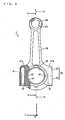
- Fig. 1 is a perspective view of a split connecting rod before fracture separation according to a first preferred embodiment.
- Fig. 2 is an elevation view of the split connecting rod of Fig. 1 .
- Fig. 3(a) is a cross-section view of the split connecting rod of Fig. 2 along the line IV-IV, and
- Fig. 3(b) is a cross-section view of the split connecting rod of Fig. 2 along the line V-V.
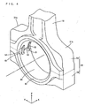
- Fig. 4 is a perspective view of the partially enlarged split connecting rod of Fig. 1 .
- the split connecting rod 1 preferably includes a rod body 10, a small end 20, and a large end 30.
- the rod body 10 has the small end 20 integrally formed at its one end, and the large end 30 integrally formed at its other end, so as to form a single unitary member.
- a substantially cylindrical piston pin opening 25 is formed in the small end 20.
- a substantially cylindrical crank pin opening 35 is formed in an approximately central portion of the large end 30.
- the large end 30 has shoulders 31a, 31b extending from the rod body 10 over the sides thereof.
- the shoulders 31a, 31b are provided with bolt holes 32 on both sides of the crank pin opening 35, respectively, extending from the lower surface of the large end 30 near the upper surface thereof.
- the direction in which the rod body 10 extends will hereinafter be referred to as a longitudinal direction
- the direction of the central axis of the crank pin opening 35 as shown by the dashed line in Fig. 4 will be simply referred to as an axial direction
- the direction that is perpendicular to the longitudinal and axial directions will be referred to as a width direction.
- the longitudinal direction is represented by the arrow Z
- the axial direction is represented by the arrow X
- the width direction is represented by the arrow Y.
- the large end 30 before fracture separation includes a rod 33 and cap 34 already formed integrally therewith.
- the rod 33 and cap 34 of the large end 30 are fractured and separated along a plane A to be fractured in parallel with the axial direction X and width direction Y.
- the plane A to be fractured is arranged to pass the central axis of the crank pin opening 35. That is, the plane A to be fractured intersects with the inner surface of the crank pin opening 35.
- Fracture start grooves 50 are formed to extend in the axial direction X at the centers of respective opposing positions on the inner surface of the crank pin opening 35.
- the fracture start grooves 50 are located at the centers of the lines where the inner surface of the crank pin opening 35 and the plane A to be fractured intersect with each other.
- Bearing securing grooves 51 are preferably formed on either or both of the opposing positions on the inner surface of the crank pin opening 35 for securing a bearing metal that functions as a bearing.
- the bearing securing grooves 51 prevent revolution of the bearing metal.
- the bearing securing grooves 51 are arranged to extend, respectively, across the fracture start groove 50 on the one side of the inner surface of the crank pin opening 35, as shown in Fig. 3(a) , with no bearing securing groove 51 formed on the other side, as shown in Fig. 3(b) .
- Each of the bearing securing grooves 51 is preferably defined by a recess having a curved bottom surface and is arranged to extend in the circumferential direction of the crank pin opening 35.
- the bottom surface of each of the bearing securing grooves 51 preferably bends in the form of an arc along the cross section that is substantially perpendicular to the axial direction X.
- notches 52 are provided, respectively, on both ends of each of the opposing positions on the inner surface of the crank pin opening 35 in the axial direction X.
- the notches 52 are preferably formed, respectively, on the sides of the bearing securing grooves 51 on the one side of the inner surface of the crank pin opening 35, and as shown in Fig. 3(b) , the notches 52 are preferably formed, respectively, to extend across the fracture start groove 50 on the other side of the inner surface of the crank pin opening 35.
- Each of the notches 52 having the curved bottom surface is arranged to extend in the circumferential direction of the crank pin opening 35.
- the bottom surface of each of the notches 52 preferably bends in the form of an arc along the cross section substantially perpendicular to the axial direction X.
- chamfers 53 formed by chamfering the edges of the crank pin opening 35 are provided, respectively, and are arranged to extend in the circumferential direction of the crank pin opening 35.
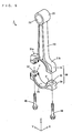
- Fig. 5 is a perspective view of the assembly of the split connecting rod according to the first preferred embodiment.
- Fig. 6 is a perspective view of the partially enlarged split connecting rod of Fig. 5 .
- the rod 33 and the cap 34 defining the large end 30 of the split connecting rod 1 are fractured and separated along the fracture start grooves 50. This results in the formation of fracture planes F on the rod 33 and the cap 34, respectively, as shown in Figs. 5 and 6 .
- the fracture planes F have fine irregularities.
- the fracture planes F on the rod 33 and on the cap 34 are arranged to come into contact with each other.
- Bolts 40 are threaded into bolt holes 32 such that the rod 33 and cap 34 are joined to each other. Since the fracture planes F on the rod 33 and on the cap 34 have the fine irregularities that are complementary to each other, the rod 33 and the cap 34 can be accurately positioned relative to each other.
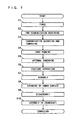
- FIG. 7 is a flowchart showing the method of manufacturing the split connecting rod according to the present preferred embodiment.
- a blank body of the connecting rod 1 including the rod body 10, the small end 20, and the large end 30 is formed preferably by forging (Step S1).
- the rod 33 and the cap 34 are formed integrally with the large end 30.
- the connecting rod 1 may be formed by casting or sintering or other suitable process.
- a steel containing carbon (C) is preferably used as a material of the connecting rod 1. It is preferable that the steel has a carbon content of about 0.05% to about 0.45% by weight, and more preferably about 0.10% to about 0.35% by weight, in a region where the carbon concentration is not increased due to carburization. This increases the toughness of the steel to improve the tolerance of the connecting rod 1.
- SCM 420 which is a chromium molybdenum steel, is preferably used as an example of the material for the connecting rod 1.
- the SCM 420 includes about 0.18% to about 0.23% carbon (C) by weight, about 0.15% to about 0.35% silicon (Si) by weight, about 0.60% to about 0.85% manganese (Mn) by weight, about 0.030% or less phosphor (P) by weight, about 0.030% or less sulfur (S) by weight, about 0.90% to about 1.20% chromium (Cr) by weight, and about 0.15% to about 0.30% molybdenum (Mo) by weight, for example.
- titanium (Ti) may be used as the material of the connecting rod 1.
- a carbon steel with a large content of carbon e.g., SAE 1070 may be used as the material of the connecting rod 1.
- Fig. 8 is a flowchart showing pre-carburization machining in detail.
- the pre-carburization machining involves first grinding of a thickness surface of the connecting rod 1, i.e., the surface normal to the axial direction X, (Step S21), and the formation of the piston pin opening 25 and crank pin opening 35 in the small end 20 and the large end 30, respectively (Step S22) .
- Step S23 the bearing securing grooves 51 are formed on the inner surface of the crank pin opening 35 of the large end 30 (Step S23), followed by the formation of the notches 52 on both sides of the bearing securing grooves 51 (Step S24) .
- the chamfers 53 are then formed at the edges of the crank pin opening 35 (Step S25), followed by the formation of the bolt holes 32 in the shoulders 31a, 31b of the connecting rod 1, respectively (Step S26).
- piston pin opening 25, crank pin opening 35, bearing securing grooves 51, notches 52, chamfers 53, and bolt holes 32 is preferably done by cutting.
- the fracture start grooves 50 are formed on the inner surface of the crank pin opening 35 (Step S27).
- the fracture start grooves 50 are preferably formed by a wire-cut EDM (Electrical Discharge Machining).
- the wire-cut EDM involves the arrangement of an electrically conducting wire on the inner surface of the crank pin opening 35 along the axial direction X, and the application of a pulsed high voltage between the conducting wire and the inner surface of the crank pin opening 35. This causes a corona discharge between the conducting wire and the inner surface of the crank pin opening 35, thereby linearly cutting away the inner surface of the crank pin opening 35 except the bearing securing grooves 51, notches 52, and chamfers 53. As a result, the fracture start grooves 50 that linearly extend in the axial direction X are formed at the centers of the inner surface of the crank pin opening 35.
- the wire-cut EDM allows for simultaneous formation of fracture start grooves 50 in a plurality of connecting rods 1. This results in improved productivity.
- fracture start grooves 50 may be formed by other machining methods, such as laser machining or cutting or other suitable processes.
- the grinding of the thickness surface of the connecting rod 1, formation of the piston pin opening 25 and crank pin opening 35, formation of the bearing securing grooves 51, formation of the notches 52, formation of the chamfers 53, formation of the bolt holes 32, and formation of the fracture start grooves 50 may be performed in any sequence other than that of Fig. 8 .
- the bearing securing grooves 51, notches 52, and chamfers 53 may be formed after the formation of the fracture start grooves 50.
- a surface hardening process i.e., carburization, quenching, and tempering, is performed over the entire connecting rod 1 (Step S3 of Fig. 7 ). This results in the formation of a surface hardened layer extending over an entire surface of the connecting rod 1.
- the resultant depth of carburization is approximately 1.0 mm, for example.
- Step S4 a shot peening process is applied to the connecting rod 1 (Step S4), and then the bolt holes 32 of the large end 30 are internally threaded (Step S5).
- the large end 30 of the connecting rod 1 is then fractured and separated into the rod 33 and cap 34 (Step S6).
- Fig. 9 is a schematic cross-section view illustrating a method of fracture separation.
- the connecting rod 1 is preferably cooled with liquid nitrogen in advance.
- projections of sliders 200, 201 that are horizontally movable relative to each other are inserted into the crank pin opening 35 of the large end 30 of the connecting rod 1, and a wedge 202 is hammered into the gap between the projections of the sliders 200, 201 with a weight 203. This causes the large end 30 of the connecting rod 1 to be fractured and separated into the rod 33 and the cap 34 along the fracture start grooves 50.
- Step S8 the inner surfaces of the piston pin opening 25 of the small end 20 and the crank pin opening 35 of the large end 30 of the assembled connecting rod 1 are grinded.
- the nutless type split connecting rod 1 is manufactured.
- the rod 33 and the cap 34 are subsequently disassembled by removing the bolts 40 from the large end 30 of the assembled connecting rod 1 (Step S9). Lastly, the disassembled rod 33 and cap 34 are assembled into the crank pin of the crankshaft (Step S10).
- Fig. 10(a) is a cross-section view showing the shape of the fracture start groove 50
- Fig. 10(b) is a cross-section view showing the shape of the notch 52
- Fig. 10(c) is a cross-section view showing the shape of the bearing securing groove 51.
- the fracture start groove 50 preferably includes opposing surfaces arranged substantially in parallel with each other and a semicircular bottom surface.
- the depth H1 of the fracture start groove 50 is, for example, about 0.5 mm, and the radius of the curvature R1 of the bottom surface is, for example, about 0.1 mm.
- the notch 52 preferably includes an arc-shaped bottom surface.
- the depth H2 of the notch 52 is, for example, about 0.5 mm, and the radius of the curvature R2 of the bottom surface is, for example, about 6.5 mm.
- the bearing securing groove 51 preferably includes an arc-shaped bottom surface.
- the depth H3 of the bearing securing groove 51 is, for example, about 1.6 mm, and the radius of the curvature R3 of the bottom surface is, for example, about 6.5 mm.
- the depth H2 of the notch 52 and the depth H3 of the bearing securing groove 51 are equal to or greater than the depth H1 of the fracture start groove 50.
- the depth H2 of the notch 52 is preferably almost equal to the depth H1 of the fracture start groove 50, the depth H3 of the bearing securing groove 51 being greater than the depth H1 of the fracture start groove 50.
- the radius of the curvature R2 of the bottom surface of the notch 52 is greater than the radius of the curvature R1 of the bottom surface of the fracture start groove 50, the radius of the curvature R3 of the bottom surface of the bearing securing groove 51 being greater than the radius of the curvature R1 of the fracture start groove 50.
- the stress concentration factor ⁇ is about 5.5 according to the above equation (1).
- the stress concentration factor ⁇ is about 1.6 according to the above equation (1).
- the stress concentration factor ⁇ is about 2.0 according to the above equation (1).
- the stress concentration factor of the fracture start groove 50 is greater than those of the notch 52 and bearing securing groove 51.
- SCM 420 which is a chromium molybdenum steel, was used as the material of the connecting rod 1.
- a surface hardened layer of the SCM 420 after carburization, quenching, and tempering has a carbon content of about 0.7% to about 0.8% by weight and a Charpy impact value of about 7 J/cm 2 to about 12 J/cm 2 .
- the inside of the SCM 420 after carburization, quenching, and tempering has a carbon content of about 0.18% to about 0.23% by weight, and a Charpy impact value of about 60 J/cm 2 to about 70 J/cm 2 . This improves the toughness of the inside of the connecting rod 1.
- SAE 1070 (equivalent of the JIS S70C) used as the material for the conventional split connecting rod has a carbon content of 0.65% to 0.75% by weight, and a Charpy impact value of 20 J/cm 2 to 26 J/cm 2 .
- Fig. 11 is a diagram illustrating the fracture advance along a plane to be fractured for the large end in the comparative example
- Fig. 12 is a diagram showing the condition of the fracture plane for the large end in the comparative example
- Fig. 13 is an enlarged view of the area C of Fig. 12
- Fig. 14 is a cross-section view showing the steps of fracturing the large end to grinding the inner surface in the comparative example.
- a pair of bearing securing grooves 51 are provided on the inner surface of the crank pin opening 35 of the large end 30, where fracture start grooves 50 are formed between and both ends of the pair of bearing securing grooves 51, respectively.
- the fracture starts from the three points of the fracture start grooves 50 at the center and both ends of the inner surface of the crank pin opening 35.
- the fracture advances from the three points, i.e., the center and both ends of the inner surface of the crank pin opening 35, as shown by the arrows of Fig. 11 .
- crank pin opening 35 is grinded to the line D-D in a subsequent step, as shown in Fig. 13 .
- the conventional manufacturing method for the split connecting rod further involves the chamfering of an edge of the crank pin opening 35 to the line E-E, in a subsequent step after the fracture separation.
- Fig. 15 is a diagram illustrating fracture advance along a plane to be fractured for the large end in the example
- Fig. 16 is a diagram showing the condition of the fracture plane for the large end in the example
- Fig. 17 is a cross-section view showing the steps of fracturing the large end to grinding the inner surface in the example.
- the inner surface of the crank pin opening 35 of the large end 30 is sectioned by a pair of bearing securing grooves 51 into three parts including the approximate center, the two ends and the edges of the crank pin opening.
- a fracture start groove 50 is formed at the approximate center, notches 52 are formed on both ends, and chamfers 53 are formed at the edges of the crank pin opening 35.
- the fracture starts from the single point at the approximate center of the inner surface of the crank pin opening 35.
- the fracture advances from the single point at the approximate center of the inner surface of the crank pin opening 35, as shown by the arrows of Fig. 15 .
- a fracture plane F is formed by the fracture from the approximate center of the inner surface of the crank pin opening 35.
- the rod 33 and the cap 34 are fractured and separated along the single fracture plane F, which prevents the formation of double cracks.
- the fracture starts from the single point on the inner surface of the crank pin opening 35 upon fracture separation of the large end 30, so that the fracture advances from the single point at the approximate center of the inner surface of the crank pin opening 35.
- This causes the large end 30 to be fractured and separated into the rod 33 and the cap 34 along the single fracture plane F, thereby preventing the formation of double cracks.
- This prevents the formation of a sizable projection on the fracture plane F and the falling of a broken piece from the fracture plane F.
- the assembly of the rod 33 and the cap 34 of the large end thus results in a high degree of roundness and cylindricality while achieving a significant a decrease in the percentage of defective products.
- the fracture separation of the large end 30 of the split connecting rod 1 can be performed using the simple jig shown in Fig. 9 without requiring costly equipment. Therefore, the manufacturing cost of the split connecting rod 1 is reduced. Moreover, the use of a very tough material improves the tolerance of the split connecting rod 1.
- crank pin opening 35 preferably corresponds to an opening of a large end or a first opening
- piston pin opening 25 corresponds to a second opening
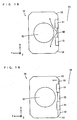
- Fig. 18 is a schematic diagram showing fracture advance along a plane to be fractured for a split connecting rod having not all the features of the present invention.
- the inner surface of the crank pin opening 35 of the large end 30 is sectioned by a pair of bearing securing grooves 51 into three parts: a fracture start groove 50 is formed on the approximate center, chamfers 53 are formed at the edges of the crank pin opening 35, with both sides of the bearing securing grooves 51 remaining flat without the formation of any fracture start grooves 50 and notches 52.
- the fracture start groove 50 is preferably formed by laser machining, cutting or other suitable processes.
- the stress concentration factor of the flat surface is smaller than that of the fracture start groove 50, so that the stress concentration on both ends of the inner surface of the crank pin opening 35 is alleviated and minimized.
- the formation of the chamfers 53 at the edges of the crank pin opening 35 alleviates and minimizes stress concentration at the edges of the crank pin opening 35. This results in the concentration of stress at the approximate center of the inner surface of the crank pin opening 35.
- the fracture starts from the single point at the approximate center of the inner surface of the crank pin opening 35.
- the fracture advances from the single point at the approximate center of the inner surface of the crank pin opening 35, as shown by the arrows of Fig. 18 .
- a fracture plane is formed by the fracture from the approximate center of the inner surface of the crank pin opening 35. This causes the large end 30 to be fractured and separated into the rod 33 and the cap 34 along the single fracture plane, thereby preventing the formation of double cracks.
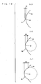
- Fig. 19 is a schematic diagram showing fracture advance along a plane to be fractured for a split connecting rod according to a third preferred embodiment.
- the inner surface of the crank pin opening 35 of the large end 30 is sectioned by a pair of bearing securing grooves 51 into three parts: a fracture start groove 50 is formed on one end, notches 52 are formed on the approximate center and the other end, and chamfers 53 are formed at the edges of the crank pin opening 35.
- the fracture start groove 50 is formed by laser machining, cutting, or other suitable processes.
- the fracture starts from the single point at the one end of the inner surface of the crank pin opening 35.
- the fracture advances from the single point at the one end of the inner surface of the crank pin opening 35, as shown by the arrow of Fig. 19 .
- a fracture plane is formed by the fracture from the one end of the inner surface of the crank pin opening 35. This causes the large end 30 to be fractured and separated into the rod 33 and the cap 34 along the single fracture plane, thereby preventing the formation of double cracks.
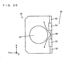
- Fig. 20 is a schematic diagram showing fracture advance along a plane to be fractured for a split connecting rod according to a fourth preferred embodiment.
- the inner surface of the crank pin opening 35 of the large end 30 is sectioned by a pair of bearing securing grooves 51 into three parts: a fracture start groove 50 is formed on the approximate center, and notches are formed on both ends of the crank pin opening 35.
- the crank pin opening 35 is not provided with chamfers 53 at its edges.
- the stress concentration factor of the notches 52 is smaller than that of the fracture start groove 50, so that the stress concentration at both ends of the inner surface of the crank pin opening 35 is alleviated and minimized. This results in the concentration of stress at the approximate center of the inner surface of the crank pin opening 35.
- the fracture starts from the single point at the approximate center of the inner surface of the crank pin opening 35.
- the fracture advances from the single point at the approximate center of the inner surface of the crank pin opening 35, as shown by the arrows of Fig. 20 .
- a fracture plane is formed by the fracture from the approximate center of the inner surface of the crank pin opening 35. This causes the large end 30 to be fractured and separated into the rod 33 and the cap 34 along the single fracture plane, thereby preventing the formation of double cracks.
- the bearing securing grooves 51 do not necessarily have to be formed in the structures of Figs. 15 , 18 , 19 , and 20 .
- the chamfers 53 do not necessarily have to be formed in the structures of Figs. 15 , 18, and 19 .
- a single bearing securing groove 51 may be formed on either or both the opposing positions on the inner surface of the crank pin opening 35, or three or more bearing securing grooves 51 may be formed thereon.
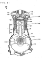
- Fig. 21 is a cross-section view showing an example of an engine including the slit connecting rod 1 according to a preferred embodiment.
- the engine 100 of Fig. 21 includes a crankcase 110, a cylinder block 120, and a cylinder head 130.
- the crankcase 110 is provided with a crankshaft 111.
- the crankshaft 111 includes a crank pin 112 and a crankweb 113.
- the cylinder block 120 is disposed above the crankcase 110.
- a cylindrical cylinder sleeve 121 where a piston 122 is reciprocatingly arranged in the axial direction, is mounted in the cylinder block 120.
- the piston 122 has a piston pin 123.
- the piston pin 123 is inserted into the piston pin opening of the small end 20 of the split connecting rod 1.
- a crank pin 112 is inserted into the crank pin opening of the large end 30 of the split connecting rod 1 with a bearing metal 114 therebetween.
- the piston pin 123 and crank pin 112 are thus coupled to each other.
- the bearing metal 114 is secured in the bearing securing grooves 51 of Figs. 1 to Fig. 4 .
- a cylinder head 130 is disposed above the cylinder block 120.
- the cylinder block 120 and cylinder head 130 together define a combustion chamber 131.
- An intake port 132 and an exhaust port 133 are formed in the cylinder head 130.
- the intake port 132 has an intake valve 134 that is arranged to be openable at its lower-end opening, whereas the exhaust port 133 has an exhaust valve 135 that is openable at its lower-end opening.
- the crank pin opening 35 of the split connecting rod 1 has a high degree of roundness and cylindricality, so that friction losses are decreased, while seizing up of the engine is prevented. Moreover, upon assembly of the split connecting rod 1 into the engine, the damage to the engine parts due to pieces of broken metal is prevented. Thus, a high-performance, low-cost engine 100 is provided. Furthermore, the use of a very tough material for the split connecting rod 1 improves the engine 100 in tolerance.
- Fig. 22 is a schematic view of a motorcycle including the engine 100 of Fig. 21 .
- a body frame 301 is provided with a head pipe 302 at its front end.
- the head pipe 302 is provided with a front fork 303 that can swing left and right.
- a front wheel 304 At the lower end of the front fork 303 is a front wheel 304 that is rotatably supported thereon.
- a handle 305 is mounted at the upper end of the head pipe 302.
- a seat rail 306 is mounted to extend rearwardly from the upstream of the lower end of the body frame 301.
- a fuel tank 307 is provided above the body frame 301.
- a main seat 308a and a tandem seat 308b are provided on the seat rail 306.
- a rear arm 309 is mounted to extend rearwardly from the rear end of the body frame 301.
- a rear wheel 310 is rotatably supported at the rear end of the rear arm 309.
- the engine 100 of Fig. 21 is preferably held in the approximate center of the body frame 301.
- the engine 100 includes the split connecting rod 1 according to a preferred embodiment described above.
- a radiator 311 is mounted on the front side of the engine 100.
- the exhaust port of the engine 100 is connected with an exhaust pipe 312, which is in turn mounted to the muffler 313 at its rear end.
- the engine 1 is coupled to a transmission 315.
- a drive sprocket 317 is mounted around a drive shaft 316 of the transmission 315.
- the drive sprocket 317 is coupled via a chain 318 to a rear-wheel sprocket 319 of a rear wheel 310.
- the transmission 315 and the chain 318 correspond to a transmission mechanism.
- the motorcycle of Fig. 22 includes the engine 100 of Fig. 21 so as to offer reduced cost, higher performance, and improved tolerance.
- split connecting rod 1 according to a preferred embodiment described above and the engine 100 including the same may find applications in various vehicles other than a motorcycle, such as a four-wheel car.
Abstract
Description
- The present invention relates to a split connecting rod and a method of manufacturing a split connecting rod. In particular, the present invention relates to a split connecting rod that joins a piston pin and a crank pin, an engine, including such a split connecting rod, and a vehicle including such an engine and split connecting rod.
- An engine for a car, motorcycle or other motorized vehicle uses a connecting rod that joins a piston pin and a crank pin. The connecting rod has a small end for rotatably holding a piston pin at one end of a rod body, and a large end for rotatably holding a crank pin at another end thereof. A piston pin opening into which the piston pin is inserted is formed in the small end, and a crank pin opening into which the crank pin is inserted is formed in the large end.
- A split connecting rod has its large end split in advance between a cap and a rod along a split plane including the axial center of the crank pin opening. The large end with the crank pin opening is formed by joining the rod and the cap with bolts.
- Such a split connecting rod requires accurate positioning of the cap and the rod upon assembly into a crankshaft, in order to maintain the crank pin opening of the large end in the shape of a perfect circle and cylinder.
- Among attempted solutions for improving the positioning accuracy is a fracture technique. The fracture technique involves the integral formation of a large end, and subsequent fracture separation of the large end into a rod and a cap. Since the fracture planes of the rod and the fracture planes of the cap have fine irregularities, accurate positioning of the rod and the cap is achieved by mating the fracture planes of the rod and the cap.
-
U.S. Patent No. 4,569,109 proposed the formation of fracture start grooves that extend linearly in the axial direction on the inner surface of a crank pin opening, in order to induce a fracture prior to the fracture separation of a large end into a rod and a cap. - According to the above-described fracture technique, the shape of fracture planes affects the accuracy of positioning the rod and the cap. In the presence of a plurality of fracture start points, in particular, different fracture planes may develop from the respective fracture start points. In this specification, the formation of different fracture planes will be called double cracking.
- Joining of the respective ends of different fracture planes causes a difference in level at the junction portion, resulting in the formation of a sizable projection on the fracture planes. This projection causes a resultant crank pin opening to have a shape that is less than a perfect circle and cylinder upon assembly of the rod and the cap. Further, metal between different fracture planes may fall off as broken pieces, which can cause damage to the engine parts.
- In recent years, a connecting rod having sufficient tolerance is needed for improving the tolerance of an engine. However, the use of a very tough material for a connecting rod to achieve improved tolerance often results in the formation of double cracks. For this reason, a carbon steel containing a large amount of carbon is usually used as the material of a connecting rod.
-
WO 99/06170 - The apparatus for fracture separation, however, has a complicated structure that requires precision in the jig used for the apparatus. This increases the equipment cost, while also presenting a burden of managing deterioration with time in the jig. As a result, the manufacturing cost of a split connecting rod is increased.
- In
US 6312159 B1 , considered as closest prior art, a split connecting rod is disclosed having a recessed groove with a V-shaped cross-section. Said recessed groove is formed in the inner peripheral surface of the large end of the split connecting rod and connects two locking grooves which are arranged at both outer sides of the large end. -
US 5507093 discloses a forged-steel connecting rod having a crevice, which is formed on the inner surface of the opening of the large end at one end or at both ends in an axial direction of said opening. - It is an objective of the present invention to provide a high-precision split connecting rod and a method of manufacturing a high-precision split connecting rod.
- According to an apparatus aspect of the present invention, said objective is solved by a split connecting rod having the combination of features of
independent claim 1. - In the manufacture of the split connecting rod, on each of the opposing positions on the inner surface of the opening, the fracture start groove is formed at the one portion of the line extending along the axial direction of the opening to have a greater stress concentration than the other portion of the line extending along the axial direction of the opening. The fracture separation of the large end occurs along each of the fracture start grooves.
- The fracture then starts from a single point on each of the lines on the inner surface, advancing from each of the single points on the inner surface of the opening. This causes the large end to be separated by the fracture separation along single fracture planes, thereby preventing the formation of double cracks. This prevents the formation of a sizable projection on each of the fracture planes, and also prevents falling of a broken piece therefrom. The assembly of the separated portions of the large end thus results in a high degree of roundness and cylindricality while achieving a significant decrease in the percentage of defective products.
- In addition, the large end of the split connecting rod can be separated by fracture separation using a simple jig without requiring the use of costly equipment. Therefore, the manufacturing cost of the split connecting rod is decreased. Furthermore, the use of a very tough material is possible and improves the tolerance of the split connecting rod.
- With the stress concentration factor of the notch being smaller than that of the fracture start groove, stress is concentrated at the fracture start groove, so that the stress concentration at the notch is alleviated and minimized. This results in the concentration of stress at the one portion of the line extending along the axial direction on the inner surface of the opening. The fracture thus advances from the single point on each of the opposing positions on the inner surface of the opening.
- With the stress concentration factor of the bearing securing grooves being smaller than that of the fracture start grove, stress is concentrated at the fracture start groove, so that the stress concentration at the one or more bearing securing grooves is alleviated and minimized. This results in the concentration of stress at the one portion of the line that extends along the axial direction on the inner surface of the opening. The fracture thus advances from the single point on each of the opposing positions on the inner surface of the opening. Preferably, the fracture start groove may be formed at an approximate center of each line along the axial direction on the inner surface of the opening.
- In this case, a fracture plane is formed by the fracture separation from the approximate center of the inner surface of the opening. This causes the large end to be separated by the fracture separation along the single fracture planes, thereby preventing the formation of double cracks.
- Preferably, the fracture start groove may also be formed at one end of each line that extends along the axial direction on the inner surface of the opening.
- In this case, a fracture plane is formed by the fracture separation from the one end of the inner surface of the opening. This causes the large end to be separated by the fracture separation along the single fracture planes, thereby preventing the formation of double cracks.
- Preferably, the Inside of the rod body and the large end are preferably made of a steel having a carbon content of not less than about 0.05 wt% and not more than about 0.45 wt%, such that a surface layer of the rod body and the large end has a carbon content that is higher than the inside thereof.
- In this case, the inside of the rod body and large end has significantly increased toughness, while the surface layer of the rod body and large end has significantly increased hardness. This improves the tolerance of the split connecting rod.
- According to a method aspect of the present invention, the aforementioned objective is solved by a method having the combination of features of
independent claim 8. - In the manufacturing method, the connecting rod including the rod body and the large end is formed first. Secondly, on each of the opposing positions on the inner surface of the opening, the fracture start groove is formed at the one portion of the line extending along the axial direction of the opening to have a greater stress concentration factor than the other portion. After this, the large end is separated by the fracture separation along the fracture start groove.
- The fracture then starts from the single point on each of the lines on the inner surface, advancing from each of the single points on the inner surface of the opening. This causes the large end to be separated by the fracture separation along single fracture planes, thereby preventing the formation of double cracks. This accordingly prevents the formation of a sizable projection on each of the fracture planes, and prevents falling of a broken piece therefrom. The assembly of the separated portions of the large end thus results in a high degree of roundness and cylindricality, while also achieving a significant decrease in the percentage of defective products.
- In addition, the large end of the split connecting rod can be separated by fracture separation using a simple jig without requiring the use of costly equipment. Therefore, the manufacturing cost of the split connecting rod is decreased. Furthermore, the use of a very tough material is possible and improves the tolerance of the split connecting rod.
- With the stress concentration factor of the notch being smaller than that of the fracture start groove, stress is concentrated at the fracture start groove, so that the stress concentration at the notch is alleviated and minimized. This results in the concentration of stress at the one portion of the line that extends along the axial direction on the inner surface of the opening. The fracture thus advances from the single point on each of the opposing positions on the inner surface of the opening.
- With the stress concentration factor of the bearing securing grooves being smaller than that of the fracture start grove, stress is concentrated at the fracture start groove, so that the stress concentration at the one or more bearing securing grooves is alleviated and minimized. This results in the concentration of stress at the one portion of the line that extends along the axial direction on the inner surface of the opening. The fracture thus advances from the single point on each of the opposing positions on the inner surface of the opening.
- Preferably, the step of forming the fracture start groove may include the step of forming the fracture start groove at an approximate center of each line that extends along the axial diretion on the inner surface of the opening.
- In this case, a fracture plane is formed by the fracture separation from the approximate center of the inner surface of the opening. This causes the large end to be separated by the fracture separation along the single fracture planes, thereby preventing the formation of double cracks.
- Preferably, the step of forming the fracture start groove also may include the step of forming the fracture start groove at one end of each line that extends along the axial direction on the inner surface of the opening.
- In this case, a fracture plane is formed by the fracture separation from the one end of the inner surface of the opening. This causes the large end to be separated by the fracture separation along the single fracture planes, thereby preventing the formation of double cracks.
- Preferably, the step of forming the rod body and the large end may include the step of forming the rod body and the large end of a steel having a carbon content of not less than about 0.05 wt% and not more than about 0.45 wt%.
- In this case, the inside of the rod body and large end has greatly increased toughness, which improves the tolerance of the split connecting rod.
- Preferably, the step of forming the rod body and the large end may further include the step of performing a surface hardening process so that a surface layer of the rod body and the large end has a carbon content that is greater than the inside thereof.
- In this case, the inside of the rod body and large end has greatly increased toughness, while the surface layer of the rod body and large end has greatly increased hardness. This further improves the tolerance of the split connecting rod.
- Preferably, the step of forming the fracture start groove may include the step of forming the fracture start groove by a wire-cut electrical discharge machining.
- In this case, simultaneous formation of fracture start grooves on the large ends of a plurality of connecting rods is possible. This improves the productivity.
- Further preferred embodiments of the present invention are laid down in the further subclaims.
- In the following, the present invention is explained in greater detail by means of several embodiments thereof in conjunction with the accompanying drawings, wherein:
-
Fig. 1 is a perspective view of a split connecting rod before fracture separation according to a first preferred embodiment; -
Fig. 2 is an elevation view of the split connecting rod ofFig. 1 ; -
Fig. 3(a) is a cross-section view of the split connecting rod ofFig. 2 along the line IV-IV, andFig. 3(b) is a cross-section view of the split connecting rod ofFig. 2 along the line V-V; -
Fig. 4 is a perspective view of the partially enlarged split connecting rod ofFig. 1 ; -
Fig. 5 is a perspective view of the assembly of the split connecting rod according to the first preferred embodiment; -
Fig. 6 is a perspective view of the partially enlarged split connecting rod ofFig. 5 ; -
Fig. 7 is a flowchart showing a method of manufacturing the split connecting rod according to a preferred embodiment; -
Fig. 8 is a flowchart showing pre-carburization machining in detail; -
Fig. 9 is a schematic cross-section view illustrating a method of fracture separation; -
Fig. 10(a) is a cross-section view showing the shape of a fracture start groove,Fig. 10(b) is a cross-section view showing the shape of a notch, andFig. 10(c) is a cross-section view showing the shape of a bearing securing groove. -
Fig. 11 is a diagram illustrating fracture advance along a plane to be fractured for the large end in a comparative example; -
Fig. 12 is a diagram showing the condition of the fracture plane for the large end in the comparative example; -
Fig. 13 is an enlarged view of the area C ofFig. 12 ; -
Fig. 14 is a cross-section view showing the steps of fracturing the large end to grinding the inner surface in the comparative example; -
Fig. 15 is a diagram illustrating fracture advance along a plane to be fractured for the large end in an example; -
Fig. 16 is a diagram showing the condition of the fracture plane for the large end in the example; -
Fig. 17 is a cross-section view showing the steps of fracturing the large end to grinding the inner surface in the example; -
Fig. 18 is a schematic diagram showing fracture advance along a plane to be fractured for a split connecting rod having not all the features of the present invention; -
Fig. 19 is a schematic diagram showing fracture advance along a plane to be fractured for a split connecting rod according to a third preferred embodiment; -
Fig. 20 is a schematic diagram showing fracture advance along a plane to be fractured for a split connecting rod according to a fourth preferred embodiment; -
Fig. 21 is a cross-section view showing an example of an engine using the split connecting rod according to the foregoing preferred embodiment; and -
Fig. 22 is a schematic view of an automatic motorcycle using the engine ofFig. 21 . -
Fig. 1 is a perspective view of a split connecting rod before fracture separation according to a first preferred embodiment.Fig. 2 is an elevation view of the split connecting rod ofFig. 1 .Fig. 3(a) is a cross-section view of the split connecting rod ofFig. 2 along the line IV-IV, andFig. 3(b) is a cross-section view of the split connecting rod ofFig. 2 along the line V-V.Fig. 4 is a perspective view of the partially enlarged split connecting rod ofFig. 1 . - As shown in
Figs. 1 ,2 ,3(a) and 3(b) , thesplit connecting rod 1 preferably includes arod body 10, asmall end 20, and alarge end 30. Therod body 10 has thesmall end 20 integrally formed at its one end, and thelarge end 30 integrally formed at its other end, so as to form a single unitary member. - A substantially cylindrical
piston pin opening 25 is formed in thesmall end 20. A substantially cylindrical crankpin opening 35 is formed in an approximately central portion of thelarge end 30. Thelarge end 30 hasshoulders rod body 10 over the sides thereof. Theshoulders crank pin opening 35, respectively, extending from the lower surface of thelarge end 30 near the upper surface thereof. - The direction in which the
rod body 10 extends will hereinafter be referred to as a longitudinal direction, the direction of the central axis of thecrank pin opening 35 as shown by the dashed line inFig. 4 will be simply referred to as an axial direction, and the direction that is perpendicular to the longitudinal and axial directions will be referred to as a width direction. InFigs. 1 to 6 andFigs. 11 to 20 described below, the longitudinal direction is represented by the arrow Z, the axial direction is represented by the arrow X, and the width direction is represented by the arrow Y. - The
large end 30 before fracture separation includes arod 33 andcap 34 already formed integrally therewith. As will be described later, therod 33 andcap 34 of thelarge end 30 are fractured and separated along a plane A to be fractured in parallel with the axial direction X and width direction Y. The plane A to be fractured is arranged to pass the central axis of thecrank pin opening 35. That is, the plane A to be fractured intersects with the inner surface of thecrank pin opening 35. - Fracture start
grooves 50 are formed to extend in the axial direction X at the centers of respective opposing positions on the inner surface of thecrank pin opening 35. The fracture startgrooves 50 are located at the centers of the lines where the inner surface of thecrank pin opening 35 and the plane A to be fractured intersect with each other. -
Bearing securing grooves 51 are preferably formed on either or both of the opposing positions on the inner surface of thecrank pin opening 35 for securing a bearing metal that functions as a bearing. Thebearing securing grooves 51 prevent revolution of the bearing metal. - In this preferred embodiment, the
bearing securing grooves 51 are arranged to extend, respectively, across the fracture startgroove 50 on the one side of the inner surface of thecrank pin opening 35, as shown inFig. 3(a) , with nobearing securing groove 51 formed on the other side, as shown inFig. 3(b) . - Each of the
bearing securing grooves 51 is preferably defined by a recess having a curved bottom surface and is arranged to extend in the circumferential direction of thecrank pin opening 35. The bottom surface of each of thebearing securing grooves 51 preferably bends in the form of an arc along the cross section that is substantially perpendicular to the axial direction X. - In addition,
notches 52 are provided, respectively, on both ends of each of the opposing positions on the inner surface of the crank pin opening 35 in the axial direction X. In the present preferred embodiment, as shown inFig. 3(a) , thenotches 52 are preferably formed, respectively, on the sides of thebearing securing grooves 51 on the one side of the inner surface of thecrank pin opening 35, and as shown inFig. 3(b) , thenotches 52 are preferably formed, respectively, to extend across the fracture startgroove 50 on the other side of the inner surface of thecrank pin opening 35. - Each of the
notches 52 having the curved bottom surface is arranged to extend in the circumferential direction of thecrank pin opening 35. The bottom surface of each of thenotches 52 preferably bends in the form of an arc along the cross section substantially perpendicular to the axial direction X. - In addition, chamfers 53 formed by chamfering the edges of the
crank pin opening 35 are provided, respectively, and are arranged to extend in the circumferential direction of thecrank pin opening 35. -
Fig. 5 is a perspective view of the assembly of the split connecting rod according to the first preferred embodiment.Fig. 6 is a perspective view of the partially enlarged split connecting rod ofFig. 5 . - The
rod 33 and thecap 34 defining thelarge end 30 of thesplit connecting rod 1 are fractured and separated along the fracture startgrooves 50. This results in the formation of fracture planes F on therod 33 and thecap 34, respectively, as shown inFigs. 5 and6 . The fracture planes F have fine irregularities. - The fracture planes F on the
rod 33 and on thecap 34 are arranged to come into contact with each other.Bolts 40 are threaded into bolt holes 32 such that therod 33 andcap 34 are joined to each other. Since the fracture planes F on therod 33 and on thecap 34 have the fine irregularities that are complementary to each other, therod 33 and thecap 34 can be accurately positioned relative to each other. - A method of manufacturing the split connecting rod according to a preferred embodiment will now be described.
Fig. 7 is a flowchart showing the method of manufacturing the split connecting rod according to the present preferred embodiment. - Initially, a blank body of the connecting
rod 1 including therod body 10, thesmall end 20, and thelarge end 30 is formed preferably by forging (Step S1). In this case, therod 33 and thecap 34 are formed integrally with thelarge end 30. Instead of forging, the connectingrod 1 may be formed by casting or sintering or other suitable process. - A steel containing carbon (C) is preferably used as a material of the connecting
rod 1. It is preferable that the steel has a carbon content of about 0.05% to about 0.45% by weight, and more preferably about 0.10% to about 0.35% by weight, in a region where the carbon concentration is not increased due to carburization. This increases the toughness of the steel to improve the tolerance of the connectingrod 1. - In this preferred embodiment, SCM 420, which is a chromium molybdenum steel, is preferably used as an example of the material for the connecting
rod 1. The SCM 420 includes about 0.18% to about 0.23% carbon (C) by weight, about 0.15% to about 0.35% silicon (Si) by weight, about 0.60% to about 0.85% manganese (Mn) by weight, about 0.030% or less phosphor (P) by weight, about 0.030% or less sulfur (S) by weight, about 0.90% to about 1.20% chromium (Cr) by weight, and about 0.15% to about 0.30% molybdenum (Mo) by weight, for example. - Alternatively, titanium (Ti) may be used as the material of the connecting
rod 1. Still alternatively, a carbon steel with a large content of carbon (e.g., SAE 1070) may be used as the material of the connectingrod 1. - The connecting
rod 1 is subsequently machined in preparation for carburization (Step S2).Fig. 8 is a flowchart showing pre-carburization machining in detail. The pre-carburization machining involves first grinding of a thickness surface of the connectingrod 1, i.e., the surface normal to the axial direction X, (Step S21), and the formation of thepiston pin opening 25 and crank pin opening 35 in thesmall end 20 and thelarge end 30, respectively (Step S22) . - Then, the
bearing securing grooves 51 are formed on the inner surface of the crank pin opening 35 of the large end 30 (Step S23), followed by the formation of thenotches 52 on both sides of the bearing securing grooves 51 (Step S24) . Thechamfers 53 are then formed at the edges of the crank pin opening 35 (Step S25), followed by the formation of the bolt holes 32 in theshoulders rod 1, respectively (Step S26). - The formation of the
piston pin opening 25, crankpin opening 35, bearing securinggrooves 51,notches 52, chamfers 53, and bolt holes 32 is preferably done by cutting. - After this, the fracture start
grooves 50 are formed on the inner surface of the crank pin opening 35 (Step S27). In this preferred embodiment, the fracture startgrooves 50 are preferably formed by a wire-cut EDM (Electrical Discharge Machining). - The wire-cut EDM involves the arrangement of an electrically conducting wire on the inner surface of the
crank pin opening 35 along the axial direction X, and the application of a pulsed high voltage between the conducting wire and the inner surface of thecrank pin opening 35. This causes a corona discharge between the conducting wire and the inner surface of thecrank pin opening 35, thereby linearly cutting away the inner surface of thecrank pin opening 35 except thebearing securing grooves 51,notches 52, and chamfers 53. As a result, the fracture startgrooves 50 that linearly extend in the axial direction X are formed at the centers of the inner surface of thecrank pin opening 35. - The wire-cut EDM allows for simultaneous formation of fracture start
grooves 50 in a plurality of connectingrods 1. This results in improved productivity. - Note that the fracture start
grooves 50 may be formed by other machining methods, such as laser machining or cutting or other suitable processes. - The grinding of the thickness surface of the connecting
rod 1, formation of thepiston pin opening 25 and crankpin opening 35, formation of thebearing securing grooves 51, formation of thenotches 52, formation of thechamfers 53, formation of the bolt holes 32, and formation of the fracture startgrooves 50 may be performed in any sequence other than that ofFig. 8 . - As an example, the
bearing securing grooves 51,notches 52, and chamfers 53 may be formed after the formation of the fracture startgrooves 50. - Then, a surface hardening process, i.e., carburization, quenching, and tempering, is performed over the entire connecting rod 1 (Step S3 of
Fig. 7 ). This results in the formation of a surface hardened layer extending over an entire surface of the connectingrod 1. The resultant depth of carburization is approximately 1.0 mm, for example. - Other surface hardening processes such as nitriding, spraying, vapor deposition, or high-frequency tempering may be adopted as an alternative.
- After this, a shot peening process is applied to the connecting rod 1 (Step S4), and then the bolt holes 32 of the
large end 30 are internally threaded (Step S5). - The
large end 30 of the connectingrod 1 is then fractured and separated into therod 33 and cap 34 (Step S6). -
Fig. 9 is a schematic cross-section view illustrating a method of fracture separation. The connectingrod 1 is preferably cooled with liquid nitrogen in advance. As shown inFig. 9 , projections ofsliders large end 30 of the connectingrod 1, and awedge 202 is hammered into the gap between the projections of thesliders weight 203. This causes thelarge end 30 of the connectingrod 1 to be fractured and separated into therod 33 and thecap 34 along the fracture startgrooves 50. - Following this, the
bolts 40 are screwed into the bolt holes 32, with the fracture planes F on therod 33 and thecap 34 being positioned to contact with each other as described above, so that therod 33 and thecap 34 are assembled (Step S7 ofFig. 7 ). - Then, the inner surfaces of the piston pin opening 25 of the
small end 20 and the crank pin opening 35 of thelarge end 30 of the assembled connectingrod 1 are grinded (Step S8). Thus, the nutless typesplit connecting rod 1 is manufactured. - The
rod 33 and thecap 34 are subsequently disassembled by removing thebolts 40 from thelarge end 30 of the assembled connecting rod 1 (Step S9). Lastly, the disassembledrod 33 andcap 34 are assembled into the crank pin of the crankshaft (Step S10). - Now, the shapes of the fracture start
grooves 50,notches 52, and bearing securinggrooves 51, and the stress concentration factors thereof will be described. -
Fig. 10(a) is a cross-section view showing the shape of the fracture startgroove 50;Fig. 10(b) is a cross-section view showing the shape of thenotch 52; andFig. 10(c) is a cross-section view showing the shape of thebearing securing groove 51. - As shown in
Fig. 10(a) , the fracture startgroove 50 preferably includes opposing surfaces arranged substantially in parallel with each other and a semicircular bottom surface. The depth H1 of the fracture startgroove 50 is, for example, about 0.5 mm, and the radius of the curvature R1 of the bottom surface is, for example, about 0.1 mm. - As shown in
Fig. 10(b) , thenotch 52 preferably includes an arc-shaped bottom surface. The depth H2 of thenotch 52 is, for example, about 0.5 mm, and the radius of the curvature R2 of the bottom surface is, for example, about 6.5 mm. - As shown in
Fig. 10(c) , thebearing securing groove 51 preferably includes an arc-shaped bottom surface. The depth H3 of thebearing securing groove 51 is, for example, about 1.6 mm, and the radius of the curvature R3 of the bottom surface is, for example, about 6.5 mm. - The depth H2 of the
notch 52 and the depth H3 of thebearing securing groove 51 are equal to or greater than the depth H1 of the fracture startgroove 50. In this preferred embodiment, the depth H2 of thenotch 52 is preferably almost equal to the depth H1 of the fracture startgroove 50, the depth H3 of thebearing securing groove 51 being greater than the depth H1 of the fracture startgroove 50. The radius of the curvature R2 of the bottom surface of thenotch 52 is greater than the radius of the curvature R1 of the bottom surface of the fracture startgroove 50, the radius of the curvature R3 of the bottom surface of thebearing securing groove 51 being greater than the radius of the curvature R1 of the fracture startgroove 50. - In general, the stress concentration factor α can be determined by the following equation:

where H represents the depth of the notch, and R represents the radius of the curvature thereof. - With the depth H1 of the fracture start
groove 50 of about 0.5 mm, and the radius of the curvature R1 of about 0.1, the stress concentration factor α is about 5.5 according to the above equation (1). - With the depth H2 of the
notch 52 of about 0.5 mm, and the radius of the curvature R2 of about 6.5 mm, the stress concentration factor α is about 1.6 according to the above equation (1). With the depth H3 of thebearing securing groove 51 of about 1.6 mm, and the radius of the curvature R3 of about 6. 5 mm, the stress concentration factor α is about 2.0 according to the above equation (1). - Thus, the stress concentration factor of the fracture start
groove 50 is greater than those of thenotch 52 andbearing securing groove 51. - This results in the concentration of stress at the fracture start
groove 50 on the inner surface of thecrank pin opening 35, thereby alleviating and minimizing stress concentration at thenotch 52 andbearing securing groove 51. This results in the concentration of stress at the center of the inner surface of thecrank pin opening 35. - In the following example and comparative example, the action of the fracture start
grooves 50 andnotches 52 during the fracture separation of thelarge end 30 was verified. In the example, a large end provided with thenotches 52 was separated by fracture separation, whereas in the comparative example, a large end without thenotches 52 was separated by fracture separation. The large end in the example is the same as thelarge end 30 ofFigs. 1 to 4 . - SCM 420, which is a chromium molybdenum steel, was used as the material of the connecting
rod 1. A surface hardened layer of the SCM 420 after carburization, quenching, and tempering, has a carbon content of about 0.7% to about 0.8% by weight and a Charpy impact value of about 7 J/cm2 to about 12 J/cm2. The inside of the SCM 420 after carburization, quenching, and tempering has a carbon content of about 0.18% to about 0.23% by weight, and a Charpy impact value of about 60 J/cm2 to about 70 J/cm2. This improves the toughness of the inside of the connectingrod 1. - Note that SAE 1070 (equivalent of the JIS S70C) used as the material for the conventional split connecting rod has a carbon content of 0.65% to 0.75% by weight, and a Charpy impact value of 20 J/cm2 to 26 J/cm2.
- With reference to
Figs. 11 to 14 , description is first made of fracture advance on the large end without notches in the comparative example, and then with reference toFigs. 15 to 17 , description is made of fracture advance on the large end with notches in the example. -
Fig. 11 is a diagram illustrating the fracture advance along a plane to be fractured for the large end in the comparative example;Fig. 12 is a diagram showing the condition of the fracture plane for the large end in the comparative example;Fig. 13 is an enlarged view of the area C ofFig. 12 ; andFig. 14 is a cross-section view showing the steps of fracturing the large end to grinding the inner surface in the comparative example. - In the comparative example of
Fig. 11 , a pair of bearing securinggrooves 51 are provided on the inner surface of the crank pin opening 35 of thelarge end 30, where fracture startgrooves 50 are formed between and both ends of the pair of bearing securinggrooves 51, respectively. - Stress in general tends to concentrate at thinner portions and end portions. With the
bolt hole 32 provided in the center of thelarge end 30, the center of the inner surface of thecrank pin opening 35 corresponds to the thinner portion. Thus, stresses are concentrated at the center and both ends of the inner surface of thecrank pin opening 35. - Accordingly, with the comparative example of
Fig. 11 , the fracture starts from the three points of the fracture startgrooves 50 at the center and both ends of the inner surface of thecrank pin opening 35. As a result, the fracture advances from the three points, i.e., the center and both ends of the inner surface of thecrank pin opening 35, as shown by the arrows ofFig. 11 . - In this case, as shown in
Figs. 12 and13 , when the fracture plane a formed by the fracture from the center of the inner surface of thecrank pin opening 35 and the fracture planes b formed by the fractures from the both ends develop at a different level, aregion 350 as shown inFig. 14(a) is formed where the fracture plane a and the fracture plane b overlap each other by a certain distance, resulting in the formation of double cracks. - Note that the inner surface of the
crank pin opening 35 is grinded to the line D-D in a subsequent step, as shown inFig. 13 . The conventional manufacturing method for the split connecting rod further involves the chamfering of an edge of the crank pin opening 35 to the line E-E, in a subsequent step after the fracture separation. - Next, as shown in
Fig. 14(b) , separation of therod 33 and thecap 34 causes a difference in level at a junction M of the fracture plane a and fracture plane b. As shown inFig. 12 , the junction M is closer to the crankpin opening 35 relative to the center line L1 of thelarge end 30 in the width direction Y. - Then, as shown in
Fig. 14(c) , after the assembly of therod 33 and thecap 34, the inner surface of thecrank pin opening 35 is grinded to the line D-D. Upon disassembly of therod 33 and thecap 34, abroken piece 341 falls off theregion 350, as shown inFig. 14(d) , where the fracture plane a and the fracture plane b overlap. -
Fig. 15 is a diagram illustrating fracture advance along a plane to be fractured for the large end in the example;Fig. 16 is a diagram showing the condition of the fracture plane for the large end in the example; andFig. 17 is a cross-section view showing the steps of fracturing the large end to grinding the inner surface in the example. - In the example of
Fig. 15 , the inner surface of the crank pin opening 35 of thelarge end 30 is sectioned by a pair of bearing securinggrooves 51 into three parts including the approximate center, the two ends and the edges of the crank pin opening. A fracture startgroove 50 is formed at the approximate center,notches 52 are formed on both ends, and chamfers 53 are formed at the edges of thecrank pin opening 35. - Since the stress concentration factor of the
notches 52 is smaller than that of the fracture startgroove 50, stress concentration is alleviated on both ends of thecrank pin opening 35. In addition, the formation of thechamfers 53 at the edges of thecrank pin opening 35 alleviates and minimizes stress concentration at the edges of thecrank pin opening 35. This results in the concentration of stress at the approximate center of the inner surface of thecrank pin opening 35. - Thus, in the example of
Fig. 15 , the fracture starts from the single point at the approximate center of the inner surface of thecrank pin opening 35. As a result, the fracture advances from the single point at the approximate center of the inner surface of thecrank pin opening 35, as shown by the arrows ofFig. 15 . - In this case, as shown in
Fig. 16 , a fracture plane F is formed by the fracture from the approximate center of the inner surface of thecrank pin opening 35. As shown inFig. 17(a) , therod 33 and thecap 34 are fractured and separated along the single fracture plane F, which prevents the formation of double cracks. - Accordingly, as shown in
Fig. 17(b) , upon separation of therod 33 and thecap 34, there is no difference in level on the fracture plane F. - Then, as shown in
Fig. 17(c) , after the assembly of therod 33 and thecap 34, the inner surface of thecrank pin opening 35 is grinded to the line D-D. As shown inFig. 17(d) , no broken piece falls off upon disassembly of therod 33 and thecap 34. - Thus, in the present preferred embodiment, there is no region where a plurality of fracture planes overlap between the center line L1 of the
large end 30 and the inner surface of the crank pin opening 35 in the width direction Y, as shown inFig. 16 . The elimination of such a region at least between the line L2 tangent to thebolt hole 32 in parallel with the axial direction X and the inner surface of thecrank pin opening 35 prevents a broken piece from falling off during the grinding of the inner surface of thecrank pin opening 35. - In the
split connecting rod 1 according to the present preferred embodiment, even with the use of a very tough material, the fracture starts from the single point on the inner surface of the crank pin opening 35 upon fracture separation of thelarge end 30, so that the fracture advances from the single point at the approximate center of the inner surface of thecrank pin opening 35. This causes thelarge end 30 to be fractured and separated into therod 33 and thecap 34 along the single fracture plane F, thereby preventing the formation of double cracks. This prevents the formation of a sizable projection on the fracture plane F and the falling of a broken piece from the fracture plane F. The assembly of therod 33 and thecap 34 of the large end thus results in a high degree of roundness and cylindricality while achieving a significant a decrease in the percentage of defective products. - In addition, the fracture separation of the
large end 30 of thesplit connecting rod 1 can be performed using the simple jig shown inFig. 9 without requiring costly equipment. Therefore, the manufacturing cost of thesplit connecting rod 1 is reduced. Moreover, the use of a very tough material improves the tolerance of thesplit connecting rod 1. - In the present preferred embodiment, the
crank pin opening 35 preferably corresponds to an opening of a large end or a first opening, and thepiston pin opening 25 corresponds to a second opening. -
Fig. 18 is a schematic diagram showing fracture advance along a plane to be fractured for a split connecting rod having not all the features of the present invention. - In the second preferred embodiment, the inner surface of the crank pin opening 35 of the
large end 30 is sectioned by a pair of bearing securinggrooves 51 into three parts: afracture start groove 50 is formed on the approximate center, chamfers 53 are formed at the edges of thecrank pin opening 35, with both sides of thebearing securing grooves 51 remaining flat without the formation of any fracture startgrooves 50 andnotches 52. The fracture startgroove 50 is preferably formed by laser machining, cutting or other suitable processes. - The stress concentration factor of the flat surface is smaller than that of the fracture start
groove 50, so that the stress concentration on both ends of the inner surface of thecrank pin opening 35 is alleviated and minimized. In addition, the formation of thechamfers 53 at the edges of thecrank pin opening 35 alleviates and minimizes stress concentration at the edges of thecrank pin opening 35. This results in the concentration of stress at the approximate center of the inner surface of thecrank pin opening 35. - Thus, the fracture starts from the single point at the approximate center of the inner surface of the
crank pin opening 35. As a result, the fracture advances from the single point at the approximate center of the inner surface of thecrank pin opening 35, as shown by the arrows ofFig. 18 . - In this case, a fracture plane is formed by the fracture from the approximate center of the inner surface of the
crank pin opening 35. This causes thelarge end 30 to be fractured and separated into therod 33 and thecap 34 along the single fracture plane, thereby preventing the formation of double cracks. -
Fig. 19 is a schematic diagram showing fracture advance along a plane to be fractured for a split connecting rod according to a third preferred embodiment. - In the third preferred embodiment, the inner surface of the crank pin opening 35 of the
large end 30 is sectioned by a pair of bearing securinggrooves 51 into three parts: afracture start groove 50 is formed on one end,notches 52 are formed on the approximate center and the other end, and chamfers 53 are formed at the edges of thecrank pin opening 35. The fracture startgroove 50 is formed by laser machining, cutting, or other suitable processes. - In this case, stress concentration is alleviated and minimized at the other end and the approximate center of the inner surface of the
crank pin opening 35. In addition, the formation of thechamfers 53 at the edges of thecrank pin opening 35 alleviates and minimizes stress concentration at the edges of thecrank pin opening 35. This results in the concentration of stress at the one end of the inner surface of thecrank pin opening 35. - Thus, the fracture starts from the single point at the one end of the inner surface of the
crank pin opening 35. As a result, the fracture advances from the single point at the one end of the inner surface of thecrank pin opening 35, as shown by the arrow ofFig. 19 . - In this case, a fracture plane is formed by the fracture from the one end of the inner surface of the
crank pin opening 35. This causes thelarge end 30 to be fractured and separated into therod 33 and thecap 34 along the single fracture plane, thereby preventing the formation of double cracks. -
Fig. 20 is a schematic diagram showing fracture advance along a plane to be fractured for a split connecting rod according to a fourth preferred embodiment. - In the fourth preferred embodiment, the inner surface of the crank pin opening 35 of the
large end 30 is sectioned by a pair of bearing securinggrooves 51 into three parts: afracture start groove 50 is formed on the approximate center, and notches are formed on both ends of thecrank pin opening 35. Thecrank pin opening 35 is not provided withchamfers 53 at its edges. - The stress concentration factor of the
notches 52 is smaller than that of the fracture startgroove 50, so that the stress concentration at both ends of the inner surface of thecrank pin opening 35 is alleviated and minimized. This results in the concentration of stress at the approximate center of the inner surface of thecrank pin opening 35. - Thus, the fracture starts from the single point at the approximate center of the inner surface of the
crank pin opening 35. As a result, the fracture advances from the single point at the approximate center of the inner surface of thecrank pin opening 35, as shown by the arrows ofFig. 20 . - In this case, a fracture plane is formed by the fracture from the approximate center of the inner surface of the
crank pin opening 35. This causes thelarge end 30 to be fractured and separated into therod 33 and thecap 34 along the single fracture plane, thereby preventing the formation of double cracks. - The
bearing securing grooves 51 do not necessarily have to be formed in the structures ofFigs. 15 ,18 ,19 , and20 . Thechamfers 53 do not necessarily have to be formed in the structures ofFigs. 15 ,18, and 19 . - Still alternatively, a single
bearing securing groove 51 may be formed on either or both the opposing positions on the inner surface of thecrank pin opening 35, or three or morebearing securing grooves 51 may be formed thereon. -
Fig. 21 is a cross-section view showing an example of an engine including theslit connecting rod 1 according to a preferred embodiment. - The
engine 100 ofFig. 21 includes acrankcase 110, acylinder block 120, and acylinder head 130. - The
crankcase 110 is provided with acrankshaft 111. Thecrankshaft 111 includes a crankpin 112 and acrankweb 113. - The
cylinder block 120 is disposed above thecrankcase 110. Acylindrical cylinder sleeve 121, where apiston 122 is reciprocatingly arranged in the axial direction, is mounted in thecylinder block 120. Thepiston 122 has apiston pin 123. - The
piston pin 123 is inserted into the piston pin opening of thesmall end 20 of thesplit connecting rod 1. Acrank pin 112 is inserted into the crank pin opening of thelarge end 30 of thesplit connecting rod 1 with a bearingmetal 114 therebetween. Thepiston pin 123 and crankpin 112 are thus coupled to each other. The bearingmetal 114 is secured in thebearing securing grooves 51 ofFigs. 1 to Fig. 4 . - A
cylinder head 130 is disposed above thecylinder block 120. Thecylinder block 120 andcylinder head 130 together define acombustion chamber 131. Anintake port 132 and anexhaust port 133 are formed in thecylinder head 130. Theintake port 132 has anintake valve 134 that is arranged to be openable at its lower-end opening, whereas theexhaust port 133 has an exhaust valve 135 that is openable at its lower-end opening. - In the
engine 100 ofFig. 21 , the crank pin opening 35 of thesplit connecting rod 1 according to a preferred embodiment described above has a high degree of roundness and cylindricality, so that friction losses are decreased, while seizing up of the engine is prevented. Moreover, upon assembly of thesplit connecting rod 1 into the engine, the damage to the engine parts due to pieces of broken metal is prevented. Thus, a high-performance, low-cost engine 100 is provided. Furthermore, the use of a very tough material for thesplit connecting rod 1 improves theengine 100 in tolerance. -
Fig. 22 is a schematic view of a motorcycle including theengine 100 ofFig. 21 . - In the
automatic motorcycle 100 ofFig. 22 , abody frame 301 is provided with ahead pipe 302 at its front end.. Thehead pipe 302 is provided with afront fork 303 that can swing left and right. At the lower end of thefront fork 303 is afront wheel 304 that is rotatably supported thereon. Ahandle 305 is mounted at the upper end of thehead pipe 302. - A
seat rail 306 is mounted to extend rearwardly from the upstream of the lower end of thebody frame 301. Afuel tank 307 is provided above thebody frame 301. Amain seat 308a and atandem seat 308b are provided on theseat rail 306. - A
rear arm 309 is mounted to extend rearwardly from the rear end of thebody frame 301. Arear wheel 310 is rotatably supported at the rear end of therear arm 309. - The
engine 100 ofFig. 21 is preferably held in the approximate center of thebody frame 301. Theengine 100 includes thesplit connecting rod 1 according to a preferred embodiment described above. Aradiator 311 is mounted on the front side of theengine 100. The exhaust port of theengine 100 is connected with anexhaust pipe 312, which is in turn mounted to themuffler 313 at its rear end. - The
engine 1 is coupled to atransmission 315. Adrive sprocket 317 is mounted around adrive shaft 316 of thetransmission 315. Thedrive sprocket 317 is coupled via achain 318 to a rear-wheel sprocket 319 of arear wheel 310. In the present preferred embodiment, thetransmission 315 and thechain 318 correspond to a transmission mechanism. - The motorcycle of
Fig. 22 includes theengine 100 ofFig. 21 so as to offer reduced cost, higher performance, and improved tolerance. - Note that the
split connecting rod 1 according to a preferred embodiment described above and theengine 100 including the same may find applications in various vehicles other than a motorcycle, such as a four-wheel car.
Claims (13)
- A split connecting rod comprising:a rod body (10); anda large end (30) having an opening integrally provided at one end of said rod body (10), wherein a fracture start groove (50) is formed on each of opposing positions on an inner surface of said opening and at one portion of a line extending along an axial direction of said opening such that the fracture start groove (50) has a greater stress concentration factor than another portion of the line extending along the axial direction of said opening,first and second notches (52) which have curved bottom surfaces and which are formed at regions intersecting with said another portion of each line extending along the axial direction on the inner surface of said opening,first and second bearing securing grooves (51) which have curved bottom surfaces and which are formed at regions intersecting with said another portion of the line extending along the axial direction on at least one of said opposing positions on the inner surface of said opening,depths (H2) of the notches (52) and depths (H3) of the bearing securing grooves (51) are equal to or greater than a depth (H1) of the fracture start groove (50), andsaid notches (52) and bearing securing grooves (51) having stress concentration factors that are smaller than a stress concentration factor of said fracture start groove (50), said large end (30) being separated by fracture separation along said fracture start groove (50).
- A split connecting rod according to claim 1, wherein said fracture start groove (50) is formed at an approximate center of each line extending along the axial direction on the inner surface of said opening.
- A split connecting rod according to claim 1, wherein said fracture start groove (50) is formed at one end of each line extending along the axial direction on the inner surface of said opening.
- A split connecting rod according to one of claims 1 to 3, wherein at least one of the bearing securing grooves (51) is formed between the first and second notches (52).
- A split connecting rod according to one of claims 1 to 4, wherein an inside of said rod body (10) and said large end (30) is made of a steel having a carbon content of not less than about 0.05 wt% and not more than about 0.45 wt%, a surface layer of said rod body (10) and said large end (30) having a carbon content that is higher than the inside thereof.
- An engine comprising:a cylinder;a piston (122) arranged to move in a reciprocating manner in said cylinder;a piston pin (123) provided on said piston;a crankshaft (111) arranged to rotate;a crank pin (112) provided in said crankshaft (111); anda split connecting rod (1) according to one of claims 1 to 5 having a small end (20), said split connecting rod (1) joining said piston pin (123) and said crank pin (112);
- A vehicle comprising:an engine (100) according to claim 6 generating power;a drive wheel (310); anda transmission mechanism (315) that transmits the power generated by said engine (100) to said drive wheel (310).
- A method of manufacturing a split connecting rod comprising the steps of:forming a connecting rod (1) including a rod body (10), and a large end (30) having an opening integrally provided at one end of the rod body (10);forming, on each of opposing positions on an inner surface of said opening, a fracture start groove (50) at one portion of a line extending along the axial direction of said opening to have a greater stress concentration factor than another portion of the line extending along the axial direction of said opening;forming first and second notches (52) having curved bottom surfaces at regions intersecting with said another portion of each line extending along the axial direction on the inner surface of said opening, said notches (52) having a depth (H2) that is equal to or greater than a depth (H1) of the fracture start groove (50), and said notches (52) having a stress concentration factor that is smaller than that of said fracture start groove (50);forming on at least one of said opposing positions on the inner surface of said opening first and second bearing securing grooves (51) having curved bottom surfaces at regions intersecting with said another portion of the line extending along the axial direction on the inner surface of said opening, said bearing securing grooves (51) having a depth (H3) that is equal to or greater than the depth (H1) of the fracture start groove (50), and said bearing securing grooves (51) having a stress concentration factor that is smaller than that of said fracture start groove (50); andseparating said large end (30) by fracture separation along said fracture start groove (50).
- A method of manufacturing a split connecting rod according to claim 8, wherein the step of forming said fracture start groove (50) includes the step of forming said fracture start groove (50) at an approximate center of each line extending along the axial direction on the inner surface of said opening.
- A method of manufacturing a split connecting rod according to claim 8, wherein the step of forming said fracture start groove (50) includes the step of forming said fracture start groove (50) at one end of each line extending along the axial direction on the inner surface of said opening.
- A method of manufacturing a split connecting rod according to one of claims 8 to 10, wherein the step of forming said rod body (10) and said large end (30) includes the step of forming said rod body (10) and said large end (30) of a steel having a carbon content of not less than about 0.05 wt% and not more than about 0.45 wt%.
- A method of manufacturing a split connecting rod according to claim 11, wherein the step of forming said rod body (10) and said large end (30) further includes the step of performing a surface hardening process so that a surface layer of said rod body and said large end (30) has a carbon content that is greater than an inside thereof.
- A method of manufacturing a split connecting rod according to one of claims 8 to 12, wherein the step of forming said fracture start groove (50) includes the step of forming said fracture start groove (50) by a wire-cut electrical discharge machining.
Applications Claiming Priority (2)
| Application Number | Priority Date | Filing Date | Title |
|---|---|---|---|
| JP2003403746 | 2003-12-02 | ||
| JP2003403746 | 2003-12-02 |
Publications (2)
| Publication Number | Publication Date |
|---|---|
| EP1538352A1 EP1538352A1 (en) | 2005-06-08 |
| EP1538352B1 true EP1538352B1 (en) | 2008-02-13 |
Family
ID=34463965
Family Applications (1)
| Application Number | Title | Priority Date | Filing Date |
|---|---|---|---|
| EP04028602A Not-in-force EP1538352B1 (en) | 2003-12-02 | 2004-12-02 | Split connecting rod and method of manufacturing a split connecting rod |
Country Status (7)
| Country | Link |
|---|---|
| US (1) | US7159559B2 (en) |
| EP (1) | EP1538352B1 (en) |
| CN (1) | CN100523528C (en) |
| AT (1) | ATE386218T1 (en) |
| DE (1) | DE602004011733T2 (en) |
| ES (1) | ES2299786T3 (en) |
| TW (1) | TWI314882B (en) |
Families Citing this family (15)
| Publication number | Priority date | Publication date | Assignee | Title |
|---|---|---|---|---|
| JP4165506B2 (en) * | 2004-12-28 | 2008-10-15 | 日産自動車株式会社 | Internal combustion engine |
| EP1724476B1 (en) * | 2005-05-20 | 2011-11-02 | Yamaha Hatsudoki Kabushiki Kaisha | Split-type connecting rod |
| US7765662B2 (en) * | 2006-09-14 | 2010-08-03 | Mckown Jeffrey A | Holding fixture for machining bearing caps |
| DE102007045543A1 (en) * | 2007-09-24 | 2008-11-20 | Audi Ag | Internal-combustion engine for use with piston rod, has crankshaft, which is provided with stroke tap, on which piston rod with connecting rod eyes is stored in swiveling manner |
| US8074355B1 (en) * | 2007-11-08 | 2011-12-13 | Brunswick Corporation | Method for manufacturing a connecting rod for an engine |
| WO2010071014A1 (en) * | 2008-12-19 | 2010-06-24 | Yamaha Hatsudoki Kabushiki Kaisha | Connecting rod, internal combustion engine, transportation apparatus, and method of producing connecting rod |
| MX2011009552A (en) * | 2009-03-16 | 2011-10-12 | Kessler Kg Maschf | Method for joining two components of a unit. |
| JP5430992B2 (en) * | 2009-03-26 | 2014-03-05 | 株式会社ショーワ | Machining method for slotted holes |
| CN102145419A (en) * | 2011-01-28 | 2011-08-10 | 潍坊浩泰机械有限责任公司 | Method for manufacturing joint surface of connection rod |
| US9297411B2 (en) * | 2011-05-26 | 2016-03-29 | Us Synthetic Corporation | Bearing assemblies, apparatuses, and motor assemblies using the same |
| JP6145301B2 (en) * | 2013-05-14 | 2017-06-07 | 株式会社安永 | Method and apparatus for forming fracture start portion of connecting rod |
| US10018221B2 (en) * | 2015-11-24 | 2018-07-10 | Brp-Rotax Gmbh & Co. Kg | Fracture-separated engine component and method for manufacturing same |
| CN105805149B (en) * | 2016-05-06 | 2018-07-10 | 吉林大学 | A kind of connecting rod with conductive ring structure transmission electricity |
| DE102017129233A1 (en) * | 2017-12-08 | 2019-06-13 | Man Truck & Bus Ag | Device, in particular insertion aid for plain bearing shell assembly |
| JP2020085208A (en) * | 2018-11-30 | 2020-06-04 | 株式会社安永 | Breaking method for metallic component and breaking method for connecting rod |
Family Cites Families (18)
| Publication number | Priority date | Publication date | Assignee | Title |
|---|---|---|---|---|
| JPS5844890B2 (en) | 1981-07-30 | 1983-10-06 | ヤマハ発動機株式会社 | Engine connecting rod semi-finished products |
| US4569109A (en) * | 1984-07-02 | 1986-02-11 | General Motors Corporation | Method of making a split bearing assembly |
| GB8610906D0 (en) * | 1986-05-03 | 1986-06-11 | Ford Motor Co | Fracture splitting of light metal components |
| US4860419A (en) * | 1987-08-17 | 1989-08-29 | General Motors Corporation | Split bearing assemblies, method for making |
| US5207084A (en) * | 1990-05-25 | 1993-05-04 | Shanley And Baker | Severing continuous-length wire |
| DE4303592A1 (en) * | 1993-02-08 | 1994-08-11 | Krebsoege Gmbh Sintermetall | Method for producing a component with at least one split bearing seat |
| DE4306280A1 (en) * | 1993-03-01 | 1994-09-08 | Krebsoege Gmbh Sintermetall | Method for producing a component with at least one divided running surface for rolling elements |
| DE4322832C2 (en) * | 1993-04-05 | 1996-06-20 | Schulte Kg Hammerwerk | Connecting rod forged from steel |
| US5974663A (en) * | 1996-10-25 | 1999-11-02 | Honda Giken Kogya Kabushiki Kaisha | Method of manufacturing connecting rod |
| DE19758583C2 (en) | 1997-08-01 | 2002-05-08 | Kessler Kg Maschf | Device for breaking an annular component |
| JP2000002231A (en) | 1998-06-18 | 2000-01-07 | Honda Motor Co Ltd | Manufacture for connecting rod |
| US6134779A (en) * | 1998-11-16 | 2000-10-24 | Walker; Bruce K. | High performance forged aluminum connecting rod and method of making the same |
| DE19854462A1 (en) * | 1998-11-25 | 2000-06-15 | Daimler Chrysler Ag | Split connecting rods, in particular for internal combustion engines and methods of manufacture |
| JP2000179535A (en) * | 1998-12-16 | 2000-06-27 | Honda Motor Co Ltd | Bearing metal positioning structure in split type connecting rod |
| JP2000220627A (en) * | 1999-01-28 | 2000-08-08 | Honda Motor Co Ltd | Manufacture of connecting rod for internal combustion engine |
| JP3893889B2 (en) | 2001-03-21 | 2007-03-14 | 大同特殊鋼株式会社 | Non-tempered steel for hot forging that can be easily separated by fracture |
| WO2004007980A1 (en) | 2002-07-11 | 2004-01-22 | Yamaha Hatsudoki Kabushiki Kaisha | Connecting rod split construction |
| JP4097472B2 (en) * | 2002-07-16 | 2008-06-11 | ヤマハ発動機株式会社 | Breaking structure of connecting rod |
-
2004
- 2004-12-01 US US11/000,561 patent/US7159559B2/en active Active
- 2004-12-02 ES ES04028602T patent/ES2299786T3/en active Active
- 2004-12-02 AT AT04028602T patent/ATE386218T1/en not_active IP Right Cessation
- 2004-12-02 TW TW093137216A patent/TWI314882B/en not_active IP Right Cessation
- 2004-12-02 DE DE602004011733T patent/DE602004011733T2/en active Active
- 2004-12-02 CN CN200410098055.7A patent/CN100523528C/en not_active Expired - Fee Related
- 2004-12-02 EP EP04028602A patent/EP1538352B1/en not_active Not-in-force
Also Published As
| Publication number | Publication date |
|---|---|
| US7159559B2 (en) | 2007-01-09 |
| CN100523528C (en) | 2009-08-05 |
| CN1624343A (en) | 2005-06-08 |
| ES2299786T3 (en) | 2008-06-01 |
| US20050126533A1 (en) | 2005-06-16 |
| EP1538352A1 (en) | 2005-06-08 |
| TWI314882B (en) | 2009-09-21 |
| TW200528210A (en) | 2005-09-01 |
| ATE386218T1 (en) | 2008-03-15 |
| DE602004011733D1 (en) | 2008-03-27 |
| DE602004011733T2 (en) | 2008-06-05 |
Similar Documents
| Publication | Publication Date | Title |
|---|---|---|
| EP1538352B1 (en) | Split connecting rod and method of manufacturing a split connecting rod | |
| EP1724476B1 (en) | Split-type connecting rod | |
| EP3015204B1 (en) | Production method for titanium-alloy connecting rod | |
| JP4097472B2 (en) | Breaking structure of connecting rod | |
| US20080047393A1 (en) | Split type connecting rod | |
| EP2083182B1 (en) | Fracture split-type connecting rod, internal combustion engine, transportation apparatus, and production method for fracture split-type connecting rod | |
| JP2006308027A (en) | Connecting rod, manufacturing method thereof, internal combustion engine, automobile | |
| US9784304B2 (en) | Connecting rod for an engine and method of making thereof | |
| JP4518922B2 (en) | Split connecting rod, engine and vehicle | |
| US7802493B2 (en) | Connecting rod, internal combustion engine, automotive vehicle, and production method for connecting rod | |
| JP2007003000A (en) | Connecting rod, internal combustion engine equipped therewith and automobile | |
| JP4799047B2 (en) | Connecting rod, internal combustion engine equipped with the same, and motor vehicle | |
| JP4368794B2 (en) | Breaking structure of connecting rod | |
| EP3015723B1 (en) | Connecting rod, internal combustion engine, automotive vehicle, and production method for connecting rod | |
| EP3015724B1 (en) | Connecting rod, internal combustion engine, automotive vehicle, and production method for connecting rod | |
| JP2007192399A (en) | Connecting rod, internal combustion engine, motor vehicle and method of manufacturing connecting rod | |
| JP4870922B2 (en) | Connecting rod, engine, motor vehicle and manufacturing method of connecting rod | |
| JP2010151218A (en) | Connecting rod, internal combustion engine, transportation apparatus and method of manufacturing connecting rod |
Legal Events
| Date | Code | Title | Description |
|---|---|---|---|
| PUAI | Public reference made under article 153(3) epc to a published international application that has entered the european phase |
Free format text: ORIGINAL CODE: 0009012 |
|
| AK | Designated contracting states |
Kind code of ref document: A1 Designated state(s): AT BE BG CH CY CZ DE DK EE ES FI FR GB GR HU IE IS IT LI LT LU MC NL PL PT RO SE SI SK TR |
|
| AX | Request for extension of the european patent |
Extension state: AL BA HR LV MK YU |
|
| 17P | Request for examination filed |
Effective date: 20050630 |
|
| AKX | Designation fees paid |
Designated state(s): AT BE BG CH CY CZ DE DK EE ES FI FR GB GR HU IE IS IT LI LT LU MC NL PL PT RO SE SI SK TR |
|
| 17Q | First examination report despatched |
Effective date: 20060320 |
|
| GRAP | Despatch of communication of intention to grant a patent |
Free format text: ORIGINAL CODE: EPIDOSNIGR1 |
|
| RTI1 | Title (correction) |
Free format text: SPLIT CONNECTING ROD AND METHOD OF MANUFACTURING A SPLIT CONNECTING ROD |
|
| GRAS | Grant fee paid |
Free format text: ORIGINAL CODE: EPIDOSNIGR3 |
|
| GRAA | (expected) grant |
Free format text: ORIGINAL CODE: 0009210 |
|
| AK | Designated contracting states |
Kind code of ref document: B1 Designated state(s): AT BE BG CH CY CZ DE DK EE ES FI FR GB GR HU IE IS IT LI LT LU MC NL PL PT RO SE SI SK TR |
|
| REG | Reference to a national code |
Ref country code: GB Ref legal event code: FG4D |
|
| REG | Reference to a national code |
Ref country code: CH Ref legal event code: EP |
|
| REG | Reference to a national code |
Ref country code: IE Ref legal event code: FG4D |
|
| REF | Corresponds to: |
Ref document number: 602004011733 Country of ref document: DE Date of ref document: 20080327 Kind code of ref document: P |
|
| REG | Reference to a national code |
Ref country code: ES Ref legal event code: FG2A Ref document number: 2299786 Country of ref document: ES Kind code of ref document: T3 |
|
| PG25 | Lapsed in a contracting state [announced via postgrant information from national office to epo] |
Ref country code: IS Free format text: LAPSE BECAUSE OF FAILURE TO SUBMIT A TRANSLATION OF THE DESCRIPTION OR TO PAY THE FEE WITHIN THE PRESCRIBED TIME-LIMIT Effective date: 20080613 Ref country code: FI Free format text: LAPSE BECAUSE OF FAILURE TO SUBMIT A TRANSLATION OF THE DESCRIPTION OR TO PAY THE FEE WITHIN THE PRESCRIBED TIME-LIMIT Effective date: 20080213 |
|
| NLV1 | Nl: lapsed or annulled due to failure to fulfill the requirements of art. 29p and 29m of the patents act | ||
| PG25 | Lapsed in a contracting state [announced via postgrant information from national office to epo] |
Ref country code: AT Free format text: LAPSE BECAUSE OF FAILURE TO SUBMIT A TRANSLATION OF THE DESCRIPTION OR TO PAY THE FEE WITHIN THE PRESCRIBED TIME-LIMIT Effective date: 20080213 |
|
| PG25 | Lapsed in a contracting state [announced via postgrant information from national office to epo] |
Ref country code: BE Free format text: LAPSE BECAUSE OF FAILURE TO SUBMIT A TRANSLATION OF THE DESCRIPTION OR TO PAY THE FEE WITHIN THE PRESCRIBED TIME-LIMIT Effective date: 20080213 Ref country code: PL Free format text: LAPSE BECAUSE OF FAILURE TO SUBMIT A TRANSLATION OF THE DESCRIPTION OR TO PAY THE FEE WITHIN THE PRESCRIBED TIME-LIMIT Effective date: 20080213 Ref country code: SI Free format text: LAPSE BECAUSE OF FAILURE TO SUBMIT A TRANSLATION OF THE DESCRIPTION OR TO PAY THE FEE WITHIN THE PRESCRIBED TIME-LIMIT Effective date: 20080213 |
|
| PG25 | Lapsed in a contracting state [announced via postgrant information from national office to epo] |
Ref country code: SK Free format text: LAPSE BECAUSE OF FAILURE TO SUBMIT A TRANSLATION OF THE DESCRIPTION OR TO PAY THE FEE WITHIN THE PRESCRIBED TIME-LIMIT Effective date: 20080213 Ref country code: PT Free format text: LAPSE BECAUSE OF FAILURE TO SUBMIT A TRANSLATION OF THE DESCRIPTION OR TO PAY THE FEE WITHIN THE PRESCRIBED TIME-LIMIT Effective date: 20080714 Ref country code: CZ Free format text: LAPSE BECAUSE OF FAILURE TO SUBMIT A TRANSLATION OF THE DESCRIPTION OR TO PAY THE FEE WITHIN THE PRESCRIBED TIME-LIMIT Effective date: 20080213 Ref country code: DK Free format text: LAPSE BECAUSE OF FAILURE TO SUBMIT A TRANSLATION OF THE DESCRIPTION OR TO PAY THE FEE WITHIN THE PRESCRIBED TIME-LIMIT Effective date: 20080213 Ref country code: NL Free format text: LAPSE BECAUSE OF FAILURE TO SUBMIT A TRANSLATION OF THE DESCRIPTION OR TO PAY THE FEE WITHIN THE PRESCRIBED TIME-LIMIT Effective date: 20080213 Ref country code: SE Free format text: LAPSE BECAUSE OF FAILURE TO SUBMIT A TRANSLATION OF THE DESCRIPTION OR TO PAY THE FEE WITHIN THE PRESCRIBED TIME-LIMIT Effective date: 20080513 |
|
| PG25 | Lapsed in a contracting state [announced via postgrant information from national office to epo] |
Ref country code: RO Free format text: LAPSE BECAUSE OF FAILURE TO SUBMIT A TRANSLATION OF THE DESCRIPTION OR TO PAY THE FEE WITHIN THE PRESCRIBED TIME-LIMIT Effective date: 20080213 |
|
| EN | Fr: translation not filed | ||
| PLBE | No opposition filed within time limit |
Free format text: ORIGINAL CODE: 0009261 |
|
| STAA | Information on the status of an ep patent application or granted ep patent |
Free format text: STATUS: NO OPPOSITION FILED WITHIN TIME LIMIT |
|
| 26N | No opposition filed |
Effective date: 20081114 |
|
| PG25 | Lapsed in a contracting state [announced via postgrant information from national office to epo] |
Ref country code: LT Free format text: LAPSE BECAUSE OF FAILURE TO SUBMIT A TRANSLATION OF THE DESCRIPTION OR TO PAY THE FEE WITHIN THE PRESCRIBED TIME-LIMIT Effective date: 20080213 |
|
| PG25 | Lapsed in a contracting state [announced via postgrant information from national office to epo] |
Ref country code: BG Free format text: LAPSE BECAUSE OF FAILURE TO SUBMIT A TRANSLATION OF THE DESCRIPTION OR TO PAY THE FEE WITHIN THE PRESCRIBED TIME-LIMIT Effective date: 20080513 Ref country code: EE Free format text: LAPSE BECAUSE OF FAILURE TO SUBMIT A TRANSLATION OF THE DESCRIPTION OR TO PAY THE FEE WITHIN THE PRESCRIBED TIME-LIMIT Effective date: 20080213 Ref country code: FR Free format text: LAPSE BECAUSE OF FAILURE TO SUBMIT A TRANSLATION OF THE DESCRIPTION OR TO PAY THE FEE WITHIN THE PRESCRIBED TIME-LIMIT Effective date: 20081205 |
|
| PG25 | Lapsed in a contracting state [announced via postgrant information from national office to epo] |
Ref country code: MC Free format text: LAPSE BECAUSE OF NON-PAYMENT OF DUE FEES Effective date: 20081231 Ref country code: CY Free format text: LAPSE BECAUSE OF FAILURE TO SUBMIT A TRANSLATION OF THE DESCRIPTION OR TO PAY THE FEE WITHIN THE PRESCRIBED TIME-LIMIT Effective date: 20080213 |
|
| REG | Reference to a national code |
Ref country code: CH Ref legal event code: PL |
|
| PG25 | Lapsed in a contracting state [announced via postgrant information from national office to epo] |
Ref country code: LI Free format text: LAPSE BECAUSE OF NON-PAYMENT OF DUE FEES Effective date: 20081231 Ref country code: CH Free format text: LAPSE BECAUSE OF NON-PAYMENT OF DUE FEES Effective date: 20081231 Ref country code: IE Free format text: LAPSE BECAUSE OF NON-PAYMENT OF DUE FEES Effective date: 20081202 |
|
| PG25 | Lapsed in a contracting state [announced via postgrant information from national office to epo] |
Ref country code: LU Free format text: LAPSE BECAUSE OF NON-PAYMENT OF DUE FEES Effective date: 20081202 Ref country code: HU Free format text: LAPSE BECAUSE OF FAILURE TO SUBMIT A TRANSLATION OF THE DESCRIPTION OR TO PAY THE FEE WITHIN THE PRESCRIBED TIME-LIMIT Effective date: 20080814 |
|
| PG25 | Lapsed in a contracting state [announced via postgrant information from national office to epo] |
Ref country code: TR Free format text: LAPSE BECAUSE OF FAILURE TO SUBMIT A TRANSLATION OF THE DESCRIPTION OR TO PAY THE FEE WITHIN THE PRESCRIBED TIME-LIMIT Effective date: 20080213 |
|
| PG25 | Lapsed in a contracting state [announced via postgrant information from national office to epo] |
Ref country code: GR Free format text: LAPSE BECAUSE OF FAILURE TO SUBMIT A TRANSLATION OF THE DESCRIPTION OR TO PAY THE FEE WITHIN THE PRESCRIBED TIME-LIMIT Effective date: 20080514 |
|
| PGFP | Annual fee paid to national office [announced via postgrant information from national office to epo] |
Ref country code: DE Payment date: 20151211 Year of fee payment: 12 Ref country code: GB Payment date: 20151221 Year of fee payment: 12 |
|
| PGFP | Annual fee paid to national office [announced via postgrant information from national office to epo] |
Ref country code: ES Payment date: 20151214 Year of fee payment: 12 |
|
| PGFP | Annual fee paid to national office [announced via postgrant information from national office to epo] |
Ref country code: IT Payment date: 20151228 Year of fee payment: 12 |
|
| REG | Reference to a national code |
Ref country code: DE Ref legal event code: R119 Ref document number: 602004011733 Country of ref document: DE |
|
| GBPC | Gb: european patent ceased through non-payment of renewal fee |
Effective date: 20161202 |
|
| PG25 | Lapsed in a contracting state [announced via postgrant information from national office to epo] |
Ref country code: IT Free format text: LAPSE BECAUSE OF NON-PAYMENT OF DUE FEES Effective date: 20161202 |
|
| PG25 | Lapsed in a contracting state [announced via postgrant information from national office to epo] |
Ref country code: DE Free format text: LAPSE BECAUSE OF NON-PAYMENT OF DUE FEES Effective date: 20170701 Ref country code: GB Free format text: LAPSE BECAUSE OF NON-PAYMENT OF DUE FEES Effective date: 20161202 |
|
| PG25 | Lapsed in a contracting state [announced via postgrant information from national office to epo] |
Ref country code: ES Free format text: LAPSE BECAUSE OF NON-PAYMENT OF DUE FEES Effective date: 20161203 |
|
| REG | Reference to a national code |
Ref country code: ES Ref legal event code: FD2A Effective date: 20181119 |