EP1538319B1 - Vorrichtung zur modell-prädikativen Regelung eines Flugzeugtriebwerkes - Google Patents
Vorrichtung zur modell-prädikativen Regelung eines Flugzeugtriebwerkes Download PDFInfo
- Publication number
- EP1538319B1 EP1538319B1 EP03257655A EP03257655A EP1538319B1 EP 1538319 B1 EP1538319 B1 EP 1538319B1 EP 03257655 A EP03257655 A EP 03257655A EP 03257655 A EP03257655 A EP 03257655A EP 1538319 B1 EP1538319 B1 EP 1538319B1
- Authority
- EP
- European Patent Office
- Prior art keywords
- model
- control
- engine
- controller
- optimizer
- Prior art date
- Legal status (The legal status is an assumption and is not a legal conclusion. Google has not performed a legal analysis and makes no representation as to the accuracy of the status listed.)
- Expired - Lifetime
Links
- 230000009471 action Effects 0.000 claims description 5
- 238000004088 simulation Methods 0.000 claims description 3
- 101100129500 Caenorhabditis elegans max-2 gene Proteins 0.000 claims 1
- 239000000446 fuel Substances 0.000 description 15
- 238000000034 method Methods 0.000 description 12
- 238000005457 optimization Methods 0.000 description 10
- 230000006870 function Effects 0.000 description 9
- 230000001052 transient effect Effects 0.000 description 8
- 238000009472 formulation Methods 0.000 description 5
- 238000004519 manufacturing process Methods 0.000 description 5
- 239000000203 mixture Substances 0.000 description 5
- 230000001133 acceleration Effects 0.000 description 4
- 238000005516 engineering process Methods 0.000 description 4
- 230000003044 adaptive effect Effects 0.000 description 3
- 238000004422 calculation algorithm Methods 0.000 description 3
- 230000008859 change Effects 0.000 description 3
- 238000005259 measurement Methods 0.000 description 3
- 230000004044 response Effects 0.000 description 3
- 230000003068 static effect Effects 0.000 description 3
- CGYGETOMCSJHJU-UHFFFAOYSA-N 2-chloronaphthalene Chemical compound C1=CC=CC2=CC(Cl)=CC=C21 CGYGETOMCSJHJU-UHFFFAOYSA-N 0.000 description 2
- 230000008901 benefit Effects 0.000 description 2
- 238000004364 calculation method Methods 0.000 description 2
- 230000001934 delay Effects 0.000 description 2
- 230000006866 deterioration Effects 0.000 description 2
- 238000010586 diagram Methods 0.000 description 2
- 238000001914 filtration Methods 0.000 description 2
- 230000036541 health Effects 0.000 description 2
- 230000008569 process Effects 0.000 description 2
- 238000009424 underpinning Methods 0.000 description 2
- 238000010200 validation analysis Methods 0.000 description 2
- 230000004308 accommodation Effects 0.000 description 1
- 230000006978 adaptation Effects 0.000 description 1
- 238000001514 detection method Methods 0.000 description 1
- 238000012774 diagnostic algorithm Methods 0.000 description 1
- 230000009977 dual effect Effects 0.000 description 1
- 238000005183 dynamical system Methods 0.000 description 1
- 230000000694 effects Effects 0.000 description 1
- 230000005611 electricity Effects 0.000 description 1
- 230000003028 elevating effect Effects 0.000 description 1
- 238000004146 energy storage Methods 0.000 description 1
- 238000011478 gradient descent method Methods 0.000 description 1
- 230000006872 improvement Effects 0.000 description 1
- 230000010354 integration Effects 0.000 description 1
- 230000003993 interaction Effects 0.000 description 1
- 238000002955 isolation Methods 0.000 description 1
- 239000011159 matrix material Substances 0.000 description 1
- 238000010248 power generation Methods 0.000 description 1
- 230000009467 reduction Effects 0.000 description 1
- 102220106800 rs1114167309 Human genes 0.000 description 1
- URWAJWIAIPFPJE-YFMIWBNJSA-N sisomycin Chemical compound O1C[C@@](O)(C)[C@H](NC)[C@@H](O)[C@H]1O[C@@H]1[C@@H](O)[C@H](O[C@@H]2[C@@H](CC=C(CN)O2)N)[C@@H](N)C[C@H]1N URWAJWIAIPFPJE-YFMIWBNJSA-N 0.000 description 1
Images
Classifications
-
- G—PHYSICS
- G05—CONTROLLING; REGULATING
- G05B—CONTROL OR REGULATING SYSTEMS IN GENERAL; FUNCTIONAL ELEMENTS OF SUCH SYSTEMS; MONITORING OR TESTING ARRANGEMENTS FOR SUCH SYSTEMS OR ELEMENTS
- G05B13/00—Adaptive control systems, i.e. systems automatically adjusting themselves to have a performance which is optimum according to some preassigned criterion
- G05B13/02—Adaptive control systems, i.e. systems automatically adjusting themselves to have a performance which is optimum according to some preassigned criterion electric
- G05B13/04—Adaptive control systems, i.e. systems automatically adjusting themselves to have a performance which is optimum according to some preassigned criterion electric involving the use of models or simulators
- G05B13/042—Adaptive control systems, i.e. systems automatically adjusting themselves to have a performance which is optimum according to some preassigned criterion electric involving the use of models or simulators in which a parameter or coefficient is automatically adjusted to optimise the performance
-
- F—MECHANICAL ENGINEERING; LIGHTING; HEATING; WEAPONS; BLASTING
- F02—COMBUSTION ENGINES; HOT-GAS OR COMBUSTION-PRODUCT ENGINE PLANTS
- F02C—GAS-TURBINE PLANTS; AIR INTAKES FOR JET-PROPULSION PLANTS; CONTROLLING FUEL SUPPLY IN AIR-BREATHING JET-PROPULSION PLANTS
- F02C9/00—Controlling gas-turbine plants; Controlling fuel supply in air- breathing jet-propulsion plants
-
- F—MECHANICAL ENGINEERING; LIGHTING; HEATING; WEAPONS; BLASTING
- F05—INDEXING SCHEMES RELATING TO ENGINES OR PUMPS IN VARIOUS SUBCLASSES OF CLASSES F01-F04
- F05D—INDEXING SCHEME FOR ASPECTS RELATING TO NON-POSITIVE-DISPLACEMENT MACHINES OR ENGINES, GAS-TURBINES OR JET-PROPULSION PLANTS
- F05D2270/00—Control
- F05D2270/40—Type of control system
- F05D2270/44—Type of control system active, predictive, or anticipative
Definitions
- This invention relates generally to aircraft engine power management schemes and more particularly, to Methods and apparatus for nonlinear model predictive control of an aircraft gas turbine.
- Gas turbines are used in different environments, such as, for example, but not limited to, providing propulsion as aircraft engines and for power generation in both land based power systems and sea borne power systems.
- the gas turbine model considered is a low bypass, two rotor, turbojet with a variable exhaust area that would be used in military aircraft applications. During normal operation this turbine experiences large changes in ambient temperature, pressure, Mach number, and power output level. For each of these variations the engine dynamics change in a significant nonlinear manner. Careful attention is typically paid by the controller during engine operation to ensure that the mechanical, aerodynamic, thermal, and flow limitations of the turbo machinery is maintained.
- the control authority is restricted by the actuator rate and saturation limits.
- One typical control authority is a called a Full Authority Digital Engine Controllor (FADEC).
- FADEC Full Authority Digital Engine Controllor
- NMPC nonlinear model predictive control
- XP002435295 provides an overview of commercially available model predictive control (MPC) technology, both linear and nonlinear, based primarily on data provided by MPC vendors.
- MPC model predictive control
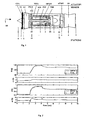
- FIG. 1 illustrates a schematic of a layout of an engine 10 as well as the station designations, sensors, and actuators for engine 10.
- Engine 10 is an aerodynamically coupled, dual rotor machine wherein a low-pressure rotor system (fan and low-pressure turbine) is mechanically independent of a high-pressure (core engine) system. Air entering the inlet is compressed by the fan and then split into two concentric streams. One of these then enters the high-pressure compressor and proceeds through the main engine combustor, high-pressure turbine, and low-pressure turbine. The other is directed through an annular duct and then recombined with the core flow, downstream of the low-pressure turbine, by means of a convoluted chute device. The combined streams then enter the augmenter to a convergent-divergent, variable area exhaust nozzle where the flow is pressurized, expands, and accelerated rearward into the atmosphere, thus generating thrust.
- a low-pressure rotor system fan and low-pressure turbine
- core engine high-pressure (core engine)
- the plant model is a physics based component level model (CLM) of this turbine configuration, which was developed by GE Aircraft Engines. This model is very detailed, high-fidelity, and models each component starting at the inlet, through the fan, compressor, combustor, turbines, and exhaust nozzle. Since NMPC is a model based control, an internal model is used to predict the future responses of the plant to control inputs. As the CLM is a very large and complicated model, a new model was developed to be used in the NMPC that has a small number of states, executes quickly, can be analytically linearized, and is accurate to within 20 percent transiently and 5 percent steady state over the area of the flight envelope that is most used.
- CLM physics based component level model
- the SRTM has two control inputs, fuel flow demand (WFDMD), and exhaust nozzle area demand (A8DMD), as well as ambient condition inputs; altitude (ALT), Mach (XM), and ambient temperature deviation from ISO (DTAMB).
- WFDMD fuel flow demand
- A8DMD exhaust nozzle area demand
- ambient condition inputs altitude (ALT), Mach (XM), and ambient temperature deviation from ISO (DTAMB).
- ALT altitude
- XM Mach
- DTAMB ambient temperature deviation from ISO
- the outputs are, percent core speed (PCN25), percent fan speed (PCN2), fan inlet pressure (P2), fan total exit pressure (P14), fan static exit pressure (PS14), compressor inlet pressure (P25), engine pressure ratio (PP), compressor discharge static pressure (PS3), compressor discharge total pressure (P3), fan airflow (W2R), compressor airflow (W25R), fan inlet temperature (T2), compressor inlet temperature (T25), high pressure turbine exit temperature (T4B), fan stall margin (SM2), core stall margin (SM25), and thrust (FNAV).
- a SRTM of an aircraft engine along with the main fuel metering valve (MFMV) and variable exhaust nozzle (A8) actuators is developed that meets the above specifications.
- the model is designed to replicate both transient and steady state performance.
- the inertias of both rotors are considered in the SRTM because they are the main factors affecting the engine transient performance.
- Other states include P3 which represents something similar to combustor volume, T42 which approximates the bulk flame dynamics, two states that represent fuel actuator dynamics, and 1 state that represents the A8 actuator dynamics.
- the model is data driven and is designed to use the steady state relationships/data from either a complex non-linear model, or from real engine data, and then fit parameters to transient data that account for the dynamics between the inputs and the other model states.
- the torques arise from any mismatches to the steady state relationships. For example, for a given PCN2 there is a steady state fuel flow.
- PCN2dot can be similarly acted upon by the other rotor PCN25.
- the same logic is used on the PCN25 rotor.
- the other engine dynamic elements of the SRTM including T42 and PS3 act in a similar way to the rotors.
- this part of the model there is a delay that is associated with computational delays, actuator delay, and transport delay of the fuel to the combustor.
- the actuator dynamics are modeled as 2nd order with rate and position limits.
- the A8 actuator is similar but is only 1st order actuator dynamics. Except for the FMV gain, all of the other parameters for this part of the model are found using nonlinear system identification.
- the other outputs from the model specified above are generated from table lookups based on the dynamic element outputs.
- the SRTM is run open loop versus the CLM.
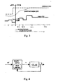
- the inputs profiles for the validation are a large step increase in fuel at 2 sec., small step decrease in fuel at 4 sec., small step increase in A8 at 6 sec., and a large step decrease in A8 at 8 sec.
- the results of one such comparison are shown in Figure 2 for PCN2 and PS3. While for this comparison both parameters are within 10 percent transiently and 5 percent steady state, for all of the parameters over all tested points in the defined envelope the maximal deviation transiently is 22 percent and the maximal deviation steady state is 7 percent.
- These adaptive model-based control systems may detect faults, failures and/or damage, and then take such information and incorporate it into the model(s), optimization(s), objective function(s), constraint(s) and/or parameter(s) in the control system, preferably in real-time. This information allows the control system to take optimized action given the current engine conditions. Since these control systems are updated and adapted in real-time, they allow for any level of deterioration, faults, failures or damage to be accommodated, not just faults, failures and damage that have a priori solutions already programmed into the model(s) in the control system.
- These adaptive model-based control systems and methods are designed to reduce operator workload and enable autonomous gas turbine operation by: (1) providing sufficient information to the supervisory control so that the supervisory control can manage propulsion, power and/or electrical output for the given mission or event; (2) elevating the level of autonomy in the engine control; (3) aiding the integration of the engine control with the supervisory control; and/or (4) improving engine-related decision-making capabilities.
- model-based control systems are created by designing a model of each component and/or system that is to be controlled. For example, there may be a model of each engine component and system - compressor, turbine, combustor, etc. Each model comprises features or dynamic characteristics about the component's or system's behavior over time (i.e., speed accelerations being the integral of the applied torques). From the model(s), the system may control, estimate, correct or identify output data based on the modeled information.
- the system can hold the control to that actuator fixed as an input constraint, and then adapt the controls that are output to the other actuators so that no other constraints are violated, and as much lost thrust power as possible can be regained so that the gas turbine may can continue operation.
- the models in the model-based controls are designed to replicate both transient and steady state performance.
- the models can be used in their non-linear form or they can be linearized or parameterized for different operating conditions.
- Model-based control techniques take advantage of the model to gain access to unmeasured engine parameters in addition to the normal sensed parameters. These unmeasured parameters may include thrust, stall margins, and airflows.
- These controls can be multiple-input multiple-output (MIMO) to account for interactions of the control loops, they are model-based to get rid of the scheduling, and they have limits or constraints built as an integral part of the control formulation and optimization to get rid of designing controllers for each limit.
- MIMO multiple-input multiple-output
- the current strategy for this invention involves trying to collapse the controller into an objective function(s) and constraint(s) that is used as part of a finite horizon constrained optimization problem.
- the objectives include attempting to maximize or minimize thrust, power, electricity, specific fuel consumption, part life, stress, temperatures, pressures, ratios of pressures, speed, actuator command(s), flow(s), dollars, costs, etc. This leads to longer engine run times, fuel savings, increased transient performance, increased parts life, and/or lower costs.
- the objectives include attempting to manage stall margin, increase operability, and prevent in-flight mishaps. This leads to reduction of loss of thrust or loss of power control events, increased engine operating time in presence of faults, failures, or damage and increased engine survivability.
- the herein described adaptive model-based control systems and methods that comprise a system model, estimators, model-based diagnostics, and model-based control or model-predictive control.
- Physics-based and empirical models provide analytical redundancy of sensed engine parameters and access to unmeasured parameters for control and diagnostics purposes as well as provide prediction of future behavior of the system.
- Estimators associated with the various models will ensure that the models are providing accurate representations of the engine and its subsystems and components as well as estimate the model state.
- Model-based diagnostics provide accurate engine condition information (deterioration, damage, and engine system failures), relying both on models and on sensed parameters.
- Nonlinear model predictive control maintains robust, high-performance control of the engine in the presence of system faults and mission segment-specific operational goals, using the predictive capabilities of model and information from the model-based diagnostics.
- Overall health management is the confluence of on-board diagnostics, fault-tolerant control, and an adaptation of the model-based controller.
- the control system needs to have as much information as possible about the engine or engine subsystem that it is controlling.
- One of the best methods to gain this information about the system is to use a dynamic model inside of the control. Doing this gives information about how different engine parameters should respond given the current ambient conditions and actuator commands, the relationships between parameters in the system, the relationships between measured and unmeasured parameters, and the parameters that indicate the health of the engine. If the model is dynamic, then all of this information is found on both a steady state and transient basis.
- the model can also be used to analyze a profile of past measurements or current performance, or it can be used to predict how the engine will behave over a future time horizon.
- the model can be linear or nonlinear, physics-based, or system identification based.
- the model can represent each of the main components of the engine at a system level, including the inlet, fan, compressor, combustor, high pressure turbine, low pressure turbine, afterburner, variable area exhaust nozzle, and other components or subsystems including actuators, fuel systems, and lube systems.
- One of the goals in designing this model will be to recreate the nominal engine or subsystem steady state and transient performance and use this model inside of the model-based control, and estimator.
- Another formulation would use models with faulted, failed, or damaged characteristics in a single or multi-model fault diagnostic system.
- the model should be able to track or adapt itself to follow these changes.
- One helpful idea is to get a model to reveal information about the particular engine running at the current time. This facilitates the ability to predict more accurately future behavior and to detect smaller faults or damage levels.
- Two areas of the model that can be modified to match the engine model to the current engine are engine parameters and states.
- the tool used to determine the engine parameters is called a parameter estimator, and the tool used to determine the states is a state estimator.
- a parameter estimator estimates and modifies parameters in the engine model in order to reduce the error between the engine sensors and the model sensors, or this is called tracking the model to the engine.
- the parameters that are modified usually fall in the class called quality parameters, e.g. component efficiencies, flow, input or output scalars or adders. These quality parameters like component efficiencies can then be used as inputs to the diagnostic algorithms. For example, if the compressor efficiency drops by a couple of points during steady state operation, it may indicate damage has occurred in the compressor. In this realization the parameter estimator works in real-time on both transient information and steady state information.
- a state estimator is used to also aid in tracking and is the state information is also used to initialize the model-based control at each time interval. Since the model-based control is a full state controller, it will use the estimate of the current state of the engine to initialize and function correctly.
- the goal of the state estimator is to determine the optimum gain K to account for the differences between the model and the engine, given the model dynamics and the covariance of w and v.
- the role of the diagnostics is to detect, isolate, and identify any fault, failure, or damage in the gas turbine system.
- the diagnostic system is based on model-based or multi-model based diagnostics where information from the other control components like the model and model structure, innovations, parameter updates, states, sensor values, sensor estimates are used to diagnose the engine upset. With this information the diagnostics determines if there is an upset, where the upset is located, and the magnitude of the upset and sends this information to the master mode selector and to the model-based controller.
- Model predictive control uses the model and the current state information in the control to predict the future behavior of the engine or system. Because a prediction of the future behavior can be formed given an evolution of control inputs, many different control moves can be tested over the future horizon to see which ones will track the desired references (e.g., speeds, pressure ratios, thrust) while still obeying any operating constraints (e.g., limits on the actuators, temperatures, speeds, pressures, torques). Then, once the control sequence that gives the desired results has been determined, the first control action in that sequence is implemented at the next sample period. The process is then repeated.
- desired references e.g., speeds, pressure ratios, thrust
- the power in this algorithm is that the controller can now see what the engine is going to do over the future time horizon, and at the same time it knows the engine operating constraints. The control can then modify all of the control actions to ensure that none of the constraints are violated while optimally satisfying the control objective. This means that the control will develop the best possible solution to meet the mission requirements.
- This best control sequence can be determined by converting the problem into a form that an optimization algorithm can solve.
- MPC is based on the constrained open-loop optimization of a finite horizon objective function. This optimization uses the dynamic system model to describe the evolution of the outputs and commences from an assumed known initial state.
- Figure 3 illustrates an implementation of NMPC based on the constrained open-loop optimization of a finite horizon objective function. This optimization uses a plant model to describe the evolution of the outputs and commences from an assumed known initial state.
- Figure 3 illustrates the concept of receding horizon control underpinning NMPC.
- the input variables, ⁇ u(k), u(k+1), ..., u(k+p-1) ⁇ are selected to optimize a performance criterion over the prediction horizon, p.
- the computed optimal control Only the values for the first sample, u(k), are actually implemented.
- the NMPC and the EKF state estimator are both model-based procedures in which a model of the plant is calculated for the generation of state predictions.
- the controlled inputs are fuel flow demand (WFDMD) and exhaust area demand (A8DMD). Since the control is model based it can be designed to follow the unmeasured but estimated or computed parameters of interest such as thrust and stall margin, but this studies first goal is to perform to the same requirements as the production control already running an engine.
- the references are fan speed (ref1) and engine pressure ratio (ref2). While operating to these two references, the control is constrained by other operating limitations, such as, for example, maximum T4B, minimum and maximum PS3, minimum and maximum N25, maximum N2, rotor speed acceleration, and rotor speed deceleration. Also, both actuators are rate limited and have minimum and maximum slew positions.
- the formulation of NMPC used to work within this framework is now detailed.
- the SRTM is used as the predictor to obtain the turbine cycle parameters' response over the prediction horizon.
- the constraints on cycle parameters like PS3 and T4B are included as soft constraints or penalty functions. This is implemented by using an exponential term that is very small, i.e. little effect on J, when operating away from the constraint, but penalizes J heavily when the parameter comes near the constraint.
- the ⁇ Wf and ⁇ A8 terms are added to both to make sure that the control does not attempt to take unfeasibly large steps, and also they are set to be just outside of the range of the actual input constraints to make sure that the gradient follows a direction that will correspond with the final solution.
- the control goal is min u J .
- u is the vector of p future WFCMD and A8CMD control inputs. This is accomplished using a gradient descent method with central differences.
- the gradient computation is shown in eq. (4).
- ⁇ J J ⁇ u + d u - J ⁇ u - d u 2
- d u ⁇ J ⁇ wfdm ⁇ d t ⁇ J ⁇ A ⁇ 8 ⁇ dm ⁇ d t ⁇ ⁇ ⁇ J ⁇ wfdm ⁇ d t + c ⁇ J ⁇ A ⁇ 8 ⁇ dm ⁇ d t + c 0 0 ⁇ ⁇ 0 t + p 0 t + p
- the control inputs are then computed by taking n steps in the negative gradient direction until J is minimized, or the maximum number of iterations or search time is reached.
- ⁇ is a weighting matrix that accounts for gradient step size and weighting between the two control inputs.
- NMPC is a full state feedback controller and hence all states need to be measured or estimated from available measurements. Typically not all states are measured because of the cost or availability of sensors. Moreover sensors have dynamics, delays, and noise. Hence a dynamic observer is useful to reconstruct the states and reduce noise.
- An Extended Kalman Filter (EKF) is used for this purpose. Useful EKF's are described in Athans, M. (1996), The Control Handbook, pg. 589-594, CRC Press, United States , and B.D.O. Anderson and J.B. Moore, Optimal Filtering, Prentice-Hall, Englewood Cliffs NJ, 1979 .
- the EKF is a nonlinear state estimator which is based on a dynamical system model. While the model underpinning the EKF is nonlinear, the recursion is based on a linear gain computed from the parameters of the linearized model. Thus the design concepts inherit much from the realm of Kalman Filtering.
- the SRTM is used as the core of the EKF, which is a parallel with its use in the NMPC.
- the EKF need not provide the truly optimal state estimate to the controller in order to operate adequately well. It is usually a suboptimal nonlinear filter in any case. However, its role in providing the state estimates to the NMPC for correct initialisation is a key feature of NMPC which is often overlooked.
- FIG. 4 illustrates a block diagram representation of how EKF, SRTM, NMPC, and CLM are connected.
- the assembled control process starts with the EKF using the SRTM to determine the current state of the engine. This information is used as the initial conditions for the predictions used in the gradient calculation.
- the SRTM is then run 2*c times where 2 is the number of control inputs and c the control horizon used is 15 steps. The sample time is 10 mseconds for each time step. Each run corresponds to a perturbation at a different point in the control horizon. This information is assembled into the gradient and a search path is followed in the negative gradient direction.
- This simulation configuration with the NMPC control algorithm is run for a step demand in power from the pilot. This is a critical simulation that would be used to replicate an aircraft takeoff, combat, or ground avoidance maneuver.
- the PCN2 reference (ref1) is stepped up to increase the resulting thrust.
- PP reference (ref2) is reduced to maintain sufficient fan stall margin.
- Both PCN2 and PP try to follow the references for the first 4 seconds with PCN2 reaching the reference and PP resulting in a steady state error.
- the response time of PCN2 to the reference is limited mainly by the changing maximum constraint on WFDMD. This maximum constraint is used in the production control as an acceleration limiter to protect against compressor surge or stall.
- the PP steady state error is due to the A8CMD hitting the minimum constraint and PCN2 being weighted more heavily in the objective function.
- the results of the production control to the same step input are within 4 percent transiently and 0.2% steady state.
- NMPC can recreate the current production control, using this technology may unlock many potential benefits.
- Using the model based properties of NMPC can lead to running to other more attractive references like thrust and stall margin.
- the model can also be used for fault detection, isolation, and accommodation.
- the open architecture of NMPC allows for many extensions and variations that may allow for performance, operability, or survivability improvements.
Landscapes
- Engineering & Computer Science (AREA)
- Chemical & Material Sciences (AREA)
- Combustion & Propulsion (AREA)
- Artificial Intelligence (AREA)
- General Engineering & Computer Science (AREA)
- Health & Medical Sciences (AREA)
- Mechanical Engineering (AREA)
- Computer Vision & Pattern Recognition (AREA)
- Evolutionary Computation (AREA)
- Medical Informatics (AREA)
- Software Systems (AREA)
- Physics & Mathematics (AREA)
- General Physics & Mathematics (AREA)
- Automation & Control Theory (AREA)
- Feedback Control In General (AREA)
Claims (5)
- System zur Auslegung des Betriebs und der Regelung eines Flugzeug-Gasturbinentriebwerks (10), wobei das System aufweist:eine Berechnungseinheit mit einer Eingabeeinheit zum Erzeugen eines Betriebsmodells für das Flugzeug-Gasturbinentriebwerk, so dass es wenigstens eine Zielfunktion (J) enthält, und zum Definieren von Betriebs- und Regelungseinschränkungen für das Betriebsmodell des Flugzeug-Gasturbinentriebwerks; undeine dynamische Online-Optimierungs/Regelungs-Einrichtung, die dafür konfiguriert ist, den Betrieb des Gasturbinentriebwerks dynamisch unter Anwendung einer modellprädiktiven Regelung auf der Basis des Betriebsmodells und der Betriebs- und Regelungseinschränkungen unter Verwendung eines erweiterten Kalman-Filters zur Abschätzung zu optimieren und zu regeln, dadurch gekennzeichnet, dassdie Optimierungs/Regelungs-Einrichtung dafür konfiguriert ist, den Gradienten von J zu berechnen, wobei

- System nach Anspruch 1, wobei die Optimierungs/Regelungs-Einrichtung dafür konfiguriert ist, die nachstehenden Schritte in einer Schleife durchzuführen: (A) Abschätzen des Ist-Zustands des Triebwerks (10) und zutreffender Einschränkungen; (B) für eine vorgegebene Regelungs/Simulations-Zeitperiode Ermitteln einer Regelungsaktion durch Optimierung einer Zielfunktion auf der Basis des Betriebsmodells unter Berücksichtigung der zutreffenden Einschränkungen; (C) Ausführen der im Schritt (B) ermittelten Regelungsaktion.
- System nach Anspruch 1, wobei die Optimierungs/Regelungs-Einrichtung dafür konfiguriert ist, den Gradienten in einer negativen Richtung zu verstellen, bis eine Anzahl von Schritten gleich einer vorbestimmten Anzahl ist.
- System nach Anspruch 1, wobei die Optimierungs/Regelungs-Einrichtung dafür konfiguriert ist, den Gradienten in einer negativen Richtung zu verstellen, bis J minimiert ist.
- System nach Anspruch 1, wobei die Optimierungs/Regelungs-Einrichtung dafür konfiguriert ist, den Gradienten in einer negativen Richtung zu verstellen, bis eine verstrichene Zeit ein vorbestimmtes Zeitintervall überschreitet.
Priority Applications (2)
| Application Number | Priority Date | Filing Date | Title |
|---|---|---|---|
| EP03257655A EP1538319B1 (de) | 2003-12-05 | 2003-12-05 | Vorrichtung zur modell-prädikativen Regelung eines Flugzeugtriebwerkes |
| DE60327440T DE60327440D1 (de) | 2003-12-05 | 2003-12-05 | Vorrichtung zur modell-prädikativen Regelung eines Flugzeugtriebwerkes |
Applications Claiming Priority (1)
| Application Number | Priority Date | Filing Date | Title |
|---|---|---|---|
| EP03257655A EP1538319B1 (de) | 2003-12-05 | 2003-12-05 | Vorrichtung zur modell-prädikativen Regelung eines Flugzeugtriebwerkes |
Publications (2)
| Publication Number | Publication Date |
|---|---|
| EP1538319A1 EP1538319A1 (de) | 2005-06-08 |
| EP1538319B1 true EP1538319B1 (de) | 2009-04-29 |
Family
ID=34443082
Family Applications (1)
| Application Number | Title | Priority Date | Filing Date |
|---|---|---|---|
| EP03257655A Expired - Lifetime EP1538319B1 (de) | 2003-12-05 | 2003-12-05 | Vorrichtung zur modell-prädikativen Regelung eines Flugzeugtriebwerkes |
Country Status (2)
| Country | Link |
|---|---|
| EP (1) | EP1538319B1 (de) |
| DE (1) | DE60327440D1 (de) |
Cited By (1)
| Publication number | Priority date | Publication date | Assignee | Title |
|---|---|---|---|---|
| CN108549228A (zh) * | 2018-04-18 | 2018-09-18 | 南京工业大学 | 一种基于交叉评估的多变量dmc系统模型失配通道定位方法 |
Families Citing this family (16)
| Publication number | Priority date | Publication date | Assignee | Title |
|---|---|---|---|---|
| US7363094B2 (en) | 2006-01-09 | 2008-04-22 | General Electric Company | Multivariable controller design method for multiple input/outputs systems with multiple input/output constraints |
| EP1950636B1 (de) * | 2007-01-23 | 2010-05-26 | General Electric Company | Multivariables Steuerungsdesignverfahren für mehrere Eingabe-/Ausgabe-Systeme mit mehreren Eingabe-/Ausgabe-Beschränkungen |
| GB201012442D0 (en) * | 2010-07-26 | 2010-09-08 | Rolls Royce Plc | System control |
| US20120083933A1 (en) * | 2010-09-30 | 2012-04-05 | General Electric Company | Method and system to predict power plant performance |
| US8490404B1 (en) * | 2012-02-28 | 2013-07-23 | General Electric Company | Sensor-based performance-seeking gas turbine engine control |
| US9494086B2 (en) | 2014-02-28 | 2016-11-15 | General Electric Company | Systems and methods for improved combined cycle control |
| US9441547B2 (en) | 2014-06-02 | 2016-09-13 | United Technologies Corporation | Model-based optimal control for stall margin limit protection in an aircraft engine |
| CN110219736B (zh) * | 2019-06-19 | 2020-02-18 | 南京航空航天大学 | 基于非线性模型预测控制的航空发动机直接推力控制方法 |
| CN111456856B (zh) * | 2020-04-04 | 2023-03-24 | 西北工业大学 | 航空发动机最大推力状态降保守性鲁棒控制器 |
| CN111694277B (zh) * | 2020-06-12 | 2021-09-10 | 华北电力大学 | 一种基于多步状态反馈的非线性随机模型预测控制方法 |
| CN112377311A (zh) * | 2020-06-15 | 2021-02-19 | 西北工业大学 | 输入受限的航空发动机鲁棒增益调度容错控制器 |
| CN112327669B (zh) * | 2020-11-14 | 2022-02-18 | 大连理工大学 | 一种航空发动机显式预测控制器的设计方法 |
| CN117170225B (zh) * | 2023-10-09 | 2024-04-09 | 清华大学 | 基于转子加速度反馈的航空发动机增量式控制器 |
| WO2025202046A1 (en) * | 2024-03-25 | 2025-10-02 | Nuovo Pignone Tecnologie - S.R.L. | Nonlinear model predictive anti-surge control of a centrifugal compressor |
| CN117970895B (zh) * | 2024-03-29 | 2024-07-02 | 国网浙江省电力有限公司营销服务中心 | 一种基于㶲分析的钢铁生产过程能效诊断及优化方法和系统 |
| CN119511701B (zh) * | 2024-10-28 | 2025-09-05 | 西安交通大学 | 发动机输入协同自调整模型建模方法、系统、介质及设备 |
Family Cites Families (2)
| Publication number | Priority date | Publication date | Assignee | Title |
|---|---|---|---|---|
| US4215412A (en) * | 1978-07-13 | 1980-07-29 | The Boeing Company | Real time performance monitoring of gas turbine engines |
| GB2211965B (en) * | 1987-10-31 | 1992-05-06 | Rolls Royce Plc | Data processing systems |
-
2003
- 2003-12-05 EP EP03257655A patent/EP1538319B1/de not_active Expired - Lifetime
- 2003-12-05 DE DE60327440T patent/DE60327440D1/de not_active Expired - Lifetime
Non-Patent Citations (1)
| Title |
|---|
| JOE QIN S.; THOMAS A. BADGWELL: "A survey of industrial model predictive control technology", CONTROL ENGINEERING PRACTICE, vol. 11, no. 7, July 2003 (2003-07-01), pages 733 - 764, XP002435295 * |
Cited By (2)
| Publication number | Priority date | Publication date | Assignee | Title |
|---|---|---|---|---|
| CN108549228A (zh) * | 2018-04-18 | 2018-09-18 | 南京工业大学 | 一种基于交叉评估的多变量dmc系统模型失配通道定位方法 |
| CN108549228B (zh) * | 2018-04-18 | 2021-02-02 | 南京工业大学 | 一种基于交叉评估的多变量dmc系统模型失配通道定位方法 |
Also Published As
| Publication number | Publication date |
|---|---|
| EP1538319A1 (de) | 2005-06-08 |
| DE60327440D1 (de) | 2009-06-10 |
Similar Documents
| Publication | Publication Date | Title |
|---|---|---|
| US6823253B2 (en) | Methods and apparatus for model predictive control of aircraft gas turbine engines | |
| EP1571509A1 (de) | Modelbasierte Steurungssysteme und Verfahren für Gasturbinentriebwerke | |
| EP1538319B1 (de) | Vorrichtung zur modell-prädikativen Regelung eines Flugzeugtriebwerkes | |
| US6823675B2 (en) | Adaptive model-based control systems and methods for controlling a gas turbine | |
| US7904282B2 (en) | Method and system for fault accommodation of machines | |
| Kobayashi et al. | Application of a constant gain extended Kalman filter for in-flight estimation of aircraft engine performance parameters | |
| JP4555562B2 (ja) | 航空機用ガスタービンのモデル予測制御のための方法及び装置 | |
| EP2149824B1 (de) | Verfahren und Systeme zur Schätzung der Betriebsparameter eines Motors | |
| US8315741B2 (en) | High fidelity integrated heat transfer and clearance in component-level dynamic turbine system control | |
| US20080234994A1 (en) | Method and system for accommodating deterioration characteristics of machines | |
| Brunell et al. | Nonlinear model predictive control of an aircraft gas turbine engine | |
| Connolly et al. | Advanced control considerations for turbofan engine design | |
| Adibhatla et al. | Model-based intelligent digital engine control (MoBIDEC) | |
| Saluru et al. | Fault tolerant model predictive control of a turbofan engine using C-MAPSS40k | |
| Zhu et al. | Self-evolution direct thrust control for turbofan engine individuals based on reinforcement learning methods | |
| Brunell et al. | Model adaptation and nonlinear model predictive control of an aircraft engine | |
| Connolly et al. | Propulsion controls modeling for a small turbofan engine | |
| Peng et al. | Multivariable decoupling control of civil turbofan engines based on fully actuated system approach | |
| Sanusi et al. | Reinforcement learning for condition-based control of gas turbine engines | |
| Saluru et al. | Active fault tolerant model predictive control of a turbofan engine using C-MAPSS40k | |
| Viassolo et al. | Advanced estimation for aircraft engines | |
| Turevskiy et al. | A model-based controller for commercial aero gas turbines | |
| DeHoff et al. | Optimal control of turbine engines | |
| Behbahani et al. | Integrated model-based controls and PHM for improving turbine engine performance, reliability, and cost | |
| Lin et al. | Multivariable control of the j-85 turbojet engine for full flight envelope operation |
Legal Events
| Date | Code | Title | Description |
|---|---|---|---|
| PUAI | Public reference made under article 153(3) epc to a published international application that has entered the european phase |
Free format text: ORIGINAL CODE: 0009012 |
|
| AK | Designated contracting states |
Kind code of ref document: A1 Designated state(s): AT BE BG CH CY CZ DE DK EE ES FI FR GB GR HU IE IT LI LU MC NL PT RO SE SI SK TR |
|
| AX | Request for extension of the european patent |
Extension state: AL LT LV MK |
|
| 17P | Request for examination filed |
Effective date: 20051208 |
|
| AKX | Designation fees paid |
Designated state(s): CH DE FR GB LI SE |
|
| GRAP | Despatch of communication of intention to grant a patent |
Free format text: ORIGINAL CODE: EPIDOSNIGR1 |
|
| GRAS | Grant fee paid |
Free format text: ORIGINAL CODE: EPIDOSNIGR3 |
|
| GRAA | (expected) grant |
Free format text: ORIGINAL CODE: 0009210 |
|
| AK | Designated contracting states |
Kind code of ref document: B1 Designated state(s): CH DE FR GB LI SE |
|
| REG | Reference to a national code |
Ref country code: GB Ref legal event code: FG4D |
|
| REG | Reference to a national code |
Ref country code: CH Ref legal event code: EP |
|
| REG | Reference to a national code |
Ref country code: CH Ref legal event code: NV Representative=s name: SERVOPATENT GMBH |
|
| REF | Corresponds to: |
Ref document number: 60327440 Country of ref document: DE Date of ref document: 20090610 Kind code of ref document: P |
|
| REG | Reference to a national code |
Ref country code: SE Ref legal event code: TRGR |
|
| PLBE | No opposition filed within time limit |
Free format text: ORIGINAL CODE: 0009261 |
|
| STAA | Information on the status of an ep patent application or granted ep patent |
Free format text: STATUS: NO OPPOSITION FILED WITHIN TIME LIMIT |
|
| 26N | No opposition filed |
Effective date: 20100201 |
|
| REG | Reference to a national code |
Ref country code: FR Ref legal event code: PLFP Year of fee payment: 13 |
|
| REG | Reference to a national code |
Ref country code: FR Ref legal event code: PLFP Year of fee payment: 14 |
|
| PGFP | Annual fee paid to national office [announced via postgrant information from national office to epo] |
Ref country code: GB Payment date: 20161228 Year of fee payment: 14 Ref country code: CH Payment date: 20161227 Year of fee payment: 14 |
|
| PGFP | Annual fee paid to national office [announced via postgrant information from national office to epo] |
Ref country code: FR Payment date: 20161227 Year of fee payment: 14 Ref country code: SE Payment date: 20161129 Year of fee payment: 14 |
|
| PGFP | Annual fee paid to national office [announced via postgrant information from national office to epo] |
Ref country code: DE Payment date: 20161229 Year of fee payment: 14 |
|
| REG | Reference to a national code |
Ref country code: DE Ref legal event code: R119 Ref document number: 60327440 Country of ref document: DE |
|
| REG | Reference to a national code |
Ref country code: CH Ref legal event code: PL |
|
| GBPC | Gb: european patent ceased through non-payment of renewal fee |
Effective date: 20171205 |
|
| PG25 | Lapsed in a contracting state [announced via postgrant information from national office to epo] |
Ref country code: SE Free format text: LAPSE BECAUSE OF NON-PAYMENT OF DUE FEES Effective date: 20171206 |
|
| REG | Reference to a national code |
Ref country code: FR Ref legal event code: ST Effective date: 20180831 |
|
| PG25 | Lapsed in a contracting state [announced via postgrant information from national office to epo] |
Ref country code: DE Free format text: LAPSE BECAUSE OF NON-PAYMENT OF DUE FEES Effective date: 20180703 Ref country code: FR Free format text: LAPSE BECAUSE OF NON-PAYMENT OF DUE FEES Effective date: 20180102 |
|
| PG25 | Lapsed in a contracting state [announced via postgrant information from national office to epo] |
Ref country code: LI Free format text: LAPSE BECAUSE OF NON-PAYMENT OF DUE FEES Effective date: 20171231 Ref country code: CH Free format text: LAPSE BECAUSE OF NON-PAYMENT OF DUE FEES Effective date: 20171231 Ref country code: GB Free format text: LAPSE BECAUSE OF NON-PAYMENT OF DUE FEES Effective date: 20171205 |