EP1538252A1 - Plastic tub for a clothes washing machine - Google Patents
Plastic tub for a clothes washing machine Download PDFInfo
- Publication number
- EP1538252A1 EP1538252A1 EP03027556A EP03027556A EP1538252A1 EP 1538252 A1 EP1538252 A1 EP 1538252A1 EP 03027556 A EP03027556 A EP 03027556A EP 03027556 A EP03027556 A EP 03027556A EP 1538252 A1 EP1538252 A1 EP 1538252A1
- Authority
- EP
- European Patent Office
- Prior art keywords
- hub
- tub
- shell
- circular
- washing machine
- Prior art date
- Legal status (The legal status is an assumption and is not a legal conclusion. Google has not performed a legal analysis and makes no representation as to the accuracy of the status listed.)
- Withdrawn
Links
Images


Classifications
-
- D—TEXTILES; PAPER
- D06—TREATMENT OF TEXTILES OR THE LIKE; LAUNDERING; FLEXIBLE MATERIALS NOT OTHERWISE PROVIDED FOR
- D06F—LAUNDERING, DRYING, IRONING, PRESSING OR FOLDING TEXTILE ARTICLES
- D06F37/00—Details specific to washing machines covered by groups D06F21/00 - D06F25/00
- D06F37/26—Casings; Tubs
- D06F37/261—Tubs made by a specially selected manufacturing process or characterised by their assembly from elements
- D06F37/262—Tubs made by a specially selected manufacturing process or characterised by their assembly from elements made of plastic material, e.g. by injection moulding
-
- D—TEXTILES; PAPER
- D06—TREATMENT OF TEXTILES OR THE LIKE; LAUNDERING; FLEXIBLE MATERIALS NOT OTHERWISE PROVIDED FOR
- D06F—LAUNDERING, DRYING, IRONING, PRESSING OR FOLDING TEXTILE ARTICLES
- D06F37/00—Details specific to washing machines covered by groups D06F21/00 - D06F25/00
- D06F37/26—Casings; Tubs
- D06F37/261—Tubs made by a specially selected manufacturing process or characterised by their assembly from elements
- D06F37/263—Tubs made by a specially selected manufacturing process or characterised by their assembly from elements assembled from at least two elements connected to each other; Connecting or sealing means therefor
-
- D—TEXTILES; PAPER
- D06—TREATMENT OF TEXTILES OR THE LIKE; LAUNDERING; FLEXIBLE MATERIALS NOT OTHERWISE PROVIDED FOR
- D06F—LAUNDERING, DRYING, IRONING, PRESSING OR FOLDING TEXTILE ARTICLES
- D06F37/00—Details specific to washing machines covered by groups D06F21/00 - D06F25/00
- D06F37/26—Casings; Tubs
- D06F37/264—Tubs provided with reinforcing structures, e.g. ribs, inserts, braces
-
- D—TEXTILES; PAPER
- D06—TREATMENT OF TEXTILES OR THE LIKE; LAUNDERING; FLEXIBLE MATERIALS NOT OTHERWISE PROVIDED FOR
- D06F—LAUNDERING, DRYING, IRONING, PRESSING OR FOLDING TEXTILE ARTICLES
- D06F37/00—Details specific to washing machines covered by groups D06F21/00 - D06F25/00
- D06F37/26—Casings; Tubs
- D06F37/267—Tubs specially adapted for mounting thereto components or devices not provided for in preceding subgroups
- D06F37/269—Tubs specially adapted for mounting thereto components or devices not provided for in preceding subgroups for the bearing of the rotary receptacle
Definitions
- the present invention relates to a new tub for a clothes washing machine, in particular a washing machine of front-loading type, said tub being made of plastic material and provided with an improved rear wall.
- Plastic washing tubs for clothes washing machines are well known and substantially comprise a rigid structure forming a peripheral cylindrical envelope and a rear circular wall.
- reinforcing ribs are integrally provided so as to increase the strength of the structure.
- said ribs are arranged both circularly and radially in respect to the central portion of the rear wall.
- a passing through hub is provided at the centre of the rear wall for supporting the bearing of a central shaft by means of which a clothes containing drum is driven into rotation within the tub.
- Plastic washing tubs of this type are disclosed, for instance, in GB 2 261 881, EP 0 736 117 and EP 0 835 729.
- a washing tub is produced in a two-pieces construction, i.e. a front shell and a rear shell, by injection moulding of plastic material.
- the two shells are joined together by using any known means.
- the hub is provided in the centre of the rear shell.
- the hub in the rear shell is made in cast iron and is embedded in the over injected plastic material.
- Another purpose of the present invention is to maintain the tub structure of a clothes washing machine of current type, but with a reduced and constant thickness of the rear part of the tub, so as the injection moulding cycle for producing it is correspondingly reduced.
- a tub for washing machine is schematically shown in Figure 1, wherein a front tub shell 10 and a rear tub shell 11 are represented in a perspective exploded view.
- the front shell 10 and the rear shell 11 are generally made by injection moulding of plastic material and are assembled by any known means, e.g. screws.
- the rear shell 11 is substantially formed by a rigid body having a peripheral cylindrical envelope 12 and a rear circular wall 13.
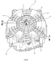
- the rear shell 11 is represented as a perspective view in Figure 2, this view being taken from the rear bottom of the tub.
- the rear circular wall 13 shows a profile which is made of alternate sectors 14, 15, inwardly and outwardly directed, respectively, with respect to the axis of symmetry of the tub. Said sectors are developed along a circular crown, which starts from the external edge of the shell and extends to about half of the radius of the shell.
- the shell in Figure 2 presents six sectors 14 and six sectors 15, but it is easy to understand that a different number of them may be carried out depending on the requested design of the tub.
- each of the sectors 14, 15 is shaped with ribs 16 which run both in radial and circular direction, mutually crossing, so as the strength of the rear shell is increased.
- the rear circular wall 13 of the shell 11 is provided with a special profile in correspondence of its internal annular portion 17 which surrounds a central hub 18 for the spindle for the drum (not represented), as disclosed here below.
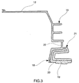
- FIG 3 shows a schematic section of the rear shell 11, taken along line A-A of Figure 2, wherein the cylindrical envelope 12 and the central hub 18 are represented.
- the hub 18 is normally made with a core 19 of cast iron and is over injected by plastic material 20.
- the plastic coating 20 has a constant thickness, as shown, but it ensures a stiffness comparable to that of the previous known solution, which had a bigger plastic coating. This is due thanks to the additional crown of radial ribs 21 that is provided between the hub 18 and the envelope 12. There is also to note that the radial ribs 21 are connected together with the cylindrical envelope 12 through the ribbed sectors 15 of the rear wall 13. Moreover, between the rib 21 and ribs 15 is interposed a flat ring 22 which is substantially parallel to the rear wall 13, i.e. orthogonal to the rotation axis of the rear shell 12, see Figures 3 and 4.
- the bottom surface 22 of said circular crown of radial ribs 21 is in a plane different from those of the circular sectors 14,15. More precisely, the bottom surface 22 of said circular crown of radial ribs 21 is in a plane which is intermediate between the planes of adjacent circular sectors 14,15.
- the thickness of the plastic material over injected on the hub (18) may be steady all around the hub and substantially even to that of the ribs (14,15,21) on the rear wall (13) of the rear shell (11).
- the whole shell 12 is integrally moulded and its specific profile is also designed with planes and undercuts, so as its is extraction from the mould may be particularly easy and advantageous.
Landscapes
- Engineering & Computer Science (AREA)
- Textile Engineering (AREA)
- Main Body Construction Of Washing Machines And Laundry Dryers (AREA)
Abstract
A plastic tub for a clothes washing machine, in particular a washing machine of
front-loading type, comprising a front shell (10) and a rear shell (11), the rear shell
being formed by a cylindrical envelope (12) and a rear wall (13) provided with
reinforcing ribs, a passing through hub (18) provided at the centre of the rear wall
for supporting the bearing of a central shaft by means of which a clothes containing
drum is driven into rotation within the tub, said hub (18) being made by cast iron
over injected by plastic material.
The rear circular wall (13) of the rear shell (11) is shaped with a plurality of ribbed
circular sectors (14,15) alternatively oriented in opposite axial direction, and at
least one circular crown of radial ribs (21) is provided around the hub.
The tub structure results with a reduced and constant thickness of the rear part of
the tub, so as the injection moulding cycle for producing it is correspondingly
reduced.
Description
- The present invention relates to a new tub for a clothes washing machine, in particular a washing machine of front-loading type, said tub being made of plastic material and provided with an improved rear wall.
- Plastic washing tubs for clothes washing machines are well known and substantially comprise a rigid structure forming a peripheral cylindrical envelope and a rear circular wall.
- Usually, in correspondence of the rear wall of the tub, reinforcing ribs are integrally provided so as to increase the strength of the structure. In a preferred way, said ribs are arranged both circularly and radially in respect to the central portion of the rear wall.
- A passing through hub is provided at the centre of the rear wall for supporting the bearing of a central shaft by means of which a clothes containing drum is driven into rotation within the tub.
- Plastic washing tubs of this type are disclosed, for instance, in GB 2 261 881, EP 0 736 117 and EP 0 835 729.
- At present, a washing tub is produced in a two-pieces construction, i.e. a front shell and a rear shell, by injection moulding of plastic material. The two shells are joined together by using any known means. Of course, the hub is provided in the centre of the rear shell.
- Such a solution ensures both the support of the drum shaft and a watertight sealing of the tub, but has the drawback that the hub itself is directly exposed to the relatively high temperatures to which the washing liquor is usually heated up, said washing liquor touching directly the central portion of the rear shell.
- This fact, owing to the mechanical action exerted by the rotating shaft against said hub, leads to a gradual stressing of the plastic material which, after a certain period, undergoes an aging process with a decay in its overall mechanical properties.
- Therefore, in order to overcome this drawback the hub in the rear shell is made in cast iron and is embedded in the over injected plastic material.
- This known solution, however, provides a large and not uniform thickness for the section of the rear shell, due to the mechanical constraints in the ejection from the mould. As a consequence, the tub moulding requires a long cycle time which reduces the moulding productivity and results in a costly working process.
- It is therefore a purpose of the present invention to provide a plastic tub for a clothes washing machine having improved structural and functional characteristics with respect to prior art tubs, which is capable of ensuring long-term resistance to risks of decay and resulting loosening of the hub.
- Another purpose of the present invention is to maintain the tub structure of a clothes washing machine of current type, but with a reduced and constant thickness of the rear part of the tub, so as the injection moulding cycle for producing it is correspondingly reduced.
- According the present invention, this purpose is achieved by a washing tub as described in the appended claims.
- The invention will be better appreciated from the following description given solely by way of non-limiting example and with reference to the accompanying drawings in which:
- Figure 1 shows schematically a perspective exploded view of a tub for washing machine according to the present invention;
- Figure 2 shows a perspective view of the rear shell of the tub represented in Figure 1;
- Figure 3 shows a partial section of the rear shell of the tub of Figure 2, taken along line A-A; and
- Figure 4 shows a partial section of the rear shell of the tub of Figure 2, taken along line B-B.
- A tub for washing machine according with the present invention is schematically shown in Figure 1, wherein a
front tub shell 10 and arear tub shell 11 are represented in a perspective exploded view. Thefront shell 10 and therear shell 11 are generally made by injection moulding of plastic material and are assembled by any known means, e.g. screws. - The
rear shell 11 is substantially formed by a rigid body having a peripheralcylindrical envelope 12 and a rearcircular wall 13. - The
rear shell 11 is represented as a perspective view in Figure 2, this view being taken from the rear bottom of the tub. - According with a feature of the invention, the rear
circular wall 13 shows a profile which is made ofalternate sectors - The shell in Figure 2 presents six
sectors 14 and sixsectors 15, but it is easy to understand that a different number of them may be carried out depending on the requested design of the tub. - Each of the
sectors ribs 16 which run both in radial and circular direction, mutually crossing, so as the strength of the rear shell is increased. According with a main feature of the invention, the rearcircular wall 13 of theshell 11 is provided with a special profile in correspondence of its internalannular portion 17 which surrounds acentral hub 18 for the spindle for the drum (not represented), as disclosed here below. - Figure 3 shows a schematic section of the
rear shell 11, taken along line A-A of Figure 2, wherein thecylindrical envelope 12 and thecentral hub 18 are represented. Thehub 18 is normally made with acore 19 of cast iron and is over injected byplastic material 20. - The
plastic coating 20 has a constant thickness, as shown, but it ensures a stiffness comparable to that of the previous known solution, which had a bigger plastic coating. This is due thanks to the additional crown ofradial ribs 21 that is provided between thehub 18 and theenvelope 12. There is also to note that theradial ribs 21 are connected together with thecylindrical envelope 12 through the ribbedsectors 15 of therear wall 13. Moreover, between therib 21 andribs 15 is interposed aflat ring 22 which is substantially parallel to therear wall 13, i.e. orthogonal to the rotation axis of therear shell 12, see Figures 3 and 4. - Therefore, the
bottom surface 22 of said circular crown ofradial ribs 21 is in a plane different from those of thecircular sectors bottom surface 22 of said circular crown ofradial ribs 21 is in a plane which is intermediate between the planes of adjacentcircular sectors - Thanks to the disclosed technical solution, the thickness of the plastic material over injected on the hub (18) may be steady all around the hub and substantially even to that of the ribs (14,15,21) on the rear wall (13) of the rear shell (11).
- Of course, the
whole shell 12 is integrally moulded and its specific profile is also designed with planes and undercuts, so as its is extraction from the mould may be particularly easy and advantageous.
Claims (4)
- A plastic tub for a clothes washing machine, in particular a washing machine of front-loading type, comprising a front shell (10) and a rear shell (11), the rear shell being formed by a cylindrical envelope (12) and a rear wall (13) provided with reinforcing ribs, a passing through hub (18) provided at the centre of the rear wall for supporting the bearing of a central shaft by means of which a clothes containing drum is driven into rotation within the tub, said hub (18) being made by cast iron over injected by plastic material, characterised in that the rear circular wall (13) of the rear shell (11) is shaped with a plurality of ribbed circular sectors (14,15) alternatively oriented in opposite axial direction, and at least one circular crown of radial ribs (2 1 ) is provided around the hub.
- A plastic tub according to claim 1, characterised in that the bottom surface (22) of said circular crown of radial ribs (21) is in a plane different from those of the circular sectors (14,15).
- A plastic tub according to claim 1, characterised in that the bottom surface (22) of said circular crown of radial ribs (21) is in a plane which is intermediate between the planes of adjacent circular sectors (14,15).
- A plastic tub according to claim 1 to 3, characterised in that the thickness of the plastic material over injected on the hub (18) is steady all around the hub and substantially even to that of the ribs (14,15,21) on the rear wall (13) of the rear shell (11).
Priority Applications (1)
| Application Number | Priority Date | Filing Date | Title |
|---|---|---|---|
| EP03027556A EP1538252A1 (en) | 2003-12-01 | 2003-12-01 | Plastic tub for a clothes washing machine |
Applications Claiming Priority (1)
| Application Number | Priority Date | Filing Date | Title |
|---|---|---|---|
| EP03027556A EP1538252A1 (en) | 2003-12-01 | 2003-12-01 | Plastic tub for a clothes washing machine |
Publications (1)
| Publication Number | Publication Date |
|---|---|
| EP1538252A1 true EP1538252A1 (en) | 2005-06-08 |
Family
ID=34442919
Family Applications (1)
| Application Number | Title | Priority Date | Filing Date |
|---|---|---|---|
| EP03027556A Withdrawn EP1538252A1 (en) | 2003-12-01 | 2003-12-01 | Plastic tub for a clothes washing machine |
Country Status (1)
| Country | Link |
|---|---|
| EP (1) | EP1538252A1 (en) |
Cited By (16)
| Publication number | Priority date | Publication date | Assignee | Title |
|---|---|---|---|---|
| EP1717364A1 (en) * | 2005-04-25 | 2006-11-02 | Miele & Cie. KG | Plastic tub for a washing machine |
| EP1788137A1 (en) * | 2005-11-16 | 2007-05-23 | Miele & Cie. KG | Plastic tub for a laundry treatment machine and laundry treatment machine |
| EP1813707A1 (en) * | 2006-01-27 | 2007-08-01 | LG Electronics Inc. | Tub for washing machine and method of manufacturing the same |
| WO2007113228A1 (en) | 2006-03-31 | 2007-10-11 | Arcelik Anonim Sirketi | A noise-reduced tub for a washer/dryer |
| US7398663B2 (en) * | 2002-10-16 | 2008-07-15 | Lg Electronics Inc. | Drum-type washing machine |
| WO2008125974A3 (en) * | 2007-04-17 | 2009-03-05 | Indesit Co Spa | Laundry washing machine |
| WO2008000873A3 (en) * | 2006-06-22 | 2010-11-25 | Fundación Aitiip | Lightweight washtub structure for washing machine |
| EP2270273A1 (en) | 2009-06-29 | 2011-01-05 | Electrolux Home Products Corporation N.V. | Washing machine |
| WO2011072712A1 (en) * | 2009-12-14 | 2011-06-23 | BSH Bosch und Siemens Hausgeräte GmbH | Plastic component, in particular plastic suds container, and method for producing the plastic component |
| CN101796240B (en) * | 2007-09-07 | 2011-12-14 | Bsh博施及西门子家用器具有限公司 | Plastic washing machine barrel |
| RU2454492C2 (en) * | 2007-02-21 | 2012-06-27 | Мекканика Дженерале С.Р.Л. | Washing machine tank equipped with external reinforcing cover on lower wall |
| DE112006003872B4 (en) * | 2006-04-28 | 2013-05-16 | Lg Electronics Inc. | Tub for a washing machine |
| EP2671997A1 (en) * | 2012-06-04 | 2013-12-11 | Electrolux Home Products Corporation N.V. | Laundry machine comprising a laundry treatment unit with direct drive arrangement |
| US10487435B2 (en) | 2017-03-23 | 2019-11-26 | Midea Group Co., Ltd. | Tub for a laundry washing machine |
| EP3656909A1 (en) * | 2018-11-22 | 2020-05-27 | Haier Deutschland GmbH | Washing machine |
| US10975513B2 (en) | 2017-03-23 | 2021-04-13 | Midea Group Co., Ltd. | Tub with bearing housing insert for a laundry washing machine |
Citations (7)
| Publication number | Priority date | Publication date | Assignee | Title |
|---|---|---|---|---|
| US4423607A (en) * | 1980-07-03 | 1984-01-03 | Industrie Zanussi S.P.A. | Wash tub of plastics material for clothes washing machines |
| EP0497109A1 (en) * | 1991-01-30 | 1992-08-05 | Zanussi Elettrodomestici S.p.A. | Ballasted tub for washing machines |
| GB2261881A (en) * | 1991-11-27 | 1993-06-02 | Zanussi Elettrodomestici | Plastics washing tub |
| GB2272913A (en) * | 1992-11-26 | 1994-06-01 | Caradon Rolinx | Tub for a top-loading washing machine |
| GB2333300A (en) * | 1998-01-20 | 1999-07-21 | Electrolux Zanussi Elettrodome | Plastic Washtub |
| EP0969132A1 (en) * | 1998-06-18 | 2000-01-05 | General Domestic Appliances Limited | Washer dryer |
| US20020194884A1 (en) * | 1999-12-15 | 2002-12-26 | Reinhard Heyder | Washing tub for a washing machine |
-
2003
- 2003-12-01 EP EP03027556A patent/EP1538252A1/en not_active Withdrawn
Patent Citations (7)
| Publication number | Priority date | Publication date | Assignee | Title |
|---|---|---|---|---|
| US4423607A (en) * | 1980-07-03 | 1984-01-03 | Industrie Zanussi S.P.A. | Wash tub of plastics material for clothes washing machines |
| EP0497109A1 (en) * | 1991-01-30 | 1992-08-05 | Zanussi Elettrodomestici S.p.A. | Ballasted tub for washing machines |
| GB2261881A (en) * | 1991-11-27 | 1993-06-02 | Zanussi Elettrodomestici | Plastics washing tub |
| GB2272913A (en) * | 1992-11-26 | 1994-06-01 | Caradon Rolinx | Tub for a top-loading washing machine |
| GB2333300A (en) * | 1998-01-20 | 1999-07-21 | Electrolux Zanussi Elettrodome | Plastic Washtub |
| EP0969132A1 (en) * | 1998-06-18 | 2000-01-05 | General Domestic Appliances Limited | Washer dryer |
| US20020194884A1 (en) * | 1999-12-15 | 2002-12-26 | Reinhard Heyder | Washing tub for a washing machine |
Cited By (19)
| Publication number | Priority date | Publication date | Assignee | Title |
|---|---|---|---|---|
| US7398663B2 (en) * | 2002-10-16 | 2008-07-15 | Lg Electronics Inc. | Drum-type washing machine |
| EP1717364A1 (en) * | 2005-04-25 | 2006-11-02 | Miele & Cie. KG | Plastic tub for a washing machine |
| EP1788137A1 (en) * | 2005-11-16 | 2007-05-23 | Miele & Cie. KG | Plastic tub for a laundry treatment machine and laundry treatment machine |
| US7765838B2 (en) | 2006-01-27 | 2010-08-03 | Lg Electronics Inc. | Tub for washing machine and method of manufacturing the same |
| EP1813707A1 (en) * | 2006-01-27 | 2007-08-01 | LG Electronics Inc. | Tub for washing machine and method of manufacturing the same |
| WO2007113228A1 (en) | 2006-03-31 | 2007-10-11 | Arcelik Anonim Sirketi | A noise-reduced tub for a washer/dryer |
| DE112006003872B4 (en) * | 2006-04-28 | 2013-05-16 | Lg Electronics Inc. | Tub for a washing machine |
| WO2008000873A3 (en) * | 2006-06-22 | 2010-11-25 | Fundación Aitiip | Lightweight washtub structure for washing machine |
| RU2454492C2 (en) * | 2007-02-21 | 2012-06-27 | Мекканика Дженерале С.Р.Л. | Washing machine tank equipped with external reinforcing cover on lower wall |
| WO2008125974A3 (en) * | 2007-04-17 | 2009-03-05 | Indesit Co Spa | Laundry washing machine |
| CN101796240B (en) * | 2007-09-07 | 2011-12-14 | Bsh博施及西门子家用器具有限公司 | Plastic washing machine barrel |
| EP2270273A1 (en) | 2009-06-29 | 2011-01-05 | Electrolux Home Products Corporation N.V. | Washing machine |
| WO2011072712A1 (en) * | 2009-12-14 | 2011-06-23 | BSH Bosch und Siemens Hausgeräte GmbH | Plastic component, in particular plastic suds container, and method for producing the plastic component |
| EA021218B1 (en) * | 2009-12-14 | 2015-04-30 | Бсх Бош Унд Сименс Хаусгерете Гмбх | Plastic suds container and method for injection moulding used for producing same |
| EP2671997A1 (en) * | 2012-06-04 | 2013-12-11 | Electrolux Home Products Corporation N.V. | Laundry machine comprising a laundry treatment unit with direct drive arrangement |
| WO2013182495A1 (en) * | 2012-06-04 | 2013-12-12 | Electrolux Home Products Corporation N.V. | Laundry machine comprising a laundry treatment unit with direct drive arrangement |
| US10487435B2 (en) | 2017-03-23 | 2019-11-26 | Midea Group Co., Ltd. | Tub for a laundry washing machine |
| US10975513B2 (en) | 2017-03-23 | 2021-04-13 | Midea Group Co., Ltd. | Tub with bearing housing insert for a laundry washing machine |
| EP3656909A1 (en) * | 2018-11-22 | 2020-05-27 | Haier Deutschland GmbH | Washing machine |
Similar Documents
| Publication | Publication Date | Title |
|---|---|---|
| KR100489982B1 (en) | Washing container for a washing machine | |
| US4423607A (en) | Wash tub of plastics material for clothes washing machines | |
| US9284676B2 (en) | Drum type washing machine | |
| US20090113943A1 (en) | Bearing housing and washing machine therewith | |
| US7392672B2 (en) | Pulsator and washing machine using the same | |
| US8756957B2 (en) | Tub for a washing machine with a bearing housing inserted therein | |
| EP1738009B1 (en) | Drum assembly in washing machine and method for fabricating the same | |
| US20070113596A1 (en) | Tub having structually strengthened rear wall and washing machine with the same therein | |
| GB2333300A (en) | Plastic Washtub | |
| JPH06198718A (en) | Plastic drum and manufacturing method thereof | |
| US11268230B2 (en) | Balance weight mounting structure for washing machine and balance weight mounting device | |
| KR20110113365A (en) | Washing machine motor and washing machine having same | |
| US8336341B2 (en) | Tub for a washing machine with a bearing housing | |
| EP2420606B1 (en) | Motor for washing machine and washing machine having the same | |
| CN104832546B (en) | A kind of bearing support block and the washing machine with it | |
| EP2270273B1 (en) | Washing machine | |
| CN206000879U (en) | The bearing block of washing machine and there is its washing machine | |
| EP0097483B1 (en) | Wash tubs | |
| CN210287841U (en) | Clothes treating device | |
| EP3378983B1 (en) | Laundry washing machine equipped with a bearing assembly for the washing drum | |
| WO2007126167A1 (en) | A tub having structurally strengthened rear wall | |
| US8490441B2 (en) | Washing machine | |
| KR20080040338A (en) | Drum washing machine | |
| CN215210071U (en) | Bearing seat applied to washing machine | |
| KR20060085798A (en) | Tub of Drum Washing Machine |
Legal Events
| Date | Code | Title | Description |
|---|---|---|---|
| PUAI | Public reference made under article 153(3) epc to a published international application that has entered the european phase |
Free format text: ORIGINAL CODE: 0009012 |
|
| AK | Designated contracting states |
Kind code of ref document: A1 Designated state(s): AT BE BG CH CY CZ DE DK EE ES FI FR GB GR HU IE IT LI LU MC NL PT RO SE SI SK TR |
|
| AX | Request for extension of the european patent |
Extension state: AL LT LV MK |
|
| AKX | Designation fees paid | ||
| REG | Reference to a national code |
Ref country code: DE Ref legal event code: 8566 |
|
| STAA | Information on the status of an ep patent application or granted ep patent |
Free format text: STATUS: THE APPLICATION IS DEEMED TO BE WITHDRAWN |
|
| 18D | Application deemed to be withdrawn |
Effective date: 20051209 |