EP1538021A2 - Vehicle headlight - Google Patents
Vehicle headlight Download PDFInfo
- Publication number
- EP1538021A2 EP1538021A2 EP04028379A EP04028379A EP1538021A2 EP 1538021 A2 EP1538021 A2 EP 1538021A2 EP 04028379 A EP04028379 A EP 04028379A EP 04028379 A EP04028379 A EP 04028379A EP 1538021 A2 EP1538021 A2 EP 1538021A2
- Authority
- EP
- European Patent Office
- Prior art keywords
- light
- reflection surface
- vehicle
- distribution
- pattern
- Prior art date
- Legal status (The legal status is an assumption and is not a legal conclusion. Google has not performed a legal analysis and makes no representation as to the accuracy of the status listed.)
- Granted
Links
- 238000005452 bending Methods 0.000 claims description 46
- 230000003287 optical effect Effects 0.000 description 12
- 238000010586 diagram Methods 0.000 description 4
- 230000000694 effects Effects 0.000 description 2
- 239000002184 metal Substances 0.000 description 2
- 239000004065 semiconductor Substances 0.000 description 2
- 230000003044 adaptive effect Effects 0.000 description 1
- 230000000295 complement effect Effects 0.000 description 1
- 238000010276 construction Methods 0.000 description 1
- 238000005516 engineering process Methods 0.000 description 1
- 229910052736 halogen Inorganic materials 0.000 description 1
- 150000002367 halogens Chemical class 0.000 description 1
- 230000012447 hatching Effects 0.000 description 1
- 238000003384 imaging method Methods 0.000 description 1
- 238000009434 installation Methods 0.000 description 1
- 238000004519 manufacturing process Methods 0.000 description 1
- 229910001507 metal halide Inorganic materials 0.000 description 1
- 150000005309 metal halides Chemical class 0.000 description 1
- 238000012986 modification Methods 0.000 description 1
- 230000004048 modification Effects 0.000 description 1
Images


Classifications
-
- B—PERFORMING OPERATIONS; TRANSPORTING
- B60—VEHICLES IN GENERAL
- B60Q—ARRANGEMENT OF SIGNALLING OR LIGHTING DEVICES, THE MOUNTING OR SUPPORTING THEREOF OR CIRCUITS THEREFOR, FOR VEHICLES IN GENERAL
- B60Q1/00—Arrangement of optical signalling or lighting devices, the mounting or supporting thereof or circuits therefor
- B60Q1/0029—Spatial arrangement
- B60Q1/0041—Spatial arrangement of several lamps in relation to each other
-
- F—MECHANICAL ENGINEERING; LIGHTING; HEATING; WEAPONS; BLASTING
- F21—LIGHTING
- F21S—NON-PORTABLE LIGHTING DEVICES; SYSTEMS THEREOF; VEHICLE LIGHTING DEVICES SPECIALLY ADAPTED FOR VEHICLE EXTERIORS
- F21S41/00—Illuminating devices specially adapted for vehicle exteriors, e.g. headlamps
- F21S41/30—Illuminating devices specially adapted for vehicle exteriors, e.g. headlamps characterised by reflectors
- F21S41/32—Optical layout thereof
- F21S41/33—Multi-surface reflectors, e.g. reflectors with facets or reflectors with portions of different curvature
- F21S41/334—Multi-surface reflectors, e.g. reflectors with facets or reflectors with portions of different curvature the reflector consisting of patch like sectors
- F21S41/335—Multi-surface reflectors, e.g. reflectors with facets or reflectors with portions of different curvature the reflector consisting of patch like sectors with continuity at the junction between adjacent areas
-
- F—MECHANICAL ENGINEERING; LIGHTING; HEATING; WEAPONS; BLASTING
- F21—LIGHTING
- F21S—NON-PORTABLE LIGHTING DEVICES; SYSTEMS THEREOF; VEHICLE LIGHTING DEVICES SPECIALLY ADAPTED FOR VEHICLE EXTERIORS
- F21S41/00—Illuminating devices specially adapted for vehicle exteriors, e.g. headlamps
- F21S41/30—Illuminating devices specially adapted for vehicle exteriors, e.g. headlamps characterised by reflectors
- F21S41/32—Optical layout thereof
- F21S41/36—Combinations of two or more separate reflectors
-
- F—MECHANICAL ENGINEERING; LIGHTING; HEATING; WEAPONS; BLASTING
- F21—LIGHTING
- F21S—NON-PORTABLE LIGHTING DEVICES; SYSTEMS THEREOF; VEHICLE LIGHTING DEVICES SPECIALLY ADAPTED FOR VEHICLE EXTERIORS
- F21S41/00—Illuminating devices specially adapted for vehicle exteriors, e.g. headlamps
- F21S41/40—Illuminating devices specially adapted for vehicle exteriors, e.g. headlamps characterised by screens, non-reflecting members, light-shielding members or fixed shades
- F21S41/43—Illuminating devices specially adapted for vehicle exteriors, e.g. headlamps characterised by screens, non-reflecting members, light-shielding members or fixed shades characterised by the shape thereof
-
- F—MECHANICAL ENGINEERING; LIGHTING; HEATING; WEAPONS; BLASTING
- F21—LIGHTING
- F21S—NON-PORTABLE LIGHTING DEVICES; SYSTEMS THEREOF; VEHICLE LIGHTING DEVICES SPECIALLY ADAPTED FOR VEHICLE EXTERIORS
- F21S41/00—Illuminating devices specially adapted for vehicle exteriors, e.g. headlamps
- F21S41/10—Illuminating devices specially adapted for vehicle exteriors, e.g. headlamps characterised by the light source
- F21S41/14—Illuminating devices specially adapted for vehicle exteriors, e.g. headlamps characterised by the light source characterised by the type of light source
Landscapes
- Engineering & Computer Science (AREA)
- General Engineering & Computer Science (AREA)
- Mechanical Engineering (AREA)
- Non-Portable Lighting Devices Or Systems Thereof (AREA)
Abstract
Description
- The present invention relates to a four-light-type vehicle headlight including a first lamp unit and a second lamp unit, and more particularly, to a four-light-type vehicle headlight suitable for illuminating a road surface on outer side of a vehicle, when the vehicle makes a right or a left turn at an intersection or a corner, or when the vehicle travels on a curved road, such as an adaptive front-lighting system (AFS). In the specification, "road surface and the like" includes the road surface, and persons (pedestrians, etc.) and objects (other vehicles, traffic signs, buildings, etc.) on the road.
- A four-light-type vehicle headlight of this type is currently in use (see, for example, Japanese Patent Application Laid-Open Publication No. 2003-25906). The vehicle headlight in the earlier application will be explained first. Reference numerals in parenthesis correspond to those in the Japanese Patent Application Laid-Open Publication No. 2003-25906. A vehicle headlight (1) in the earlier application is a four-light-type vehicle headlight including a first lamp unit (3) and a second lamp unit (4). The first lamp unit (3) has a light source (8) and a reflector (5). The light source (8) has a first filament (15), a second filament (16), and a shade (11). The reflector (5) has a first reflection surface (6) and a second reflection surface (7). The second lamp unit (4) has a light source (10) and a reflector (9).
- The action of the vehicle headlight in the earlier application will be explained below. When the first filament (15) of the light source (8) in the first lamp unit (3) is lighted, only a bending light-distribution-pattern (T1) is obtained. When the first filament (15) of the light source (8) in the first lamp unit (3) and the light source (10) in the second lamp unit (4) are lighted at the same time, the bending light-distribution-pattern (T1) and a low-beam light-distribution-pattern (P1) is obtained simultaneously. When the second filament (16) of the light source (8) in the first lamp unit (3) is lighted, bending light-distribution-patterns (T1, T2) and high-beam light-distribution-patterns (P0, P2) can be obtained simultaneously. When the light source (10) in the second lamp unit (4) is lighted, only the low-beam light-distribution-pattern (P1) is obtained.
- In the vehicle headlight (1) in the earlier application, since the first lamp unit (3) has the function as a bending lamp and a function as a high-beam lamp, the bending lamp is not necessary, thereby having advantages in that the configuration becomes simple, the production cost is reduced, and an installation space for the bending lamp can be saved. The vehicle headlight (1) in the earlier application, however, has a problem in view of improvement both in the light distribution performance of the bending light-distribution-patterns (T1, T2) and in the light distribution performance of the high-beam light-distribution-patterns (P0, P2).
- It is an object of the present invention to solve at least the above problems in the conventional technology.
- A four-light-type vehicle headlight according to one aspect of the present invention includes a first lamp unit and a second lamp unit. The first lamp unit includes a light source; and a reflector that reflects light from the light source in a predetermined light distribution pattern. The light source includes a first filament; a second filament; and a shade that shades a part of light from the first filament. The reflector includes a first reflection surface that reflects the light from the first filament to obtain a first bending light-distribution-pattern, and reflects light from the second filament to obtain a second bending light-distribution-pattern; a second reflection surface that reflects the light from the second filament to obtain a high-beam light-distribution-pattern, in which the light from the first filament is shaded by the shade; and a third reflection surface that reflects the light from the first filament to obtain a first condensing light-distribution-pattern, and reflects the light from the second filament to obtain a second condensing light-distribution-pattern.
- The other objects, features, and advantages of the present invention are specifically set forth in or will become apparent from the following detailed description of the invention when read in conjunction with the accompanying drawings.
-
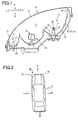
- Fig. 1 is a horizontal cross section of a vehicle headlight according to a first embodiment of the present invention, which is a cross section along line I-I in Fig. 3;
- Fig. 2 is a plan view of a vehicle indicating the used condition thereof;
- Fig. 3 is a view in the direction of arrow III in Fig. 2;
- Fig. 4 is a front elevational view of a reflector in a first lamp unit;
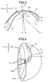
- Fig. 5 is a cross section obtained by combining a cross section along line V1-V1, a cross section along line V2-V2, and a cross section along line V3-V3 in Fig. 4;
- Fig. 6 is a view in the direction of arrow VI in Fig. 4;
- Fig. 7 is an explanatory diagram of a first bending light-distribution-pattern and a first condensing light-distribution-pattern;
- Fig. 8 is an explanatory diagram of the first bending light-distribution-pattern, the first condensing light-distribution-pattern, and a low-beam light-distribution-pattern;
- Fig. 9 is an explanatory diagram of a second bending light-distribution-pattern, a second condensing light-distribution-pattern, and a high-beam light-distribution-pattern;
- Fig. 10 is a horizontal cross section of a vehicle headlight according a second embodiment of the present invention, which is a cross section along line V1-V1 in Fig. 4;
- Fig. 11 is a cross section along line V3-V3 in Fig. 4; and
- Fig. 12 is a cross section along line V2-V2 in Fig. 4.
-
- Exemplary embodiments of a vehicle headlight according to the present invention will be explained in detail with reference to the accompanying drawings. However, the present invention is not limited to these embodiments. In schematic diagrams shown in Figs. 1, 5, and 10 to 12, a hatching is omitted.
- Figs. 1 to 9 depict a vehicle headlight according to a first embodiment of the present invention. The configuration of the vehicle headlight in the first embodiment will be explained first. In the drawings, reference sign "F" denotes the front side (traveling direction) of a vehicle C. Reference sign "B" denotes the back side of the vehicle C. Reference sign "I" denotes the inner side of the vehicle C. Reference sign "O" denotes the outer side of the vehicle C. Reference sign "U" denotes upward when a driver sees the front. Reference sign "D" denotes downward when the driver sees the front. Reference sign "L" denotes the left side when the driver sees the front. Reference sign "R" denotes the right side when the driver sees the front. Reference sign "VU-VD" denotes a vertical line on a screen. Reference sign "HL-HR" denotes a horizontal line on the screen.
- In Figs. 1 to 3,
reference signs headlights left headlight 1 L will be explained below. The configuration of theright headlight 1 R is substantially symmetric (reversed from left to right) to the configuration of theleft headlight 1 L. - The
headlight 1 L is a four-light headlight, and is a so-called front combination lamp. Theheadlight 1 L includes, as shown in Figs. 1 and 3, alamp housing 3 that sections alamp chamber 2, an outer lens (lamp lens or outer cover) 4, and afirst lamp unit 5, asecond lamp unit 6, and twosupplementary lamp units 7 arranged in thelamp chamber 2. - The
outer lens 4 is formed of a transparent or a substantially transparent lens. The horizontal cross section of theouter lens 4 has a slant or a curved shape back and forth from the inner side I to the outer side O of the vehicle C. On the other hand, thefirst lamp unit 5 is arranged on the inner side I of the vehicle C. Thesecond lamp unit 6 is arranged on the outer side O of the vehicle C. Further, the twosupplementary lamp units 7 are arranged on the outer side O of the vehicle C than thesecond lamp unit 6. - The
first lamp unit 5 is a traveling lamp unit, and includes alight source 8 and areflector 9 that reflects the light from thelight source 8 toward theouter lens 4 in a predetermined light distribution pattern. - The
light source 8 uses a so-called H4 bulb. That is, as shown in Fig. 1, thelight source 8 has afirst filament 11 corresponding to a subfilament, asecond filament 12 corresponding to a main filament, and ashade 10 that shades a part of light from thefirst filament 11, that is, light emitted toward asecond reflection surface 22. - The
reflector 9 has, as shown in Figs. 4 and 5, afirst reflection surface 21, athird reflection surface 23, and thesecond reflection surface 22 in order from above. That is, thefirst reflection surface 21 is arranged on the upper side, the second reflection surface is arranged on the lower side, and the third reflection surface is arranged between the first reflection surface and the second reflection surface. A substantially circular throughhole 20 is provided substantially at the center of thereflector 9. The throughhole 20 is for inserting thelight source 8 therethrough. Thefirst reflection surface 21, thesecond reflection surface 22, and thethird reflection surface 23 are divided into a plurality of numbers, respectively, that is, in this embodiment, into six segments horizontally. - The
first reflection surface 21 is designed for light distribution so that a first bending light-distribution-pattern BP1 (see Figs. 7 and 8) can be obtained by reflecting the light from thefirst filament 11 of thelight source 8. The first bending light-distribution-pattern BP1 is, as shown in Figs. 7 and 8, largely diffused to the left side from the vertical line VU-VD horizontally, and has a vertically large width downward from the horizontal line HL-HR. In other words, the first bending light-distribution-pattern BP1 is a light distribution pattern such that it extends outward from the center of the vehicle C. Therefore, the first bending light-distribution-pattern BP1 is suitable for widely illuminating the road surface and the like relatively on this side of the outer side O of the vehicle C, when the vehicle C is turning to the right or left at an intersection or at a corner, or traveling a curved road, at a low speed. The first bending light-distribution-pattern BP1 shown in Figs. 7 and 8 is irradiated by the left headlight 1 L. Therefore, the first bending light-distribution-pattern (not shown) irradiated by theright headlight 1 R is symmetric (reversed from left to right) to the first bending light-distribution-pattern BP1 shown in Figs. 7 and 8. - The
first reflection surface 21 is designed for light distribution so that a second bending light-distribution-pattern BP2 (see Fig. 9) can be obtained by reflecting the light from thesecond filament 12 of thelight source 8. The second bending light-distribution-pattern BP2 is, as shown in Fig. 9, largely diffused to the left side from the vertical line VU-VD horizontally, and has a vertically large width upward from the horizontal line HL-HR. In other words, the second bending light-distribution-pattern BP2 is a light distribution pattern such that it extends outward from the center of the vehicle C. Therefore, the second bending light-distribution-pattern BP2 is suitable for widely illuminating the road surface and the like relatively on the far side of the outer side O of the vehicle C, when the vehicle C is traveling a curved road at a high speed or traveling at a high speed. The second bending light-distribution-pattern BP2 shown in Fig. 9 is irradiated by the left headlight 1 L. Therefore, the second bending light-distribution-pattern (not shown) irradiated by theright headlight 1 R is symmetric (reversed from left to right) to the second bending light-distribution-pattern BP2 shown in Fig. 9. - The horizontal cross section of the
first reflection surface 21 has, as shown in Fig. 5, a shape opened to the outer side O of the vehicle C. That is, the optical axis Z1-Z1 of thefirst reflection surface 21 is directed to the outer side O of the vehicle C. As a result, thefirst reflection surface 21 is most suitable for obtaining the first bending light-distribution-pattern BP1 and the second bending light-distribution-pattern BP2. - Two left side segments 22L and two right side segments 22R of the
second reflection surface 22 are designed for light distribution so that a condensing light-distribution-pattern SHP (see Fig. 9) of the high-beam light-distribution-patterns can be obtained by reflecting the light from thesecond filament 12 of thelight source 8. The condensing light-distribution-pattern SHP of the high-beam light-distribution-patterns condenses rays of light, as shown in Fig. 9, vertically and horizontally, designating a point of intersection of the vertical line VU-VD and the horizontal line HL-HR as a substantial center. Therefore, the condensing light-distribution-pattern SHP of the high-beam light-distribution-patterns is suitable for illuminating the vicinity of a point at which the driver is looking, such as the road surface and the like on the front side F (the far side) of the vehicle C, when the vehicle C is traveling a curved road at a high speed or traveling at a high speed. The condensing light-distribution-pattern SHP of the high-beam light-distribution-patterns shown in Fig. 9 is irradiated by the left headlight 1 L. Therefore, the condensing light-distribution-pattern SHP (not shown) of the high-beam light-distribution-patterns irradiated by theright headlight 1 R has substantially the same shape as (or becomes symmetric to) the condensing light-distribution-pattern SHP of the high-beam light-distribution-patterns shown in Fig. 9. - Two segments 22C at the center of the
second reflection surface 22 are designed for light distribution so that the diffused light-distribution-pattern WHP (see Fig. 9) of the high-beam light-distribution-patterns can be obtained by reflecting the light from thesecond filament 12 of thelight source 8. The diffused light-distribution-pattern WHP of the high-beam light-distribution-patterns is diffused widely in the vertical and horizontal directions, designating a point of intersection of the vertical line VU-VD and the horizontal line HL-HR as a substantial center as shown in Fig. 9. Therefore, the diffused light-distribution-pattern WHP of the high-beam light-distribution-patterns is suitable for widely illuminating the road surface and the like on the front side F (the far side) of the vehicle C, when the vehicle C is traveling a curved road at a high speed or traveling at a high speed. The diffused light-distribution-pattern WHP of the high-beam Light-distribution-patterns shown in Fig. 9 is irradiated by the left headlight 1 L. Therefore, the diffused light-distribution-pattern WHP (not shown) of the high-beam light-distribution-patterns irradiated by theright headlight 1 R is substantially the same shape as (or becomes symmetric to) the diffused light-distribution-pattern WHP of the high-beam light-distribution-patterns shown in Fig. 9. - A part of the light from the
first filament 11 of thelight source 8 is shaded by theshade 10 so it does not enter into thesecond reflection surface 22. As a result, the light distribution pattern in which the light from thefirst filament 11 of thelight source 8 is reflected by thesecond reflection surface 22 cannot be obtained. - The horizontal cross section of the
second reflection surface 22 has, as shown in Fig. 5, a shape opened to the front side F of the vehicle C. That is, an optical axis Z2-Z2 of thesecond reflection surface 22 is directed to the front side F of the vehicle C. As a result, thesecond reflection surface 22 is most suitable for obtaining the condensing light-distribution-pattern SHP and the diffused light-distribution-pattern WHP of the high-beam light-distribution-patterns. - The
third reflection surface 23 is designed for light distribution so that a first condensing light-distribution-pattern SP1 (see Figs. 7 and 8) can be obtained by reflecting the light from thefirst filament 11 of thelight source 8. The first condensing light-distribution-pattern SP1 is, as shown in Figs. 7 and 8, slightly extended horizontally, designating the vertical line VU-VD as a substantial center, and has a small vertical width downward from the horizontal line HL-HR. Therefore, the first condensing light-distribution-pattern SP1 is suitable for illuminating near a cutline CL of the low-beam light-distribution-pattern LP and the vicinity of a point at which the driver is looking, when the vehicle C is traveling a curved road at a medium speed (40 to 60 km/h). The first condensing light-distribution-pattern SP1 shown in Figs. 7 and 8 is irradiated by the left headlight 1 L. Therefore, the first condensing light-distribution-pattern (not shown) irradiated by theright headlight 1 R is substantially the same shape as (or becomes symmetric to) the first condensing light-distribution-pattern SP1 shown in Figs. 7 and 8. The low-beam light-distribution-pattern LP shown in Fig. 8 is used for when the driving lane is on the left side. Therefore, the low-beam light-distribution-pattern when the driving lane is on the right side is symmetric (reversed from'left to right) to the low-beam light-distribution-pattern shown in Fig. 8. - The
third reflection surface 23 is designed for light distribution so that a second condensing light-distribution-pattern SP2 (see Fig. 9) can be obtained by reflecting the light from thesecond filament 12 of thelight source 8. The second condensing light-distribution-pattern SP2 is, as shown in Fig. 9, slightly extended vertically and horizontally, designating a point of intersection of the vertical line VU-VD and the horizontal line HL-HR as a substantial center. Therefore, the second condensing light-distribution-pattern SP2 is suitable for illuminating the road surface and the like on the front side F (far side) of the vehicle C, and the vicinity of a point at which the driver is looking, when the vehicle C is traveling a curved road at a high speed or traveling at a high speed. The second condensing light-distribution-pattern SP2 shown in Fig. 9 is irradiated by theleft headlight 1L. Therefore, a second bending light-distribution-pattern (not shown) irradiated by theright headlight 1 R is substantially the same shape as (or becomes symmetric to) the second condensing light-distribution-pattern SP2 shown in Fig. 9. - The horizontal cross section of the
third reflection surface 23 has, as shown in Fig. 5, a shape opened to the front side F and slightly toward the outer side O of the vehicle C. That is, an optical axis Z3-Z3 of thethird reflection surface 23 is directed to the front side F and slightly toward the outer side O of the vehicle C. As a result, thethird reflection surface 23 is most suitable for obtaining the first condensing light-distribution-pattern SP1 and the second condensing light-distribution-pattern SP2. The focal length of thethird reflection surface 23 is larger than that of thefirst reflection surface 21. As a result, the form of thethird reflection surface 23 can be approximated to the form of thefirst reflection surface 21. In other words, when thereflector 9 in thefirst lamp unit 5 is seen from the outer side O of the vehicle C, as shown in Fig. 6, thefirst reflection surface 21 and thesecond reflection surface 22 are smoothly continuous to each other via thethird reflection surface 23. - A focal point F1 of the
first reflection surface 21 and a focal point F3 of thethird reflection surface 23 are respectively positioned, as shown in Fig. 5, near thefirst filament 11 of thelight source 8. A focal point F2 of thereflection surface 22 is, for example as shown in Fig. 5, positioned near thesecond filament 12 of thelight source 8. The positions of the respective focal points F1, F2, and F3 of the respective reflection surfaces 21, 22, and 23 are not limited to the positions shown in Fig. 5. - The
second lamp unit 6 is a low-beam lamp unit, and has a low-beam light source 13 and a low-beam reflector 14 (a low-beam reflection surface) that reflects the light from the low-beam light source 13 toward theouter lens 4 on the front. Thesecond lamp unit 6 is, as shown in Fig. 8, for obtaining a predetermined low-beam light-distribution-pattern LP. For the low-beam light source 13, a single-filament halogen lamp or discharge lamp (a so-called high pressure metal vapor discharge lamp such as a metal halide lamp or a high intensity discharge lamp (HID)) is used. - The
supplementary lamp unit 7 is, for example, a front turn signal lamp or a front clearance lamp. Thesupplementary lamp unit 7 includes alight source 15 and a reflector (reflection surface) 16 that reflects the light from thelight source 15 and irradiates the light in a predetermined light distribution pattern. Anextension 17 is respectively arranged and secured between theouter lens 4 and thefirst lamp unit 5, and between theouter lens 4 and thesupplementary lamp unit 7. Theextension 17 is used for covering so that the structure at the back of therespective lamp units - The
first filament 11 and thesecond filament 12 of thefirst lamp unit 5, thelight source 13 of thesecond lamp unit 6, and thelight source 15 of thesupplementary lamp unit 7 are connected to any one of a manual switching device (not shown) and an automatic switching device (not shown) or both via a switching controller (not shown). - The switching controller includes a control circuit and an electrical control unit (ECU), and uses a computer equipped on a vehicle (vehicle). The manual switching device is a lamp switch switched by the driver. The automatic switching device automatically switches the
first filament 11 and thesecond filament 12 of thefirst lamp unit 5, thelight source 13 of thesecond lamp unit 6, and thelight source 15 of thesupplementary lamp unit 7 based on environment information around the vehicle C. A device that obtains the environment information around the vehicle C in the automatic switching device includes, for example, an indicator, a speed sensor, a rudder angle sensor, an illuminance sensor, a global positioning system (GPS) receiver, a gyro sensor, a wiper switch, a raindrop sensor, and an imaging device of a semiconductor device, such as a charge coupled device (CCD) camera and a complementary metal oxided semiconductor (CMOS) camera. - The vehicle headlight in the first embodiment has the above configuration, and the action thereof will be explained below.
- The
first filament 11 of thelight source 8 in thefirst lamp unit 5 is lighted in the left headlight 1 L. The light from thefirst filament 11 is reflected by thefirst reflection surface 21 and thethird reflection surface 23 of thereflector 9. The reflected light is irradiated to the outside as the first bending light-distribution-pattern BP1 and the first condensing light-distribution-pattern SP1 shown in Fig. 7, to illuminate the road surface and the like. When the first filament of the light source in the first lamp unit of theright headlight 1 R is lighted, a light distribution pattern symmetric (reversed from left to right) to the first bending light-distribution-pattern BP1 and the first condensing light-distribution-pattern SP1 shown in Fig. 7 can be obtained. - The
first filament 11 of thelight source 8 in thefirst lamp unit 5 of theleft headlight 1 L, and thelight source 13 in thesecond lamp unit 6 of the right and theleft headlights first filament 11 is reflected by thefirst reflection surface 21 and thethird reflection surface 23 of thereflector 9. At the same time, the light from thelight source 13 in thesecond lamp unit 6 is reflected by thereflector 14. The reflected light is irradiated to the outside as the first bending light-distribution-pattern BP1, the first condensing light-distribution-pattern SP1, and the low-beam light-distribution-pattern LP shown in Fig. 8, to illuminate the road surface and the like. When the first filament of the light source in the first lamp unit of theright headlight 1 R is lighted, a light distribution pattern symmetric (reversed from left to right) to the first bending light-distribution-pattern BP1 and the first condensing light-distribution-pattern SP1 shown in Fig. 8 can be obtained, together with the low-beam light-distribution-pattern LP shown in Fig. 8. - In the
left headlight 1 L, thesecond filament 12 of thelight source 8 in thefirst lamp unit 5 is lighted. The light from thesecond filament 12 is reflected by thefirst reflection surface 21, thesecond reflection surface 22, and thethird reflection surface 23 of thereflector 9. The reflected light is irradiated to the outside as the second bending light-distribution-pattern BP2, the second condensing light-distribution-pattern SP2, and the high-beam light-distribution-patterns SHP and WHP shown in Fig. 9, to illuminate the road surface and the like. When the second filament of the light source in the first lamp unit of theright headlight 1 R is lighted, a light distribution pattern symmetric (reversed from left to right) to the second bending light-distribution-pattern BP2, the second condensing light-distribution-pattern SP2, and the high-beam light-distribution-patterns SHP and WHP shown in Fig. 9 can be obtained. When thesecond filaments 12 of thelight sources 8 in thefirst lamp units 5 of the right and theleft headlights - When the
light sources 13 in thesecond lamp units 6 of the right and theleft headlights light sources 15 in thesupplementary lamp units 7 of the right and theleft headlights - The vehicle headlight in the first embodiment has the above configuration and action, and the effects thereof will be explained below.
- The
headlights first filament 11 of thelight source 8, and the second condensing light-distribution-pattern SP2 by reflecting the light from thesecond filament 12 of thelight source 8, by thethird reflection surface 23. That is, theheadlights third reflection surface 23. Therefore, theheadlights first reflection surface 21, by the first condensing light-distribution-pattern SP1 and the second condensing light-distribution-pattern SP2 obtained by thethird reflection surface 23, as well as improving the light distribution performance of the high-beam light-distribution-patterns SHP and WHP obtained by thesecond reflection surface 22. As a result, theheadlights - Particularly, in the
headlights third reflection surface 23 is arranged between thefirst reflection surface 21 and thesecond reflection surface 22, and the focal length of thethird reflection surface 23 is larger than that of thefirst reflection surface 21. Therefore, in theheadlights third reflection surface 23 can be approximated to the form of thefirst reflection surface 21, and hence, thefirst reflection surface 21 and thesecond reflection surface 22 are smoothly continuous to each other via thethird reflection surface 23. As a result, when the side of thereflector 9 in thefirst lamp unit 5 is seen from the outer side O of the vehicle C, theheadlights - In the
headlights first reflection surface 21 has a shape opened to the outer side O of the vehicle C, the horizontal cross section of thesecond reflection surface 22 has a shape opened to the front side F of the vehicle C, and the horizontal cross section of thethird reflection surface 23 has a shape opened to the front side F and slightly toward the outer side O of the vehicle C, so that thefirst reflection surface 21 and thesecond reflection surface 22 are made smoothly continuous to each other. Therefore, theheadlights headlights first filament 11 of thelight source 8 passes through thefirst reflection surface 21 and the edge of thethird reflection surface 23 of thereflector 9, and is irradiated to the outer side O of the vehicle C. Accordingly, the visibility at the time of turning to the right or the left at an intersection or at a corner, or traveling on a curved road can be improved. In addition, in theheadlights first reflection surface 21 and thesecond reflection surface 22 are smoothly continuous via thethird reflection surface 23, the appearance can be further improved. - In the
headlights outer lens 4 has a slant or a curved shape back and forth from the inner side I toward the outer side O of the vehicle C, thefirst lamp unit 5 is arranged on the inner side I of the vehicle C, and thesecond lamp unit 6 is arranged on the outer side O of the vehicle C. Therefore, in theheadlights first lamp unit 5 can be fully demonstrated, and the light distribution performance of thesecond lamp unit 6 can be maintained high, while ensuring a shape that does not spoil the design. - In other words, when the arrangement of the
first lamp unit 5 is changed to that of thesecond lamp unit 6, the diffused light emitted from thefirst lamp unit 5 toward the outer side O of the vehicle C is blocked by thesupplementary lamp unit 7, and hence the performance of the bending light-distribution-patterns BP1 and BP2 of thefirst lamp unit 5 cannot be fully demonstrated. The diffused light from thesecond lamp unit 6 is also blocked by theheadlights lamp housing 3, to decrease the light distribution performance. Further, the diffused light from thesecond lamp unit 6 is shone on theextensions 17 and reflected thereby, and the reflected light causes an optical line or optical unevenness on the road surface and the like, to decrease the commercial value of the headlight. However, theheadlights - When the arrangement of the
first lamp unit 5 is changed to that of thesupplementary lamp unit 7, the distance between thefirst lamp unit 5 and theouter lens 4 becomes short, and hence the side of thefirst lamp unit 5 becomes noticeable, which is not desirable in view of the design. However, theheadlights - Figs. 10 to 12 respectively depict a vehicle headlight according to a second embodiment of the present invention. The configuration of the vehicle headlight in the second embodiment will be explained below. In these drawings, like reference signs designate to like parts in Figs. 1 to 9.
- In the second embodiment, the horizontal cross section of the
first reflection surface 21 has, as shown in Fig. 10, a shape opened to the outer side O of the vehicle C, as in the first embodiment. That is, the optical axis Z1-Z1 of thefirst reflection surface 21 is directed toward the outer side O of the vehicle C, by appropriately rotating it (for example, in this embodiment, 50 to 60 degrees) in a counterclockwise direction with respect to the optical axis Z2-Z2 of thesecond reflection surface 22 and the optical axis Z3-Z3 of the third reflection surfaces 23O and 23l, about the focal point F1 of thefirst reflection surface 21. As a result, thefirst reflection surface 21 reflects the light from thefirst filament 11 of thelight source 8 to obtain the first bending light-distribution-pattern BP1, and reflects the light from thesecond filament 12 of thelight source 8 to obtain the second bending light-distribution-pattern BP2. The first bending light-distribution-pattern BP1 and the second bending light-distribution-pattern BP2 are light distribution patterns expanding from the center toward the outer side of the vehicle C. - In the second embodiment, as shown in Fig. 12, the horizontal cross section of the
second reflection surface 22 has a shape opened to the front side F of the vehicle C, as in the first embodiment. That is, the optical axis Z2-Z2 of thesecond reflection surface 22 is directed toward the front side F of the vehicle C. As a result, thesecond reflection surface 22 reflects the light from thesecond filament 12 of thelight source 8 to obtain the condensing light-distribution-pattern SHP and the diffused light-distribution-pattern WHP of the high-beam light-distribution-patterns. - Furthermore, in the second embodiment, the horizontal cross section of the third reflection surfaces 23O and 23l has a shape opened to the front side F of the vehicle C, as shown in Fig. 11. That is, the optical axis Z3-Z3 of the third reflection surfaces 23O and 23l are directed toward the front side F of the vehicle C, substantially agreeing with the optical axis Z2-Z2 of the
second reflection surface 22. The third reflection surface is divided into aportion 230 on the outer side of the vehicle and a portion 23l on the inner side of the vehicle. The focal length of the third reflection surface in theportion 230 on the outer side of the vehicle is larger than that of the portion 23l on the inner side of the vehicle. The basic reflection surface of the third reflection surfaces 23O and 23l is first designed, designating thefirst filament 11 of thelight source 8 as the focal point F3, and then a reflection surface of a free-form surface is designed so that the light from thefirst filament 11 and the light from thesecond filament 12 of thelight source 8 are reflected to obtain the predetermined first condensing light-distribution-pattern SP1 and the second condensing light-distribution-pattern SP2. As a result, the third reflection surfaces 23O and 23l reflect the light from thefirst filament 11 of thelight source 8 to obtain the first condensing light-distribution-pattern SP1 and reflect the light from thesecond filament 12 of thelight source 8 to obtain the second condensing light-distribution-pattern SP2. In the third reflection surface, a point of division between the portion 23O on the outer side of the vehicle and the portion 23l on the inner side of the vehicle is located on a vertical line passing through the optical axis Z3-Z3 of the third reflection surfaces 23O and 23l, although it is not shown in the figure. - The vehicle headlight in the second embodiment can achieve the action and effects similar to those of the vehicle headlight in the first embodiment.
- Particularly, in the vehicle headlight in the second embodiment, the focal length of the third reflection surface in the
portion 230 on the outer side of the vehicle is larger than that of the portion 23l on the inner side of the vehicle. As a result, the form of theportion 230 on the outer side of the vehicle of the third reflection surface can be approximated to the form of the portion on the outer side O of the vehicle of thefirst reflection surface 21, while the form of the portion 23l on the inner side of the vehicle of the third reflection surface can be approximated to the form of the portion on the inner side I of the vehicle of thefirst reflection surface 21. As a result, when thereflector 9 in thefirst lamp unit 5 is seen from the outer side O of the vehicle C, as shown in Fig. 6, thefirst reflection surface 21 and thesecond reflection surface 22 are smoothly continuous to each other via the third reflection surface 23 (23O, 23l). - Although the invention has been described with respect to a specific embodiment for a complete and clear disclosure, the appended claims are not to be thus limited but are to be construed as embodying all modifications and alternative constructions that may occur to one skilled in the art which fairly fall within the basic teaching herein set forth.
Claims (11)
- A four-light-type vehicle headlight comprising a first lamp unit (5) and a second lamp unit (6), wherein
the first lamp unit (5) includesthe light source (8) includesa light source (8); anda reflector (9) that reflects light from the light source (8) in a predetermined light distribution pattern,the reflector (9) includesa first filament (11);a second filament (12); anda shade (10) that shades a part of light from the first filament (11), anda first reflection surface (21) that reflects the light from the first filament (11) to obtain a first bending light-distribution-pattern, and reflects light from the second filament (12) to obtain a second bending light-distribution-pattern;a second reflection surface (22) that reflects the light from the second filament (12) to obtain a high-beam light-distribution-pattern, in which the light from the first filament (11) is shaded by the shade (10); anda third reflection surface (23) that reflects the light from the first filament (11) to obtain a first condensing light-distribution-pattern, and reflects the light from the second filament (12) to obtain a second condensing light-distribution-pattern. - The vehicle headlight according to claim 1, wherein
the third reflection surface (23) is arranged between the first reflection surface (21) and the second reflection surface (22), and
a focal length of the third reflection surface (23) is longer than a focal length of the first reflection surface (21). - The vehicle headlight according to claim 1, wherein
the first reflection surface (21) is arranged on an upper side, and is divided into a plurality of segments horizontally,
the second reflection surface (22) is arranged on a lower side, and is divided into a plurality of segments horizontally,
the third reflection surface (23) is arranged between the first reflection surface (21) and the second reflection surface (22), and is divided into a plurality of segments horizontally, and
a focal length of the third reflection surface (23) is longer than a focal length of the first reflection surface (21). - The vehicle headlight according to claim 1, wherein
a horizontal cross section of the first reflection surface (21) has a shape opened to an outer side of the vehicle,
a horizontal cross section of the second reflection surface (22) has a shape opened to a front side of the vehicle, and
a horizontal cross section of the third reflection surface (23) has a shape opened to the front side of the vehicle and slightly toward the outer side of the vehicle. - The vehicle headlight according to claim 1, wherein
the first reflection surface (21) is arranged on an upper side, and is divided into a plurality of segments horizontally,
the second reflection surface (22) is arranged on a lower side, and is divided into a plurality of segments horizontally,
the third reflection surface (23) is arranged between the first reflection surface (21) and the second reflection surface (22), and is divided into a plurality of segments horizontally,
a horizontal cross section of the first reflection surface (21) has a shape opened to an outer side of the vehicle,
a horizontal cross section of the second reflection surface (22) has a shape opened to a front side of the vehicle, and
a horizontal cross section of the third reflection surface (23) has a shape opened to the front side of the vehicle and slightly toward the outer side of the vehicle - The vehicle headlight according to claim 1, wherein
the second lamp unit (6) obtains a low-beam light-distribution-pattern,
the first lamp unit (5) and the second lamp unit (6) are arranged in a lamp chamber (2) zoned by a lamp housing (3) and an outer lens (4),
the horizontal cross section of the outer lens (4) has a slant or a curved shape back and forth from an inner side toward an outer side of the vehicle,
the first lamp unit (5) is arranged on the inner side of the vehicle, and
the second lamp unit (6) is arranged on the outer side of the vehicle. - The vehicle headlight according to claim 1, wherein
the second lamp unit (6) obtains a low-beam light-distribution-pattern and a high-beam light-distribution-pattern in a switchable manner,
the first lamp unit (5) and the second lamp unit (6) are arranged in a lamp chamber (2) zoned by a lamp housing (3) and an outer lens (4),
the horizontal cross section of the outer lens (4) has a slant or a curved shape back and forth from an inner side toward an outer side of the vehicle,
the first lamp unit (5) is arranged on the inner side of the vehicle, and
the second lamp unit (6) is arranged on the outer side of the vehicle. - The vehicle headlight according to claim 1, wherein
the second reflection surface (22) is divided horizontally into at least three segments, and includes right and left segments that obtain a condensing light-distribution-pattern, and
a central segment that obtains a diffused light-distribution-pattern in the high-beam light-distribution-patterns. - The vehicle headlight according to claim 1, wherein the first filament (11) and the second filament (12) in the first lamp unit (5) and a light source (13) in the second lamp unit (6) are connected to a manual switching device via a switching controller.
- The vehicle headlight according to claim 1, wherein the first filament (11) and the second filament (12) in the first lamp unit (5) and a light source (13) in the second lamp unit (6) are connected to an automatic switching device via a switching controller.
- The vehicle headlight according to claim 1, wherein
a horizontal cross section of the first reflection surface (21) has a shape opened to an outer side of the vehicle,
a horizontal cross section of the second reflection surface (22) and a horizontal cross section of the third reflection surface (23) have shapes opened to a front side of the vehicle,
the third reflection surface (23) is divided into a portion on the outer side of the vehicle and an inner portion of the vehicle, and
a focal length of the third reflection surface (23) in the portion on the outer side of the vehicle is longer than a focal length of the third reflection surface (23) in the inner portion of the vehicle.
Applications Claiming Priority (4)
| Application Number | Priority Date | Filing Date | Title |
|---|---|---|---|
| JP2003402126 | 2003-12-01 | ||
| JP2003402126 | 2003-12-01 | ||
| JP2004322666 | 2004-11-05 | ||
| JP2004322666A JP2005190990A (en) | 2003-12-01 | 2004-11-05 | Head lamp for automobile |
Publications (3)
| Publication Number | Publication Date |
|---|---|
| EP1538021A2 true EP1538021A2 (en) | 2005-06-08 |
| EP1538021A3 EP1538021A3 (en) | 2006-11-02 |
| EP1538021B1 EP1538021B1 (en) | 2008-02-20 |
Family
ID=34467837
Family Applications (1)
| Application Number | Title | Priority Date | Filing Date |
|---|---|---|---|
| EP04028379A Expired - Fee Related EP1538021B1 (en) | 2003-12-01 | 2004-11-30 | Vehicle headlight |
Country Status (4)
| Country | Link |
|---|---|
| US (1) | US7144143B2 (en) |
| EP (1) | EP1538021B1 (en) |
| JP (1) | JP2005190990A (en) |
| DE (1) | DE602004011883T2 (en) |
Cited By (1)
| Publication number | Priority date | Publication date | Assignee | Title |
|---|---|---|---|---|
| EP2159479A3 (en) * | 2008-08-27 | 2011-03-30 | Koito Manufacturing Co., Ltd. | Vehicle lamp unit |
Families Citing this family (8)
| Publication number | Priority date | Publication date | Assignee | Title |
|---|---|---|---|---|
| US7625109B2 (en) * | 2005-06-30 | 2009-12-01 | Koito Manufacturing Co., Ltd. | Vehicle lamp |
| CZ302547B6 (en) * | 2005-07-04 | 2011-07-07 | Visteon Global Technologies, Inc. | Adaptive headlight system of motor vehicles |
| DE102008021688A1 (en) * | 2008-04-30 | 2009-11-05 | Hella Kgaa Hueck & Co. | Vehicle's e.g. passenger car, exterior lighting controlling method, involves performing automatic switching-off of headlamp and switching-on of light by controller when environment brightness is larger than prior fixed minimum value |
| JP5245814B2 (en) * | 2008-12-26 | 2013-07-24 | 市光工業株式会社 | Vehicle lighting |
| US8444306B2 (en) | 2010-12-20 | 2013-05-21 | Caterpillar Inc. | Vocational truck headlight assembly |
| CN104203736B (en) * | 2012-03-29 | 2016-08-24 | 本田技研工业株式会社 | The head lamp device of two-wheeled motor vehicle |
| JP6162543B2 (en) * | 2013-08-23 | 2017-07-12 | スタンレー電気株式会社 | Vehicle headlamp |
| AT516965B1 (en) * | 2015-03-25 | 2016-12-15 | Zkw Group Gmbh | Lighting device for vehicle headlights |
Citations (3)
| Publication number | Priority date | Publication date | Assignee | Title |
|---|---|---|---|---|
| US4697225A (en) * | 1985-08-31 | 1987-09-29 | Robert Bosch Gmbh | Headlamp, particularly of rectangular configuration, for use as antidazzle lamp on motor vehicles |
| DE10014301A1 (en) * | 1999-03-26 | 2000-10-12 | Koito Mfg Co Ltd | Vehicle headlamp arrangement uses light from second section to variably expand base light distribution to alter quantity of light or colour depending on driving situation or environment |
| US6402355B1 (en) * | 1999-08-19 | 2002-06-11 | Koito Manufacturing Co., Ltd. | Vehicular headlamp having improved low-beam illumination |
Family Cites Families (5)
| Publication number | Priority date | Publication date | Assignee | Title |
|---|---|---|---|---|
| JPS62163201A (en) | 1986-01-10 | 1987-07-20 | 日産自動車株式会社 | Head lamp for vehicle |
| JPH07109721B2 (en) * | 1990-08-07 | 1995-11-22 | 株式会社小糸製作所 | Vehicle headlights |
| US6630770B1 (en) * | 1998-11-20 | 2003-10-07 | Ichikoh Industries, Ltd. | Automotive headlamp with support wire positioning |
| JP2001202805A (en) * | 2000-01-14 | 2001-07-27 | Stanley Electric Co Ltd | Lighting fixture |
| JP2003025906A (en) | 2001-07-17 | 2003-01-29 | Ichikoh Ind Ltd | Head lamp device |
-
2004
- 2004-11-05 JP JP2004322666A patent/JP2005190990A/en active Pending
- 2004-11-30 EP EP04028379A patent/EP1538021B1/en not_active Expired - Fee Related
- 2004-11-30 DE DE602004011883T patent/DE602004011883T2/en active Active
- 2004-12-01 US US11/000,502 patent/US7144143B2/en not_active Expired - Fee Related
Patent Citations (3)
| Publication number | Priority date | Publication date | Assignee | Title |
|---|---|---|---|---|
| US4697225A (en) * | 1985-08-31 | 1987-09-29 | Robert Bosch Gmbh | Headlamp, particularly of rectangular configuration, for use as antidazzle lamp on motor vehicles |
| DE10014301A1 (en) * | 1999-03-26 | 2000-10-12 | Koito Mfg Co Ltd | Vehicle headlamp arrangement uses light from second section to variably expand base light distribution to alter quantity of light or colour depending on driving situation or environment |
| US6402355B1 (en) * | 1999-08-19 | 2002-06-11 | Koito Manufacturing Co., Ltd. | Vehicular headlamp having improved low-beam illumination |
Cited By (1)
| Publication number | Priority date | Publication date | Assignee | Title |
|---|---|---|---|---|
| EP2159479A3 (en) * | 2008-08-27 | 2011-03-30 | Koito Manufacturing Co., Ltd. | Vehicle lamp unit |
Also Published As
| Publication number | Publication date |
|---|---|
| DE602004011883T2 (en) | 2009-02-12 |
| US7144143B2 (en) | 2006-12-05 |
| EP1538021B1 (en) | 2008-02-20 |
| DE602004011883D1 (en) | 2008-04-03 |
| JP2005190990A (en) | 2005-07-14 |
| US20050128765A1 (en) | 2005-06-16 |
| EP1538021A3 (en) | 2006-11-02 |
Similar Documents
| Publication | Publication Date | Title |
|---|---|---|
| US7690826B2 (en) | Adaptive front light system using LED headlamp | |
| EP2366940B1 (en) | Motorcycle projector headlight | |
| JP2001195910A (en) | Headlight for vehicle | |
| GB2352801A (en) | Vehicle headlamp | |
| US20120140503A1 (en) | Head Lamp for Vehicle | |
| US6457850B2 (en) | Vehicle lamp | |
| JP2019522336A (en) | High beam / low beam integrated headlamp module with LED light source with ADB function | |
| JP3553471B2 (en) | Vehicle headlights | |
| US6644828B2 (en) | Vehicular headlamp | |
| EP1538021B1 (en) | Vehicle headlight | |
| US7178958B2 (en) | Vehicle light | |
| JP2010235108A (en) | Headlight device for vehicle | |
| JP2002367416A (en) | Headlamp | |
| US7722210B2 (en) | Automotive lamp and reflector for low beam and advanced forward lighting system | |
| US7661861B2 (en) | Vehicle headlamp | |
| US6328463B1 (en) | Automobile headlamp | |
| US20010002879A1 (en) | Vehicular headlamp and vehicle provided with same | |
| JP4103440B2 (en) | Vehicle lighting | |
| US20090316415A1 (en) | Lamp unit | |
| KR100679626B1 (en) | Projection lamp for vehicle having structure for illumination of cut-off boundary area | |
| JP2001351411A (en) | Fog lamp for vehicle | |
| JP2009211854A (en) | Vehicle headlight | |
| CN106969306B (en) | The luminous vertical type lighting device in side for motor vehicles | |
| JP2005317465A (en) | Vehicular headlight | |
| JPS6026401Y2 (en) | vehicle head lamp |
Legal Events
| Date | Code | Title | Description |
|---|---|---|---|
| PUAI | Public reference made under article 153(3) epc to a published international application that has entered the european phase |
Free format text: ORIGINAL CODE: 0009012 |
|
| AK | Designated contracting states |
Kind code of ref document: A2 Designated state(s): AT BE BG CH CY CZ DE DK EE ES FI FR GB GR HU IE IS IT LI LU MC NL PL PT RO SE SI SK TR |
|
| AX | Request for extension of the european patent |
Extension state: AL HR LT LV MK YU |
|
| PUAL | Search report despatched |
Free format text: ORIGINAL CODE: 0009013 |
|
| AK | Designated contracting states |
Kind code of ref document: A3 Designated state(s): AT BE BG CH CY CZ DE DK EE ES FI FR GB GR HU IE IS IT LI LU MC NL PL PT RO SE SI SK TR |
|
| AX | Request for extension of the european patent |
Extension state: AL HR LT LV MK YU |
|
| 17P | Request for examination filed |
Effective date: 20061103 |
|
| 17Q | First examination report despatched |
Effective date: 20061222 |
|
| AKX | Designation fees paid |
Designated state(s): DE FR GB |
|
| GRAP | Despatch of communication of intention to grant a patent |
Free format text: ORIGINAL CODE: EPIDOSNIGR1 |
|
| RIN1 | Information on inventor provided before grant (corrected) |
Inventor name: MATSUMOTO, KAZUHIROC/O ICHIKOH INDUSTRIES, LTD. |
|
| GRAS | Grant fee paid |
Free format text: ORIGINAL CODE: EPIDOSNIGR3 |
|
| GRAA | (expected) grant |
Free format text: ORIGINAL CODE: 0009210 |
|
| AK | Designated contracting states |
Kind code of ref document: B1 Designated state(s): DE FR GB |
|
| REG | Reference to a national code |
Ref country code: GB Ref legal event code: FG4D |
|
| REF | Corresponds to: |
Ref document number: 602004011883 Country of ref document: DE Date of ref document: 20080403 Kind code of ref document: P |
|
| ET | Fr: translation filed | ||
| PLBE | No opposition filed within time limit |
Free format text: ORIGINAL CODE: 0009261 |
|
| STAA | Information on the status of an ep patent application or granted ep patent |
Free format text: STATUS: NO OPPOSITION FILED WITHIN TIME LIMIT |
|
| 26N | No opposition filed |
Effective date: 20081121 |
|
| PGFP | Annual fee paid to national office [announced via postgrant information from national office to epo] |
Ref country code: FR Payment date: 20121130 Year of fee payment: 9 Ref country code: DE Payment date: 20121128 Year of fee payment: 9 |
|
| PGFP | Annual fee paid to national office [announced via postgrant information from national office to epo] |
Ref country code: GB Payment date: 20121128 Year of fee payment: 9 |
|
| GBPC | Gb: european patent ceased through non-payment of renewal fee |
Effective date: 20131130 |
|
| REG | Reference to a national code |
Ref country code: FR Ref legal event code: ST Effective date: 20140731 |
|
| REG | Reference to a national code |
Ref country code: DE Ref legal event code: R119 Ref document number: 602004011883 Country of ref document: DE Effective date: 20140603 |
|
| PG25 | Lapsed in a contracting state [announced via postgrant information from national office to epo] |
Ref country code: DE Free format text: LAPSE BECAUSE OF NON-PAYMENT OF DUE FEES Effective date: 20140603 |
|
| PG25 | Lapsed in a contracting state [announced via postgrant information from national office to epo] |
Ref country code: GB Free format text: LAPSE BECAUSE OF NON-PAYMENT OF DUE FEES Effective date: 20131130 Ref country code: FR Free format text: LAPSE BECAUSE OF NON-PAYMENT OF DUE FEES Effective date: 20131202 |