EP1537993B1 - Verfahren zur Herstellung einer Schichtstruktur und mit einer solchen Struktur ausgestattetes Flugzeug - Google Patents
Verfahren zur Herstellung einer Schichtstruktur und mit einer solchen Struktur ausgestattetes Flugzeug Download PDFInfo
- Publication number
- EP1537993B1 EP1537993B1 EP04300814A EP04300814A EP1537993B1 EP 1537993 B1 EP1537993 B1 EP 1537993B1 EP 04300814 A EP04300814 A EP 04300814A EP 04300814 A EP04300814 A EP 04300814A EP 1537993 B1 EP1537993 B1 EP 1537993B1
- Authority
- EP
- European Patent Office
- Prior art keywords
- fastener
- panel
- diameter
- bore
- stack
- Prior art date
- Legal status (The legal status is an assumption and is not a legal conclusion. Google has not performed a legal analysis and makes no representation as to the accuracy of the status listed.)
- Expired - Lifetime
Links
- 238000000034 method Methods 0.000 title claims abstract description 17
- 229910052751 metal Inorganic materials 0.000 claims description 23
- 239000002184 metal Substances 0.000 claims description 23
- 239000002131 composite material Substances 0.000 claims description 13
- 229910052782 aluminium Inorganic materials 0.000 claims description 3
- XAGFODPZIPBFFR-UHFFFAOYSA-N aluminium Chemical group [Al] XAGFODPZIPBFFR-UHFFFAOYSA-N 0.000 claims description 3
- 238000005553 drilling Methods 0.000 claims description 3
- 229920000049 Carbon (fiber) Polymers 0.000 claims description 2
- 239000004917 carbon fiber Substances 0.000 claims description 2
- VNWKTOKETHGBQD-UHFFFAOYSA-N methane Chemical compound C VNWKTOKETHGBQD-UHFFFAOYSA-N 0.000 claims description 2
- 230000032798 delamination Effects 0.000 description 7
- 241000283707 Capra Species 0.000 description 3
- 238000004519 manufacturing process Methods 0.000 description 3
- OKTJSMMVPCPJKN-UHFFFAOYSA-N Carbon Chemical compound [C] OKTJSMMVPCPJKN-UHFFFAOYSA-N 0.000 description 2
- 229910052799 carbon Inorganic materials 0.000 description 2
- 230000000694 effects Effects 0.000 description 2
- 238000003780 insertion Methods 0.000 description 2
- 230000037431 insertion Effects 0.000 description 2
- 230000000712 assembly Effects 0.000 description 1
- 238000000429 assembly Methods 0.000 description 1
- 230000009286 beneficial effect Effects 0.000 description 1
- 238000010276 construction Methods 0.000 description 1
- 238000002788 crimping Methods 0.000 description 1
- 230000006378 damage Effects 0.000 description 1
- 230000007423 decrease Effects 0.000 description 1
- 230000001419 dependent effect Effects 0.000 description 1
- 230000001627 detrimental effect Effects 0.000 description 1
- 238000012423 maintenance Methods 0.000 description 1
- 230000003313 weakening effect Effects 0.000 description 1
- 230000004584 weight gain Effects 0.000 description 1
- 235000019786 weight gain Nutrition 0.000 description 1
Images
Classifications
-
- F—MECHANICAL ENGINEERING; LIGHTING; HEATING; WEAPONS; BLASTING
- F16—ENGINEERING ELEMENTS AND UNITS; GENERAL MEASURES FOR PRODUCING AND MAINTAINING EFFECTIVE FUNCTIONING OF MACHINES OR INSTALLATIONS; THERMAL INSULATION IN GENERAL
- F16B—DEVICES FOR FASTENING OR SECURING CONSTRUCTIONAL ELEMENTS OR MACHINE PARTS TOGETHER, e.g. NAILS, BOLTS, CIRCLIPS, CLAMPS, CLIPS OR WEDGES; JOINTS OR JOINTING
- F16B5/00—Joining sheets or plates, e.g. panels, to one another or to strips or bars parallel to them
- F16B5/02—Joining sheets or plates, e.g. panels, to one another or to strips or bars parallel to them by means of fastening members using screw-thread
- F16B5/025—Joining sheets or plates, e.g. panels, to one another or to strips or bars parallel to them by means of fastening members using screw-thread specially designed to compensate for misalignement or to eliminate unwanted play
-
- B—PERFORMING OPERATIONS; TRANSPORTING
- B64—AIRCRAFT; AVIATION; COSMONAUTICS
- B64C—AEROPLANES; HELICOPTERS
- B64C1/00—Fuselages; Constructional features common to fuselages, wings, stabilising surfaces or the like
- B64C1/06—Frames; Stringers; Longerons ; Fuselage sections
-
- B—PERFORMING OPERATIONS; TRANSPORTING
- B64—AIRCRAFT; AVIATION; COSMONAUTICS
- B64C—AEROPLANES; HELICOPTERS
- B64C1/00—Fuselages; Constructional features common to fuselages, wings, stabilising surfaces or the like
- B64C1/06—Frames; Stringers; Longerons ; Fuselage sections
- B64C1/12—Construction or attachment of skin panels
-
- B—PERFORMING OPERATIONS; TRANSPORTING
- B64—AIRCRAFT; AVIATION; COSMONAUTICS
- B64C—AEROPLANES; HELICOPTERS
- B64C1/00—Fuselages; Constructional features common to fuselages, wings, stabilising surfaces or the like
- B64C1/26—Attaching the wing or tail units or stabilising surfaces
-
- F—MECHANICAL ENGINEERING; LIGHTING; HEATING; WEAPONS; BLASTING
- F16—ENGINEERING ELEMENTS AND UNITS; GENERAL MEASURES FOR PRODUCING AND MAINTAINING EFFECTIVE FUNCTIONING OF MACHINES OR INSTALLATIONS; THERMAL INSULATION IN GENERAL
- F16B—DEVICES FOR FASTENING OR SECURING CONSTRUCTIONAL ELEMENTS OR MACHINE PARTS TOGETHER, e.g. NAILS, BOLTS, CIRCLIPS, CLAMPS, CLIPS OR WEDGES; JOINTS OR JOINTING
- F16B4/00—Shrinkage connections, e.g. assembled with the parts at different temperature; Force fits; Non-releasable friction-grip fastenings
- F16B4/004—Press fits, force fits, interference fits, i.e. fits without heat or chemical treatment
-
- F—MECHANICAL ENGINEERING; LIGHTING; HEATING; WEAPONS; BLASTING
- F16—ENGINEERING ELEMENTS AND UNITS; GENERAL MEASURES FOR PRODUCING AND MAINTAINING EFFECTIVE FUNCTIONING OF MACHINES OR INSTALLATIONS; THERMAL INSULATION IN GENERAL
- F16B—DEVICES FOR FASTENING OR SECURING CONSTRUCTIONAL ELEMENTS OR MACHINE PARTS TOGETHER, e.g. NAILS, BOLTS, CIRCLIPS, CLAMPS, CLIPS OR WEDGES; JOINTS OR JOINTING
- F16B5/00—Joining sheets or plates, e.g. panels, to one another or to strips or bars parallel to them
- F16B5/04—Joining sheets or plates, e.g. panels, to one another or to strips or bars parallel to them by means of riveting
-
- B—PERFORMING OPERATIONS; TRANSPORTING
- B64—AIRCRAFT; AVIATION; COSMONAUTICS
- B64C—AEROPLANES; HELICOPTERS
- B64C1/00—Fuselages; Constructional features common to fuselages, wings, stabilising surfaces or the like
- B64C2001/0054—Fuselage structures substantially made from particular materials
- B64C2001/0072—Fuselage structures substantially made from particular materials from composite materials
-
- B—PERFORMING OPERATIONS; TRANSPORTING
- B64—AIRCRAFT; AVIATION; COSMONAUTICS
- B64C—AEROPLANES; HELICOPTERS
- B64C1/00—Fuselages; Constructional features common to fuselages, wings, stabilising surfaces or the like
- B64C2001/0054—Fuselage structures substantially made from particular materials
- B64C2001/0081—Fuselage structures substantially made from particular materials from metallic materials
-
- Y—GENERAL TAGGING OF NEW TECHNOLOGICAL DEVELOPMENTS; GENERAL TAGGING OF CROSS-SECTIONAL TECHNOLOGIES SPANNING OVER SEVERAL SECTIONS OF THE IPC; TECHNICAL SUBJECTS COVERED BY FORMER USPC CROSS-REFERENCE ART COLLECTIONS [XRACs] AND DIGESTS
- Y02—TECHNOLOGIES OR APPLICATIONS FOR MITIGATION OR ADAPTATION AGAINST CLIMATE CHANGE
- Y02T—CLIMATE CHANGE MITIGATION TECHNOLOGIES RELATED TO TRANSPORTATION
- Y02T50/00—Aeronautics or air transport
- Y02T50/40—Weight reduction
-
- Y—GENERAL TAGGING OF NEW TECHNOLOGICAL DEVELOPMENTS; GENERAL TAGGING OF CROSS-SECTIONAL TECHNOLOGIES SPANNING OVER SEVERAL SECTIONS OF THE IPC; TECHNICAL SUBJECTS COVERED BY FORMER USPC CROSS-REFERENCE ART COLLECTIONS [XRACs] AND DIGESTS
- Y10—TECHNICAL SUBJECTS COVERED BY FORMER USPC
- Y10T—TECHNICAL SUBJECTS COVERED BY FORMER US CLASSIFICATION
- Y10T29/00—Metal working
- Y10T29/49—Method of mechanical manufacture
- Y10T29/49616—Structural member making
- Y10T29/49622—Vehicular structural member making
-
- Y—GENERAL TAGGING OF NEW TECHNOLOGICAL DEVELOPMENTS; GENERAL TAGGING OF CROSS-SECTIONAL TECHNOLOGIES SPANNING OVER SEVERAL SECTIONS OF THE IPC; TECHNICAL SUBJECTS COVERED BY FORMER USPC CROSS-REFERENCE ART COLLECTIONS [XRACs] AND DIGESTS
- Y10—TECHNICAL SUBJECTS COVERED BY FORMER USPC
- Y10T—TECHNICAL SUBJECTS COVERED BY FORMER US CLASSIFICATION
- Y10T29/00—Metal working
- Y10T29/49—Method of mechanical manufacture
- Y10T29/49616—Structural member making
- Y10T29/49623—Static structure, e.g., a building component
- Y10T29/49629—Panel
-
- Y—GENERAL TAGGING OF NEW TECHNOLOGICAL DEVELOPMENTS; GENERAL TAGGING OF CROSS-SECTIONAL TECHNOLOGIES SPANNING OVER SEVERAL SECTIONS OF THE IPC; TECHNICAL SUBJECTS COVERED BY FORMER USPC CROSS-REFERENCE ART COLLECTIONS [XRACs] AND DIGESTS
- Y10—TECHNICAL SUBJECTS COVERED BY FORMER USPC
- Y10T—TECHNICAL SUBJECTS COVERED BY FORMER US CLASSIFICATION
- Y10T29/00—Metal working
- Y10T29/49—Method of mechanical manufacture
- Y10T29/49826—Assembling or joining
- Y10T29/49945—Assembling or joining by driven force fit
-
- Y—GENERAL TAGGING OF NEW TECHNOLOGICAL DEVELOPMENTS; GENERAL TAGGING OF CROSS-SECTIONAL TECHNOLOGIES SPANNING OVER SEVERAL SECTIONS OF THE IPC; TECHNICAL SUBJECTS COVERED BY FORMER USPC CROSS-REFERENCE ART COLLECTIONS [XRACs] AND DIGESTS
- Y10—TECHNICAL SUBJECTS COVERED BY FORMER USPC
- Y10T—TECHNICAL SUBJECTS COVERED BY FORMER US CLASSIFICATION
- Y10T29/00—Metal working
- Y10T29/49—Method of mechanical manufacture
- Y10T29/49826—Assembling or joining
- Y10T29/49947—Assembling or joining by applying separate fastener
-
- Y—GENERAL TAGGING OF NEW TECHNOLOGICAL DEVELOPMENTS; GENERAL TAGGING OF CROSS-SECTIONAL TECHNOLOGIES SPANNING OVER SEVERAL SECTIONS OF THE IPC; TECHNICAL SUBJECTS COVERED BY FORMER USPC CROSS-REFERENCE ART COLLECTIONS [XRACs] AND DIGESTS
- Y10—TECHNICAL SUBJECTS COVERED BY FORMER USPC
- Y10T—TECHNICAL SUBJECTS COVERED BY FORMER US CLASSIFICATION
- Y10T428/00—Stock material or miscellaneous articles
- Y10T428/24—Structurally defined web or sheet [e.g., overall dimension, etc.]
- Y10T428/24174—Structurally defined web or sheet [e.g., overall dimension, etc.] including sheet or component perpendicular to plane of web or sheet
Definitions
- the present invention relates to a method of producing a laminated structure and an aircraft provided with such a structure. His field is more particularly that of the construction of planes. The invention can however be applied in other fields. The object of the invention is to contribute to the production of a more robust laminated structure.
- aircraft structures typically wings or fuselages
- panels are made of composite materials.
- these panels are carbon fiber panels.
- These panels have the advantage of being light and particularly resistant. It is known to assemble such panels together for example to achieve significant thicknesses of the order of 110 mm to 200 mm. It is also known to abut such panels one after the other, through metal splints, usually metal plates. The assembling of the assemblies is achieved by piercing the stack thus produced and by the establishment of a fastener, for example a bolt terminated by a thread and on which is screwed a nut, or a rivet.
- a fastener for example a bolt terminated by a thread and on which is screwed a nut, or a rivet.
- the draw base has a draw hole which is just fine enough to allow the tip of the fastener to pass at the moment of drawing and to exert a reaction on the edge of the bore, preventing delamination on the other side. If the laminate structure comprises two metal plates sandwiching the composite panel, or at least one metal plate between the panel and the base, the stresses on the base disappear.
- the idea of the invention is that it is essential to maintain a carbon panel on the side of this panel through which the fixing opens to prevent delamination.
- a metal plate at least on the side through which the fastener opens when introduced into the bore.
- the carbon panel is even sandwiched between two metal plates. But in the case where there is no metal plate on the side where the fastener opens, it is expected to prevent delamination by a drawing base.
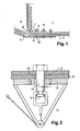
- the figure 1 shows a laminated structure 1 obtained by a stack, at least, of a panel 2 of a composite material and, here, a plate 3 of metal, for example aluminum.
- the stack may comprise several composite panels pressed together,
- the structure 1 represents a connection between a central box 4 of a fuselage of an aircraft and a wing 5.
- the panel 2 is further against wedged by a triple angle 6 aluminum.
- the bracket 6 is itself held by a single bracket 7.
- the bracket 6 and the plate 3 take the sandwich panel 2.
- These different parts are joined together by fasteners such as 8.
- the establishment of these fasteners 8 is achieved in the following manner.
- the panel 2 and the plate 3, or the panel 2, the plate 3 and the angles 6 and 7, are held together by auxiliary means. While they are maintained, their stack is pierced by a bore through which is supposed to pass the fastener 8. Then this fastener is introduced into the bore and is fixed, by screwing, bolting, or riveting.
- the fastener is introduced from the panel 2.
- the point 9 of the fastener penetrates the first into the bore through the panel 2, here by the plate 3 before the panel 2. If necessary this tip 9 has, for a sufficient length, a diameter smaller than that of the bore, allowing its free passage in the bore.
- the fastener 8 comprises in its useful parts, in line with the thickness of the stack, dimensions, a smooth round profile with a diameter, greater than the diameter of the bore. The fastener is then pulled by its tip 9 to pass completely, so that the head 10 of the fastener comes into contact with the plate 2. This is a positive interference.
- a drawing tool 11 When pulling on the fastener 8, its diameter decreases (at least slightly).
- the fastener 8 then penetrates more easily into the bore made in the parts to be joined.
- a drawing tool 11 a goat 11 in one example, figure 2 , bears against the composite panel 2, or against another metal plate which is pressed against this composite material (bracket 6 or 7 or other, when they are present).
- This other metal plate preferably in concert with the plate 3 located on the other side of the panel 2, contributes to the pinching of the panel 2 at the time of insertion of the fastener. They prevent delamination.
- the goat 11 used for the drawing comprises a rigid base 12 supported by reaction against the panel 2 at the time of fixing.
- This base 12 has a hole 13 to accommodate the head 9 of the binding.
- This hole 13 is very accurately calibrated. In one example, it is calibrated at 0.6% in addition to the diameter of the bore. Indeed, if the hole 13 is too large, at the output of the panel 2, on the edge 14 of the panel, embrittlement may occur. This phenomenon, which does not occur when the other plates or angles are present, is thus fought by adjusting the diameter of the hole 13 of the base 12. If the diameter of the hole 13 of the base 12 is too large, there is embrittlement 14. S it is too small, the attachment enters into positive interference with the base 12, and can no longer dismount the base 12 of the goat 11.
- the panel 2 does not delaminate, and generally did not deteriorate, if the positive interference (ie the negative game) n ' was not greater than 0.6%. In a preferred solution, this positive interference is the greatest possible. In one example it is 0.3%
- the value of the positive interference is essentially dependent on the difference in diameter between the bore and the attachment. However, it also results from manufacturing tolerances and elongation effects of the attachment at the time of its insertion (of its draw in fact). As a result, it has been found in the invention that from 0.6%, high losses in the mechanical strength of the fastener can be seen. In other words, it was discovered that there was a limit beyond which the positive interference was not exerted (due to delamination in particular), but above all, below which the phenomenon of positive interference could play, with all expected beneficial effects (weight gain, better resistance), and without the dreaded disadvantages (weakening at the point of fixation).
- fixation of the fastener 8 occurs either by screwing a nut or by crimping in an interference ring.
- the head 9 of the rod 8 is torn off when the draw becomes too strong, causing an automatic fixing in an interference ring.
- a rivet is mounted on the head 9.
- the preferred interference proposed by the invention lower than 0.6%, are very different from known interference when the plates to be assembled are metal plates. It was thus known to achieve interference of the order of 1% or more, given that the value of the interference intervenes directly, almost proportionately, over the lifetime of the attachment.
- the length of a fastener 8 thus mounted in positive interference was 140 mm.
- This large thickness corresponds to a stack of several panels such as 2, sandwiched or not sandwiched between metal plates such as 3.
- the laminated structure is formed from several panels of composite material, and from plates metal interposed between the panels. The percentages given here with respect to the bore are of course the same as those given with respect to the diameter of the rod of the fastener 8.
Landscapes
- Engineering & Computer Science (AREA)
- Mechanical Engineering (AREA)
- General Engineering & Computer Science (AREA)
- Aviation & Aerospace Engineering (AREA)
- Connection Of Plates (AREA)
- Laminated Bodies (AREA)
- Insertion Pins And Rivets (AREA)
Claims (10)
- Verfahren zur Erzeugung einer Laminatstruktur (1), wobei diese Laminatstruktur in einer Aufschichtung eine Paneele (2) aus Verbundmaterialien enthält, bei dem- man die Paneele in Form einer Aufschichtung anbringt,- man die Aufschichtung durchbohrt, um eine Befestigungsbohrung zu bilden,- man einen runden Befestigungsstift (8) in die Bohrung einführt, und- man die Befestigung fixiert,dadurch gekennzeichnet, dass- man beim Bohren ein negatives Spiel zwischen einem Bohrdurchmesser und einem Befestigungsdurchmesser erzeugt,- das negative Spiel 0,6% des Wertes des Bohrdurchmessers nicht übersteigen darf,- man die Befestigung von der Paneele aus einführt und man in Richtung einer Gegenpaneele zieht und- die Laminatstruktur beim Einführen der Befestigung auf der Seite, auf der die Befestigung herauskommt, durch eine Metallplatte oder durch die Gegenkraft eines Zugsockels festgehalten wird.
- Verfahren nach Anspruch 1, dadurch gekennzeichnet, dass die Befestigung von der Paneele aus eingeführt, und in Richtung einer Gegenpaneele gezogen wird.
- Verfahren nach einem der Ansprüche 1 bis 2, dadurch gekennzeichnet, dass- das negative Spiel 0,3% des Stiftdurchmesserwerts entspricht.
- Verfahren nach einem der Ansprüche 1 bis 3, dadurch gekennzeichnet, dass- die Platte aus Verbundstoff eine Platte aus Karbonfaser ist.
- Verfahren nach einem der Ansprüche 1 bis 4, dadurch gekennzeichnet, dass- man die Paneele vor dem Bohren zwischen zwei Metallplatten (3, 6) steckt.
- Verfahren nach einem der Ansprüche 1 bis 5, dadurch gekennzeichnet, dass- das Metall einer Platte Aluminium ist.
- Verfahren nach einem der Ansprüche 1 bis 6, dadurch gekennzeichnet, dass- man die Laminatstruktur aus mehreren Verbundstoffpaneelen und aus Metallplatten bildet, die zwischen de Paneele eingefügt werden.
- Verfahren nach einem der Ansprüche 1 bis 7, dadurch gekennzeichnet, dass- man zum Einführen der Befestigung über einen Zugbock (10) auf Seiten der Bohrung verfügt, die gegenüber jener liegt, durch die die Befestigung eingeführt wird,- man den Bock mit einer Gegenhalterung mit einem Zugloch ausstattet,- das Zugloch einen Durchmesser aufweist, der größer oder gleich dem Durchmesser der Befestigung ist.
- Verfahren nach einem der Ansprüche 1 bis 7, dadurch gekennzeichnet, dass- die Schichtpaneele an zumindest eine Metallplatte (3) anlegt.
- Flugzeug mit einer Laminatstruktur, die entsprechend dem Verfahren erzeugt wurde, das einem der Ansprüche 1 bis 9 entspricht.
Applications Claiming Priority (2)
| Application Number | Priority Date | Filing Date | Title |
|---|---|---|---|
| FR0350976A FR2863324B1 (fr) | 2003-12-04 | 2003-12-04 | Procede de realisation d'une structure stratifiee et avion muni d'une telle structure |
| FR0350976 | 2003-12-04 |
Publications (3)
| Publication Number | Publication Date |
|---|---|
| EP1537993A2 EP1537993A2 (de) | 2005-06-08 |
| EP1537993A3 EP1537993A3 (de) | 2006-05-10 |
| EP1537993B1 true EP1537993B1 (de) | 2008-12-31 |
Family
ID=34451771
Family Applications (1)
| Application Number | Title | Priority Date | Filing Date |
|---|---|---|---|
| EP04300814A Expired - Lifetime EP1537993B1 (de) | 2003-12-04 | 2004-11-25 | Verfahren zur Herstellung einer Schichtstruktur und mit einer solchen Struktur ausgestattetes Flugzeug |
Country Status (6)
| Country | Link |
|---|---|
| US (1) | US20050224655A1 (de) |
| EP (1) | EP1537993B1 (de) |
| AT (1) | ATE419468T1 (de) |
| CA (1) | CA2486875C (de) |
| DE (1) | DE602004018731D1 (de) |
| FR (1) | FR2863324B1 (de) |
Families Citing this family (18)
| Publication number | Priority date | Publication date | Assignee | Title |
|---|---|---|---|---|
| US20060010689A1 (en) * | 2004-07-14 | 2006-01-19 | Ali Salour | Automated drill process for two-diameter holes in multi-layer variable thickness composite materials |
| FR2883548B1 (fr) * | 2005-03-23 | 2007-06-15 | Airbus France Sas | Dispositif et procede d'eclissage mixte carbone-metal dissymetrique |
| PT2008081T (pt) * | 2006-03-16 | 2019-08-01 | Structural Monitoring Systems Ltd | Método para monitorização de fissuração num componente |
| US7546979B1 (en) | 2006-09-15 | 2009-06-16 | The Boeing Company | Trapezoidal panel pin joint allowing free deflection between fuselage and wing |
| JPWO2011105540A1 (ja) * | 2010-02-26 | 2013-06-20 | 三菱重工業株式会社 | 複合材の修理方法およびこれを用いた複合材 |
| ES2396327B1 (es) * | 2010-06-10 | 2014-02-06 | Airbus Operations, S.L. | Procedimiento para la fabricación de piezas grandes de material compuesto controlando el espesor de sus bordes |
| FR2970463B1 (fr) * | 2011-01-17 | 2013-02-15 | Airbus Operations Sas | Dispositif d'eclissage a tenue mecanique amelioree. |
| US9272769B2 (en) * | 2012-11-13 | 2016-03-01 | The Boeing Company | Joint for composite wings |
| FR3015433B1 (fr) | 2013-12-23 | 2016-02-12 | Airbus Operations Sas | Ensemble pour aeronef comprenant un mat d'accrochage integre a la nacelle et agence en partie arriere du fuselage |
| US9399507B2 (en) * | 2014-01-22 | 2016-07-26 | The Boeing Company | Joints between a composite skin and a load-bearing component and methods of forming same |
| CA2944964C (en) | 2014-04-14 | 2022-08-09 | Short Brothers Plc | Apparatus and method for forming fiber reinforced composite structures |
| US11149769B2 (en) * | 2015-04-17 | 2021-10-19 | Ford Global Technologies, Llc | Increased bottom sheet thickness on cast alloys for mechanical joining of certain materials |
| US9897132B2 (en) | 2015-06-02 | 2018-02-20 | Northrop Grumman Systems Corporation | Diffusion bonded fastener assembly |
| FR3074143A1 (fr) * | 2017-11-29 | 2019-05-31 | Airbus Operations | Nervure de jonction voilure-caisson de voilure pour aeronef et procede de fabrication d'un aeronef au moyen d'une telle nervure |
| US10773817B1 (en) | 2018-03-08 | 2020-09-15 | Northrop Grumman Systems Corporation | Bi-directional flow ram air system for an aircraft |
| JP6991085B2 (ja) * | 2018-03-22 | 2022-01-12 | 日産自動車株式会社 | Frp材へのブラケット取付構造 |
| US11305862B2 (en) * | 2019-12-20 | 2022-04-19 | The Boeing Company | Joint joining an aircraft wing to an aircraft body |
| CN111069514B (zh) * | 2019-12-31 | 2021-04-13 | 湖北三江航天红阳机电有限公司 | 一种空气舵铆接工艺方法 |
Family Cites Families (6)
| Publication number | Priority date | Publication date | Assignee | Title |
|---|---|---|---|---|
| US4012884A (en) * | 1971-09-21 | 1977-03-22 | Kaynar Mfg. Co., Inc. | Prestressed connection and fastener therefor |
| US4485510A (en) * | 1982-01-11 | 1984-12-04 | Hi-Shear Corporation | Threaded fastener having minimized length and weight and method to make it |
| DE3215152A1 (de) * | 1982-04-23 | 1983-10-27 | Hi-Shear Corp., Torrance, Calif. | Stift fuer eine auf scherung beanspruchte verbindung |
| US4850771A (en) * | 1986-04-01 | 1989-07-25 | Hurd Ramon L | Installation system for securing workpieces of composite materials and the like and threaded fastener for such system |
| DE4342968C2 (de) * | 1993-12-16 | 2000-08-31 | Hydro Control Steuerungstechni | Nietsetzgerät mit Setzkopfzentrierung |
| US6325582B1 (en) * | 2000-07-06 | 2001-12-04 | Huck International, Inc. | Swage type fastener with low swage load |
-
2003
- 2003-12-04 FR FR0350976A patent/FR2863324B1/fr not_active Expired - Fee Related
-
2004
- 2004-11-25 EP EP04300814A patent/EP1537993B1/de not_active Expired - Lifetime
- 2004-11-25 DE DE602004018731T patent/DE602004018731D1/de not_active Expired - Lifetime
- 2004-11-25 AT AT04300814T patent/ATE419468T1/de not_active IP Right Cessation
- 2004-11-30 CA CA2486875A patent/CA2486875C/fr not_active Expired - Fee Related
- 2004-12-01 US US11/001,682 patent/US20050224655A1/en not_active Abandoned
Also Published As
| Publication number | Publication date |
|---|---|
| US20050224655A1 (en) | 2005-10-13 |
| FR2863324A1 (fr) | 2005-06-10 |
| EP1537993A3 (de) | 2006-05-10 |
| ATE419468T1 (de) | 2009-01-15 |
| CA2486875C (fr) | 2013-12-24 |
| DE602004018731D1 (de) | 2009-02-12 |
| FR2863324B1 (fr) | 2007-12-14 |
| CA2486875A1 (fr) | 2005-06-04 |
| EP1537993A2 (de) | 2005-06-08 |
Similar Documents
| Publication | Publication Date | Title |
|---|---|---|
| CA2486875C (fr) | Procede de realisation d'une structure stratifiee et avion muni d'une telle structure | |
| EP0398403B1 (de) | Blindnietelement, Montageverfahren und dadurch entstehende Bauteile | |
| EP3308040B1 (de) | An einer einzigen seite angebrachtes anbauteil | |
| EP1342927B1 (de) | Vorrichtung zum Befestigen eines Bauteils an einer Luftfahrzeugstruktur | |
| EP1234984A2 (de) | Vorrichtung zum Verbinden einer Kompositplatte mit einer Trägerkonstruktion | |
| EP2271850B1 (de) | Verfahren zur montage eines teils aus metallmaterial an einem teil aus verbundmaterial | |
| FR2551147A1 (fr) | Procede et dispositif pour reduire les forces et les couts de montage dans un systeme a boulon conique | |
| FR2984274A1 (fr) | Poutre securisee, en particulier cadre fort de fuselage, ainsi que fuselage d'aeronef equipe de tels cadres | |
| FR2931911A1 (fr) | Systeme et procede d'assemblage par brides entre deux pieces tournantes | |
| EP3366932A1 (de) | Einsatz zum crimpen, befestigungselement und -einheit, die einen solchen einsatz umfassen, und herstellungsverfahren von solchen teilen | |
| WO2019073076A1 (fr) | Ecrou rainuré pour fixation aveugle, rivet et assemblage comportant un tel écrou | |
| WO2008148993A2 (fr) | Procede d'assemblage entre une piece en materiau metallique et une piece en materiau composite au moyen d'une fixation | |
| EP2344775B1 (de) | Blindbefestigungsvorrichtung | |
| EP1941167B1 (de) | Blindniet und verfahren zu dessen entfernung | |
| FR3019864A1 (fr) | Assemblage rivete et procede de fabrication associe | |
| WO2007026089A1 (fr) | Rivet aveugle notamment pour fixation de structure et son procede de pose | |
| FR3017429A1 (fr) | Ecrou a sertir en aveugle sur un support | |
| FR3117049A1 (fr) | Procédé de pose d’une fixation au travers d’un assemblage de pièces structurales avec fluage d’un mastic interposé | |
| FR2964365A1 (fr) | Procede pour fixer entre elles des pieces d'aeronef | |
| EP4174330B1 (de) | Verfahren und befestigung zum zusammenbau mindestens zweier elementarer bauteile | |
| EP3037684B1 (de) | Abdeckung mit vertiefungen und/oder relief | |
| WO2021052981A1 (fr) | Fixation aveugle avec freinage chimique et procédé d'installation associé | |
| EP3724523B1 (de) | Befestigungsvorrichtung, befestigungsanordnung mit einer solchen vorrichtung und verfahren zur herstellung einer solchen anordnung | |
| EP4688403A1 (de) | Anordnung mit mindestens einem verbundteil und befestigungsmitteln | |
| FR3127425A1 (fr) | Assemblage destiné à une turbomachine pour aéronef |
Legal Events
| Date | Code | Title | Description |
|---|---|---|---|
| PUAI | Public reference made under article 153(3) epc to a published international application that has entered the european phase |
Free format text: ORIGINAL CODE: 0009012 |
|
| AK | Designated contracting states |
Kind code of ref document: A2 Designated state(s): AT BE BG CH CY CZ DE DK EE ES FI FR GB GR HU IE IS IT LI LU MC NL PL PT RO SE SI SK TR |
|
| AX | Request for extension of the european patent |
Extension state: AL HR LT LV MK YU |
|
| PUAL | Search report despatched |
Free format text: ORIGINAL CODE: 0009013 |
|
| AK | Designated contracting states |
Kind code of ref document: A3 Designated state(s): AT BE BG CH CY CZ DE DK EE ES FI FR GB GR HU IE IS IT LI LU MC NL PL PT RO SE SI SK TR |
|
| AX | Request for extension of the european patent |
Extension state: AL HR LT LV MK YU |
|
| RIC1 | Information provided on ipc code assigned before grant |
Ipc: F16B 4/00 20060101ALI20060321BHEP Ipc: F16B 5/04 20060101AFI20060321BHEP Ipc: B64C 1/00 20060101ALI20060321BHEP |
|
| RIC1 | Information provided on ipc code assigned before grant |
Ipc: F16B 5/04 20060101AFI20060327BHEP Ipc: B64C 1/00 20060101ALI20060327BHEP Ipc: B32B 37/00 20060101ALI20060327BHEP Ipc: F16B 4/00 20060101ALI20060327BHEP |
|
| 17P | Request for examination filed |
Effective date: 20061031 |
|
| AKX | Designation fees paid |
Designated state(s): AT BE BG CH CY CZ DE DK EE ES FI FR GB GR HU IE IS IT LI LU MC NL PL PT RO SE SI SK TR |
|
| 17Q | First examination report despatched |
Effective date: 20070302 |
|
| REG | Reference to a national code |
Ref country code: SE Ref legal event code: TRGR |
|
| GRAP | Despatch of communication of intention to grant a patent |
Free format text: ORIGINAL CODE: EPIDOSNIGR1 |
|
| GRAS | Grant fee paid |
Free format text: ORIGINAL CODE: EPIDOSNIGR3 |
|
| GRAA | (expected) grant |
Free format text: ORIGINAL CODE: 0009210 |
|
| AK | Designated contracting states |
Kind code of ref document: B1 Designated state(s): AT BE BG CH CY CZ DE DK EE ES FI FR GB GR HU IE IS IT LI LU MC NL PL PT RO SE SI SK TR |
|
| REG | Reference to a national code |
Ref country code: GB Ref legal event code: FG4D Free format text: NOT ENGLISH Ref country code: CH Ref legal event code: EP |
|
| REF | Corresponds to: |
Ref document number: 602004018731 Country of ref document: DE Date of ref document: 20090212 Kind code of ref document: P |
|
| REG | Reference to a national code |
Ref country code: IE Ref legal event code: FG4D Free format text: LANGUAGE OF EP DOCUMENT: FRENCH |
|
| PG25 | Lapsed in a contracting state [announced via postgrant information from national office to epo] |
Ref country code: PL Free format text: LAPSE BECAUSE OF FAILURE TO SUBMIT A TRANSLATION OF THE DESCRIPTION OR TO PAY THE FEE WITHIN THE PRESCRIBED TIME-LIMIT Effective date: 20081231 Ref country code: NL Free format text: LAPSE BECAUSE OF FAILURE TO SUBMIT A TRANSLATION OF THE DESCRIPTION OR TO PAY THE FEE WITHIN THE PRESCRIBED TIME-LIMIT Effective date: 20081231 Ref country code: SI Free format text: LAPSE BECAUSE OF FAILURE TO SUBMIT A TRANSLATION OF THE DESCRIPTION OR TO PAY THE FEE WITHIN THE PRESCRIBED TIME-LIMIT Effective date: 20081231 Ref country code: FI Free format text: LAPSE BECAUSE OF FAILURE TO SUBMIT A TRANSLATION OF THE DESCRIPTION OR TO PAY THE FEE WITHIN THE PRESCRIBED TIME-LIMIT Effective date: 20081231 |
|
| NLV1 | Nl: lapsed or annulled due to failure to fulfill the requirements of art. 29p and 29m of the patents act | ||
| PG25 | Lapsed in a contracting state [announced via postgrant information from national office to epo] |
Ref country code: RO Free format text: LAPSE BECAUSE OF FAILURE TO SUBMIT A TRANSLATION OF THE DESCRIPTION OR TO PAY THE FEE WITHIN THE PRESCRIBED TIME-LIMIT Effective date: 20081231 Ref country code: ES Free format text: LAPSE BECAUSE OF FAILURE TO SUBMIT A TRANSLATION OF THE DESCRIPTION OR TO PAY THE FEE WITHIN THE PRESCRIBED TIME-LIMIT Effective date: 20090411 Ref country code: EE Free format text: LAPSE BECAUSE OF FAILURE TO SUBMIT A TRANSLATION OF THE DESCRIPTION OR TO PAY THE FEE WITHIN THE PRESCRIBED TIME-LIMIT Effective date: 20081231 |
|
| REG | Reference to a national code |
Ref country code: IE Ref legal event code: FD4D |
|
| PG25 | Lapsed in a contracting state [announced via postgrant information from national office to epo] |
Ref country code: PT Free format text: LAPSE BECAUSE OF FAILURE TO SUBMIT A TRANSLATION OF THE DESCRIPTION OR TO PAY THE FEE WITHIN THE PRESCRIBED TIME-LIMIT Effective date: 20090601 Ref country code: AT Free format text: LAPSE BECAUSE OF FAILURE TO SUBMIT A TRANSLATION OF THE DESCRIPTION OR TO PAY THE FEE WITHIN THE PRESCRIBED TIME-LIMIT Effective date: 20081231 Ref country code: IS Free format text: LAPSE BECAUSE OF FAILURE TO SUBMIT A TRANSLATION OF THE DESCRIPTION OR TO PAY THE FEE WITHIN THE PRESCRIBED TIME-LIMIT Effective date: 20090430 Ref country code: CZ Free format text: LAPSE BECAUSE OF FAILURE TO SUBMIT A TRANSLATION OF THE DESCRIPTION OR TO PAY THE FEE WITHIN THE PRESCRIBED TIME-LIMIT Effective date: 20081231 |
|
| PG25 | Lapsed in a contracting state [announced via postgrant information from national office to epo] |
Ref country code: SK Free format text: LAPSE BECAUSE OF FAILURE TO SUBMIT A TRANSLATION OF THE DESCRIPTION OR TO PAY THE FEE WITHIN THE PRESCRIBED TIME-LIMIT Effective date: 20081231 |
|
| PG25 | Lapsed in a contracting state [announced via postgrant information from national office to epo] |
Ref country code: IE Free format text: LAPSE BECAUSE OF FAILURE TO SUBMIT A TRANSLATION OF THE DESCRIPTION OR TO PAY THE FEE WITHIN THE PRESCRIBED TIME-LIMIT Effective date: 20081231 Ref country code: DK Free format text: LAPSE BECAUSE OF FAILURE TO SUBMIT A TRANSLATION OF THE DESCRIPTION OR TO PAY THE FEE WITHIN THE PRESCRIBED TIME-LIMIT Effective date: 20081231 |
|
| PLBE | No opposition filed within time limit |
Free format text: ORIGINAL CODE: 0009261 |
|
| STAA | Information on the status of an ep patent application or granted ep patent |
Free format text: STATUS: NO OPPOSITION FILED WITHIN TIME LIMIT |
|
| 26N | No opposition filed |
Effective date: 20091001 |
|
| PG25 | Lapsed in a contracting state [announced via postgrant information from national office to epo] |
Ref country code: BG Free format text: LAPSE BECAUSE OF FAILURE TO SUBMIT A TRANSLATION OF THE DESCRIPTION OR TO PAY THE FEE WITHIN THE PRESCRIBED TIME-LIMIT Effective date: 20090331 |
|
| BERE | Be: lapsed |
Owner name: AIRBUS FRANCE Effective date: 20091130 |
|
| PG25 | Lapsed in a contracting state [announced via postgrant information from national office to epo] |
Ref country code: MC Free format text: LAPSE BECAUSE OF NON-PAYMENT OF DUE FEES Effective date: 20091130 |
|
| REG | Reference to a national code |
Ref country code: CH Ref legal event code: PL |
|
| PG25 | Lapsed in a contracting state [announced via postgrant information from national office to epo] |
Ref country code: GR Free format text: LAPSE BECAUSE OF FAILURE TO SUBMIT A TRANSLATION OF THE DESCRIPTION OR TO PAY THE FEE WITHIN THE PRESCRIBED TIME-LIMIT Effective date: 20090401 Ref country code: BE Free format text: LAPSE BECAUSE OF NON-PAYMENT OF DUE FEES Effective date: 20091130 Ref country code: LI Free format text: LAPSE BECAUSE OF NON-PAYMENT OF DUE FEES Effective date: 20091130 Ref country code: CH Free format text: LAPSE BECAUSE OF NON-PAYMENT OF DUE FEES Effective date: 20091130 |
|
| PG25 | Lapsed in a contracting state [announced via postgrant information from national office to epo] |
Ref country code: LU Free format text: LAPSE BECAUSE OF NON-PAYMENT OF DUE FEES Effective date: 20091125 |
|
| PG25 | Lapsed in a contracting state [announced via postgrant information from national office to epo] |
Ref country code: HU Free format text: LAPSE BECAUSE OF FAILURE TO SUBMIT A TRANSLATION OF THE DESCRIPTION OR TO PAY THE FEE WITHIN THE PRESCRIBED TIME-LIMIT Effective date: 20090701 |
|
| REG | Reference to a national code |
Ref country code: GB Ref legal event code: 732E Free format text: REGISTERED BETWEEN 20110721 AND 20110727 |
|
| PG25 | Lapsed in a contracting state [announced via postgrant information from national office to epo] |
Ref country code: TR Free format text: LAPSE BECAUSE OF FAILURE TO SUBMIT A TRANSLATION OF THE DESCRIPTION OR TO PAY THE FEE WITHIN THE PRESCRIBED TIME-LIMIT Effective date: 20081231 |
|
| PG25 | Lapsed in a contracting state [announced via postgrant information from national office to epo] |
Ref country code: CY Free format text: LAPSE BECAUSE OF FAILURE TO SUBMIT A TRANSLATION OF THE DESCRIPTION OR TO PAY THE FEE WITHIN THE PRESCRIBED TIME-LIMIT Effective date: 20081231 |
|
| REG | Reference to a national code |
Ref country code: FR Ref legal event code: TP Owner name: AIRBUS HOLDING, FR Effective date: 20110913 Ref country code: FR Ref legal event code: CD Owner name: AIRBUS HOLDING, FR Effective date: 20110916 Ref country code: FR Ref legal event code: CA Effective date: 20110916 Ref country code: FR Ref legal event code: CJ Effective date: 20110916 |
|
| REG | Reference to a national code |
Ref country code: DE Ref legal event code: R082 Ref document number: 602004018731 Country of ref document: DE Representative=s name: PETER MAHLER, DE |
|
| REG | Reference to a national code |
Ref country code: DE Ref legal event code: R081 Ref document number: 602004018731 Country of ref document: DE Owner name: AIRBUS OPERATIONS SAS, FR Free format text: FORMER OWNER: AIRBUS FRANCE, TOULOUSE, FR Effective date: 20120326 Ref country code: DE Ref legal event code: R082 Ref document number: 602004018731 Country of ref document: DE Representative=s name: MAHLER, PETER, DIPL.-PHYS., DE Effective date: 20120326 |
|
| PGFP | Annual fee paid to national office [announced via postgrant information from national office to epo] |
Ref country code: SE Payment date: 20121120 Year of fee payment: 9 |
|
| REG | Reference to a national code |
Ref country code: SE Ref legal event code: EUG |
|
| PG25 | Lapsed in a contracting state [announced via postgrant information from national office to epo] |
Ref country code: SE Free format text: LAPSE BECAUSE OF NON-PAYMENT OF DUE FEES Effective date: 20131126 |
|
| REG | Reference to a national code |
Ref country code: FR Ref legal event code: PLFP Year of fee payment: 12 |
|
| REG | Reference to a national code |
Ref country code: FR Ref legal event code: PLFP Year of fee payment: 13 |
|
| REG | Reference to a national code |
Ref country code: FR Ref legal event code: PLFP Year of fee payment: 14 |
|
| PGFP | Annual fee paid to national office [announced via postgrant information from national office to epo] |
Ref country code: DE Payment date: 20191121 Year of fee payment: 16 |
|
| PGFP | Annual fee paid to national office [announced via postgrant information from national office to epo] |
Ref country code: FR Payment date: 20191120 Year of fee payment: 16 Ref country code: IT Payment date: 20191128 Year of fee payment: 16 |
|
| PGFP | Annual fee paid to national office [announced via postgrant information from national office to epo] |
Ref country code: GB Payment date: 20191120 Year of fee payment: 16 |
|
| REG | Reference to a national code |
Ref country code: DE Ref legal event code: R119 Ref document number: 602004018731 Country of ref document: DE |
|
| GBPC | Gb: european patent ceased through non-payment of renewal fee |
Effective date: 20201125 |
|
| PG25 | Lapsed in a contracting state [announced via postgrant information from national office to epo] |
Ref country code: FR Free format text: LAPSE BECAUSE OF NON-PAYMENT OF DUE FEES Effective date: 20201130 Ref country code: IT Free format text: LAPSE BECAUSE OF NON-PAYMENT OF DUE FEES Effective date: 20201125 |
|
| PG25 | Lapsed in a contracting state [announced via postgrant information from national office to epo] |
Ref country code: GB Free format text: LAPSE BECAUSE OF NON-PAYMENT OF DUE FEES Effective date: 20201125 Ref country code: DE Free format text: LAPSE BECAUSE OF NON-PAYMENT OF DUE FEES Effective date: 20210601 |