EP1537844A1 - Biomechanical stimulation device - Google Patents
Biomechanical stimulation device Download PDFInfo
- Publication number
- EP1537844A1 EP1537844A1 EP03028004A EP03028004A EP1537844A1 EP 1537844 A1 EP1537844 A1 EP 1537844A1 EP 03028004 A EP03028004 A EP 03028004A EP 03028004 A EP03028004 A EP 03028004A EP 1537844 A1 EP1537844 A1 EP 1537844A1
- Authority
- EP
- European Patent Office
- Prior art keywords
- platform
- base
- base plate
- circular
- bms
- Prior art date
- Legal status (The legal status is an assumption and is not a legal conclusion. Google has not performed a legal analysis and makes no representation as to the accuracy of the status listed.)
- Granted
Links
Images

Classifications
-
- A—HUMAN NECESSITIES
- A61—MEDICAL OR VETERINARY SCIENCE; HYGIENE
- A61H—PHYSICAL THERAPY APPARATUS, e.g. DEVICES FOR LOCATING OR STIMULATING REFLEX POINTS IN THE BODY; ARTIFICIAL RESPIRATION; MASSAGE; BATHING DEVICES FOR SPECIAL THERAPEUTIC OR HYGIENIC PURPOSES OR SPECIFIC PARTS OF THE BODY
- A61H1/00—Apparatus for passive exercising; Vibrating apparatus ; Chiropractic devices, e.g. body impacting devices, external devices for briefly extending or aligning unbroken bones
- A61H1/005—Moveable platform, e.g. vibrating or oscillating platform for standing, sitting, laying, leaning
Definitions
- the present invention relates to an improved biomechanical device Stimulation of muscles.
- Biomechanical Muscle Stimulation was developed in Russia in the late 1970s developed by Prof. Nazarov and there primarily in the field of competitive sports used.
- the BMS is based on an exclusively mechanical action on the human body with oscillations in each case a certain frequency and a certain amplitude, according to the desired application to be selected.
- the vibrations that resemble the natural of the body and These mimic, act on strained or stretched muscles along the muscle fiber one.
- By deliberately influencing the body's own vibration parameters thus by the BMS positive effects, for example on the circulation and Lymphatic system generated.
- the BMS in the cosmetic field, for example, against wrinkling or cellulite.
- the BMS is transformed into more or less by means of randomly generated vibrations less linear (vertical) direction performed. It comes to a hub that is adversely affects the user.
- the devices are designed in such a way that only a limited number of body parts, for example only the leg or arm area - BMS can be subjected.
- the BMS advantageously Perform when stimulation by a uniform circular or elliptical motion is generated.
- the device according to the invention thereby not only a force vertical to Platform exercised, but also a substantially parallel to the platform acting Traction. This leads to a significantly improved biomechanical stimulation of the on the platform located body part.
- a device comprising a base plate, a socket connected to the base plate and a via a Drive device connected to the pedestal, characterized in that that the platform during operation a circular or elliptical movement around an axis, which lies outside the center of gravity of the platform, exercises and hereby experiences a parallel shift.
- the inventive device comprises a base plate for stable installation of the device on a flat surface.
- preference may be given to Base plate additional weights are arranged to the stability especially when operating at high frequencies by fixing the base plate too increase.
- a base Connected to the base plate, a base is arranged.
- the base preferably has an L-shape whose shorter end is fixedly connected to the base plate, and whose longer end extends vertically to the base plate in the height.
- an L-shape is also understood to mean a shape in which the two sections do not include a right angle or the larger section is curved.
- Socket facilities provided for operating the device.
- Especially preferred is over substantially the entire length of the longer section of the L-shaped Pedestal towards the base plate and platform a band with electrical connection provided for the drive device. By repeatedly pressing this band can the operator starts or stops the device according to the invention.
- Farther preferably two handles are arranged at the upper end of the base. A user can hold on to these handles. Of course they are Other common brackets conceivable.
- the inventive device is for better transport with at least one wheel fitted.
- a platform which has a Drive device is movably connected to the base.
- a Drive device is movably connected to the base.
- the shorter piece of the L-shaped socket on a portion of the base plate.
- the drive device is connected.
- the platform is over bearings with the drive device such connected to set in the desired circular or elliptical movement can be.
- a cover arranged so that the drive device is not accessible from the outside.
- the platform is ergonomic Form has. Under an ergonomic shape according to the present Invention understood a form that does not include corners or edges. To this Way, the platform can be used from all directions without this for The user would be uncomfortable or even at risk of injury. According to the invention, the platform is preferably oval.
- the platform has a ergonomic shape and has a lower surface area than the surface the surface of the base plate.
- the user can access the Base plate, indicating the stability of the device during operation improved, and the device by placing a body part, such as a leg or Arms, to use the platform.
- Due to the ergonomic shape is the platform accessible from every direction.
- the invention is preferably the Area of the surface of the platform 30-70% of the surface area of the surface the base plate.
- Upper and lower limits result from the fact that the platform on the one hand must have a certain surface area for use, and on the other hand, if the area of the platform is too large, the advantages described here can not be realized because the user then does not during the operation can put more on the base plate.
- the device according to the invention can thus a variety of exercises be performed.
- the devices allow the state of the Technique just carrying out a limited number of exercises.
- the Uses of the inventive device are characterized by the special Design of the device considerably expanded.
- the device according to the invention are in the Platform openings provided.
- ropes can pass through these openings or tapes and connected to the platform.
- further exercises can be performed.
- the user may be on the device Base plate and pull the ropes or bands or a Lead the body part and use the device in this way.
- the platform undergoes a uniform circular or elliptical movement.
- the inventive device which perform a random movement is the inventive device the Movement forced and absolutely uniform. It has been shown that on this Way the biomechanical muscle stimulation can be performed much more effectively can as if the BMS by random and therefore non-uniform movements he follows.
- the device according to the invention thereby exerted not only a force vertical to the platform, but also a tensile force acting essentially parallel to the platform. this leads to to a significantly improved biomechanical stimulation of the platform located body part.
- a circular movement is preferred.
- the present invention will move under a circular motion understood that deviates no more than 5% from an ideal circular motion.
- the axis around which the platform moves in a circle can be arbitrary in space be arranged. According to the invention, this axis is preferably parallel to the axis Base plate below the platform and in particular preferably perpendicular to a Axis perpendicular through the pedestal.
- the movement of the platform preferably takes place at a frequency from 5 to 35 Hz.
- the circular or elliptical movement of the platform can through common and the Expert known drive devices are generated.
- the movement is generated by an eccentric drive.
- the eccentric drive is the skilled person well known and therefore need not be explained here become.
- an eccentric shaft is conventional Components such as rods, rollers, bearings, belts or gears with the platform connected
- the movement performed by the platform is shown in FIG. 1 for the example of FIG shown circular motion.
- the platform P moves around the axis A. So during this rotation, there is no tilting of the platform P. This experiences a parallel shift.
- the platform P i.e., the platform in the Home position
- the platform P ' i.e., the platform after rotation through 90 °
- the platform P "(i.e. the platform after rotation through 180 °) and the platform P '' '(i.e., the platform after a 270 ° rotation) are thus each parallel to each other.
- the stroke of the platform during the movement is according to the present invention preferably not more than 4 mm.
- the device according to the invention can be used in the fitness, cosmetics and health sector be used.
- the fitness area is the muscle and the increase of Endurance performance of the user in the foreground.
- the device can For example, be used against cellulite or wrinkling.
- Indications Connective tissue weakness, Degenerative rheumatic diseases, migraine, muscle tension or weakness, Pain in the musculoskeletal system, build up of muscles Muscle atrophy, degenerative processes on intervertebral discs (arthrosis), fractures, Joint diseases (for example, tennis elbow), joint instability, myelosis, shoulder-back, Hip, knee and ankle problems, circulatory disorders, Congestion syndrome (ulcus cruris), edema absorption, neuropathies, Metabolic, urinary incontinence, multiple sclerosis, muscular dystrophy, Parkinson's syndrome, stroke, arthrogenic (venous) congestive syndrome (ulcus cruris), circulatory disorders, Ehlers-Danlos syndrome, scleroderma, periodontal disease, Musculoskeletal discomfort, blood flow improvement of the optic nerve, strengthening the Eye ring musculature, facial paralysis, forehead Maxillary sinus symptoms, Chronic Rhinitis, tinnitus aurium and
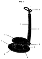
- an L-shaped base 2 On a part of an oval base plate 1, an L-shaped base 2 is attached, whose shorter portion is surrounded by a cover 7.
- the driving device for the Platform 3 arranged.
- this is a Excenterwelle, which causes the circular motion of the platform 3.
- a Operating unit 8 At the end of the shorter portion of the L-shaped base 2 is additionally a Operating unit 8 for adjusting the device according to the invention.
- two wheels 6 are mounted to facilitate easy transport of the To ensure device according to the invention.
- a handle 4 At the top of the longer one Section of the L-shaped base 2 is a handle 4, at which the User can hold during operation of the inventive device.
- a band 5 is attached.
- the band 5 is electrically connected to the drive device in the base 2.
- the Platform 3 is in the socket 2 (in its part surrounded by the cover 7) located movable drive device, so that the platform 3 through the Drive device can be moved circular or elliptical.
- the surface of the platform 3 has a smaller surface area than the surface Surface of the base plate 1 on. The user can thus during the operation also on the base plate 1 and only certain body parts on the platform. 3 bring and target this to the BMS.
- On the platform 3 are still openings 9. Through these openings can be ropes or bands for additional exercises are performed.
Abstract
Description
Die vorliegende Erfindung betrifft ein verbessertes Gerät zur biomechanischen Stimulation von Muskeln.The present invention relates to an improved biomechanical device Stimulation of muscles.
Die Biomechanische Muskelstimulation (BMS) wurde Ende der 70er Jahre in Russland von Prof. Nazarov entwickelt und dort in erster Linie im Bereich des Leistungssports eingesetzt. Die BMS beruht auf einer ausschließlich mechanischen Einwirkung auf den menschlichen Körper mit Schwingungen in jeweils einer bestimmten Frequenz und einer bestimmten Amplitude, die entsprechend der gewünschten Anwendung ausgewählt werden. Die Schwingungen, die den natürlichen des Körpers ähneln und diese imitieren, wirken auf angespannte oder gedehnte Muskeln längs zur Muskelfaser ein. Durch gezielte Beeinflussung der körpereigenen Schwingungsparameter werden somit durch die BMS positive Effekte beispielsweise auf das Kreislauf- und Lymphsystem erzeugt.Biomechanical Muscle Stimulation (BMS) was developed in Russia in the late 1970s developed by Prof. Nazarov and there primarily in the field of competitive sports used. The BMS is based on an exclusively mechanical action on the human body with oscillations in each case a certain frequency and a certain amplitude, according to the desired application to be selected. The vibrations that resemble the natural of the body and These mimic, act on strained or stretched muscles along the muscle fiber one. By deliberately influencing the body's own vibration parameters thus by the BMS positive effects, for example on the circulation and Lymphatic system generated.
So kommt es aufgrund einer durch BMS hervorgerufenen Steigerung der Muskelbewegungen zu einer deutlich erhöhten Durchblutung des Muskels beziehungsweise des entsprechenden Körperteils. Dies kann zur Behandlung von Krankheiten wie peripheren Durchblutungsstörungen ausgenützt werden.This is the result of a BMS - induced increase in Muscle movements lead to a significantly increased circulation of the muscle or the corresponding body part. This can be used to treat Diseases such as peripheral circulatory disorders are exploited.
Andererseits kann mit Hilfe der BMS aber auch gezielt Muskelaufbau betrieben werden, was im sportlichen Bereich, aber auch im Gesundheitsbereich - beispielsweise beim Muskelaufbau im Rahmen von Rehabitilationsmaßnahmen - Anwendung findet.On the other hand, with the help of BMS but also targeted muscle building can be operated, what in the field of sport, but also in the health sector - for example Muscle building in the context of rehabilitation measures - application finds.
Zudem kann die BMS im kosmetischen Bereich beispielsweise gegen Faltenbildung oder Cellulite eingesetzt werden.In addition, the BMS in the cosmetic field, for example, against wrinkling or cellulite.
Im Stand der Technik sind bereits Geräte zur Durchführung der BMS beschrieben, beispielsweise in der DE-A-199 44 456, der DE-U-201 16 277 oder der DE-U-202 19 435. Hierbei wird die BMS mit Hilfe von zufällig erzeugten Vibrationen in mehr oder weniger linearer (vertikaler) Richtung durchgeführt. Es kommt zu einem Hub, der sich nachteilig auf den Benutzer auswirkt. Zudem sind die Geräte derart konzipiert, dass nur eine limitierte Anzahl an Körperpartien, beispielsweise nur der Bein- oder Armbereich - der BMS unterzogen werden kann.Devices for carrying out the BMS are already described in the prior art, for example in DE-A-199 44 456, DE-U-201 16 277 or DE-U-202 19 435. Here, the BMS is transformed into more or less by means of randomly generated vibrations less linear (vertical) direction performed. It comes to a hub that is adversely affects the user. In addition, the devices are designed in such a way that only a limited number of body parts, for example only the leg or arm area - BMS can be subjected.
Es war die Aufgabe der vorliegenden Erfindung, ein Gerät zur verbesserten biomechanischen Stimulation bereitzustellen.It was the object of the present invention to provide a device for improved to provide biomechanical stimulation.
Diese Aufgabe wird durch ein Gerät gemäss Anspruch 1 gelöst.This object is achieved by a device according to
Es wurde überraschend gefunden, dass sich die BMS auf vorteilhafte Weise durchführen lässt, wenn die Stimulation durch eine gleichförmige kreisförmige oder elliptische Bewegung erzeugt wird. Im Gegensatz zu den Geräten aus dem Stand der Technik wird beim erfindungsgemässen Gerät dadurch nicht nur eine Kraft vertikal zur Plattform ausgeübt, sondern auch eine im wesentlichen parallel zur Plattform wirkende Zugkraft. Dies führt zu einer erheblich verbesserten biomechanischen Stimulation des auf der Plattform befindlichen Körperteils.It has surprisingly been found that the BMS advantageously Perform when stimulation by a uniform circular or elliptical motion is generated. In contrast to the devices from the state of the Technology is the device according to the invention thereby not only a force vertical to Platform exercised, but also a substantially parallel to the platform acting Traction. This leads to a significantly improved biomechanical stimulation of the on the platform located body part.
Gemäss der vorliegenden Erfindung wird deshalb ein Gerät bereitgestellt, umfassend eine Grundplatte, einen mit der Grundplatte verbundenen Sockel sowie eine über eine Antriebsvorrichtung mit dem Sockel verbundene Plattform, dadurch gekennzeichnet, dass die Plattform während des Betriebs eine kreisförmige oder elliptische Bewegung um eine Achse, welche ausserhalb des Schwerpunkts der Plattform liegt, ausübt und hierbei eine Parallelverschiebung erfährt.Therefore, according to the present invention, there is provided a device comprising a base plate, a socket connected to the base plate and a via a Drive device connected to the pedestal, characterized in that that the platform during operation a circular or elliptical movement around an axis, which lies outside the center of gravity of the platform, exercises and hereby experiences a parallel shift.
Das erfindungsgemässe Gerät umfasst eine Grundplatte zur standfesten Aufstellung des Geräts auf einer ebenen Fläche. Erfindungsgemäss bevorzugt können auf die Grundplatte zusätzliche Gewichte angeordnet werden, um die Standfestigkeit insbesondere beim Betrieb mit hohen Frequenzen durch Fixierung der Grundplatte zu erhöhen.The inventive device comprises a base plate for stable installation of the device on a flat surface. According to the invention, preference may be given to Base plate additional weights are arranged to the stability especially when operating at high frequencies by fixing the base plate too increase.
Mit der Grundplatte verbunden ist ein Sockel angeordnet. Der Sockel hat vorzugsweise eine L-Form, dessen kürzeres Ende fest mit der Grundplatte verbunden ist, und dessen längeres Ende sich vertikal zur Grundplatte in die Höhe erstreckt. Erfindungsgemäss wird dabei unter L-Form auch eine Form verstanden, bei welcher die beiden Abschnitte keinen rechten Winkel einschliessen beziehungsweise der grössere Abschnitt gekrümmt ist. An diesem Sockel kann sich ein Benutzer während des Betriebs des erfindungsgemässen Geräts festhalten. Erfindungsgemäss bevorzugt sind an dem Sockel Einrichtungen zur Bedienung des Geräts vorgesehen. Insbesondere bevorzugt ist über im wesentlichen die gesamte Länge des längeren Abschnitts des L-förmigen Sockels in Richtung zur Grundplatte und Plattform ein Band mit elektrischer Verbindung zur Antriebsvorrichtung vorgesehen. Durch wiederholtes Drücken dieses Bandes kann der Bediener das erfindungsgemäss Gerät in Betrieb setzen oder anhalten. Weiterhin erfindungsgemäss bevorzugt sind am oberen Ende des Sockels zwei Griffe angeordnet. An diesen Griffen kann sich ein Benutzer festhalten. Es sind selbstverständlich aber auch andere gängige Halterungen denkbar.Connected to the base plate, a base is arranged. The base preferably has an L-shape whose shorter end is fixedly connected to the base plate, and whose longer end extends vertically to the base plate in the height. According to the invention In this case, an L-shape is also understood to mean a shape in which the two sections do not include a right angle or the larger section is curved. At this base, a user can during the operation of the Hold the device according to the invention. According to the invention, preference is given to Socket facilities provided for operating the device. Especially preferred is over substantially the entire length of the longer section of the L-shaped Pedestal towards the base plate and platform a band with electrical connection provided for the drive device. By repeatedly pressing this band can the operator starts or stops the device according to the invention. Farther According to the invention preferably two handles are arranged at the upper end of the base. A user can hold on to these handles. Of course they are Other common brackets conceivable.
Das erfindungsgemässe Gerät ist zum besseren Transport mit mindestens einem Rad ausgestattet. Vorzugsweise befinden sich in der Nähe der Verbindung von Sockel und Grundplatte zwei Räder, welche insbesondere seitlich des Sockels an dessen unterem Ende angeordnet sind.The inventive device is for better transport with at least one wheel fitted. Preferably located in the vicinity of the connection of socket and Base plate two wheels, which in particular laterally of the base to the lower Are arranged at the end.
Beim erfindungsgemässen Gerät ist eine Plattform bereitgestellt, welche über eine Antriebsvorrichtung beweglich mit dem Sockel verbunden ist. Vorzugsweise befindet sich das kürzere Stück des L-förmigen Sockels auf einem Abschnitt der Grundplatte. Mit diesem Teil des Sockels ist die Antriebsvorrichtung verbunden. Vorzugsweise befindet sich in diesem Teil des Sockels eine Öffnung, durch welche sich die Antriebsvorrichtung erstreckt. Die Plattform ist über Lagerungen mit der Antriebsvorrichtung derart verbunden, dass sie in die gewünschte kreisförmige oder elliptische Bewegung versetzt werden kann.In the device according to the invention, a platform is provided, which has a Drive device is movably connected to the base. Preferably located the shorter piece of the L-shaped socket on a portion of the base plate. With this part of the base, the drive device is connected. Preferably located in this part of the base an opening through which the drive device extends. The platform is over bearings with the drive device such connected to set in the desired circular or elliptical movement can be.
Vorzugsweise ist auf dem Abschnitt der Grundplatte, auf welchem der Sockel angeordnet ist und über welchen sich die Plattform befindet, eine Abdeckung angeordnet, so dass die Antriebsvorrichtung von aussen nicht zugänglich ist.Preferably, on the portion of the base plate on which the pedestal is arranged and over which the platform is located, a cover arranged so that the drive device is not accessible from the outside.
Es ist erfindungsgemäss besonders bevorzugt, dass die Plattform eine ergonomische Form aufweist. Unter einer ergonomischen Form wird gemäss der vorliegenden Erfindung eine Form verstanden, welche keine Ecken oder Kanten umfasst. Auf diese Weise kann die Plattform von allen Richtungen her genutzt werden, ohne dass dies für den Benutzer unangenehm oder sogar mit Verletzungsrisiken verbunden wäre. Erfindungsgemäss bevorzugt ist die Plattform oval.It is particularly preferred according to the invention that the platform is ergonomic Form has. Under an ergonomic shape according to the present Invention understood a form that does not include corners or edges. To this Way, the platform can be used from all directions without this for The user would be uncomfortable or even at risk of injury. According to the invention, the platform is preferably oval.
Es ist erfindungsgemäss ganz besonders bevorzugt, dass die Plattform eine ergonomische Form hat und einen geringeren Flächeninhalt der Oberfläche aufweist als die Oberfläche der Grundplatte. Auf diese Weise kann sich der Benutzer auf die Grundplatte begeben, was die Standfestigkeit des Geräts während des Betriebs verbessert, und das Gerät durch Auflegen eines Körperteils, beispielsweise eines Beins oder Arms, auf die Plattform nutzen. Aufgrund der ergonomischen Form ist die Plattform hierbei aus jeder Richtung zugänglich. Erfindungsgemäss bevorzugt beträgt der Flächeninhalt der Oberfläche der Plattform 30-70% des Flächeninhalts der Oberfläche der Grundplatte. Obere und untere Limite ergeben sich dadurch, dass die Plattform einerseits einen gewissen Flächeninhalt für die Benutzung aufweisen muss, und andererseits bei einer zu grossen Fläche der Plattform die hier beschriebenen Vorteile nicht realisiert werden können, da sich der Benutzer dann während des Betriebs nicht mehr auf die Grundplatte begeben kann.It is very particularly preferred according to the invention that the platform has a ergonomic shape and has a lower surface area than the surface the surface of the base plate. In this way, the user can access the Base plate, indicating the stability of the device during operation improved, and the device by placing a body part, such as a leg or Arms, to use the platform. Due to the ergonomic shape is the platform accessible from every direction. According to the invention is preferably the Area of the surface of the platform 30-70% of the surface area of the surface the base plate. Upper and lower limits result from the fact that the platform on the one hand must have a certain surface area for use, and on the other hand, if the area of the platform is too large, the advantages described here can not be realized because the user then does not during the operation can put more on the base plate.
Mit dem erfindungsgemässen Gerät können somit eine Vielzahl von Übungen durchgeführt werden. Im Gegensatz hierzu erlauben die Geräte aus dem Stand der Technik nur die Durchführung einer limitierten Anzahl von Übungen. Die Nutzungsmöglichkeiten des erfindungsgemässen Geräts werden durch die besondere Ausgestaltung des Geräts erheblich erweitert.With the device according to the invention can thus a variety of exercises be performed. In contrast, the devices allow the state of the Technique just carrying out a limited number of exercises. The Uses of the inventive device are characterized by the special Design of the device considerably expanded.
Gemäss einer weiteren Ausführungsform des erfindungsgemässen Geräts sind in der Plattform Öffnungen vorgesehen. Durch diese Öffnungen können beispielsweise Seile oder Bänder gezogen und mit der Plattform verbunden werden. Mit diesen Seilen beziehungsweise Bändern können weitere Übungen durchgeführt werden. Beispielsweise kann sich der Benutzer während des Betriebs des Geräts auf der Grundplatte befinden und die Seile beziehungsweise Bänder ziehen oder um ein Körperteil führen und das Gerät auf diese Weise nutzen. According to a further embodiment of the device according to the invention are in the Platform openings provided. For example, ropes can pass through these openings or tapes and connected to the platform. With these ropes or bands, further exercises can be performed. For example, during operation of the device, the user may be on the device Base plate and pull the ropes or bands or a Lead the body part and use the device in this way.
Während des Betriebs erfährt die Plattform eine gleichförmige kreisförmige oder elliptische Bewegung. Im Gegensatz zu den Geräten aus dem Stand der Technik, welche eine zufällige Bewegung durchführen, ist beim erfindungsgemässen Gerät die Bewegung erzwungen und absolut gleichförmig. Es hat sich gezeigt, dass auf diese Weise die biomechanische Muskelstimulation deutlich effektiver durchgeführt werden kann als wenn die BMS durch zufällige und deshalb ungleichförmige Bewegungen erfolgt. Im Gegensatz zu den Geräten aus dem Stand der Technik wird beim erfindungsgemässen Gerät dadurch nicht nur eine Kraft vertikal zur Plattform ausgeübt, sondern auch eine im wesentlichen parallel zur Plattform wirkende Zugkraft. Dies führt zu einer erheblich verbesserten biomechanischen Stimulation des auf der Plattform befindlichen Körperteils.During operation, the platform undergoes a uniform circular or elliptical movement. In contrast to the devices of the prior art, which perform a random movement is the inventive device the Movement forced and absolutely uniform. It has been shown that on this Way the biomechanical muscle stimulation can be performed much more effectively can as if the BMS by random and therefore non-uniform movements he follows. In contrast to the devices of the prior art, the device according to the invention thereby exerted not only a force vertical to the platform, but also a tensile force acting essentially parallel to the platform. this leads to to a significantly improved biomechanical stimulation of the platform located body part.
Erfindungsgemäss ist eine kreisförmige Bewegung bevorzugt. Gemäss der vorliegenden Erfindung wird unter einer kreisförmigen Bewegung eine Bewegung verstanden, die nicht mehr als 5% von einer idealen kreisförmigen Bewegung abweicht.According to the invention, a circular movement is preferred. According to the The present invention will move under a circular motion understood that deviates no more than 5% from an ideal circular motion.
Die Achse, um welche sich die Plattform kreisförmig bewegt, kann beliebig im Raum angeordnet sein. Erfindungsgemäss bevorzugt liegt diese Achse parallel zur Grundplatte unterhalb der Plattform und insbesondere bevorzugt lotrecht zu einer Achse senkrecht durch den Sockel.The axis around which the platform moves in a circle can be arbitrary in space be arranged. According to the invention, this axis is preferably parallel to the axis Base plate below the platform and in particular preferably perpendicular to a Axis perpendicular through the pedestal.
Erfindungsgemäss bevorzugt erfolgt die Bewegung der Plattform mit einer Frequenz von 5 bis 35 Hz.According to the invention, the movement of the platform preferably takes place at a frequency from 5 to 35 Hz.
Die kreisförmige oder elliptische Bewegung der Plattform kann durch gängige und dem Fachmann bekannte Antriebsvorrichtungen erzeugt werden. Erfindungsgemäss bevorzugt wird die Bewegung durch einen Excenterantrieb erzeugt. Der Excenterantrieb ist dem Fachmann hinreichend bekannt und muss deshalb hier nicht näher erläutert werden. Gemäss der vorliegenden Erfindung ist eine Excenterwelle über herkömmliche Bauteile wie Stangen, Rollen, Lagerungen, Riemen oder Zahnräder mit der Plattform verbunden The circular or elliptical movement of the platform can through common and the Expert known drive devices are generated. According to the invention Preferably, the movement is generated by an eccentric drive. The eccentric drive is the skilled person well known and therefore need not be explained here become. According to the present invention, an eccentric shaft is conventional Components such as rods, rollers, bearings, belts or gears with the platform connected
Die von der Plattform durchgeführte Bewegung ist in Fig. 1 für das Beispiel einer kreisförmigen Bewegung gezeigt. Die Plattform P bewegt sich um die Achse A. Während dieser Rotation kommt es also zu keinem Kippen der Plattform P. Diese erfährt hierbei eine Parallelverschiebung. Die Plattform P (d.h. die Plattform in der Grundstellung) und die Plattform P' (d.h. die Plattform nach einer Rotation um 90°) sowie die Plattform P"(d.h. die Plattform nach einer Rotation um 180°) und die Plattform P''' (d.h. die Plattform nach einer Rotation um 270°) sind also jeweils parallel zueinander. Der Hub der Plattform während der Bewegung beträgt gemäss der vorliegenden Erfindung vorzugsweise nicht mehr als 4 mm.The movement performed by the platform is shown in FIG. 1 for the example of FIG shown circular motion. The platform P moves around the axis A. So during this rotation, there is no tilting of the platform P. This experiences a parallel shift. The platform P (i.e., the platform in the Home position) and the platform P '(i.e., the platform after rotation through 90 °). as well as the platform P "(i.e. the platform after rotation through 180 °) and the platform P '' '(i.e., the platform after a 270 ° rotation) are thus each parallel to each other. The stroke of the platform during the movement is according to the present invention preferably not more than 4 mm.
Das erfindungsgemässe Gerät kann im Fitness-, Kosmetik- und Gesundheitsbereich eingesetzt werden. Im Fitnessbereich steht der Muskelaufbau sowie die Erhöhung der Ausdauerleistung des Benutzers im Vordergrund. Im Kosmetikbereich kann das Gerät beispielweise gegen Cellulite oder Faltenbildung eingesetzt werden. Im Gesundheitsbereich kann das erfindungsgemässe Gerät für beispielsweise folgende Indikationen herangezogen werden: Bindegewebsschwäche, Degenerative rheumatische Erkrankungen, Migräne, Muskelverspannung oder -schwäche, Schmerzen im Muskel- und Bewegungsapparat, Aufbau der Muskulatur bei Muskelatrophie, Degenerative Prozesse an Bandscheiben (Arthrosen), Frakturen, Gelenkerkrankungen (z.B. Tennis-Golfellbogen), Gelenkinstabilität, Myelose, Schulter-Rücken,- Hüft,- Knie und Sprunggelenksbeschwerden, Durchblutungsstörungen, Stauungssyndrom (Ulcus cruris), Ödemresorption, Neuropathien, Stoffwechselkräftigung, Harninkontinenz, Multiple Sklerose, Muskeldystrophie, Parkinson-Syndrom, Schlaganfall, Arthrogenes(venöses) Stauungssyndsrom (Ulcus cruris), Durchblutungsstörungen, Ehlers-Danlos Syndrom, Sklerodermie, Parodontose, Kiefergelenksbeschwerden, Durchblutungsverbesserung des Sehnervs, Stärkung der Augenringmuskulatur, Facialisparese, Stirn- u. Kieferhöhlensymptomatik, Chronische Rhinitis, Tinnitus aurium und Osteoporose.The device according to the invention can be used in the fitness, cosmetics and health sector be used. In the fitness area is the muscle and the increase of Endurance performance of the user in the foreground. In the cosmetics sector, the device can For example, be used against cellulite or wrinkling. in the Health can the device according to the invention for example following Indications: Connective tissue weakness, Degenerative rheumatic diseases, migraine, muscle tension or weakness, Pain in the musculoskeletal system, build up of muscles Muscle atrophy, degenerative processes on intervertebral discs (arthrosis), fractures, Joint diseases (for example, tennis elbow), joint instability, myelosis, shoulder-back, Hip, knee and ankle problems, circulatory disorders, Congestion syndrome (ulcus cruris), edema absorption, neuropathies, Metabolic, urinary incontinence, multiple sclerosis, muscular dystrophy, Parkinson's syndrome, stroke, arthrogenic (venous) congestive syndrome (ulcus cruris), circulatory disorders, Ehlers-Danlos syndrome, scleroderma, periodontal disease, Musculoskeletal discomfort, blood flow improvement of the optic nerve, strengthening the Eye ring musculature, facial paralysis, forehead Maxillary sinus symptoms, Chronic Rhinitis, tinnitus aurium and osteoporosis.
Eine bevorzugte Ausführungsform des erfindungsgemässen Geräts wird nachstehend unter Bezugnahme auf die Fig. 2 dargestellt. A preferred embodiment of the device according to the invention is described below illustrated with reference to FIG. 2.
Auf einem Teil einer ovalen Grundplatte 1 ist ein L-förmiger Sockel 2 angebracht,
dessen kürzerer Abschnitt von einer Abdeckung 7 umgeben ist. In einer in diesem
kürzen Abschnitt des Sockels 2 befindlichen Öffnung ist die Antriebsvorrichtung für die
Plattform 3 angeordnet. In diesem Beispiel handelt es sich hierbei um eine
Excenterwelle, welche die Kreisbewegung der Plattform 3 hervorruft. An dem Ende des
kürzeren Abschnitts des L-förmigen Sockels 2 befindet sich zusätzlich eine
Bedienungseinheit 8 zur Einstellung des erfindungsgemässen Geräts. Am unteren Ende
des Sockels 2 sind zwei Räder 6 angebracht, um eine einfache Beförderung des
erfindungsgemässen Geräts zu gewährleisten. Am oberen Ende des längeren
Abschnitts des L-förmigen Sockels 2 befindet sich ein Haltegriff 4, an welchem sich der
Benutzer während des Betriebs des erfindungsgemässen Geräts festhalten kann.
Entlang des längeren Abschnitts des L-förmigen Sockels 2 ist ein Band 5 angebracht.
Das Band 5 ist elektrisch mit der Antriebsvorrichtung im Sockel 2 verbunden. Durch
Drücken des Bandes 5 kann das erfindungsgemässe Gerät bedient werden. Die
Plattform 3 ist mit der im Sockel 2 (in dessen von der Abdeckung 7 umgebenen Teil)
befindlichen Antriebsvorrichtung beweglich verbunden, sodass die Plattform 3 durch die
Antriebsvorrichtung kreisförmig oder elliptisch bewegt werden kann. Wie aus Fig. 2
ersichtlich weist die Oberfläche der Plattform 3 einen geringeren Flächeninhalt als die
Oberfläche der Grundplatte 1 auf. Der Benutzer kann sich somit während des Betriebs
auch auf die Grundplatte 1 stellen und nur bestimmte Körperteile auf die Plattform 3
bringen und diese gezielt der BMS unterziehen. Auf der Plattform 3 befinden sich
weiterhin Öffnungen 9. Durch diese Öffnungen können Seile oder Bänder für
zusätzliche Übungen geführt werden.On a part of an
Claims (10)
Priority Applications (7)
| Application Number | Priority Date | Filing Date | Title |
|---|---|---|---|
| AT03028004T ATE434429T1 (en) | 2003-12-05 | 2003-12-05 | BIOMECHANICAL STIMULATION DEVICE |
| DE50311637T DE50311637D1 (en) | 2003-12-05 | 2003-12-05 | Biomechanical stimulation device |
| EP03028004A EP1537844B1 (en) | 2003-12-05 | 2003-12-05 | Biomechanical stimulation device |
| US10/596,235 US20070299375A1 (en) | 2003-12-05 | 2004-12-01 | Biomechanical Stimulation Device |
| PCT/EP2004/013595 WO2005053594A1 (en) | 2003-12-05 | 2004-12-01 | Biomechanical stimulation device |
| AU2004294284A AU2004294284B2 (en) | 2003-12-05 | 2004-12-01 | Biomechanical stimulation device |
| CA002549217A CA2549217A1 (en) | 2003-12-05 | 2004-12-01 | Biomechanical stimulation device |
Applications Claiming Priority (1)
| Application Number | Priority Date | Filing Date | Title |
|---|---|---|---|
| EP03028004A EP1537844B1 (en) | 2003-12-05 | 2003-12-05 | Biomechanical stimulation device |
Publications (2)
| Publication Number | Publication Date |
|---|---|
| EP1537844A1 true EP1537844A1 (en) | 2005-06-08 |
| EP1537844B1 EP1537844B1 (en) | 2009-06-24 |
Family
ID=34442971
Family Applications (1)
| Application Number | Title | Priority Date | Filing Date |
|---|---|---|---|
| EP03028004A Expired - Lifetime EP1537844B1 (en) | 2003-12-05 | 2003-12-05 | Biomechanical stimulation device |
Country Status (7)
| Country | Link |
|---|---|
| US (1) | US20070299375A1 (en) |
| EP (1) | EP1537844B1 (en) |
| AT (1) | ATE434429T1 (en) |
| AU (1) | AU2004294284B2 (en) |
| CA (1) | CA2549217A1 (en) |
| DE (1) | DE50311637D1 (en) |
| WO (1) | WO2005053594A1 (en) |
Cited By (4)
| Publication number | Priority date | Publication date | Assignee | Title |
|---|---|---|---|---|
| WO2009000381A1 (en) * | 2007-06-27 | 2008-12-31 | Christian Wilhelm | Training appliance comprising a preferably movement-coupled or movement-couplable grip element |
| WO2010071403A1 (en) * | 2008-12-17 | 2010-06-24 | Power Plate International Ltd. | Training device for training a body part of a user |
| WO2012069553A1 (en) * | 2010-11-23 | 2012-05-31 | Vlaeminck Andre | Foot massager for massaging feet |
| US8574179B2 (en) | 2004-09-17 | 2013-11-05 | Stp Swiss Therapeutic Products Ag | Enhanced biomechanical stimulation device |
Citations (7)
| Publication number | Priority date | Publication date | Assignee | Title |
|---|---|---|---|---|
| DE3212280A1 (en) * | 1982-04-02 | 1983-10-13 | Rezila-Ärztemöbel GmbH, 4937 Lage | Treatment couch equipped with an extension device for the region of the lumbar vertebrae |
| US4676501A (en) * | 1985-09-23 | 1987-06-30 | Michael J. Amoroso | Exercise machine |
| US5290211A (en) * | 1992-10-29 | 1994-03-01 | Stearns Technologies, Inc. | Exercise device |
| US5520614A (en) * | 1994-12-28 | 1996-05-28 | Redbarn Enterprises, Inc. | Vestibular motion table |
| US5540637A (en) * | 1995-01-25 | 1996-07-30 | Ccs, Llc | Stationary exercise apparatus having a preferred foot platform orientation |
| US5897463A (en) * | 1995-06-30 | 1999-04-27 | Maresh; Joseph D. | Four bar exercise machine |
| DE20218959U1 (en) * | 2002-12-06 | 2003-03-06 | Chuang Jin Chen | Exercise machine for stepping and jumping, has two step plates mounted on rotary shaft |
Family Cites Families (17)
| Publication number | Priority date | Publication date | Assignee | Title |
|---|---|---|---|---|
| US400580A (en) * | 1889-04-02 | Isaac mat | ||
| US1837531A (en) * | 1929-05-21 | 1931-12-22 | Domestic Electric Company | Exercising device |
| US2088963A (en) * | 1935-11-30 | 1937-08-03 | Kondo Itaro | Health machine |
| US2256534A (en) * | 1940-02-26 | 1941-09-23 | Alex S Tjaden | Massaging device |
| US2845063A (en) * | 1957-01-03 | 1958-07-29 | Charles S Allen | Exercising device |
| US3765407A (en) * | 1971-01-29 | 1973-10-16 | C Prince | Exercise stand |
| US3911908A (en) * | 1974-09-03 | 1975-10-14 | Lawrence Peska Ass Inc | Electromechanical leg exercising apparatus |
| US3984101A (en) * | 1975-02-18 | 1976-10-05 | Alfonso Garza | Self-force resister type exercising device |
| US4705028A (en) * | 1986-09-26 | 1987-11-10 | Melby Phillip J | Body stimulating mechanical jogger |
| US5273028A (en) * | 1990-07-31 | 1993-12-28 | Mcleod Kenneth J | Non-invasive means for in-vivo bone-growth stimulation |
| US5301661A (en) * | 1991-07-09 | 1994-04-12 | Lloyd Bruce C | Rotary motion bed apparatus |
| AU2623695A (en) * | 1994-06-01 | 1995-12-21 | Peter Edward Gardner | Exercise apparatus |
| US5554102A (en) * | 1995-04-20 | 1996-09-10 | Chiou; Shih-Kuen | Portable massaging device |
| DE19517866C1 (en) * | 1995-05-16 | 1996-06-13 | Heinz Prof Dipl Ing Klasen | Massage instrument with oscillating head |
| US6176817B1 (en) * | 1999-08-24 | 2001-01-23 | Anthony B. Carey | Exercise and therapy device and method of making same |
| US6620117B1 (en) * | 2000-01-20 | 2003-09-16 | Connextech, L.L.C. | Vibrational device for stimulating tissue and organs |
| DE20116277U1 (en) * | 2001-10-04 | 2001-11-29 | Ergoline Gmbh | Biomechanical stimulation device |
-
2003
- 2003-12-05 AT AT03028004T patent/ATE434429T1/en active
- 2003-12-05 DE DE50311637T patent/DE50311637D1/en not_active Expired - Lifetime
- 2003-12-05 EP EP03028004A patent/EP1537844B1/en not_active Expired - Lifetime
-
2004
- 2004-12-01 US US10/596,235 patent/US20070299375A1/en not_active Abandoned
- 2004-12-01 CA CA002549217A patent/CA2549217A1/en not_active Abandoned
- 2004-12-01 AU AU2004294284A patent/AU2004294284B2/en not_active Ceased
- 2004-12-01 WO PCT/EP2004/013595 patent/WO2005053594A1/en not_active Application Discontinuation
Patent Citations (7)
| Publication number | Priority date | Publication date | Assignee | Title |
|---|---|---|---|---|
| DE3212280A1 (en) * | 1982-04-02 | 1983-10-13 | Rezila-Ärztemöbel GmbH, 4937 Lage | Treatment couch equipped with an extension device for the region of the lumbar vertebrae |
| US4676501A (en) * | 1985-09-23 | 1987-06-30 | Michael J. Amoroso | Exercise machine |
| US5290211A (en) * | 1992-10-29 | 1994-03-01 | Stearns Technologies, Inc. | Exercise device |
| US5520614A (en) * | 1994-12-28 | 1996-05-28 | Redbarn Enterprises, Inc. | Vestibular motion table |
| US5540637A (en) * | 1995-01-25 | 1996-07-30 | Ccs, Llc | Stationary exercise apparatus having a preferred foot platform orientation |
| US5897463A (en) * | 1995-06-30 | 1999-04-27 | Maresh; Joseph D. | Four bar exercise machine |
| DE20218959U1 (en) * | 2002-12-06 | 2003-03-06 | Chuang Jin Chen | Exercise machine for stepping and jumping, has two step plates mounted on rotary shaft |
Cited By (5)
| Publication number | Priority date | Publication date | Assignee | Title |
|---|---|---|---|---|
| US8574179B2 (en) | 2004-09-17 | 2013-11-05 | Stp Swiss Therapeutic Products Ag | Enhanced biomechanical stimulation device |
| US9717639B2 (en) | 2004-09-17 | 2017-08-01 | Stp Swiss Therapeutic Products Ag | Enhanced biomechanical stimulation device |
| WO2009000381A1 (en) * | 2007-06-27 | 2008-12-31 | Christian Wilhelm | Training appliance comprising a preferably movement-coupled or movement-couplable grip element |
| WO2010071403A1 (en) * | 2008-12-17 | 2010-06-24 | Power Plate International Ltd. | Training device for training a body part of a user |
| WO2012069553A1 (en) * | 2010-11-23 | 2012-05-31 | Vlaeminck Andre | Foot massager for massaging feet |
Also Published As
| Publication number | Publication date |
|---|---|
| AU2004294284A1 (en) | 2005-06-16 |
| US20070299375A1 (en) | 2007-12-27 |
| ATE434429T1 (en) | 2009-07-15 |
| EP1537844B1 (en) | 2009-06-24 |
| CA2549217A1 (en) | 2005-06-16 |
| DE50311637D1 (en) | 2009-08-06 |
| WO2005053594A1 (en) | 2005-06-16 |
| AU2004294284B2 (en) | 2011-03-03 |
Similar Documents
| Publication | Publication Date | Title |
|---|---|---|
| EP2549972B1 (en) | Device for massaging or treating the muscles of the back and neck | |
| CN108542716A (en) | A kind of Self-adaptive strength lower limb rehabilitation training device | |
| WO2006030007A1 (en) | Equipment for the selective stimulation of certain parts of the body | |
| EP3515393A1 (en) | Device for vibration training | |
| WO2015004198A1 (en) | Movement and therapy device and therapy method for the curative treatment and prevention of painful conditions of the locomotor system of a person | |
| EP1555006A1 (en) | Device for stimulation of the muscles of the torso | |
| EP1292366B1 (en) | Device used for therapy and for exercising the joints of the human body | |
| EP1537844B1 (en) | Biomechanical stimulation device | |
| DE102008053304B3 (en) | Trampoline for use as e.g. sport device by athlete, has jump cloth which is clamped in jump cloth carrier, where jump cloth carrier is shiftable to oscillating vertical movement by lifting device | |
| EP1925276A1 (en) | Device for the biomechemical stimualtion | |
| WO2014173545A1 (en) | Apparatus for training and/or analysis of the musculoskeletal system of a user | |
| DE10001039C2 (en) | Physiotherapeutic device for movement therapy of the human knee | |
| DE202013010263U1 (en) | Device for training and / or analyzing the musculoskeletal system of a user | |
| AT520510B1 (en) | Device for use in therapy | |
| EP3653270B1 (en) | Vibration device for training and therapeutic applications | |
| EP2181737B1 (en) | Training or sport device | |
| CH702857A2 (en) | Device for massage or treatment of e.g. neck muscles of patient by atlas therapist, has driving motor exerting base vibration whose frequency change is generated by control unit with vibration produced in axial direction of finger massage | |
| DE212015000193U1 (en) | Device for passive healing gymnastics, in particular for planetary flexion and dorsiflexion | |
| AT503782B1 (en) | BACK MASSAGER | |
| DE102011015120A1 (en) | Massager for pressure and stroke massage | |
| DE202008014272U1 (en) | trampoline | |
| DE202010000248U1 (en) | therapy device | |
| EP1533005A1 (en) | Kinetic therapy apparatus with oscillating platform | |
| DE102010049483A1 (en) | Method and device for training a person's ability to stand and walk | |
| WO2006032159A1 (en) | Massage equipment |
Legal Events
| Date | Code | Title | Description |
|---|---|---|---|
| PUAI | Public reference made under article 153(3) epc to a published international application that has entered the european phase |
Free format text: ORIGINAL CODE: 0009012 |
|
| AK | Designated contracting states |
Kind code of ref document: A1 Designated state(s): AT BE BG CH CY CZ DE DK EE ES FI FR GB GR HU IE IT LI LU MC NL PT RO SE SI SK TR |
|
| AX | Request for extension of the european patent |
Extension state: AL LT LV MK |
|
| AKX | Designation fees paid | ||
| 17P | Request for examination filed |
Effective date: 20051122 |
|
| RBV | Designated contracting states (corrected) |
Designated state(s): AT BE BG CH CY CZ DE DK EE ES FI FR GB GR HU IE IT LI LU MC NL PT RO SE SI SK TR |
|
| REG | Reference to a national code |
Ref country code: DE Ref legal event code: 8566 |
|
| 17Q | First examination report despatched |
Effective date: 20060919 |
|
| RAP1 | Party data changed (applicant data changed or rights of an application transferred) |
Owner name: STP SWISS THERAPEUTIC PRODUCTS AG |
|
| RIN1 | Information on inventor provided before grant (corrected) |
Inventor name: HAENSENBERGER, ULRICH Inventor name: WICK, VIKTOR Inventor name: LENZ, FELIX |
|
| RAP1 | Party data changed (applicant data changed or rights of an application transferred) |
Owner name: STP SWISS THERAPEUTIC PRODUCTS AG |
|
| GRAP | Despatch of communication of intention to grant a patent |
Free format text: ORIGINAL CODE: EPIDOSNIGR1 |
|
| GRAS | Grant fee paid |
Free format text: ORIGINAL CODE: EPIDOSNIGR3 |
|
| GRAA | (expected) grant |
Free format text: ORIGINAL CODE: 0009210 |
|
| AK | Designated contracting states |
Kind code of ref document: B1 Designated state(s): AT BE BG CH CY CZ DE DK EE ES FI FR GB GR HU IE IT LI LU MC NL PT RO SE SI SK TR |
|
| REG | Reference to a national code |
Ref country code: GB Ref legal event code: FG4D Free format text: NOT ENGLISH |
|
| REG | Reference to a national code |
Ref country code: CH Ref legal event code: EP |
|
| REG | Reference to a national code |
Ref country code: IE Ref legal event code: FG4D Free format text: LANGUAGE OF EP DOCUMENT: GERMAN |
|
| REF | Corresponds to: |
Ref document number: 50311637 Country of ref document: DE Date of ref document: 20090806 Kind code of ref document: P |
|
| REG | Reference to a national code |
Ref country code: GR Ref legal event code: EP Ref document number: 20090402424 Country of ref document: GR |
|
| PG25 | Lapsed in a contracting state [announced via postgrant information from national office to epo] |
Ref country code: FI Free format text: LAPSE BECAUSE OF FAILURE TO SUBMIT A TRANSLATION OF THE DESCRIPTION OR TO PAY THE FEE WITHIN THE PRESCRIBED TIME-LIMIT Effective date: 20090624 |
|
| PG25 | Lapsed in a contracting state [announced via postgrant information from national office to epo] |
Ref country code: SI Free format text: LAPSE BECAUSE OF FAILURE TO SUBMIT A TRANSLATION OF THE DESCRIPTION OR TO PAY THE FEE WITHIN THE PRESCRIBED TIME-LIMIT Effective date: 20090624 Ref country code: SE Free format text: LAPSE BECAUSE OF FAILURE TO SUBMIT A TRANSLATION OF THE DESCRIPTION OR TO PAY THE FEE WITHIN THE PRESCRIBED TIME-LIMIT Effective date: 20090924 |
|
| PG25 | Lapsed in a contracting state [announced via postgrant information from national office to epo] |
Ref country code: CZ Free format text: LAPSE BECAUSE OF FAILURE TO SUBMIT A TRANSLATION OF THE DESCRIPTION OR TO PAY THE FEE WITHIN THE PRESCRIBED TIME-LIMIT Effective date: 20090624 Ref country code: ES Free format text: LAPSE BECAUSE OF FAILURE TO SUBMIT A TRANSLATION OF THE DESCRIPTION OR TO PAY THE FEE WITHIN THE PRESCRIBED TIME-LIMIT Effective date: 20091005 Ref country code: EE Free format text: LAPSE BECAUSE OF FAILURE TO SUBMIT A TRANSLATION OF THE DESCRIPTION OR TO PAY THE FEE WITHIN THE PRESCRIBED TIME-LIMIT Effective date: 20090624 |
|
| REG | Reference to a national code |
Ref country code: IE Ref legal event code: FD4D |
|
| PG25 | Lapsed in a contracting state [announced via postgrant information from national office to epo] |
Ref country code: SK Free format text: LAPSE BECAUSE OF FAILURE TO SUBMIT A TRANSLATION OF THE DESCRIPTION OR TO PAY THE FEE WITHIN THE PRESCRIBED TIME-LIMIT Effective date: 20090624 |
|
| PG25 | Lapsed in a contracting state [announced via postgrant information from national office to epo] |
Ref country code: BG Free format text: LAPSE BECAUSE OF FAILURE TO SUBMIT A TRANSLATION OF THE DESCRIPTION OR TO PAY THE FEE WITHIN THE PRESCRIBED TIME-LIMIT Effective date: 20090924 Ref country code: PT Free format text: LAPSE BECAUSE OF FAILURE TO SUBMIT A TRANSLATION OF THE DESCRIPTION OR TO PAY THE FEE WITHIN THE PRESCRIBED TIME-LIMIT Effective date: 20091024 |
|
| PG25 | Lapsed in a contracting state [announced via postgrant information from national office to epo] |
Ref country code: IE Free format text: LAPSE BECAUSE OF FAILURE TO SUBMIT A TRANSLATION OF THE DESCRIPTION OR TO PAY THE FEE WITHIN THE PRESCRIBED TIME-LIMIT Effective date: 20090624 Ref country code: DK Free format text: LAPSE BECAUSE OF FAILURE TO SUBMIT A TRANSLATION OF THE DESCRIPTION OR TO PAY THE FEE WITHIN THE PRESCRIBED TIME-LIMIT Effective date: 20090624 |
|
| PLBE | No opposition filed within time limit |
Free format text: ORIGINAL CODE: 0009261 |
|
| STAA | Information on the status of an ep patent application or granted ep patent |
Free format text: STATUS: NO OPPOSITION FILED WITHIN TIME LIMIT |
|
| 26N | No opposition filed |
Effective date: 20100325 |
|
| PG25 | Lapsed in a contracting state [announced via postgrant information from national office to epo] |
Ref country code: MC Free format text: LAPSE BECAUSE OF NON-PAYMENT OF DUE FEES Effective date: 20100701 |
|
| REG | Reference to a national code |
Ref country code: FR Ref legal event code: ST Effective date: 20100831 |
|
| PG25 | Lapsed in a contracting state [announced via postgrant information from national office to epo] |
Ref country code: FR Free format text: LAPSE BECAUSE OF NON-PAYMENT OF DUE FEES Effective date: 20091231 |
|
| PGFP | Annual fee paid to national office [announced via postgrant information from national office to epo] |
Ref country code: AT Payment date: 20101129 Year of fee payment: 8 |
|
| PG25 | Lapsed in a contracting state [announced via postgrant information from national office to epo] |
Ref country code: RO Free format text: LAPSE BECAUSE OF FAILURE TO SUBMIT A TRANSLATION OF THE DESCRIPTION OR TO PAY THE FEE WITHIN THE PRESCRIBED TIME-LIMIT Effective date: 20090624 |
|
| PG25 | Lapsed in a contracting state [announced via postgrant information from national office to epo] |
Ref country code: IT Free format text: LAPSE BECAUSE OF FAILURE TO SUBMIT A TRANSLATION OF THE DESCRIPTION OR TO PAY THE FEE WITHIN THE PRESCRIBED TIME-LIMIT Effective date: 20090624 |
|
| PGFP | Annual fee paid to national office [announced via postgrant information from national office to epo] |
Ref country code: NL Payment date: 20101210 Year of fee payment: 8 Ref country code: GB Payment date: 20101201 Year of fee payment: 8 Ref country code: GR Payment date: 20101129 Year of fee payment: 8 |
|
| PG25 | Lapsed in a contracting state [announced via postgrant information from national office to epo] |
Ref country code: LU Free format text: LAPSE BECAUSE OF NON-PAYMENT OF DUE FEES Effective date: 20091205 |
|
| PGFP | Annual fee paid to national office [announced via postgrant information from national office to epo] |
Ref country code: DE Payment date: 20101130 Year of fee payment: 8 |
|
| PG25 | Lapsed in a contracting state [announced via postgrant information from national office to epo] |
Ref country code: HU Free format text: LAPSE BECAUSE OF FAILURE TO SUBMIT A TRANSLATION OF THE DESCRIPTION OR TO PAY THE FEE WITHIN THE PRESCRIBED TIME-LIMIT Effective date: 20091225 |
|
| PGFP | Annual fee paid to national office [announced via postgrant information from national office to epo] |
Ref country code: BE Payment date: 20110217 Year of fee payment: 8 |
|
| PG25 | Lapsed in a contracting state [announced via postgrant information from national office to epo] |
Ref country code: TR Free format text: LAPSE BECAUSE OF FAILURE TO SUBMIT A TRANSLATION OF THE DESCRIPTION OR TO PAY THE FEE WITHIN THE PRESCRIBED TIME-LIMIT Effective date: 20090624 |
|
| PG25 | Lapsed in a contracting state [announced via postgrant information from national office to epo] |
Ref country code: CY Free format text: LAPSE BECAUSE OF FAILURE TO SUBMIT A TRANSLATION OF THE DESCRIPTION OR TO PAY THE FEE WITHIN THE PRESCRIBED TIME-LIMIT Effective date: 20090624 |
|
| PGFP | Annual fee paid to national office [announced via postgrant information from national office to epo] |
Ref country code: CH Payment date: 20120228 Year of fee payment: 9 |
|
| BERE | Be: lapsed |
Owner name: STP SWISS THERAPEUTIC PRODUCTS A.G. Effective date: 20111231 |
|
| REG | Reference to a national code |
Ref country code: NL Ref legal event code: V1 Effective date: 20120701 |
|
| GBPC | Gb: european patent ceased through non-payment of renewal fee |
Effective date: 20111205 |
|
| REG | Reference to a national code |
Ref country code: GR Ref legal event code: ML Ref document number: 20090402424 Country of ref document: GR Effective date: 20120704 |
|
| PG25 | Lapsed in a contracting state [announced via postgrant information from national office to epo] |
Ref country code: GB Free format text: LAPSE BECAUSE OF NON-PAYMENT OF DUE FEES Effective date: 20111205 Ref country code: BE Free format text: LAPSE BECAUSE OF NON-PAYMENT OF DUE FEES Effective date: 20111231 |
|
| PG25 | Lapsed in a contracting state [announced via postgrant information from national office to epo] |
Ref country code: GR Free format text: LAPSE BECAUSE OF NON-PAYMENT OF DUE FEES Effective date: 20120704 |
|
| REG | Reference to a national code |
Ref country code: AT Ref legal event code: MM01 Ref document number: 434429 Country of ref document: AT Kind code of ref document: T Effective date: 20111205 |
|
| PG25 | Lapsed in a contracting state [announced via postgrant information from national office to epo] |
Ref country code: NL Free format text: LAPSE BECAUSE OF NON-PAYMENT OF DUE FEES Effective date: 20120701 Ref country code: AT Free format text: LAPSE BECAUSE OF NON-PAYMENT OF DUE FEES Effective date: 20111205 |
|
| REG | Reference to a national code |
Ref country code: CH Ref legal event code: PCOW Free format text: NEW ADDRESS: STAEDELIWEG 17, 9404 RORSCHACHERBERG (CH) |
|
| REG | Reference to a national code |
Ref country code: CH Ref legal event code: PL |
|
| REG | Reference to a national code |
Ref country code: DE Ref legal event code: R119 Ref document number: 50311637 Country of ref document: DE Effective date: 20130702 |
|
| PG25 | Lapsed in a contracting state [announced via postgrant information from national office to epo] |
Ref country code: DE Free format text: LAPSE BECAUSE OF NON-PAYMENT OF DUE FEES Effective date: 20130702 Ref country code: LI Free format text: LAPSE BECAUSE OF NON-PAYMENT OF DUE FEES Effective date: 20121231 Ref country code: CH Free format text: LAPSE BECAUSE OF NON-PAYMENT OF DUE FEES Effective date: 20121231 |