EP1537813A2 - Pressure cleaner brush for washing surfaces - Google Patents
Pressure cleaner brush for washing surfaces Download PDFInfo
- Publication number
- EP1537813A2 EP1537813A2 EP04028231A EP04028231A EP1537813A2 EP 1537813 A2 EP1537813 A2 EP 1537813A2 EP 04028231 A EP04028231 A EP 04028231A EP 04028231 A EP04028231 A EP 04028231A EP 1537813 A2 EP1537813 A2 EP 1537813A2
- Authority
- EP
- European Patent Office
- Prior art keywords
- brush according
- brush
- impeller
- gear
- cover
- Prior art date
- Legal status (The legal status is an assumption and is not a legal conclusion. Google has not performed a legal analysis and makes no representation as to the accuracy of the status listed.)
- Granted
Links
Images


Classifications
-
- A—HUMAN NECESSITIES
- A47—FURNITURE; DOMESTIC ARTICLES OR APPLIANCES; COFFEE MILLS; SPICE MILLS; SUCTION CLEANERS IN GENERAL
- A47L—DOMESTIC WASHING OR CLEANING; SUCTION CLEANERS IN GENERAL
- A47L11/00—Machines for cleaning floors, carpets, furniture, walls, or wall coverings
- A47L11/02—Floor surfacing or polishing machines
- A47L11/03—Floor surfacing or polishing machines characterised by having provisions for supplying cleaning or polishing agents
-
- A—HUMAN NECESSITIES
- A46—BRUSHWARE
- A46B—BRUSHES
- A46B13/00—Brushes with driven brush bodies or carriers
- A46B13/02—Brushes with driven brush bodies or carriers power-driven carriers
- A46B13/04—Brushes with driven brush bodies or carriers power-driven carriers with reservoir or other means for supplying substances
- A46B13/06—Brushes with driven brush bodies or carriers power-driven carriers with reservoir or other means for supplying substances with brush driven by the supplied medium
-
- A—HUMAN NECESSITIES
- A47—FURNITURE; DOMESTIC ARTICLES OR APPLIANCES; COFFEE MILLS; SPICE MILLS; SUCTION CLEANERS IN GENERAL
- A47L—DOMESTIC WASHING OR CLEANING; SUCTION CLEANERS IN GENERAL
- A47L11/00—Machines for cleaning floors, carpets, furniture, walls, or wall coverings
- A47L11/40—Parts or details of machines not provided for in groups A47L11/02 - A47L11/38, or not restricted to one of these groups, e.g. handles, arrangements of switches, skirts, buffers, levers
- A47L11/4036—Parts or details of the surface treating tools
- A47L11/4038—Disk shaped surface treating tools
-
- A—HUMAN NECESSITIES
- A47—FURNITURE; DOMESTIC ARTICLES OR APPLIANCES; COFFEE MILLS; SPICE MILLS; SUCTION CLEANERS IN GENERAL
- A47L—DOMESTIC WASHING OR CLEANING; SUCTION CLEANERS IN GENERAL
- A47L11/00—Machines for cleaning floors, carpets, furniture, walls, or wall coverings
- A47L11/40—Parts or details of machines not provided for in groups A47L11/02 - A47L11/38, or not restricted to one of these groups, e.g. handles, arrangements of switches, skirts, buffers, levers
- A47L11/4063—Driving means; Transmission means therefor
- A47L11/4069—Driving or transmission means for the cleaning tools
-
- A—HUMAN NECESSITIES
- A47—FURNITURE; DOMESTIC ARTICLES OR APPLIANCES; COFFEE MILLS; SPICE MILLS; SUCTION CLEANERS IN GENERAL
- A47L—DOMESTIC WASHING OR CLEANING; SUCTION CLEANERS IN GENERAL
- A47L11/00—Machines for cleaning floors, carpets, furniture, walls, or wall coverings
- A47L11/40—Parts or details of machines not provided for in groups A47L11/02 - A47L11/38, or not restricted to one of these groups, e.g. handles, arrangements of switches, skirts, buffers, levers
- A47L11/408—Means for supplying cleaning or surface treating agents
- A47L11/4083—Liquid supply reservoirs; Preparation of the agents, e.g. mixing devices
-
- B—PERFORMING OPERATIONS; TRANSPORTING
- B08—CLEANING
- B08B—CLEANING IN GENERAL; PREVENTION OF FOULING IN GENERAL
- B08B1/00—Cleaning by methods involving the use of tools
- B08B1/30—Cleaning by methods involving the use of tools by movement of cleaning members over a surface
- B08B1/32—Cleaning by methods involving the use of tools by movement of cleaning members over a surface using rotary cleaning members
- B08B1/36—Cleaning by methods involving the use of tools by movement of cleaning members over a surface using rotary cleaning members rotating about an axis orthogonal to the surface
Definitions
- the present invention relates to a pressure cleaner brush for washing surfaces.
- pressure cleaner brushes which comprise a half-shell inside which there is a bladed impeller, which is driven by a jet of water and transmits motion to a rotating brush that protrudes from said half-shell.
- Transmission of motion between the impeller and the rotating brush is commonly obtained by direct keying on said shaft or by interposing conventional gear systems, which generally allow to reduce the rotation rate between the driving wheel and the driven wheel.
- the jet of water that propels the vanes of the impeller conventionally arrives from a nozzle, which is arranged in the peripheral region of the half-shell and is connected to a rigid tube, which is designed to act as a handle and to the free end of which a generic water supply system can be connected.
- known types of pressure cleaner brush have tablets or the like made of soap or other similar substances, which are introduced in a receptacle provided inside the rigid tube, so that during use they are affected by the incoming water stream.
- This solution allows to break down the detergent substances contained in the tablets and to transfer them directly into the washing water that passes through the pressure cleaner brush, allowing the user to perform cleaning operations without resorting separately to the use of external detergents.
- these brushes are not suitable to be used, for example, to rinse soap-lathered surfaces, since they do not provide for operation with only water flowing out, unless the tablets contained in them are used up completely.
- the tablets significantly affect the production and operating costs of conventional pressure cleaner brushes, and this is due to the specifications required for their insertion in the tube of said brushes.
- the rotating brush is not able to apply a force that is sufficient to overcome even the modest resistance offered by edges or uneven surfaces encountered by said brush during normal cleaning operations, and is disadvantageously subjected to alternating operation with frequent stops.
- the aim of the present invention is to eliminate the above-mentioned drawbacks of the background art, by providing a pressure cleaner brush for washing surfaces that allows the user to adjust, according to the different operating requirements, the amount of detergent substances to be introduced in the water, allowing to avoid unnecessary consumption and also allowing use during the rinsing of the soap-lathered surfaces.
- an object of the present invention is to provide a brush that does not require the use of specific and expensive detergents and is therefore particularly competitive from the economic standpoint.
- Another object of the present invention is to transmit the motion from the impeller to the rotating brush by reducing the rotation rate and increasing the amount of transferred torque without however compromising the compactness and stability of the moving parts.
- Another object of the present invention is to provide a brush that is simple, relatively easy to provide in practice, safe in use, and effective in operation.
- the present pressure cleaner brush for washing surfaces which comprises a body inside which a bladed impeller is supported so that it can rotate, said impeller being turned by a jet of water that arrives from a nozzle that is associated with said body, said body being provided with at least one opening from which at least one rotating brush actuated by said impeller protrudes, characterized in that it comprises at least one tank for containing a detergent fluid, said tank being associated with said body.
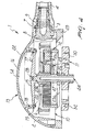
- the reference numeral 1 designates a pressure cleaner brush for washing surfaces.
- the brush 1 comprises a body 2, which is shaped like a half-shell and whose outer wall is crossed by a hole 3, which is connected to a rigid tube 4 that acts as a handle.
- the free end of the rigid tube 4 is provided with a connecting element 5, which allows to connect the brush 1 to a water supply system, such as for example the ordinary water mains, a surge tank, a pump or the like.
- a water supply system such as for example the ordinary water mains, a surge tank, a pump or the like.
- a vaned or bladed impeller 6 is rotatably supported inside the body 2 and can be turned, during use, by means of a jet of water that arrives from a nozzle 7, which is tangent with respect to said impeller and is associated with the body 2.
- Said nozzle is elongated and crosses the hole 3 from end to end, mutually connecting the rigid tube 4 and the body 2; it is in fact provided, at one end, with a head 8 that abuts against the internal surface of the body 2, and is associated, at the other end, with the rigid tube 4 by means of a screw-and-nut connection 9.
- the body 2 is provided with a circular opening 10, which is delimited by the mouth of the half-shell formed by said body; a rotating brush 11, actuated by the impeller 6 by interposing a gear system 12, protrudes from said opening.
- the brush 1 according to the invention comprises a tank 13 for containing a detergent fluid, which is associated with the body 2 on the opposite side with respect to the opening 10.
- the tank 13 is formed by a compartment 14, which is formed inside the body 2, can be accessed from outside, and in particular is delimited inside a recessed wall 15 of the body 2 and can be closed by means of a cover 16.
- Said recessed wall is cylindrical, with a circular cross-section and an axis that is perpendicular to the plane of arrangement of the opening 10.
- the cover 16 comprises a tubular side wall 17, which also has a circular cross-section, is closed at one end and can be inserted snugly in the recessed wall 15.
- the outer side of said side wall is threaded in order to allow the screwing of the cover 16 on three protruding elements 18, which are provided laterally, approximately at 120° to each other, on the recessed wall 15.
- the tank 13 is further provided with a plurality of passages 19 for the flow of the detergent fluid from the compartment 14 toward the opening 10, which pass through the recessed wall 15.
- the flow of the detergent fluid through said passages occurs by gravity, and in order to control the flow, the brush 1 is provided with means for adjusting the opening and closing of the aperture of said passages.
- said adjustment means comprise a flexible sealing body 20, which is formed by an annular gasket, which has the same diameter as the side wall 17 and is accommodated snugly in a circular slot formed on the recessed wall 15: in particular, the passages 19 are formed so as to pass through said recessed wall at said slot.
- the sealing body 20 is interposed between the recessed wall 15 and a portion 21 of the cover 16, which is formed by the open edge of the side wall 17, so that the screwing of the cover 16 is adapted to compress the sealing body 20, closing at least partially the passages 19.
- the brush 1 is provided with means for gripping said cover, which comprise for example a plurality of wings 22, which are provided so as to protrude on the outer surface of said cover.
- the wings 22 are distributed radially on said surface, forming a circular succession with a constant pitch, are slightly curved, and are anatomically contoured in order to facilitate the manual grip on the part of the operator.
- the gear system 12 that transmits motion from the impeller 6 to the rotating brush 11 is conveniently of the epicyclic type with a gear ratio of less than 1; it in fact comprises a first gear 23a with internal teeth, which can be associated rigidly with the body 2, and a second gear 23b, which has external teeth and can be associated rigidly and coaxially with the impeller 6; said gears can mesh together by way of the interposition of a third gear 23c, which also has external teeth and is supported rotatably by a carrier 24, which can be associated with the rotating brush 11.
- the first gear is associated with an annular support 25, which can be fixed to the body 2 at the edge of the opening 10 and is provided centrally with a hub 26 for supporting the carrier 24.
- Said carrier in fact comprises a shaft 27, which is supported rotatably, at one end, in the hub 26 and is inserted, at the other end, in a cylindrical cavity 28 formed in the recessed wall 15.
- the carrier 24 lies outside the dome 2; the end portion of the shaft 27 that lies opposite the cavity 28 in fact cantilevers out beyond the hub 26, and the rotating brush 11 is keyed thereon.
- said rotating brush comprises a base 30, on which there are a plurality of seats 31 for accommodating tufts of bristles, not shown in the figure because they are of a known type: in this regard, it is noted that said bristles advantageously can assume any shape and size according to the different requirements of use of the present invention.
- the brush 1 can be provided with a fixed brush, constituted by a series of bristles, also not shown in the figures, which are arranged coaxially around the rotating brush 11 and can be inserted in corresponding slots 32 that can be formed on the annular support 25.
Landscapes
- Brushes (AREA)
Abstract
Description
Claims (22)
- A pressure cleaner brush for washing surfaces, comprising a body (2) inside which a bladed impeller (6) is supported so that it can rotate, said impeller (6) being turned by a jet of water that arrives from a nozzle (7) that is associated with said body (2), said body (2) being provided with at least one opening (10) from which at least one rotating brush (11) actuated by said impeller (6) protrudes, characterized in that it comprises at least one tank (13) for containing a detergent fluid, said tank (13) being associated with said body (2).
- The brush according to claim 1, characterized in that said tank (13) is associated with said body (2) on the opposite side with respect to said opening (10).
- The brush according to one or more of the preceding claims, characterized in that said tank (13) is formed by a compartment (14) that is provided in said body (2) and can be accessed from outside.
- The brush according to one or more of the preceding claims, characterized in that said compartment (14) is formed inside a recessed wall (15) of said body (2) and can be closed with a cover (16).
- The brush according to one or more of the preceding claims, characterized in that said cover (16) comprises a substantially tubular side wall (17), which has a circular cross-section, is closed at one end, and can be inserted snugly in said recessed wall (15).
- The brush according to one or more of the preceding claims, characterized in that said side wall (17) is threaded on the outer side and can be screwed onto at least one protruding element (18) formed on said recessed wall (15).
- The brush according to one or more of the preceding claims, characterized in that said tank (13) is provided with at least one passage (19) for the flow of said detergent fluid from said compartment (14) toward said opening (10).
- The brush according to one or more of the preceding claims, characterized in that said passage (19) is formed in said recessed wall (15), said detergent fluid being adapted to pass through said passage (19) by gravity.
- The brush according to one or more of the preceding claims, characterized in that it comprises means (20) for adjusting the opening and closing of the aperture of said passage (19).
- The brush according to one or more of the preceding claims, characterized in that said adjustment means comprise at least one sealing body (20), which is flexible and interposed between said recessed wall (15) and at least one portion (21) of said cover (16) at said slot, the screwing of said cover (16) being adapted to compress said sealing body (20) so as to close said passage (19) at least partially.
- The brush according to claim 10, characterized in that said sealing body (20) is formed by at least one annular gasket, which has a diameter that is substantially equal to the diameter of said side wall (17) and is accommodated snugly in a corresponding slot formed in said recessed wall (15), said portion (21) of the cover (16) being formed by the open edge of said side wall (17).
- The brush according to one or more of the preceding claims, characterized in that it comprises means (22) for gripping said cover (16).
- The brush according to claim 12, characterized in that said grip means comprise at least one wing (22) that is formed so as to protrude on the outer surface of said cover (16).
- The brush according to claim 12, characterized in that it comprises a plurality of said wings (22), which are distributed substantially radially on said surface with a substantially constant pitch.
- The brush according to one or more of the preceding claims, characterized in that said rotating brush (11) is associated with said impeller (6) with the interposition of an epicyclic gear system (12).
- The brush according to one or more of the preceding claims, characterized in that said gear system (12) comprises a first gear (23a) with internal teeth, which is rigidly associable with said body (2), and a second gear (23b) with external teeth, which is rigidly associable and coaxial with respect to said impeller (6), said first and second gears (23a, 23b) meshing together by way of the interposition of at least one third gear (23c) with external teeth, which is supported by a carrier (24) that is associable with said rotating brush (11).
- The brush according to one or more of the preceding claims, characterized in that said first gear (23a) is associated with an annular support (25), which can be fixed to said body (2) at the edge of said opening (10).
- The brush according to claim 16, characterized in that said carrier (24) comprises a shaft (27), which is supported rotatably, at one end, by a hub (26) associated with said annular support (25) and, at the other end, in a cavity (28) formed in said body (2).
- The brush according to claim 18, characterized in that said shaft (27) supports rotatably said second gear (23b) and said impeller (6) adjacent to said recessed wall (15).
- The brush according to one or more of the claims 16-18, characterized in that said carrier (24) comprises a radial arm (29) associated with said shaft (27), said third gear (23c) being supported at the free end of said radial arm (29).
- The brush according to one or more of the claims 18-20, characterized in that said rotating brush (11) is keyed to the end portion of said shaft (27) that lies opposite said cavity (28), said end portion protruding in a cantilevered manner beyond said hub (26).
- The brush according to one or more of the preceding claims, characterized in that it comprises a fixed brush, which is associated with said annular support (25) and is arranged around said rotating brush (11) and substantially coaxially thereto.
Applications Claiming Priority (2)
| Application Number | Priority Date | Filing Date | Title |
|---|---|---|---|
| IT000329A ITMO20030329A1 (en) | 2003-12-03 | 2003-12-03 | CLEANING BRUSH FOR SURFACE WASHING. |
| ITMO20030329 | 2003-12-03 |
Publications (3)
| Publication Number | Publication Date |
|---|---|
| EP1537813A2 true EP1537813A2 (en) | 2005-06-08 |
| EP1537813A3 EP1537813A3 (en) | 2006-10-04 |
| EP1537813B1 EP1537813B1 (en) | 2012-04-18 |
Family
ID=34452274
Family Applications (1)
| Application Number | Title | Priority Date | Filing Date |
|---|---|---|---|
| EP04028231A Expired - Lifetime EP1537813B1 (en) | 2003-12-03 | 2004-11-29 | Pressure cleaner brush for washing surfaces |
Country Status (4)
| Country | Link |
|---|---|
| US (1) | US7337487B2 (en) |
| EP (1) | EP1537813B1 (en) |
| AT (1) | ATE553685T1 (en) |
| IT (1) | ITMO20030329A1 (en) |
Cited By (4)
| Publication number | Priority date | Publication date | Assignee | Title |
|---|---|---|---|---|
| CN102961080A (en) * | 2012-12-18 | 2013-03-13 | 湖南科技大学 | Multifunctional glass cleaning robot and control method |
| CN104176012A (en) * | 2014-07-28 | 2014-12-03 | 宁波富斯乐机械制造有限公司 | Energy-saving high-pressure cleaning machine |
| IT201600113411A1 (en) * | 2016-11-10 | 2018-05-10 | Behor Zitun | HYDRAULIC DRIVE MASSAGING DEVICE |
| IT202000003206A1 (en) * | 2020-02-18 | 2021-08-18 | Aeffe S R L | Underwater robot with rotating brush for the treatment of submerged surfaces |
Families Citing this family (14)
| Publication number | Priority date | Publication date | Assignee | Title |
|---|---|---|---|---|
| ITRE20040135A1 (en) * | 2004-11-09 | 2005-02-09 | Gf Srl | WASHING BRUSH WITH DETERGENT DOSER |
| DE102006007442A1 (en) * | 2006-02-17 | 2007-08-23 | BSH Bosch und Siemens Hausgeräte GmbH | Cleaning device for a component of a household laundry drier |
| AU2008200975B2 (en) * | 2007-03-05 | 2012-09-27 | Bissell Inc. | Accessory tool for a vacuum cleaner |
| US9186028B2 (en) | 2007-03-05 | 2015-11-17 | Bissell Homecare, Inc. | Accessory tool for a vacuum cleaner |
| EP2625995A1 (en) * | 2012-02-13 | 2013-08-14 | E.M.M.P. S.r.l. | Device for cleaning surfaces and the like |
| CN104083130B (en) * | 2014-07-01 | 2017-01-04 | 张周新 | A kind of wall cleans device |
| US10750849B2 (en) | 2015-04-03 | 2020-08-25 | Water Pik, Inc. | Skin cleansing and massaging system |
| AU2016321308A1 (en) | 2015-09-11 | 2018-04-19 | Simon E. SMITH | Flexible rotary brush hub |
| USD828694S1 (en) | 2016-04-04 | 2018-09-18 | Water Pik, Inc. | Handheld skin exfoliator |
| USD854654S1 (en) | 2017-11-13 | 2019-07-23 | Water Pik, Inc. | Bracket for a handheld cleansing device |
| USD861830S1 (en) | 2017-11-13 | 2019-10-01 | Water Pik, Inc. | Handheld cleansing device |
| USD904039S1 (en) | 2017-11-13 | 2020-12-08 | Water Pik, Inc. | Shower accessory hanger |
| USD898374S1 (en) | 2018-07-02 | 2020-10-13 | Water Pik, Inc. | Skin cleansing brush |
| CN109076966B (en) * | 2018-09-18 | 2023-07-04 | 南宁利腾农业科技有限公司 | Dust-removing cleaning tool |
Family Cites Families (24)
| Publication number | Priority date | Publication date | Assignee | Title |
|---|---|---|---|---|
| US3540072A (en) * | 1964-08-03 | 1970-11-17 | Sunbeam Corp | Floor conditioner |
| US3486532A (en) * | 1966-08-04 | 1969-12-30 | Tigers Rubber Co Ltd | Method of making a corrugated hose |
| US3460184A (en) * | 1966-11-15 | 1969-08-12 | Hoover Co | Automatic conversion system for a scrubbing and liquid pickup appliance |
| US3520012A (en) * | 1968-02-20 | 1970-07-14 | Hoover Co | Squeegee nozzle for wet pickup suction cleaner |
| US3572393A (en) * | 1969-10-27 | 1971-03-23 | Central Research Lab Inc | Collapsible corrugated tube |
| AU531291B2 (en) * | 1979-08-13 | 1983-08-18 | Sylon International Pty. Ltd. | Dispensing apparatus |
| US4429362A (en) * | 1981-06-18 | 1984-01-31 | The Bendix Corporation | Data buffer operating in response to computer halt signal |
| US4513466A (en) * | 1984-09-24 | 1985-04-30 | Hempe Manufacturing Co. | Water-powered brush |
| US5007127A (en) * | 1988-10-26 | 1991-04-16 | Gordon S.N.C. Di Bizzarri Paolo E C. | Hydrobrush with speed-reducer of the epicyclic type |
| US5129121A (en) * | 1989-09-18 | 1992-07-14 | Gideon Gelman | Turbine driven rotating brush |
| US5331715A (en) * | 1992-06-04 | 1994-07-26 | Matsushita Floor Care Company | Two motor upright vacuum cleaner |
| US5500977A (en) * | 1994-01-14 | 1996-03-26 | The Hoover Company | Upright carpet extractor |
| US5443362A (en) * | 1994-03-16 | 1995-08-22 | The Hoover Company | Air turbine |
| GB9503185D0 (en) * | 1995-02-18 | 1995-04-05 | Vax Ltd | Cleaning head |
| US6167587B1 (en) * | 1997-07-09 | 2001-01-02 | Bissell Homecare, Inc. | Upright extraction cleaning machine |
| US5619766A (en) * | 1996-02-15 | 1997-04-15 | Zhadanov; Sam | Water driven cleaning device |
| GB9603745D0 (en) * | 1996-02-22 | 1996-04-24 | Vax Ltd | Apparatus for cleaning floors, carpets and the like |
| US5911256A (en) * | 1998-01-12 | 1999-06-15 | Tsai; James | Brush having a bristled head capable of being powered by water to swivel |
| US6253942B1 (en) * | 1998-04-30 | 2001-07-03 | Richard I. Elias | Easy opening, screw cap for threaded opening type containers |
| US6634050B1 (en) * | 2000-02-04 | 2003-10-21 | Luis A. Barboza | Cleaning apparatus |
| GB2369560B (en) * | 2000-11-24 | 2002-12-18 | Easy Do Products Ltd | Improvements to implements for cleaning polishing or sanding |
| US6640386B2 (en) * | 2001-09-18 | 2003-11-04 | The Hoover Company | Floor cleaning unit with a brush assembly |
| GB2387773A (en) * | 2002-04-26 | 2003-10-29 | Gordon Chih | Water flow-driven rotary and vibrational cleaning brush |
| TW547032U (en) * | 2002-04-26 | 2003-08-11 | Gordon Chih | Cleaning brush driven to rotate and vibrated by water flow |
-
2003
- 2003-12-03 IT IT000329A patent/ITMO20030329A1/en unknown
-
2004
- 2004-11-29 AT AT04028231T patent/ATE553685T1/en active
- 2004-11-29 EP EP04028231A patent/EP1537813B1/en not_active Expired - Lifetime
- 2004-12-02 US US11/000,963 patent/US7337487B2/en not_active Expired - Fee Related
Cited By (6)
| Publication number | Priority date | Publication date | Assignee | Title |
|---|---|---|---|---|
| CN102961080A (en) * | 2012-12-18 | 2013-03-13 | 湖南科技大学 | Multifunctional glass cleaning robot and control method |
| CN102961080B (en) * | 2012-12-18 | 2015-07-08 | 湖南科技大学 | Multifunctional glass cleaning robot and control method |
| CN104176012A (en) * | 2014-07-28 | 2014-12-03 | 宁波富斯乐机械制造有限公司 | Energy-saving high-pressure cleaning machine |
| CN104176012B (en) * | 2014-07-28 | 2016-02-24 | 宁波富斯乐机械制造有限公司 | A kind of energy-saving and high-pressure cleaning machine |
| IT201600113411A1 (en) * | 2016-11-10 | 2018-05-10 | Behor Zitun | HYDRAULIC DRIVE MASSAGING DEVICE |
| IT202000003206A1 (en) * | 2020-02-18 | 2021-08-18 | Aeffe S R L | Underwater robot with rotating brush for the treatment of submerged surfaces |
Also Published As
| Publication number | Publication date |
|---|---|
| ITMO20030329A1 (en) | 2005-06-04 |
| EP1537813A3 (en) | 2006-10-04 |
| US20050125921A1 (en) | 2005-06-16 |
| US7337487B2 (en) | 2008-03-04 |
| EP1537813B1 (en) | 2012-04-18 |
| ATE553685T1 (en) | 2012-05-15 |
Similar Documents
| Publication | Publication Date | Title |
|---|---|---|
| US7337487B2 (en) | Pressure cleaner brush for washing surfaces | |
| US4370771A (en) | Water-driven brush | |
| US6595440B2 (en) | Handheld fluid powered spray device with detachable accessories | |
| CN109199267B (en) | Water washing cleaning device | |
| US20110121105A1 (en) | Multi-positional handheld fluid powered spray device with detacheable accessories | |
| US3909867A (en) | Hydraulic pressure driven rotary toothbrush | |
| CN108784566B (en) | Floor cleaning appliance | |
| CN107232804B (en) | Multifunctional cabinet with integrated dishwasher | |
| CN210207264U (en) | Washing and protecting article carrier and shower | |
| CN208661439U (en) | A kind of discharging device, water unit and the movable part used in discharging device | |
| CN214974007U (en) | Water suspending agent batching reation kettle | |
| CN214320565U (en) | an electric shower | |
| US2955304A (en) | Machine for washing drinking glasses and the like | |
| CN212630942U (en) | Oral cavity cleaning appliance handle and oral cavity cleaning appliance | |
| CN210643836U (en) | Automatic go out electric bath brush of liquid | |
| CN115177167B (en) | Water outlet device and adapter thereof | |
| CN109771066B (en) | A kind of energy-saving and environment-friendly electric tooth washing device and method | |
| CN212308089U (en) | Oral cavity cleaning appliance handle and oral cavity cleaning appliance | |
| US2563528A (en) | hamilton | |
| EP0860141A2 (en) | Liquid detergent dispenser for dishwashers | |
| KR200312929Y1 (en) | Automaic cleaning device on the windowpane | |
| CN217659505U (en) | Shower spraying device for cleaning roller assembly | |
| CN113083582A (en) | Electrostatic spraying device for automobile hub by micro-arc oxidation technology | |
| CN223987852U (en) | Cleaning brush and cleaning water tank | |
| CN219089071U (en) | Portable hydrodynamic toilet brush |
Legal Events
| Date | Code | Title | Description |
|---|---|---|---|
| PUAI | Public reference made under article 153(3) epc to a published international application that has entered the european phase |
Free format text: ORIGINAL CODE: 0009012 |
|
| AK | Designated contracting states |
Kind code of ref document: A2 Designated state(s): AT BE BG CH CY CZ DE DK EE ES FI FR GB GR HU IE IS IT LI LU MC NL PL PT RO SE SI SK TR |
|
| AX | Request for extension of the european patent |
Extension state: AL HR LT LV MK YU |
|
| PUAL | Search report despatched |
Free format text: ORIGINAL CODE: 0009013 |
|
| AK | Designated contracting states |
Kind code of ref document: A3 Designated state(s): AT BE BG CH CY CZ DE DK EE ES FI FR GB GR HU IE IS IT LI LU MC NL PL PT RO SE SI SK TR |
|
| AX | Request for extension of the european patent |
Extension state: AL HR LT LV MK YU |
|
| 17P | Request for examination filed |
Effective date: 20061103 |
|
| AKX | Designation fees paid |
Designated state(s): AT BE BG CH CY CZ DE DK EE ES FI FR GB GR HU IE IS IT LI LU MC NL PL PT RO SE SI SK TR |
|
| 17Q | First examination report despatched |
Effective date: 20071019 |
|
| REG | Reference to a national code |
Ref country code: DE Ref legal event code: R079 Ref document number: 602004037387 Country of ref document: DE Free format text: PREVIOUS MAIN CLASS: A47L0001080000 Ipc: A47L0011030000 |
|
| GRAP | Despatch of communication of intention to grant a patent |
Free format text: ORIGINAL CODE: EPIDOSNIGR1 |
|
| RIC1 | Information provided on ipc code assigned before grant |
Ipc: A47L 11/03 20060101AFI20111012BHEP Ipc: B08B 1/04 20060101ALI20111012BHEP Ipc: A46B 13/06 20060101ALI20111012BHEP |
|
| GRAS | Grant fee paid |
Free format text: ORIGINAL CODE: EPIDOSNIGR3 |
|
| GRAA | (expected) grant |
Free format text: ORIGINAL CODE: 0009210 |
|
| AK | Designated contracting states |
Kind code of ref document: B1 Designated state(s): AT BE BG CH CY CZ DE DK EE ES FI FR GB GR HU IE IS IT LI LU MC NL PL PT RO SE SI SK TR |
|
| REG | Reference to a national code |
Ref country code: GB Ref legal event code: FG4D |
|
| REG | Reference to a national code |
Ref country code: CH Ref legal event code: EP |
|
| REG | Reference to a national code |
Ref country code: IE Ref legal event code: FG4D |
|
| REG | Reference to a national code |
Ref country code: AT Ref legal event code: REF Ref document number: 553685 Country of ref document: AT Kind code of ref document: T Effective date: 20120515 |
|
| REG | Reference to a national code |
Ref country code: DE Ref legal event code: R096 Ref document number: 602004037387 Country of ref document: DE Effective date: 20120614 |
|
| REG | Reference to a national code |
Ref country code: NL Ref legal event code: VDEP Effective date: 20120418 |
|
| REG | Reference to a national code |
Ref country code: AT Ref legal event code: MK05 Ref document number: 553685 Country of ref document: AT Kind code of ref document: T Effective date: 20120418 |
|
| PG25 | Lapsed in a contracting state [announced via postgrant information from national office to epo] |
Ref country code: SE Free format text: LAPSE BECAUSE OF FAILURE TO SUBMIT A TRANSLATION OF THE DESCRIPTION OR TO PAY THE FEE WITHIN THE PRESCRIBED TIME-LIMIT Effective date: 20120418 Ref country code: FI Free format text: LAPSE BECAUSE OF FAILURE TO SUBMIT A TRANSLATION OF THE DESCRIPTION OR TO PAY THE FEE WITHIN THE PRESCRIBED TIME-LIMIT Effective date: 20120418 Ref country code: PL Free format text: LAPSE BECAUSE OF FAILURE TO SUBMIT A TRANSLATION OF THE DESCRIPTION OR TO PAY THE FEE WITHIN THE PRESCRIBED TIME-LIMIT Effective date: 20120418 Ref country code: IS Free format text: LAPSE BECAUSE OF FAILURE TO SUBMIT A TRANSLATION OF THE DESCRIPTION OR TO PAY THE FEE WITHIN THE PRESCRIBED TIME-LIMIT Effective date: 20120818 Ref country code: CY Free format text: LAPSE BECAUSE OF FAILURE TO SUBMIT A TRANSLATION OF THE DESCRIPTION OR TO PAY THE FEE WITHIN THE PRESCRIBED TIME-LIMIT Effective date: 20120418 |
|
| PG25 | Lapsed in a contracting state [announced via postgrant information from national office to epo] |
Ref country code: PT Free format text: LAPSE BECAUSE OF FAILURE TO SUBMIT A TRANSLATION OF THE DESCRIPTION OR TO PAY THE FEE WITHIN THE PRESCRIBED TIME-LIMIT Effective date: 20120820 Ref country code: SI Free format text: LAPSE BECAUSE OF FAILURE TO SUBMIT A TRANSLATION OF THE DESCRIPTION OR TO PAY THE FEE WITHIN THE PRESCRIBED TIME-LIMIT Effective date: 20120418 Ref country code: GR Free format text: LAPSE BECAUSE OF FAILURE TO SUBMIT A TRANSLATION OF THE DESCRIPTION OR TO PAY THE FEE WITHIN THE PRESCRIBED TIME-LIMIT Effective date: 20120719 |
|
| PG25 | Lapsed in a contracting state [announced via postgrant information from national office to epo] |
Ref country code: BE Free format text: LAPSE BECAUSE OF FAILURE TO SUBMIT A TRANSLATION OF THE DESCRIPTION OR TO PAY THE FEE WITHIN THE PRESCRIBED TIME-LIMIT Effective date: 20120418 |
|
| PG25 | Lapsed in a contracting state [announced via postgrant information from national office to epo] |
Ref country code: DK Free format text: LAPSE BECAUSE OF FAILURE TO SUBMIT A TRANSLATION OF THE DESCRIPTION OR TO PAY THE FEE WITHIN THE PRESCRIBED TIME-LIMIT Effective date: 20120418 Ref country code: RO Free format text: LAPSE BECAUSE OF FAILURE TO SUBMIT A TRANSLATION OF THE DESCRIPTION OR TO PAY THE FEE WITHIN THE PRESCRIBED TIME-LIMIT Effective date: 20120418 Ref country code: SK Free format text: LAPSE BECAUSE OF FAILURE TO SUBMIT A TRANSLATION OF THE DESCRIPTION OR TO PAY THE FEE WITHIN THE PRESCRIBED TIME-LIMIT Effective date: 20120418 Ref country code: AT Free format text: LAPSE BECAUSE OF FAILURE TO SUBMIT A TRANSLATION OF THE DESCRIPTION OR TO PAY THE FEE WITHIN THE PRESCRIBED TIME-LIMIT Effective date: 20120418 Ref country code: EE Free format text: LAPSE BECAUSE OF FAILURE TO SUBMIT A TRANSLATION OF THE DESCRIPTION OR TO PAY THE FEE WITHIN THE PRESCRIBED TIME-LIMIT Effective date: 20120418 Ref country code: CZ Free format text: LAPSE BECAUSE OF FAILURE TO SUBMIT A TRANSLATION OF THE DESCRIPTION OR TO PAY THE FEE WITHIN THE PRESCRIBED TIME-LIMIT Effective date: 20120418 Ref country code: NL Free format text: LAPSE BECAUSE OF FAILURE TO SUBMIT A TRANSLATION OF THE DESCRIPTION OR TO PAY THE FEE WITHIN THE PRESCRIBED TIME-LIMIT Effective date: 20120418 |
|
| PLBE | No opposition filed within time limit |
Free format text: ORIGINAL CODE: 0009261 |
|
| STAA | Information on the status of an ep patent application or granted ep patent |
Free format text: STATUS: NO OPPOSITION FILED WITHIN TIME LIMIT |
|
| PG25 | Lapsed in a contracting state [announced via postgrant information from national office to epo] |
Ref country code: IT Free format text: LAPSE BECAUSE OF FAILURE TO SUBMIT A TRANSLATION OF THE DESCRIPTION OR TO PAY THE FEE WITHIN THE PRESCRIBED TIME-LIMIT Effective date: 20120418 |
|
| 26N | No opposition filed |
Effective date: 20130121 |
|
| PG25 | Lapsed in a contracting state [announced via postgrant information from national office to epo] |
Ref country code: ES Free format text: LAPSE BECAUSE OF FAILURE TO SUBMIT A TRANSLATION OF THE DESCRIPTION OR TO PAY THE FEE WITHIN THE PRESCRIBED TIME-LIMIT Effective date: 20120729 |
|
| REG | Reference to a national code |
Ref country code: DE Ref legal event code: R097 Ref document number: 602004037387 Country of ref document: DE Effective date: 20130121 |
|
| REG | Reference to a national code |
Ref country code: CH Ref legal event code: PL |
|
| GBPC | Gb: european patent ceased through non-payment of renewal fee |
Effective date: 20121129 |
|
| PG25 | Lapsed in a contracting state [announced via postgrant information from national office to epo] |
Ref country code: BG Free format text: LAPSE BECAUSE OF FAILURE TO SUBMIT A TRANSLATION OF THE DESCRIPTION OR TO PAY THE FEE WITHIN THE PRESCRIBED TIME-LIMIT Effective date: 20120718 Ref country code: CH Free format text: LAPSE BECAUSE OF NON-PAYMENT OF DUE FEES Effective date: 20121130 Ref country code: LI Free format text: LAPSE BECAUSE OF NON-PAYMENT OF DUE FEES Effective date: 20121130 |
|
| REG | Reference to a national code |
Ref country code: FR Ref legal event code: ST Effective date: 20130731 |
|
| REG | Reference to a national code |
Ref country code: IE Ref legal event code: MM4A |
|
| REG | Reference to a national code |
Ref country code: DE Ref legal event code: R119 Ref document number: 602004037387 Country of ref document: DE Effective date: 20130601 |
|
| PG25 | Lapsed in a contracting state [announced via postgrant information from national office to epo] |
Ref country code: DE Free format text: LAPSE BECAUSE OF NON-PAYMENT OF DUE FEES Effective date: 20130601 Ref country code: IE Free format text: LAPSE BECAUSE OF NON-PAYMENT OF DUE FEES Effective date: 20121129 |
|
| PG25 | Lapsed in a contracting state [announced via postgrant information from national office to epo] |
Ref country code: FR Free format text: LAPSE BECAUSE OF NON-PAYMENT OF DUE FEES Effective date: 20121130 Ref country code: GB Free format text: LAPSE BECAUSE OF NON-PAYMENT OF DUE FEES Effective date: 20121129 |
|
| PG25 | Lapsed in a contracting state [announced via postgrant information from national office to epo] |
Ref country code: MC Free format text: LAPSE BECAUSE OF NON-PAYMENT OF DUE FEES Effective date: 20121130 Ref country code: TR Free format text: LAPSE BECAUSE OF FAILURE TO SUBMIT A TRANSLATION OF THE DESCRIPTION OR TO PAY THE FEE WITHIN THE PRESCRIBED TIME-LIMIT Effective date: 20120418 |
|
| PG25 | Lapsed in a contracting state [announced via postgrant information from national office to epo] |
Ref country code: LU Free format text: LAPSE BECAUSE OF NON-PAYMENT OF DUE FEES Effective date: 20121129 |
|
| PG25 | Lapsed in a contracting state [announced via postgrant information from national office to epo] |
Ref country code: HU Free format text: LAPSE BECAUSE OF FAILURE TO SUBMIT A TRANSLATION OF THE DESCRIPTION OR TO PAY THE FEE WITHIN THE PRESCRIBED TIME-LIMIT Effective date: 20041129 |