EP1537591B1 - Method of handling a fluid and a device therefor. - Google Patents
Method of handling a fluid and a device therefor. Download PDFInfo
- Publication number
- EP1537591B1 EP1537591B1 EP03812413A EP03812413A EP1537591B1 EP 1537591 B1 EP1537591 B1 EP 1537591B1 EP 03812413 A EP03812413 A EP 03812413A EP 03812413 A EP03812413 A EP 03812413A EP 1537591 B1 EP1537591 B1 EP 1537591B1
- Authority
- EP
- European Patent Office
- Prior art keywords
- voltage
- electrodes
- corona
- current
- amplitude
- Prior art date
- Legal status (The legal status is an assumption and is not a legal conclusion. Google has not performed a legal analysis and makes no representation as to the accuracy of the status listed.)
- Expired - Lifetime
Links
- 239000012530 fluid Substances 0.000 title claims description 122
- 238000000034 method Methods 0.000 title claims description 45
- 239000000463 material Substances 0.000 claims description 26
- 230000008859 change Effects 0.000 claims description 9
- 230000000295 complement effect Effects 0.000 claims description 7
- 230000004044 response Effects 0.000 claims description 4
- 238000004804 winding Methods 0.000 description 39
- 230000005684 electric field Effects 0.000 description 36
- 150000002500 ions Chemical class 0.000 description 31
- 238000010586 diagram Methods 0.000 description 29
- 239000003990 capacitor Substances 0.000 description 25
- 230000001360 synchronised effect Effects 0.000 description 20
- 230000007423 decrease Effects 0.000 description 18
- 230000001133 acceleration Effects 0.000 description 17
- 239000002245 particle Substances 0.000 description 17
- CBENFWSGALASAD-UHFFFAOYSA-N Ozone Chemical compound [O-][O+]=O CBENFWSGALASAD-UHFFFAOYSA-N 0.000 description 16
- 238000004519 manufacturing process Methods 0.000 description 16
- 230000015556 catabolic process Effects 0.000 description 15
- 230000008569 process Effects 0.000 description 14
- 230000008901 benefit Effects 0.000 description 11
- 230000003071 parasitic effect Effects 0.000 description 10
- 238000001514 detection method Methods 0.000 description 9
- 230000003247 decreasing effect Effects 0.000 description 8
- 230000002829 reductive effect Effects 0.000 description 8
- 235000014676 Phragmites communis Nutrition 0.000 description 7
- 239000012717 electrostatic precipitator Substances 0.000 description 7
- 238000013461 design Methods 0.000 description 6
- 238000013459 approach Methods 0.000 description 5
- 230000007812 deficiency Effects 0.000 description 5
- 230000000694 effects Effects 0.000 description 5
- 230000000977 initiatory effect Effects 0.000 description 5
- 230000000670 limiting effect Effects 0.000 description 5
- 229910052751 metal Inorganic materials 0.000 description 5
- 239000002184 metal Substances 0.000 description 5
- 238000010248 power generation Methods 0.000 description 5
- 230000006378 damage Effects 0.000 description 4
- 238000001914 filtration Methods 0.000 description 4
- 239000004033 plastic Substances 0.000 description 4
- 239000004065 semiconductor Substances 0.000 description 4
- 239000000243 solution Substances 0.000 description 4
- HEMHJVSKTPXQMS-UHFFFAOYSA-M Sodium hydroxide Chemical compound [OH-].[Na+] HEMHJVSKTPXQMS-UHFFFAOYSA-M 0.000 description 3
- 239000004020 conductor Substances 0.000 description 3
- 239000000356 contaminant Substances 0.000 description 3
- 238000011109 contamination Methods 0.000 description 3
- 238000002242 deionisation method Methods 0.000 description 3
- 239000000428 dust Substances 0.000 description 3
- 238000005516 engineering process Methods 0.000 description 3
- 230000006870 function Effects 0.000 description 3
- 230000006872 improvement Effects 0.000 description 3
- 229910052710 silicon Inorganic materials 0.000 description 3
- 239000010703 silicon Substances 0.000 description 3
- 239000007787 solid Substances 0.000 description 3
- 230000001052 transient effect Effects 0.000 description 3
- JBRZTFJDHDCESZ-UHFFFAOYSA-N AsGa Chemical compound [As]#[Ga] JBRZTFJDHDCESZ-UHFFFAOYSA-N 0.000 description 2
- 229910052582 BN Inorganic materials 0.000 description 2
- PZNSFCLAULLKQX-UHFFFAOYSA-N Boron nitride Chemical compound N#B PZNSFCLAULLKQX-UHFFFAOYSA-N 0.000 description 2
- OKTJSMMVPCPJKN-UHFFFAOYSA-N Carbon Chemical compound [C] OKTJSMMVPCPJKN-UHFFFAOYSA-N 0.000 description 2
- 229910001218 Gallium arsenide Inorganic materials 0.000 description 2
- GPXJNWSHGFTCBW-UHFFFAOYSA-N Indium phosphide Chemical compound [In]#P GPXJNWSHGFTCBW-UHFFFAOYSA-N 0.000 description 2
- XUIMIQQOPSSXEZ-UHFFFAOYSA-N Silicon Chemical compound [Si] XUIMIQQOPSSXEZ-UHFFFAOYSA-N 0.000 description 2
- FAPWRFPIFSIZLT-UHFFFAOYSA-M Sodium chloride Chemical compound [Na+].[Cl-] FAPWRFPIFSIZLT-UHFFFAOYSA-M 0.000 description 2
- 230000002411 adverse Effects 0.000 description 2
- 230000009286 beneficial effect Effects 0.000 description 2
- UHYPYGJEEGLRJD-UHFFFAOYSA-N cadmium(2+);selenium(2-) Chemical compound [Se-2].[Cd+2] UHYPYGJEEGLRJD-UHFFFAOYSA-N 0.000 description 2
- 238000004364 calculation method Methods 0.000 description 2
- 229910052799 carbon Inorganic materials 0.000 description 2
- 239000000919 ceramic Substances 0.000 description 2
- 230000008878 coupling Effects 0.000 description 2
- 238000010168 coupling process Methods 0.000 description 2
- 238000005859 coupling reaction Methods 0.000 description 2
- 230000001351 cycling effect Effects 0.000 description 2
- 230000001419 dependent effect Effects 0.000 description 2
- 230000006866 deterioration Effects 0.000 description 2
- 238000009826 distribution Methods 0.000 description 2
- 230000008030 elimination Effects 0.000 description 2
- 230000007613 environmental effect Effects 0.000 description 2
- 230000002401 inhibitory effect Effects 0.000 description 2
- 230000001788 irregular Effects 0.000 description 2
- 238000011068 loading method Methods 0.000 description 2
- 239000012716 precipitator Substances 0.000 description 2
- 230000002265 prevention Effects 0.000 description 2
- 230000009467 reduction Effects 0.000 description 2
- 239000005060 rubber Substances 0.000 description 2
- 230000035939 shock Effects 0.000 description 2
- HBMJWWWQQXIZIP-UHFFFAOYSA-N silicon carbide Chemical compound [Si+]#[C-] HBMJWWWQQXIZIP-UHFFFAOYSA-N 0.000 description 2
- 229910010271 silicon carbide Inorganic materials 0.000 description 2
- 239000011343 solid material Substances 0.000 description 2
- 208000032484 Accidental exposure to product Diseases 0.000 description 1
- 206010014405 Electrocution Diseases 0.000 description 1
- 241000238631 Hexapoda Species 0.000 description 1
- GRYLNZFGIOXLOG-UHFFFAOYSA-N Nitric acid Chemical compound O[N+]([O-])=O GRYLNZFGIOXLOG-UHFFFAOYSA-N 0.000 description 1
- 206010035148 Plague Diseases 0.000 description 1
- ATJFFYVFTNAWJD-UHFFFAOYSA-N Tin Chemical compound [Sn] ATJFFYVFTNAWJD-UHFFFAOYSA-N 0.000 description 1
- 208000027418 Wounds and injury Diseases 0.000 description 1
- 241000607479 Yersinia pestis Species 0.000 description 1
- 231100000818 accidental exposure Toxicity 0.000 description 1
- 230000009471 action Effects 0.000 description 1
- 230000032683 aging Effects 0.000 description 1
- 230000004075 alteration Effects 0.000 description 1
- 230000009118 appropriate response Effects 0.000 description 1
- 239000007864 aqueous solution Substances 0.000 description 1
- 238000003491 array Methods 0.000 description 1
- QVGXLLKOCUKJST-UHFFFAOYSA-N atomic oxygen Chemical compound [O] QVGXLLKOCUKJST-UHFFFAOYSA-N 0.000 description 1
- 238000006243 chemical reaction Methods 0.000 description 1
- 150000001875 compounds Chemical class 0.000 description 1
- 238000010276 construction Methods 0.000 description 1
- 238000006731 degradation reaction Methods 0.000 description 1
- 230000000593 degrading effect Effects 0.000 description 1
- 239000003989 dielectric material Substances 0.000 description 1
- 230000008278 dynamic mechanism Effects 0.000 description 1
- 230000005686 electrostatic field Effects 0.000 description 1
- 238000005367 electrostatic precipitation Methods 0.000 description 1
- 238000003379 elimination reaction Methods 0.000 description 1
- 238000005265 energy consumption Methods 0.000 description 1
- 230000004907 flux Effects 0.000 description 1
- 239000007789 gas Substances 0.000 description 1
- 229910052732 germanium Inorganic materials 0.000 description 1
- GNPVGFCGXDBREM-UHFFFAOYSA-N germanium atom Chemical compound [Ge] GNPVGFCGXDBREM-UHFFFAOYSA-N 0.000 description 1
- 239000012535 impurity Substances 0.000 description 1
- 208000014674 injury Diseases 0.000 description 1
- 239000011810 insulating material Substances 0.000 description 1
- 230000003993 interaction Effects 0.000 description 1
- 238000005468 ion implantation Methods 0.000 description 1
- 238000002955 isolation Methods 0.000 description 1
- 239000007788 liquid Substances 0.000 description 1
- 238000005259 measurement Methods 0.000 description 1
- 230000007246 mechanism Effects 0.000 description 1
- 230000000116 mitigating effect Effects 0.000 description 1
- 230000004048 modification Effects 0.000 description 1
- 238000012986 modification Methods 0.000 description 1
- -1 moisture Substances 0.000 description 1
- 238000012544 monitoring process Methods 0.000 description 1
- 229910017604 nitric acid Inorganic materials 0.000 description 1
- VIKNJXKGJWUCNN-XGXHKTLJSA-N norethisterone Chemical compound O=C1CC[C@@H]2[C@H]3CC[C@](C)([C@](CC4)(O)C#C)[C@@H]4[C@@H]3CCC2=C1 VIKNJXKGJWUCNN-XGXHKTLJSA-N 0.000 description 1
- 229910052760 oxygen Inorganic materials 0.000 description 1
- 239000001301 oxygen Substances 0.000 description 1
- 230000010363 phase shift Effects 0.000 description 1
- 238000012545 processing Methods 0.000 description 1
- 230000000750 progressive effect Effects 0.000 description 1
- 238000010791 quenching Methods 0.000 description 1
- 230000000171 quenching effect Effects 0.000 description 1
- 230000035945 sensitivity Effects 0.000 description 1
- 238000004904 shortening Methods 0.000 description 1
- 239000011780 sodium chloride Substances 0.000 description 1
- 239000007785 strong electrolyte Substances 0.000 description 1
- 239000000126 substance Substances 0.000 description 1
- 230000003319 supportive effect Effects 0.000 description 1
- 230000001629 suppression Effects 0.000 description 1
- 230000002459 sustained effect Effects 0.000 description 1
- 239000008399 tap water Substances 0.000 description 1
- 235000020679 tap water Nutrition 0.000 description 1
- 229910052718 tin Inorganic materials 0.000 description 1
- 238000012546 transfer Methods 0.000 description 1
- XLYOFNOQVPJJNP-UHFFFAOYSA-N water Substances O XLYOFNOQVPJJNP-UHFFFAOYSA-N 0.000 description 1
Images


Classifications
-
- B—PERFORMING OPERATIONS; TRANSPORTING
- B03—SEPARATION OF SOLID MATERIALS USING LIQUIDS OR USING PNEUMATIC TABLES OR JIGS; MAGNETIC OR ELECTROSTATIC SEPARATION OF SOLID MATERIALS FROM SOLID MATERIALS OR FLUIDS; SEPARATION BY HIGH-VOLTAGE ELECTRIC FIELDS
- B03C—MAGNETIC OR ELECTROSTATIC SEPARATION OF SOLID MATERIALS FROM SOLID MATERIALS OR FLUIDS; SEPARATION BY HIGH-VOLTAGE ELECTRIC FIELDS
- B03C3/00—Separating dispersed particles from gases or vapour, e.g. air, by electrostatic effect
- B03C3/34—Constructional details or accessories or operation thereof
- B03C3/66—Applications of electricity supply techniques
- B03C3/68—Control systems therefor
-
- H—ELECTRICITY
- H05—ELECTRIC TECHNIQUES NOT OTHERWISE PROVIDED FOR
- H05H—PLASMA TECHNIQUE; PRODUCTION OF ACCELERATED ELECTRICALLY-CHARGED PARTICLES OR OF NEUTRONS; PRODUCTION OR ACCELERATION OF NEUTRAL MOLECULAR OR ATOMIC BEAMS
- H05H1/00—Generating plasma; Handling plasma
- H05H1/24—Generating plasma
- H05H1/47—Generating plasma using corona discharges
- H05H1/471—Pointed electrodes
-
- B—PERFORMING OPERATIONS; TRANSPORTING
- B03—SEPARATION OF SOLID MATERIALS USING LIQUIDS OR USING PNEUMATIC TABLES OR JIGS; MAGNETIC OR ELECTROSTATIC SEPARATION OF SOLID MATERIALS FROM SOLID MATERIALS OR FLUIDS; SEPARATION BY HIGH-VOLTAGE ELECTRIC FIELDS
- B03C—MAGNETIC OR ELECTROSTATIC SEPARATION OF SOLID MATERIALS FROM SOLID MATERIALS OR FLUIDS; SEPARATION BY HIGH-VOLTAGE ELECTRIC FIELDS
- B03C2201/00—Details of magnetic or electrostatic separation
- B03C2201/14—Details of magnetic or electrostatic separation the gas being moved electro-kinetically
Definitions
- the invention relates to a method and device for the corona discharge generation and in particular to method of and devices for fluid acceleration to provide velocity and momentum to a fluids, especially to air, through the use of ions and electrical fields for the movement and control of such fluids.
- corona discharge may be used for generating ions and charging particles.
- Such methods are widely used in electrostatic precipitators and electric wind machines as described in Applied Electrostatic Precipitation published by Chapman & Hall (1997 ).
- the corona discharge device may be generated by application of a high voltage to pairs of electrodes, e.g., a corona discharge electrode and an attractor electrode. Therein a corona discharge is generated by application of a high voltage power source to pairs of electrodes.
- the electrodes are configured and arranged to generate a noun-uniform electric field proxite one of the electrodes (called a corona discharge electrode) so as to generate a corona and a resultant corona current toward a nearby complementary electrode (called a collector or attractor electrode).
- a corona discharge electrode a noun-uniform electric field proxite one of the electrodes
- a collector or attractor electrode a noun-uniform electric field proxite one of the electrodes
- the requisite corona discharge electrode geometry typically requires a sharp point or edge directed toward the direction of corona current flow, i.e., facing the collector or attractor electrode.
- the corona discharge electrode should be small or include sharp points or edges to generate the required electric field gradient in the vicinity of the electrode.
- the corona discharge takes place in the comparatively narrow voltage range between a lower corona onset voltage and a higher breakdown (or spark) voltage. Below the corona onset voltage, no ions are emitted from the corona discharge electrodes and, therefore, no air acceleration is generated. If, on the other hand, the applied voltage approaches a dielectric breakdown or spark level, sparks and electric arcs may result that interrupt the corona discharge process and create unpleasant electrical arcing sounds. Thus, it is generally advantageous to maintain high voltage between these values and, more especially, near but slightly below the spark level where fluid acceleration is most efficient.
- US Patent No. 4,061,961 of Baker describes a circuit for controlling the duty cycle of a two-stage electrostatic precipitator power supply.
- the circuit includes a switching device connected in series with the primary winding of the power supply transformer and a circuit operable for controlling the switching device.
- a capacitive network adapted to monitor the current in the primary winding of the power supply transformer, is provided for operating the control circuit. Under normal operating conditions, i.e., when the current in the primary winding of the power supply transformer is within nominal limits, the capacitive network operates the control circuit to allow current to flow through the power supply transformer primary winding.
- the capacitive network operates the control circuit.
- the control circuit causes the switching device to inhibit current flow through the primary winding of the transformer until the arcing condition associated with the high voltage transient is extinguished or otherwise suppressed.
- the switching device automatically re-establishes power supply to the primary winding thereby resuming normal operation of the electrostatic precipitator power supply.
- a protection circuit protects power supplies utilizing a ferroresonant transformer having a primary power winding, a secondary winding providing relatively high voltage and a tertiary winding providing a relatively low voltage.
- the protection circuit operates to inhibit power supply operation in the event of an overload in an ionizer or collector cell by sensing a voltage derived from the high voltage and comparing the sense voltage with a fixed reference. When the sense voltage falls below a predetermined value, current flow through the transformer primary is inhibited for a predetermined time period. Current flow is automatically reinstated and the circuit will cyclically cause the power supply to shut down until the fault has cleared.
- the reference voltage is derived from the tertiary winding voltage resulting in increased sensitivity of the circuit to short duration overload conditions.
- any high voltage application assumes a risk of electrical discharge.
- a discharge is desirable.
- a spark is an undesirable event that should be avoided or prevented. This is especially true for the applications where high voltage is maintained at close to a spark level i . e ., dielectric breakdown voltage.
- Electrostatic precipitators for instance, operate with the highest voltage level possible so that sparks are inevitably generated. Electrostatic precipitators typically maintain a spark-rate of 50-100 sparks per minute. When a spark occurs, the power supply output usually drops to zero volts and only resumes operation after lapse of a predetermined period of time called the "deionization time" during which the air discharges and a pre-spark resistance is reestablished.
- Each spark event decreases the overall efficiency of the high voltage device and is one of the leading reasons for electrode deterioration and aging. Spark generation also produces an unpleasant sound that is not acceptable in many environments and associated applications, like home-use electrostatic air accelerators, filters and appliances.
- pairs of corona discharge and attractor electrodes should be configured and arranged to produce a non-uniform electric field generation, at least one electrode, i.e., the corona discharge electrode, often being relatively small and/or including sharp points or edges to provide a suitable electric field gradient in the vicinity of the electrode.
- the corona discharge electrode often being relatively small and/or including sharp points or edges to provide a suitable electric field gradient in the vicinity of the electrode.
- U.S. Patent No. 6,200,539 of Sherman, et al. describes use of a high frequency high voltage power supply to generate an alternating voltage with a frequency of about 20 kHz. Such high frequency high voltage generation requires a bulky, relatively expensive power supply typically incurring high energy losses.
- U.S. Patent No. 5,814,135 of Weinberg describes a high voltage power supply that generates very narrow (i.e., steep, short duration) voltage pulses. Such voltage generation can generate only relatively low volume and rate air flow and is not suitable for the acceleration or movement of high air flows.
- U.S. Patent Nos. 4,789,801 of Lee , 5,667,564 of Weinberg , 6,176,977 of Taylor, et al. , and 4,643,745 of Sakakibara , et al. also describe air movement devices that accelerate air using an electrostatic field. Air velocity achieved in these devices is very low and is not practical for commercial or industrial applications.
- U.S. Patent Nos. 3,699,387 and 3,751,715 of Edwards describe the use of multiple stages of Electrostatic Air Accelerators (EFA) placed in succession to enhance air flow. These devices use a conductive mesh as an attracting (collecting) electrode, the mesh separating neighboring corona electrodes. The mesh presents a significant air resistance and impairs air flow thereby preventing the EFA from attaining desirable higher flow rates.
- EFA Electrostatic Air Accelerators
- the invention includes features directed to ion generation apparatus and processes to provide enhanced efficiency, high output, and reduced or eliminated parasitic effects such as reduced sparking and ozone generation.
- the invention provides a device for handling a fluid as set forth in claim 1 and a method of handling a fluid as set forth in claim 17.
- spark onset voltage levels do not have a constant value even for the same set of the electrodes.
- a spark is a sudden event that cannot be predicted with great certainty.
- Electrical spark generation is often an unpredictable event that may be caused my multiple reasons, many if not most of them being transitory conditions. Spark onset tends to vary with fluid (i.e., dielectric) conditions like humidity, temperature, contamination and others.
- a spark voltage may have an onset margin variation as large as 10% or greater.
- High voltage applications and apparatus known to the art typically deal with sparks only after spark creation. If all sparks are to be avoided, an operational voltage must be maintained at a comparatively low level. The necessarily reduced voltage level decreases air flow rate and device performance in associated devices such as electrostatic fluid accelerators and precipitators.
- One feature of the present invention provides for the generation of high voltage for devices such as corona discharge systems.
- the invention provides the capability to detect spark onset some time prior to complete dielectric breakdown and spark discharge.
- Employing an "inertialess" high voltage power supply, a feature of the invention makes it possible to manage electrical discharge associated with sparks. Thus, it becomes practical to employ a high voltage level that is substantially closer to a spark onset level while preventing spark creation.
- a corona discharge spark is preceded by certain observable electrical events that telegraph the imminent occurrence of a spark event and may be monitored to predict when a dielectric breakdown is about to occur.
- the indicator of a spark may be an electrical current increase, or change or variation in a magnetic field in the vicinity of the corona discharge ( e . g ., an increase) or other monitorable conditions within the circuit or in the environment of the electrodes. It has been experimentally determined, in particular, that a spark event is typically preceded by a corona current increase. This increase in current takes place a short time (i.e., 0.1 ⁇ 1.0 milliseconds) before the spark event.
- the increase in current may be in the form of a short duration current spike appearing some 0.1 ⁇ 1.0 milliseconds (msec) before the associated electrical discharge. This increase is substantially independent of the voltage change. To prevent the spark event, it is necessary to detect the incipient current spike event and sharply decrease the voltage level applied to and/or at the corona discharge electrode below the spark level.
- the high voltage power supply should be capable of rapidly decreasing the output voltage before the spark event occurs, i.e., within the time period from event detection until spark event start.
- the corona discharge device should be able to discharge and stored electrical energy, i . e ., discharge prior to a spark.
- the electrical energy that is stored in the corona discharge device should be able to dissipate the stored energy in a shorter time period of, i.e., in a sub-millisecond range.
- the high voltage power supply should have a "low inertia" property (i.e., be capable of rapidly changing a voltage level at its output) and circuitry to interrupt voltage generation, preferably in the sub-millisecond or microsecond range.
- Such a rapid voltage decrease is practical using a high frequency switching high voltage power supply operating in the range of 100 kHz to 1 MHz that has low stored energy and circuitry to decrease or shut down output voltage rapidly.
- the power supply should operate at a high switching frequency with a "shut down" period (i . e ., time required to discontinue a high power output) smaller than the time between corona current spike detection and any resultant spark event.
- a shut down i . e ., time required to discontinue a high power output
- An electrical current sensor may be used to measure peak, or average, or RMS or any other output current magnitude or value as well as the current rate of change, i. e., dI/dt.
- a voltage sensor may be used to detect a voltage level of the voltage supply or a voltage level of an AC component.
- Another parameter that may be monitored to identify an imminent spark event is an output voltage drop or, a first derivative with respect to time of the voltage,( i . e ., dV/dt) of an AC component of the output voltage. It is further possible to detect an electrical or magnetic field strength or other changes in the corona discharge that precede an electrical discharge in the form of a spark.
- a common feature of these techniques is that the corona current spike increase is not accompanied by output voltage increase or by any substantial power surge.
- a preferred method is to shut down power transistors, or SCRs, or any other switching components of the power supply that create the pulsed high frequency a.c. power provided to the primary of a step-up transformer to interrupt the power generation process. In this case the switching components are rendered non-operational and no power is generated or supplied to the load.
- a disadvantage of this approach is that residual energy accumulated in the power supply components, particularly in output filtering stages such as capacitors and inductors (including stray capacitances and leakage inductances) must be released to somewhere, i.e., discharged to an appropriate energy sink, typically "ground.” Absent some rapid discharge mechanism, it is likely that the residual energy stored by the power supply would be released into the load, thus slowing-down the rate at which the output voltage decreases ( i . e ., "falls”).
- a preferred configuration and method electrically "shorts" the primary winding (i.
- a high voltage corona device e.g ., an electrostatic fluid accelerator
- a "dumping" resistance applied across the load i.e ., between the corona discharge and attractor electrodes of a corona discharge device
- should develop more than 1 mA i.e ., provide a lower resistance and thereby conduct more current than a normal operating load current
- 1 A i.e., less than the current limited maximum shorted current
- This additional dumping resistor may be connected to the power supply output by a high voltage reed-type relay or other high voltage high speed relay or switching component (e.g ., SCR, transistor, etc.).
- a high voltage reed-type relay or other high voltage high speed relay or switching component e.g ., SCR, transistor, etc.
- the common and paramount feature of the inertialess high voltage power supply is that it can interrupt power generation in less time than the time from the electrical event preceding and indicative of an incipient spark event and the moment in time when the spark actually would have occurred absent some intervention, i . e ., typically in a sub-millisecond or microsecond range.
- any residual energy that is accumulated and stored in the power supply components should not substantially slow down or otherwise impede discharge processes in the load, e.g , corona discharge device. If, for example, the corona discharge device discharges its own electrical energy in 50 microseconds and the minimum expected time to a spark event is 100 microseconds, then the power supply should not add more than 50 microseconds to the discharge time, so the actual discharge time would not exceed 100 microseconds. Therefore, the high voltage power supply should not use any energy storing components like capacitors or inductors that may discharge their energy into the corona discharge device after active components, such as power transistors, are switched off.
- any high voltage transformer should have a relatively small leakage inductance and either small or no output filter capacitive. It has been found that conventional high voltage power supply topologies including voltage multipliers and fly-back inductors are not generally suitable for such spark management or prevention.
- the present invention further addresses a failure of the prior art to recognize or appreciate the fact that the ion generation process is more complicated than merely applying a voltage to two electrodes. Instead, the systems and methods of the prior art are generally incapable of producing substantial airflow and, at the same time, limiting ozone production.
- Corona related processes have three common aspects.
- a first aspect is the generation of ions in a fluid media.
- a second aspect is the charging of fluid molecules and foreign particles by the emitted ions.
- a third aspect is the acceleration of the charged particles toward an opposite (collector) electrode ( i . e ., along the electric field lines).
- Air or other fluid acceleration that is caused by ions depends both on quantity ( i . e ., number) of ions and their ability to induce a charge on nearby fluid particles and therefore propel the fluid particles toward an opposing electrode.
- ozone generation is substantially proportional to the power applied to the electrodes.
- ions When ions are introduced into the fluid they tend to attach themselves to the particles and to neutrally-charged fluid molecules. Each particle may accept only a limited amount of charge depending on the size of a particular particle.
- This number of ions represents a number of charges flowing from one electrode to another and determines the corona current flowing between the two electrodes.
- the term “ripples” and phrase “alternating component” refer to a time varying component of a signal including all time varying signals waveforms such as sinusoidal, square, sawtooth, irregular, compound, etc., and further including both bi-directional waveforms otherwise known as “alternating current” or “a.c.” and unidirectional waveforms such as pulsed direct current or “pulsed d.c.”. Further, unless otherwise indicated by context, adjectives such as “small”, “large”, etc. used in conjunction with such terms including, but not limited to, "ripple", "a.c.
- the electrodes i.e., corona electrode and collector electrode
- C the mutual capacitance of the electrodes
- X c 1 2 ⁇ ⁇ fC
- the electrodes represent or may be viewed as a parallel connection of the non-reactive d.c. resistance and reactive a.c. capacitive impedance.
- Ohmic resistance causes the corona current to flow from one electrode to another. This current amplitude is approximately proportional to the applied voltage amplitude and is substantially constant (d.c.).
- the capacitive impedance is responsible for the a.c. portion of the current between the electrodes. This portion is proportional to the amplitude of the a.c. component of the applied voltage (the "ripples") and inversely proportional to frequency of the voltage alternating component. Depending on the amplitude of the ripple voltage and its frequency, the amplitude of the a.c. component of the current between the electrodes may be less or greater than the d.c. component of the current.
- a power supply that is able to generate high voltage with small amplitude ripples (i . e ., a filtered d.c. voltage) but provides a current with a relatively large a.c. component (i.e ., large amplitude current ripples) across the electrodes provides enhanced ions generation and fluid acceleration while, in case of air, substantially reducing or minimizing ozone production.
- the current ripples expressed as a ratio or fraction defined as the amplitude of an a.c. component of the corona current divided by the amplitude of a d.c. component of the corona current (i.e., I a.c. /I d.c.
- optimal corona discharge device performance is achieved when the output voltage has small amplitude voltage alternating component relative to the average voltage amplitude and the current through the electrodes and intervening dielectric ( i . e ., fluid to be accelerated) is at least 2, and more preferably 10 times, larger (relative to a d.c. current component) than the voltage alternating component (relative to d.c. voltage) i . e ., the a.c./d.c. ratio of the current is much greater by a factor of 2, 10 or even more than a.c./d.c. ratio of the applied voltage.
- the resultant corona discharge device consumes less power per cubic foot of fluid moved and produces less ozone (in the case of air) compared to a power supply wherein the a.c./d.c. ratios of current and voltage are approximately equal.
- the power supply and the corona generating device should be appropriately designed and configured.
- the power supply should generate a high voltage output with only minimal and, at the same time, relatively high frequency ripples.
- the corona generating device itself should have a predetermined value of designed, stray or parasitic capacitance that provides a substantial high frequency current flow through the electrodes, i.e ., from one electrode to another. Should the power supply generate low frequency ripples, then X c will be relatively large and the amplitude of the alternating component current will not be comparable to the amplitude of the direct current component of the current. Should the power supply generate very small or no ripple, then alternating current will not be comparable to the direct current.
- the corona generating device i.e., the electrode array
- the alternating current again will not be comparable in amplitude to the direct current.
- a large resistance is installed between the power supply and the electrode array (see, for example, U.S. Patent No. 4,789,801 of Lee , Figs. 1 and 2 )
- the amplitude of the a.c. current ripples will be dampened (i.e., decreased) and will not be comparable in amplitude to that of the d.c. (i.e., constant) component of the current.
- the corona generating device optimally function to provide sufficient air flow, enhanced operating efficiency, and desirable ozone levels.
- the resultant power supply is also less costly.
- a power supply that generates ripples does not require substantial output filtering otherwise provided by a relatively expensive and physically large high voltage capacitor connected at the power supply output. This alone makes the power supply less expensive.
- a power supply has less "inertia" i . e ., less stored energy tending to dampen amplitude variations in the output and is therefore capable of rapidly changing output voltage than is a high inertia power supply with no or negligible ripples.
- the invention further addresses several deficiencies in the prior art limitations on air flow and general inability to attain theoretical optimal performance.
- One of these deficiencies includes excessive size requirements for multi-stage EFA devices since several stages of EFA, placed in succession, require substantial length along an air duct (i.e., along air flow direction). This lengthy duct further presents greater resistance to air flow.
- HVPS high voltage power supply
- the high voltage required to create the corona discharge may lead to an unacceptable level of sparks being generated between the electrodes.
- the HVPS must completely shut down for some period of time required for deionization and spark quenching prior to resuming operation. As the number of electrodes increases, sparks are generated more frequently than with one set of electrodes. If one HVPS feeds several sets of electrodes (i.e., several stages) then it will be necessary to shut down more frequently to extinguish the increased number of sparks generated. That leads to an undesirable increase in power interruption for the system as a whole.
- each stage may be beneficial to feed from its own dedicated HVPS.
- HVPS uses separate HVPS to feed consecutive stages from its own dedicated HVPS.
- consecutive stages be more widely spaced to avoid undesirable electrical interactions caused by stray capacitance between the electrodes of neighboring stages and to avoid production of a back corona.
- the present invention represents an innovative solution to increase airflow by closely spacing EFA stages while minimizing or avoiding the introduction of undesired effects.
- the invention implements a combination of electrode geometry, mutual location and the electric voltage applied to the electrodes to provide enhanced performance.
- a plurality of corona electrodes and collecting electrodes are positioned parallel to each other or extending between respective planes perpendicular to an airflow direction. All the electrodes of neighboring stages are parallel to each other, with all the electrodes of the same kind (i.e., corona discharge electrodes or collecting electrodes) placed in the same parallel planes that are orthogonal to the planes where electrodes of the same kind or electrodes edges are located. According to another feature, stages are closely spaced to avoid or minimize any corona discharge between the electrodes of neighboring stages.
- the ratio of potential differences (V1 ⁇ V2) between a voltage V1 applied to the first electrode and a voltage V2 applied to the closest second electrode, and the distance between the electrodes is a normalized distance "aN"
- aN (V1 ⁇ V2)/a.
- the normalized distance between the corona discharge wire of one stage to the closest part of the neighboring stage should exceed the corona onset voltage applied between these electrodes, which, in practice, means that it should be no less than 1.2 to 2.0 times of the normalized distance from the corona discharge to the corresponding associated (i.e., nearest) attracting electrode(s) in order to prevent creation of a back corona.
- voltages applied to neighboring stages should be synchronized and syn-phased. That is, a.c. components of the voltages applied to the electrodes of neighboring stages should rise and fall simultaneously and have substantially the same waveform and magnitude and/or amplitude.
- the present invention increases EFA electrode density (typically measured in stages-per-unit-length) and eliminates or significantly decreases stray currents between the electrodes.
- the invention eliminates corona discharge between electrodes of neighboring stages (e.g., back corona). This is accomplished, in part, by powering neighboring EFA stages with substantially the same voltage waveform, i.e., the potentials on the neighboring electrodes have the same or very similar alternating components so as to eliminate or reduce any a.c. differential voltage between stages.
- electrical potential differences between neighboring electrodes of adjacent EFA components remains constant and any resultant stray current from one electrode to another is minimized or completely avoided.
- Synchronization may be implemented by different means, but most easily by powering neighboring EFA components with respective synchronous and syn-phased voltages from corresponding power supplies, or with power supplies synchronized to provide similar amplitude a.c. components of the respective applied voltages. This may be achieved with the same power supply connected to neighboring EFA components or with different, preferably matched power supplies that produce synchronous and syn-phased a.c. component of the applied voltage.
- the invention further addresses other deficiencies in the prior art limitations on airflow and the general inability to attain theoretical optimal performance. Another of these deficiencies includes a limited ability to produce a substantial fluid flow suitable for commercial use. Still another deficiency is a necessity for large electrode structures (other than the corona electrodes) to avoid generating a high intensity electric field. Using physically large electrodes further increases fluid flow resistance and limits EFA capacity and efficiency.
- the operational voltage applied is characteristically maintained near a dielectric breakdown voltage such that undesirable electrical events may result such as sparking and/or arcing.
- Still a further disadvantage may result if unintended contact is made with one of the electrodes, potentially producing a substantial current flow through a person that is both unpleasant and often dangerous.
- a feature of the present invention provides an innovative solution to increase fluid flow by using an innovative electrode geometry and optimized mutual electrode location (i.e., inter-electrode geometry) by the use of a high resistance material in the construction and fabrication of accelerating electrodes.
- a plurality of corona electrodes and accelerating electrodes are positioned parallel to each other, some of the electrodes extending between respective planes perpendicular to an airflow direction.
- the corona electrodes are made of an electrically conductive material, such as metal or a conductive ceramic.
- the corona electrodes may be in the shape of thin wires, blades or strips. It should be noted that a corona discharge takes place at the narrow area of the corona electrode, these narrow areas termed here as "ionizing edges". These edges are generally located at the downstream side of the corona electrodes with respect to a desired fluid flow direction.
- Electrodes are in the shape of bars or thin strips that extend in a primary direction of fluid flow.
- the number of the corona electrodes is equal to the number of the accelerating electrodes +1. That is, each corona electrode is located opposite and parallel to one or two adjacent accelerating electrodes.
- Accelerating electrodes are made of high resistance material that provides a high resistance path, i.e., are made of a high resistivity material that readily conducts a corona current without incurring a significant voltage drop across the electrode.
- the accelerating electrodes are made of a relatively high resistance material, such as carbon filled plastic, silicon, gallium arsenide, indium phosphide, boron nitride, silicon carbide, cadmium selenide, etc. These materials should typically have a specific resistivity p in the range of 103 to 109 ' ⁇ -cm and, more preferably, between 105 to 108 ' ⁇ -cm with a more preferred range between 106 and 107 ' ⁇ -cm.)
- a geometry of the electrodes is selected so that a local event or disturbance, such as sparking or arcing, may be terminated without significant current increase or sound being generated.
- the present invention increases EFA electrode density (typically measured in 'electrode length'-per-volume) and significantly decreases aerodynamic fluid resistance caused by the electrode as related to the physical thickness of the electrode.
- An additional advantage of the present invention is that it provides virtually spark-free operation irrespective of how near an operational voltage applied to the electrodes approaches an electrical dielectric breakdown limit.
- Still an additional advantage of the present invention is the provision of a more robust corona electrode shape making the electrode more sturdy and reliable.
- the design of the electrode makes it possible to make a "trouble-free" EFA, e.g., one that will not present a safety hazard if unintentionally touched.
- Still another advantage of the present invention is the use of electrodes using other than solid materials for providing a corona discharge.
- a conductive fluid may be efficiently employed for the corona discharge emission, supporting greater power handling capabilities and, therefore, increased fluid velocity.
- fluid may alter electrochemical processes in the vicinity of the corona discharge sheath and generate, for example, less ozone (in case of air) than might be generated by a solid corona material or provide chemical alteration of passing fluid (for instantaneous, harmful gases destruction).
- FIG. 1 is a schematic circuit diagram of a high voltage power supply (HVPS) with a low inertia output circuit controllable to rapidly decrease a voltage output level to a level some margin below a dielectric breakdown initiation level that also produces a high amplitude d.c. voltage having low amplitude high frequency voltage ripples;
- HVPS high voltage power supply
- Figure 2 is a schematic circuit diagram of another high voltage power supply configured to prevent a spark event in high voltage device such as a corona discharge apparatus;
- Figure 3 is a schematic circuit diagram of another high voltage power supply configured to prevent a spark event occurrence in a high voltage device
- Figure 4 is a schematic circuit diagram of a high voltage power supply configured to prevent a spark event occurrence in a high voltage device
- Figure 5 is an oscilloscope trace of an output corona current and output voltage at a corona discharge electrode of an electrostatic fluid accelerator receiving power from a HVPS configured to anticipate and avoid spark events;
- Figure 6 is a diagram of a HVPS connected to supply HV power to an electrostatic device
- Figure 7A is a schematic diagram of a power supply that produces a d.c. voltage and d.c.+a.c. current;
- Figure 7B is a waveform of a power supply output separately depicting voltage and current amplitudes over time
- Figure 8A is a schematic diagram of a corona discharge device having insufficient interelectrode capacitance to (i) optimize air flow, (ii) reduce power consumption and/or (iii) minimize ozone production;
- Figure 8B is a schematic diagram of a corona discharge device optimized to benefit from and cooperate with a power supply such as that depicted in Figure 1 ;
- Figure 9 is an oscilloscope trace of a high voltage applied to a corona discharge device and resultant corona current.
- FIG. 10A is a schematic diagram of an Electrostatic Fluid Accelerator (EFA) assembly with a single high voltage power supply feeding adjacent corona discharge stages;
- EFA Electrostatic Fluid Accelerator
- Figure 10B is a schematic diagram of an EFA assembly with a pair of synchronized power supplies feeding respective adjacent corona discharge stages;
- Figure 11A is a timing diagram of voltages and currents between electrodes of neighboring EPA stages with no a.c. differential voltage component between the stages;
- Figure 11B is a timing diagram of voltages and currents between electrodes of neighboring EFA stages where a small voltage ripple exists between stages;
- Figure 12 is a schematic diagram of a power supply unit including a pair of high voltage power supply subassemblies having synchronized output voltages;
- Figures 13A is a schematic top view of a two stage EFA assembly implementing a first electrode placement geometry
- Figure 13B is a schematic top view of a two stage EFA assembly implementing a second electrode placement geometry
- Figure 14 is a schematic diagram of EFA assembly with corona electrodes formed as thin wires that are spaced apart from electrically opposing high resistance accelerating electrodes;
- Figure 15 is a schematic diagram of an EFA assembly with corona electrodes formed as wires and accelerating electrodes formed as high resistance bars, the latter with conductive portions entirely encapsulated within an outer shell;
- Figure 16 is a schematic diagram of an EFA assembly with corona electrodes formed as wires and accelerating electrodes formed as high resistance bars with adjacent segments of varying or stepped conductivity along a width of the accelerating electrode;
- Figure 17 is a schematic diagram of EFA assembly with corona electrodes in the shape of thin strips located between electrically opposing high resistance accelerating electrodes;
- Figure 18A is a diagram depicting a corona current distribution in a fluid and within a body of a corresponding accelerating electrode
- Figure 18B is a diagram depicting a path of an electrical current produced as the result of a spark or arc event
- Figure 19 is a schematic view of a comb-shaped accelerating electrode.
- Figure 20 is a schematic view of hollow, drop-like corona electrodes filled with a conductive fluid and inserted between high resistance accelerating electrodes.
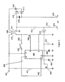
- FIG. 1 is a schematic circuit diagram of high voltage power supply (HVPS) 100 configured to prevent a spark event occurrence in a high voltage device such as electrostatic fluid accelerator.
- HVPS 100 includes a high voltage set-up transformer 106 with primary winding 107 and the secondary winding 108. Primary winding 107 is connected to an a.c. voltage provided by DC voltage source 101 through half-bridge inverter (power transistors 104, 113 and capacitors 105, 114).
- Gate signal controller 111 produces control pulses at the gates of the transistors 104, 113, the frequency of which is determined by the values of resistor 110 and capacitor 116 forming an RC timing circuit.
- HVPS 100 generates a high voltage between terminal 120 and ground that are connected to a HV device or electrodes ( e . g ., corona discharge device).
- An AC component of the voltage applied to the HV device, e . g ., across an array of corona discharge electrodes, is sensed by high voltage capacitor 119 and the sensed voltage is limited by zener diode 122.
- the output voltage exhibits a characteristic voltage fluctuation preceding a spark, the characteristic AC component of the fluctuation leads to a comparatively large signal level across resistor 121, turning on transistor 115.
- Transistor 115 grounds pin 3 of the signal controller 111 and interrupts a voltage across the gates of power transistors 104 and 113. With transistors 104 and 113 rendered nonconductive, an almost instant voltage interruption is affected across the primary winding 107 and, therefore, transmitted to the tightly coupled secondary winding 108. Since a similar rapid voltage drop results at the corona discharge device below a spark onset level, any imminent arcing or dielectrical breakdown is avoided.
- the spark prevention technique includes two steps or stages. First, energy stored in the stray capacitance of the corona discharge device is discharged through the corona current down to the corona onset voltage. This voltage is always well below spark onset voltage. If this discharge happens in time period that is shorter than about 0.1 msec ( i . e ., less than 100 mksec), the voltage drop will efficiently prevent a spark event from occurring. It has been experimentally determined that voltage drops from the higher spark onset voltage level to the corona onset level may preferably be accomplished in about 50 mksec.
- Power supply 100 resumes voltage generation after same predetermined time period defined by resistor 121 and the self-capacitance of the gate-source of transistor 115.
- the predetermined time usually on the order of several milliseconds, has been found to be sufficient for the deionization process and normal operation restoration.
- voltage provided to the corona discharge device rises from approximately the corona onset level to the normal operating level in a matter of several microseconds. With such an arrangement no spark events occur even when output voltage exceeds a value that otherwise causes frequent sparking across the same corona discharge arrangement and configuration.
- Power supply 100 may be built using available electronic components; no special components are required.
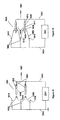
- FIG. 2 is a schematic circuit diagram of an alternative power supply 200 with reed contact 222 and an additional load 223.
- Power supply 200 includes high voltage two winding inductor 209 with primary winding 210 and secondary winding 211.
- Primary winding 210 is connected to ground through power transistor 208 and to a d.c. power source provided at terminal 201.
- PWM controller 205 e . g ., a UC3843 current mode PWM controller
- Secondary winding 211 is connected to a voltage doubler circuit including HV capacitors 215 and 218, and high frequency HV diodes 216 and 217.
- Power supply 200 generates a HV d.c. power of between 10 and 25 kV and typically 18 kV between output terminals 219 and 220 that are connected to a HV device or electrodes (i.e., a load).
- Control transistor 203 turns ON when current through shunt resistor 212 exceeds a preset level and allows a current to flow through control coil 221 of a reed type relay including reed contacts 222.
- Reed relay 203/222 may be a ZP-3 of Ge-Ding Information Inc., Taiwan.
- FIG 3 is a schematic circuit diagram of another HVPS arrangement similar to that shown in Figure 2 .
- HVPS 300 includes reed contact 322 and an additional load 323 connected directly to the output terminals of the HVPS.
- HVPS 300 includes high voltage transformer 309 with primary winding 310 and secondary winding 311.
- Primary winding 310 is connected to ground through power transistor 308 and to a DC source connected to power input terminal 301.
- PWM controller 305 e.g ., a UC3843
- An operating frequency of these control pulses is determined by resistor 302 and the capacitor 304.
- Secondary winding 311 is connected to a voltage doubler circuit that includes HV capacitors 315 and 318 and high frequency HV diodes 316 and 317.
- HVPS 300 generates a high voltage output of approximately 18 kV at output terminals 319 and 320 that are connected to the HV device or electrodes (the load).
- Spark control transistor 303 turns ON when current through the shunt resistor 312 exceeds some predetermined preset level and allows current to flow through control coil 321.
- reed contact 322 closes to shunt the HV output of the HVPS to HV dumping resistor 323, thereby reducing a level of the output voltage for a time period determined by resistor 307 and capacitor 306.
- Use of this incipient spark detection and mitigation arrangement results in virtually no spark production for extended periods of operation.
- FIG 4 shows a power supply configuration similar to that depicted in Figure 2 , HVPS 400 further including relay including normally open contacts 422 and coil 421, and power dumping load 423.
- HVPS 400 includes power transformer 409 with primary winding 410 and the secondary winding 411. Primary winding 410 is connected to ground through power transistor 408 and to a d.c. power source at terminal 401.
- PWM controller 405 e.g ., a UC3843
- Secondary winding 411 is connected to supply a high voltage (e.g., 9 kV) to a voltage doubler circuit that includes HV capacitors 415 and 418, and high frequency HV diodes 416 and 417.
- Power supply 400 generates a high voltage output at terminals 419 and 420 that are connected to the HV device or corona electrodes (load).
- Control transistor 403 turns ON when current through shunt resistor 412 exceeds some preset level predetermined to be characteristic of an incipient spark event, allowing current to flow through coil 421.
- relay contact 422 closes, shortening primary winding 410 through dumping resistor 423.
- the additional load provided by dumping resistor 423 rapidly decreases the output voltage level over some period of time determined by resistor 407 and capacitor 406.
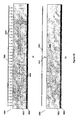
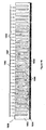
- FIG. 5 is an oscilloscope display including two traces of a power supply output in terms of a corona current 501 and output voltage 502.
- corona current has a characteristic narrow spike 503 indicative of an incipient spark event within a time period of about 0.1 to 1.0 msec, herein shown at about 2.2 msec after the current spike.
- Detection of current spike 503 in corona discharge or similar HV apparatus triggers a control circuit, turns the HVPS OFF and preferably dumps any stored energy necessary to lower an electrode potential to or below a dielectric breakdown safety level.
- steps may be taken to rapidly lower voltage applied to the HV apparatus to a level below a spark initiation or dielectric breakdown potential.
- steps and supportive circuitry may include "dumping" any stored charge into an appropriate "sink", such as a resistor, capacitor, inductor, or some combination thereof.
- the sink may be located within the physical confines of the HVPS and/or at the device being powered, i.e. , the HV apparatus or load.
- the sink may be able to more quickly receive a charge stored within the load, while a sink located at the HVPS may be directed to lower a voltage level of the HVPS output.
- the sink may dissipate power to lower the voltage level supplied to or at the load using, for example, a HV resistor.
- the energy may be stored and reapplied after the spark event has been addressed to rapidly bring the apparatus back up to an optimal operating. Further, it is not necessary to lower the voltage to a zero potential level in all cases, but it may be satisfactory to reduce the voltage level to some value known or predicted to avoid a spark event.
- the HVPS includes processing and memory capabilities to associate characteristics of particular pre-spark indicators (e.g ., current spike intensity, waveform, duration, etc.) with appropriate responses to avoid or minimize, to some preset level, the chance of a spark event.
- the HVPS may be responsive to an absolute amplitude or an area under a current spike ( i.e., ⁇ t ⁇ 1 t ⁇ 2 (i t _ i average )dt ) for selectively inserting a number of loads previously determined to provide a desired amount of spark event control, e . g ., avoid a spark event, delay or reduce an intensity of a spark event, provide a desired number or rate of spark events, etc.
- FIG. 6 is a diagram of HVPS 601 according to the invention connected to supply HV power to an electrostatic device 602, e.g ., a corona discharge fluid accelerator.
- Electrostatic device 602 may include a plurality of corona discharge electrodes 603 connected to HVPS 601 by common connection 604.
- Attractor or collector electrodes 605 are connected to the complementary HV output of HVPS 601 by connection 606.
- respective corona discharge electron clouds are formed in the vicinity of the electrodes, charging the intervening fluid (e.g ., air) molecules acting as a dielectric between corona discharge electrodes 603 and the oppositely charged attractor or collector electrodes 605.
- intervening fluid e.g ., air
- the ionized fluid molecules are accelerated toward the opposite charge of collector/attractor electrodes 605, resulting in a desired fluid movement.
- the dielectric properties of the fluid may vary. This variation may be sufficient such that the dielectric breakdown voltage may be lowered to a point where electrical arcing may occur between sets of corona discharge and attractor electrodes 603, 605. For example, dust, moisture, and/or fluid density changes may lower the dielectric breakdown level to a point below the operating voltage being applied to the device.
- a pre-spark signature event e.g ., a current spike or pulse, etc.
- appropriate steps are implemented to manage the event, such as lowering the operating voltage in those situations wherein it is desirable to avoid a spark.
- a method according to an embodiment of the invention may manage spark events by rapidly changing voltage levels (for example, by changing duty cycle of PWM controller) to make spark discharge more uniform, provide a desired spark intensity and/or rate, or for any other purpose.
- additional applications and implementations of embodiments of the current invention include pre-park detection and rapid voltage change to a particular level so as to achieve a desired result.
- the power supply should be inertialess. That means that the power supply should be capable of rapidly varying an output voltage in less time than a time period between a pre-spark indicator and occurrence of a spark event. That time is usually in a matter of one millisecond or less.
- an efficient and rapid method of pre-spark detection should be incorporated into power supply shut-down circuitry.
- the load device e.g., corona discharge device, should have low self-capacitance capable of being discharged in a time period that is shorter than time period between a pre-spark signature and actual spark events.
- FIG. 7A is a block diagram of a power supply suitable to power a corona discharge device consistent with an embodiment of the invention.
- High voltage power supply (HVPS) 705 generates a power supply voltage 701 ( Figure 7B ) of varying amplitude Vac+dc.
- Voltage 701 has superimposed on an average d.c. voltage of Vdc an a.c. or alternating component of amplitude Vac having an instantaneous value represented by the distance 703 (i.e., an alternating component of the voltage).
- a typical average d.c. component of the voltage 701 (Vdc) is in the range of 10 kV to 25 kV and more preferably equal to 18kV.
- the ripple frequency "f" is typically around 100 kHz.
- low frequency harmonics such as multiples of the 60 Hz commercial power line frequency including 120Hz may be present in the voltage wave-form.
- the following calculation considers only the most significant harmonic, that is the highest harmonic, in this case 100kHz.
- the ripples' peak-to-peak amplitude 703 (Vac being the a.c. component of the voltage 701) may be in the range of 0 to 2000 volts peak-to-peak and, more preferably, less than or equal to 900V, with an RMS value of approximately 640V.
- Voltage 701 is applied to the pair of electrodes (i.e., the corona discharge electrode and the attractor electrode).
- Resistor 706 represents the internal resistance of HVPS 705 and the resistance of the wires that connect HVPS 705 to the electrodes, this resistance typically having a relatively small value.
- Capacitor 707 represents the parasitic capacitance between the two electrodes. Note that the value of capacitor 707 is not constant, but may be roughly estimated at the level of about 10 pF.
- Resistor 708 represents the non-reactive d.c. ohmic load resistance R characteristic of the air gap between the corona discharge and attractor electrodes. This resistance R depends on the voltage applied, typically having a typical value of 10 mega-Ohms.
- the d.c. component from the HVPS 705 flows through resistor 708 while the a.c. component primarily flows through the capacitance 707 representing a substantially lower impedance at the 100 kHz operating range than does resistor 708.
- device 700 may be described with reference to the timing diagram of Figure 7B .
- Imax some maximum amplitude
- ions are emitted from the corona discharge electrode so as to charge ambient molecules and particles of the fluid (i.e., air molecules).
- maximum power is generated and maximum ozone production (in air or oxygen) occurs.
- Imin maximum amplitude
- Acceleration of the ambient fluid results from the moment of ions forming the corona discharge electrodes to the attractor electrode. This is because under the influence of voltage 701, ions are emitted from the corona discharge electrode and create an "ion cloud" surrounding the corona discharge electrode. This ion cloud moves toward the opposite attractor electrode in response to the electric field strength, the intensity of which is proportional to the value of the applied voltage 701.
- the power supplied by power supply 705 is approximately proportional to the output current 702 (assuming voltage 701 is maintained substantially constant).
- the pulsated nature of current 702 results in less energy consumption than a pure d.c. current of the same amplitude.
- Figure 8A shows the corona discharge device that does not satisfy the above equations. It includes corona discharge electrode 800 in the shape of a needle, the sharp geometry of which provides the necessary electric field to produce a corona discharge in the vicinity of the pointed end of the needle.
- the opposing collector electrode 801 is much larger, in the form of a smooth bar.
- High voltage power supply 802 is connected to both of the electrodes through high voltage supply wires 803 and 804.
- this arrangement does not create any significant capacitance between the electrodes 800 and 801. Generally, any capacitance is directly proportional to the effective area facing between the electrodes.
- FIG 8B shows an alternative corona discharge device.
- a plurality of corona discharge electrodes are in the shape of long thin corona discharge wires 805 with opposing collector electrodes 806 in the shape of much thicker bars that are parallel to corona wires 805.
- High voltage power supply 807 is connected to corona discharge wires 805 and collector electrode 806 by respective high voltage supply wires 809 and 810. This arrangement provides much greater area between the electrodes and, therefore creates much greater capacitance therebetween. Therefore, the current flowing from corona wires 805 to collector electrodes 806 will have a significant a.c. component, providing that high voltage power supply 807 has sufficient current supplying capacity.
- Corona discharge devices arrangements like shown in the Figure 8B provide greater air accelerating capacity and comparatively small ozone production when powered by a high voltage power supply with substantial high frequency current ripples but small voltage ripples (i.e., alternating components).
- high voltage power supply circuit 100 may be configured to be capable of generating a high voltage having small high frequency ripples.
- power supply 100 includes high voltage dual-winding transformer 106 with primary winding 107 and secondary winding 108.
- Primary winding 107 is connected to a d.c. voltage source 101 through a half-bridge inverter (power transistors 104, 113 and capacitors 105, 114).
- Gate signal controller 111 produces control pulses at the gates of the transistors 104, 113 through resistors 103 and 117. An operating frequency of these pulses is determined by values selected for resistor 110 and capacitor 116.
- Secondary winding 108 of transformer 106 is connected to bridge voltage rectifier 109 including four high voltage high frequency power diodes. Power supply 100 generates a high voltage output between the terminal 120 and ground which is connected to the electrodes of corona discharge device.
- Figure 9 depicts oscilloscope traces of the output current and voltage waveform, high voltage 901 at the corona discharge device and together with the resultant current 902 produced and flowing through the array of electrode. It can be seen that voltage 901 has a relatively constant amplitude of about 15,300 V with little or no alternating component. Current 902, on the other hand, has a relatively large alternating current component (ripples) in excess of 2mA, far exceeding the current mean value (1.189mA).
- the present invention further includes embodiments in which a low inertia power supply is combined with an array of corona discharge elements presenting a highly reactive load to the power supply. That is, the capacitive loading of the array greatly exceeds any reactive component in the output of the power supply. This relationship provides a constant, low ripple voltage and a high ripple current. The result is on a highly efficient electrostatic fluid accelerator with reduced ozone production.
- FIG. 10A is a schematic diagram of an Electrostatic Fluid Accelerator (EFA) device 1000 according to another embodiment of the invention comprising two EFA stages 1014 and 1015.
- First EFA stage 1014 includes corona discharge electrode 106 and associated accelerating electrode 1012;
- second EFA stage 1015 includes corona discharge electrode 1013 and associated accelerating electrode 1011. Both EFA stages and all the electrodes are shown schematically. Only one set of corona discharge and collecting electrodes are shown per stage for ease of illustration, although it is expected that each stage may include a large number of arrayed pairs of corona and accelerating electrodes.
- EFA 1000 An important feature of EFA 1000 is that the distance d 1 between the corona discharge electrode 1006 and collector electrode 1012 is comparable to the distance d 2 between collector electrode 1012 and the corona discharge electrode 1013 of the subsequent stage 1015, i.e., the closest distance between elements of adjacent stages is not much greater than the distance between electrodes within the same stage.
- the inter-stage distance d 2 between collector electrode 1012 and corona discharge electrode 1013 of the adjacent stage should be between 1.2 and 2.0 times that of the intra-stage spacing distance d 1 between corona discharge electrode 1006 and collector electrode 1012 (or spacing between corona discharge electrode 1013, and collector electrode 1011) within the same stage.
- capacitance between electrodes 1006 and 1012 and between 1006 and 1013 are of the same order.
- the capacitance coupling between corona discharge electrodes 1006 and 1013 may allow some parasitic current to flow between the electrodes.
- This parasitic current is of the same order of amplitude as a capacitive current between electrode pair 1006 and 1012.
- each should be supplied with synchronized high voltage waveforms.
- both EFA stages are powered by a common power supply 1005 i.e., a power supply having a single voltage conversion circuit (e.g., power transformer, rectifier, and filtering circuits, etc.) feeding both stages in parallel. This ensures that the voltage difference between electrodes 1006 and 1013 is maintained constant relative to electrodes 1006 and 1011 so that no or only a very small current flows between electrodes 1006 and 1013.
- Figure 10B shows an alternate configuration of an EFA 1001 including a pair of EFA stages 1016 and 1017 powered by separate power supplies 1002 and 1003, respectively.
- First EFA stage 1016 includes corona discharge electrode 1007 and collecting electrode 1008 forming a pair of complementary electrodes within stage 1016.
- Second EFA stage 1017 includes corona discharge electrode 1009 and collecting electrode 1010 forming a second pair of complementary electrodes. Both EFA stage 1016, 1017 and all electrodes 1007-1010 are shown schematically.
- First EFA stage 1016 is powered by power supply 1002 and second EFA stage 1017 is powered by power supply 1003. Both EFA stages as well as both power supplies 1002 and 1003 may be of the same design to simplify synchronization, although different designs may be used as appropriate to accommodate alternative arrangements. Power supplies 1002 and 1003 are synchronized by the control circuitry 1004 to provide synchronized power outputs. Control circuitry ensures that both power supplies 1002 and 1003 generate synchronized and syn-phased output voltages that are substantially equal such that the potential difference between the electrodes 1007 and 1009 is maintained substantially constant (e.g., has no or very small a.c. voltage component).
- voltage V1 present on electrode 1007 ( Figure 10B ) and voltage V2 present on electrode 1009 are synchronized and syn-phased, but not necessarily equal in d.c. amplitude. Because of complete synchronization, the difference V1 ⁇ V2 between the voltages present on electrodes 1007 and 1009 is near constant representing only a d.c. offset value between the signals (i.e., no a.c. component).
- the closest spacing of electrodes of adjacent EFA stages may be approximated as follows. Note that a typical EFA operates efficiently over a rather narrow voltage range.
- the voltage V c applied between the corona discharge and collecting electrodes of the same stage should exceed the so called corona onset voltage V onset for proper operation. That is, when voltage V c is less than V onset , no corona discharge occurs and no air movement is generated. At the same time V c should not exceed the dielectric breakdown voltage V b so as to avoid arcing.
- V b may be more than twice as much as V onset .
- the V b /V onset ratio is about 1.4 ⁇ 1.8 such that any particular corona discharge electrode should not be situated at a distance from a neighboring collecting electrode where it may generate a "back corona.” Therefore, the normalized distance aNn between closest electrodes of neighboring stages should be at least 1.2 times greater than the normalized distance "aNc" between the corona discharge and the collecting electrodes of the same stage and preferably not more than 2 times greater than distance "aNc.” That is, electrodes of neighboring stages should be spaced so as to ensure that a voltage difference between the electrodes is less than the corona onset voltage between any electrodes of the neighboring stages.
- a two stage EFA 1200 includes a pair of HVPSs 1201 and 1202 associated with respective first and second stages 1212 and 1213. Both stages are substantially identical and are supplied with electrical power by identical HVPSs 1201 and 1202.
- HVPSs 1201 and 1202 include respective pulse width modulation (PWM) controllers 1204 and 1205, power transistors 1206 and 1207, high voltage inductors 1208 and 1209 (i.e., filtering chokes) and voltage doublers 1201 and 1202.
- PWM pulse width modulation
- HVPSs 1220 and 1221 provide power to respective EFA corona discharge electrodes of stages 1212 and 1213.
- EFA electrodes of stages 1212 and 1213 are diagrammatically depicted as single pairs of one corona discharge electrode and one accelerator (or attractor) electrode, each stage would typically include multiple pairs of electrodes configured in a two-dimensional array.
- PWM controllers 1204, 1205 generate (and provide at pin 7) high frequency pulses to the gates of respective power transistors 1206 and 1207.
- the frequency of these pulses is determined by respective RC timing circuits including resistor 1216 and capacitor 1217, and resistor 1218 and the capacitor 1219.
- RC timing circuits including resistor 1216 and capacitor 1217, and resistor 1218 and the capacitor 1219.
- controller 1205 is connected to receive a synchronization signal pulse from pin 1 of the PWM controller 1204 via a synchronization input circuit including resistor 1215 and capacitor 1214. This arrangement synchronizes PWM controller 1205 to PWM controller 1204 so that both PWM controllers output voltage pulses that are both synchronous (same frequency) and syn-phased (same phase).
- first EFA device 1311 consists of two serial or tandem stages 1314 and 1315.
- First stage 1314 contains a plurality of parallel corona discharge electrodes 1301 aligned in a first vertical column and collecting electrodes 1302 aligned in a second columns parallel to the column of corona discharge electrodes 1301. All the electrodes are shown in cross-section longitudinally extending in to and out from the page.
- Corona discharge electrodes 1301 may be in the form of conductive wires as illustrated, although other configurations may be used.
- Collecting electrodes 1302 are shown horizontally elongate as conductive bars.
- Second stage 1315 similarly contains a column of aligned corona discharge electrodes 1303 (also shown as thin conductive wires extending perpendicular to the page) and collecting electrodes 1304 (again as bars). All the electrodes are mounted within air duct 1305.
- First and second stages 1314 and 1315 of EFA 1311 are powered by respective separate HVPSs (not shown). The HVPSs are synchronized and syn-phased so the corona discharge electrodes 1303 of second stage 1315 may be placed at the closest possible normalized distance to collecting electrodes 1302 of first stage 1314 without adversely interacting and degrading EPA performance.
- a normalized distance 1310 between corona discharge electrodes 1301 and the leading edges of the closest vertically adjacent collecting electrodes 1302 is equal to aN1.
- Normalized distance aN2 (1313) between corona electrodes 1303 of the second stage and the trailing edges of collecting electrodes 1302 of the first stage should be some distance aN2 greater that aN1, the actual distance depending of the specific voltage applied to the corona discharge electrodes.
- aN2 should be just greater than aN1, i.e., be within a range of 1 to 2 times distance aN1 and, more preferably, 1.1 to 1.65 times aN1 and even more preferably approximately 1.4 times aN1.
- distance aN2 should be just greater than necessary to avoid a voltage between the corona onset voltage creating a current flow therebetween.
- this normalized "stant" distance aN2 is equal to 1.4 x aN1.
- the horizontal distance 1312 between neighboring stages is less than distance aN2 (1313).
- intra-stage spacing is minimized when the same type of the electrodes of the neighboring stages are located in one plane 1320 (as shown in Figure 13A ).
- Plane 1314 may be defined as a plane orthogonal to the plane containing the edges of the corona discharge electrodes (plane 1317 in Figure 13A ).
- the resultant minimal spacing distance between electrodes of adjacent EFA stages is equal to aN2 as shown by line 1319. Note that the length of line 1319 is the same as distance 1313 (aN2) and is greater than distance 1312 so that inter-stage spacing is increased.
- FIG 14 is a schematic diagram of EFA device 1400 including wire-like corona electrodes 1402 (three are shown for purposes of the present example although other numbers may be included, a typical device having ten or hundreds of electrodes in appropriate arrays to provide a desired performance) and accelerating electrodes 1409 (two in the present simplified example).
- Each of the accelerating electrodes 1409 includes a relatively high resistance portion 1403 and a low resistance portion 1408.
- High resistance portion portions 1403 have a specific resistivity p within a range of 10 1 to 10 9 ' ⁇ -cm and, more preferably, between 10 5 and 10 8 ' ⁇ -cm with a more preferred range between 10 6 and 10 7 ' ⁇ -cm.
- corona electrodes 1402 are in the form or shape of thin wires, while accelerating electrodes 1409 are in the shape of bars or plates. "Downstream" portions of corona electrodes 1402 closest to accelerating electrodes 1409 form ionizing edges 1410. Corona electrodes 1402 as well as low resistance portion 1408 of accelerating electrodes 1409 are connected to opposite polarity terminals of high voltage power supply (HVPS) 1401 via wire conductors 1404 and 1405.
- High voltage power supply (HVPS) 1401 high voltage power supply
- Low resistance portion 1408 has a specific resistivity ⁇ ⁇ 10 4 ⁇ -cm and preferably, no greater than 1 ⁇ -cm and, even more preferably, no greater than 0.1 ⁇ -cm.
- EFA 1400 produces a fluid flow in a desired fluid flow direction shown by the arrow 1407.
- HVPS 1401 is configured to generate a predetermined voltage between electrodes 1402 and collecting electrodes 1409 such that an electric field is formed in-between the electrodes. This electric field is represented by the dotted flux lines schematically shown as 1406.
- corona onset voltage When the voltage exceeds a so-called “corona onset voltage,” a corona discharge activity is initiated in the vicinity of corona electrodes 1402, resulting in a corresponding ion emission process from corona electrodes 1402.
- the corona discharge process causes fluid ions to be emitted from corona electrodes 1402 and accelerated toward accelerating electrodes 1409 along and following the electric field lines 1406.
- the corona current in the form of free ions and other charged particulates, approaches the closest ends of accelerating electrodes 1409.
- the corona current then flows along the path of lowest electrical resistance through the electrodes as opposed to some high resistance path of the surrounding fluid. Since high resistance portion 1403 of accelerating electrodes 1409 has a lower resistance that the surrounding ionized fluid, a significant portion of the corona current flows through the body of the accelerating electrodes 1409, i.e., through high resistance portion 1403 to low resistance portion 1408, the return path to HVPS 1401 completed via connecting wire 1405.
- corona current is non-linearly proportional to the voltage V a between corona electrodes 1402 and the ends of accelerating electrodes 1409, i.e., current increases more rapidly than does voltage.
- the corona discharge process is considered “irregular” by nature (i.e. , “unpredictable”), the corona current value depending on multiple environmental factors subject to change, such as temperature, contamination, moisture, foreign objects, etc. If for some reason the corona current becomes greater at one location of an inter-electrode space than at some other location, a voltage drop V d along the corresponding high resistance portion 1403 will be greater and therefore actual voltage V a at this location will be lower. This, in turn, limits the corona current at this location and prevents or minimizes sparking or arcing onset.
- a corona onset voltage is assumed to be equal to 8.6kV to achieve a minimum electric field strength of 30kV/cm in the vicinity of the corona electrodes 1402. This value may be determined by calculation, measurement, or otherwise and is typical of a corona onset value for a corona/accelerating electrode spacing of 10 mm and a corona electrode diameter of 0.1 mm.
- the total resistance R total of high resistance portion 103 for of accelerating electrodes 1409 is equal to 0.5 M ⁇ while the width of high resistance portion 1403 along airflow direction 1407 (see Figure 14 ) is equal to 1 inch.
- Empirical coefficient k l for this particular design is equal to 22 * 10 -6 .
- V a 12.5 kV
- This "negative feedback" effect thereby operates to restore normal EFA operation even in the event of some local irregularities.
- the maximum current through the circuit is effectively limited by the resistance of the local area at which the foreign object contacts the electrodes.
- the short circuit current would be limited only by the maximum power (i.e., maximum current capability) ofHVPS 1401 and/or by any energy stored in its output filter (e.g., filter capacitor) and thereby present a significant shock hazard to a user, produce an unpleasant "snapping" or "popping" sound caused by sparking and/or generate electromagnetic disturbances (e.g., radio frequency interference or rfi).
- maximum power i.e., maximum current capability
- filter capacitor e.g., filter capacitor
- the specific resistance characteristics and geometry (length versus width ratio) of high resistivity portion 103 is selected to provide trouble-free operation while not imposing current limits on EFA operation. This is achieved by providing a comparatively large ratio (preferably if at least ten) between (i) the total length of the accelerating electrode (size transverse to the main fluid flow direction) and (ii) accelerating electrode to its width (size along with fluid flow direction). Generally the length of an electrode should be greater than a width of that electrode.
- Optimal results may be achieved by providing multiple accelerating electrodes and preferably a number of accelerating electrodes equal to within plus or minus one of the number of corona electrodes, depending on the location and configuration of the electrodes. Note that while Figure 14 shows two accelerating electrodes and three corona electrodes for purposes of illustration, other electrode configurations might well include three of four accelerating electrodes facing the same three corona electrodes, or comprise other numbers and configurations of alternative electrode configurations.
- the HVPS may be equipped with a current sensor or other device capable of detecting such an overcurrent event and promptly interrupting power generation or otherwise inhibiting current flow. After a predetermined reset or rest period of time T off, power generation may be restored for some minimum predetermined time period T on sufficient for detection of any remaining or residual short circuit condition. If the short circuit condition persists, the HVPS may be shut down or otherwise disabled, again for at least the time period T off .
- HVPS 1401 may continue this on-off cycling operation for some number of cycles with To ff substantially greater (e.g., ten times or longer) than T on . Note that, in certain cases, the cycling will have the effect of clearing certain shorting conditions without requiring manual intervention.
- FIG. 15 depicts another embodiment of an EFA with accelerating electrodes having high resistivity portions.
- EFA 1400 shown in the Figure 14 and EFA 1500 The primary distinction between EFA 1400 shown in the Figure 14 and EFA 1500 is that, in the latter, low resistivity portions 1508 are completely contained within high resistivity portions 1503 of accelerating electrodes 1509 (i.e., are fully encapsulated by the surrounding high resistivity material).
- This modification provides at least two advantages to this embodiment of the invention.
- fully encapsulating low resistivity portions 1508 within high resistivity portion 1503 enhances safety of the EFA by preventing unintentional or accidental direct contact with the high voltage "hot" terminals of HVPS 1501.
- the configuration forces the corona current to flow through a greater portion or volume of high resistivity portion 1503 instead of merely a surface region.
- the EFA has an inherent ability to collect particles present in a fluid at the surface of the accelerating electrodes. When some amount or quantity of particles is collected or otherwise accumulate on the accelerating electrodes, the particles may cover the surface of the electrode with a contiguous solid layer of contaminants, e.g., a continuous film. The electrical conductivity of this layer of contaminants may be higher that of the conductivity of the high resistivity material itself. In such a case, the corona current may flow through this contaminant layer and compromise the advantages provided by the high resistivity material. EFA 1500 of Figure 15 avoids this problem by fully encapsulating low resistivity portion 1508 within high resistivity portion 1503.
- low resistivity portion 1508 need not be continuous or have any point in direct contact with the supply terminals of HVPS 1501 or conductive wire 1505 providing power from HVPS 1501. Is should be appreciated that a primary function of these conductive parts is to counterpoise the electric potential along the length of the accelerating electrodes 1509, i.e., distribute the current so that high resistivity portion 1503 in contact with low resistivity portion 1508 are maintained at some equipotential.
- corona electrodes 1502 are grounded, there is a substantially reduced or nonexistent opportunity for inadvertent or accidental exposure to dangerous current levels that may result in injury and/or electrocution by high operating voltages, this because there is no "hot" potential to touch throughout the structure.
- FIG 16 is a schematic diagram of an EFA assembly 1600 with corona electrodes 1602 (preferably formed as longitudinally oriented wires having ionizing edges 1610) and accelerating electrodes 1603 consisting of a plurality of horizontally stacked high resistivity bars each with a different resistivity value decreasing along the width of the accelerating electrode.
- Accelerating electrodes 1603 are made of several segments 1608 through 1612 each in intimate contact with its immediately adjacent neighbor(s). Each of these segments is made of a material or otherwise engineered to have a different specific resistivity value ⁇ n .
- accelerator electrodes 1603 are depicted for purposes of illustration as comprising a number of discrete segments of respective resistivity values ⁇ n , resistivity values may be made to continuously vary over the width of the electrode. Gradual resistivity variation over the width may be achieved by a number of processes including, for example, ion implantation of suitable impurity materials at appropriately varying concentration levels to achieve a gradual increase or decrease in resistivity.
- Figure 17A and 17B are schematic diagrams of still another embodiment of an EFA 1700 in which accelerating electrodes 1703 are made of a high resistivity material. While, for illustrative purposes, Figures 17A and 17B depict a particular number of corona electrodes 1702 and accelerating electrodes 1703, respectively, other numbers and configurations may be employed consistent with various embodiments of the invention.
- Accelerating electrodes 1703 are made of thin strips or layers of one or more high resistivity materials.
- Corona electrodes 1702 are made of a low resistivity material such as metal or a conductive ceramic.
- HVPS 1701 is connected to corona electrodes 1702 and accelerating electrodes 1703 by conducting wires 1704 and 1705.
- the geometry of corona electrodes 1702 is in contrast to geometries wherein the electrodes are formed as needles or thin wires which are inherently more difficult to maintain and install and are subject to damage during the course of normal operation of the EFA.
- a downstream edge of each corona electrode 1702 includes an ionizing edge 1710.
- the thin wire typically used for corona electrodes is fragile and therefore not reliable.
- the present embodiment depicted in Figures 17A and 17B provides corona electrodes in the shape of relatively wide metallic strips. While these metal strips are necessarily thin at a corona discharge end so as to readily generate a corona discharge along a "downwind" edge thereof, the strips are relatively wide (in a direction along the airflow direction) and thereby less fragile than a correspondingly thin wire.
- EFA 1700 as depicted in Figure 17A includes accelerating electrodes 1703 that are substantially thinner than those used in prior systems. That is, prior accelerating electrodes are typically much thicker than the associated corona electrodes to avoid generation of an electric field around and about the edges of the accelerating electrodes.
- the configuration shown in Figure 17A minimizes or eliminates any electric field generation by accelerating electrodes 1703 by placement of the edges of corona electrodes 1702 (in the present illustration, the right "downwind" edges of the corona electrodes) counter or opposite to the flat surfaces of the accelerating electrodes 1703.
- At least a portion of the main body of corona electrodes 1702 extends downwind in a direction of desired fluid flow past a leading edge of accelerating electrodes 1703 whereby an operative portion of corona electrodes 1702 along a trailing edge thereof generates a corona discharge between and proximate the extended flat surfaces of accelerating electrodes 1703.
- This orientation and configuration provides an electric field strength in the vicinity of such flat surfaces that is substantially lower than the corresponding electric field strength formed about the trailing edge of corona electrodes 1702.
- a corona discharge is produced in the vicinity of the trailing edge of corona electrodes 1702 and not at the surface of accelerating electrodes 1703.
- a corona current flows through the fluid to be accelerated (e.g., air, insulating liquid, etc.) located between corona electrodes 1702 and accelerating electrodes 1703 by the generation of ions and charged particles within the fluid and transfer of such charges along the body of accelerating electrodes 1703 to HVPS 1701 via conductive wire 1705. Since no current flows in the opposite direction (i.e., from accelerating electrodes 1703 through the fluid to corona electrodes 1702), no back corona is produced. It has been further found that this configuration results in an electric field (represented by lines 1706) that is substantially more linear with respect to a direction of the desired fluid flow (shown by arrow 1707) than might otherwise be provided.
- an electric field represented by lines 1706
- the enhanced linearity of the electric field is caused by the voltage drop across accelerating electrodes 1703 generating equipotential lines of the electric field that are transverse to the primary direction of fluid flow. Since the electric field lines are orthogonal to such equipotential lines, the electric field lines are more parallel to the direction of primary fluid low.
- EFA 1700 as shown in the Figure 17A is provided by isolation of the active portions (i.e., right edges as depicted in the figure) of corona electrodes 1702 from each other by the intervening structure of accelerating electrodes 1703.
- the corona electrodes "do not see” each other and therefore, in contrast to prior systems, corona electrodes 1702 may be positioned in close proximity to one another (that is, in the vertical direction as depicted in Figure 17A ).
- two major obstacles to achieving substantial and greater fluid flows are avoided.
- a first of these obstacles is the high air resistance caused by the relatively thick fronted portions of typical accelerating electrodes.
- the present configuration provides for both corona and accelerating electrodes that have low drag geometries, that is, formed in aerodynamically "friendly" shapes.
- these geometries provide a coefficient of drag Cd for air that is no greater than 1, preferably less than 0.1 and more preferably less than 0.01.
- the actual geometry or shape is necessarily dependent on the desired fluid flow and viscosity of the fluid to be accelerated these factors varying between designs.
- a second obstacle overcome by the present embodiment of the invention is the resultant low density of electrodes possible due to conventional inter-electrode spacing requirements necessary according to and observed by prior configurations.
- U.S. Patent No. 4,812,711 depicts four corona electrodes spaced apart from each other by a distance of 50mm.
- this relatively low density and small number of electrodes can accommodate only very low power levels with a resultant low level of fluid flow.
- the present embodiments accommodate corona to attractor spacing of less than 10mm and preferably less than 1mm.
- FIG. 17B Still another configuration of electrodes is shown in connection with the EFA 1700 of Figure 17B .
- corona electrodes 1702 are placed a predetermined distance from accelerating electrodes 1703 in a direction of the desired fluid flow as shown in arrow 1707.
- the resultant electric field is substantially linear as depicted by the dashed lines emanating from corona electrodes 1702 and directed to accelerating electrodes 1703. Note however, that with respect to the direction of the desired fluid flow, corona electrode 1702 are not placed "in between" accelerating electrodes 1703.
- An object of various embodiments of the present invention as depicted in Figure 17A is directed to achieve closer spacing of corona electrodes (i.e., a higher density of electrodes) consistent with current manufacturing technology than otherwise possible or implemented by other EFA devices. That is, extremely thin and short electrodes may be readily manufactured by a single manufacturing process or step consistent with, for example modem micro-electro-mechanical systems (MEMS) and related semiconductor technologies and capabilities.
- MEMS micro-electro-mechanical systems
- adjacent corona electrodes 1702 may be vertically spaced apart by a distance less than 1mm or even only several ⁇ m from each other. The resultant increase in electrode density provides enhanced fluid acceleration and flow rates.
- 4,812,711 describes a device capable of producing an air velocity of only 0.5 meters per second (m/sec). If, instead, the electrodes are spaced 1mm apart, a 50 fold increase in electrode density and enhanced power capabilities may be achieved to provide a corresponding increase in air velocity, i.e., to about 25 m/sec or 5,000 ft/min. Further, several EFA stages may be placed in succession or tandem in a horizontal direction of desired fluid flow, each stage further accelerating the fluid as it passes through the successive stages. Each of the stages are located a predetermined distance from immediately adjacent stages, this distance determined by the maximum voltage applied to the opposing electrodes of each stage.
- the advantages achieved by various embodiments of the invention are attributable at least in part to use of a high resistivity material as part of the accelerating electrodes.
- the high resistivity material may comprise a relatively high resistance material, such as carbon filled plastic or rubber, silicon, germanium, tin, gallium arsenide, indium phosphide, boron nitride, silicon carbide, cadmium selenide, etc. These materials should have a specific resistivity ⁇ in the range of 10 1 to 10 10 ⁇ -cm and, more preferably, between 10 4 to 10 9 ⁇ -cm with a more preferred range between 10 6 and 10 7 ⁇ -cm.
- Use of the high resistivity material supports enhanced electrode densities.
- corona discharge events take place at or along the trailing or right edges of corona electrodes 1702 but not along the leading or left edges of accelerating electrodes 1703. This is because of the voltage and electric field distribution produced by the corona discharge process.
- the left edges of accelerating electrodes 1703 are at least somewhat thicker than are the right edges of corona electrodes 1702, which are either thin or sharpened.
- the electric field near an electrode is approximately proportional to a thickness of the electrode, the corona discharge starts at the trailing edge of corona electrodes 1702.
- the resultant corona current then flows from the trailing edges of corona electrodes 1702 to the high voltage terminal of HVPS 1701 through two paths.
- a first path is through ionized portions of the fluid along the electric field depicted by lines 1706.
- a second path is through the body of accelerating electrodes 1703.
- the corona current, flowing through the body of accelerating electrodes 1703 results in a voltage drop along this body. This voltage drop progresses from the high voltage terminal as applied to the right edge of accelerating electrodes 1703 toward the left edge of the electrode. As the corona current increases, a corresponding increase is exhibited in this voltage drop.
- the output voltage of HVPS 1701 reaches a level sufficient to initiate corona discharge along the left edge of accelerating electrodes 1703, the voltage drop at these edges is sufficiently high to dampen any voltage increase and prevent a corona discharge along the edge of the accelerating electrodes.
- FIG. 1 A corona discharge condition may be initiated by relatively low voltages, the corona discharge being caused, not by the voltage itself, but by the high-intensity electric field generated by the voltage.
- This electric field strength is approximately proportional to the voltage applied and inversely proportional to the distance between the opposing electrodes. For example, a voltage of about 8kV is sufficient to initiate a corona discharge with an inter-electrode spacing of approximately 1cm. Decreasing the inter-electrode spacing by a factor of ten to 1mm reduces the voltage required for corona discharge initiation to approximately 800V.
- inter-electrode spacing reduces the required corona initiation voltage to 80V, while 10micron spacing requires only 8V to initiate a corona discharge.
- These lower voltages provide for closer inter-electrode spacing and spacing between each stage, thereby increasing total fluid acceleration several fold. As previously described, the increase is approximately inversely proportional to the square of the distance between the electrodes resulting in an overall increases of 100, 10,000 and 1,000,000 in air flow, respectively compared to a 1cm spacing.
- EFA 1800 includes corona electrode 1802 and accelerating electrode 1803. Accelerating electrode 1803 in turn, includes a low resistivity portion 1804 and a high resistivity portion 1806.
- a corona current flows through an ionized fluid present between corona electrode 1802 and accelerating electrode 503 (i.e., through the inter-electrode space) over a current path indicated by arrows 1805, the path continuing through.high resistivity portion 1806 of accelerating electrode 1803 as indicated by the arrows.
- a resultant discharge current is directed through a narrow path depicted by arrow 1807 of Figure 18B .
- the current then proceeds along a wider path 1808 across high resistivity portion 1806.
- the increase current flow emanates from a small region of acceleration electrode 1803, only gradually expanding outwardly over path 1808, the resulting resistance over path 1808 is substantially higher than when such current is distributed over the entirety of high resistivity portion 1806.
- the spark or a pre-spark event signaled by an increased current flow is limited by the resistance along path 1808 thereby limiting the current. If high resistivity portion 1806 is selected to have a specific resistance and width to length ratio, any significant current increase can be avoided or mitigated.
- Such current increases may be caused by a number of events including the aforementioned electrical discharge or spark, presence of a foreign object (e.g., dust, insect, etc.) on or between the electrodes, screwdriver, or even a finger placed between and coming into contact with the electrodes.
- a foreign object e.g., dust, insect, etc.
- EFA 1900 includes a comb-like high resistivity portion 1906 of accelerating electrode 1903. Any localized event such as a spark clearly is restricted to flow over a small portion of attracting electrode 1903 such as over a single or a small number of teeth near the event.
- a corona current associated with a normal operating condition is shown by arrows 1905.
- an event such as a spark shown at arrows 1907 and 1908 is limited to flowing along finger or tooth 1906.
- the resistance over this path is sufficiently high to moderate any increase in current caused by the event.
- performance is enhanced with increasing number of teeth rather than a selection of a width to length ratio.
- a typical width to length ratio of 1 to 0.1 may be appropriate with a more preferred ratio of 0.05 to 1 or less.
- various features of the present invention make it possible to use materials other than solids for producing a corona discharge or emission of ions.
- solid materials only "reluctantly" give up and produce ions thereby limiting EFA acceleration of a fluid.
- many fluids, such as water may release more ions if positioned and shaped to produce a corona discharge.
- a conductive fluid as a corona emitting material is described in U.S. Patent No. 3,751,715 .
- a teardrop shaped container is described as a trough for containing a conductive fluid.
- the conductive fluid may be, for example, tap water or more preferably, an aqueous solution including a strong electrolyte such as NaCl, HNO3, NaOH, etc.
- Figure 20 shows the operation of an EFA according to an embodiment of the present invention in which EFA 2000 includes five accelerating electrodes 2003 and four corona electrodes 2002. All of these electrodes are shown in cross section.
- the corona electrodes each consist of narrow elongate non-conductive shells 2009 made of an insulating material such as plastic or silicon with slots 2011 formed at ionizing edge 2010 in the trailing edge or right sides of the shells.
- the shells 2009 of corona electrodes 2002 are connected to a conductive fluid supply or reservoir, not shown, via an appropriate supply tube.
- Slots 2011 formed in the trailing edge of corona electrodes 2002 are sufficiently narrow so that fluid is contained within shells 2009 by fluid molecular tension. Slots 2011 may be equipped with sponge-like "stoppages" or nozzle portions to provide a constant, slow release of conductive fluid through the slot.
- HVPS 2001 generates a voltage sufficient to produce a corona discharge such that conductive fluid 2008 acts as a sharp-edged conductor and emits ions from the trailing edge of corona electrode 2002 at slots 2011. Resultant ions of conductive fluid 2008 migrate from slot 2011 toward accelerating high resistivity electrodes 2003 along an electric field represented by lines 2006. As fluid is consumed in production of the corona discharge, the fluid is replenished via shells 2009 from an appropriate fluid supply or reservoir (not shown).
Description
- The invention relates to a method and device for the corona discharge generation and in particular to method of and devices for fluid acceleration to provide velocity and momentum to a fluids, especially to air, through the use of ions and electrical fields for the movement and control of such fluids.
- A number of patents (see, e.g., United States Patent Nos.
4,210,847 of Shannon et al. and4,231,766 of Spurgin ) have recognized the fact that corona discharge may be used for generating ions and charging particles. Such methods are widely used in electrostatic precipitators and electric wind machines as described in Applied Electrostatic Precipitation published by Chapman & Hall (1997). The corona discharge device may be generated by application of a high voltage to pairs of electrodes, e.g., a corona discharge electrode and an attractor electrode. Therein a corona discharge is generated by application of a high voltage power source to pairs of electrodes. The electrodes are configured and arranged to generate a noun-uniform electric field proxite one of the electrodes (called a corona discharge electrode) so as to generate a corona and a resultant corona current toward a nearby complementary electrode (called a collector or attractor electrode). The requisite corona discharge electrode geometry typically requires a sharp point or edge directed toward the direction of corona current flow, i.e., facing the collector or attractor electrode. - Thus at least the corona discharge electrode should be small or include sharp points or edges to generate the required electric field gradient in the vicinity of the electrode. The corona discharge takes place in the comparatively narrow voltage range between a lower corona onset voltage and a higher breakdown (or spark) voltage. Below the corona onset voltage, no ions are emitted from the corona discharge electrodes and, therefore, no air acceleration is generated. If, on the other hand, the applied voltage approaches a dielectric breakdown or spark level, sparks and electric arcs may result that interrupt the corona discharge process and create unpleasant electrical arcing sounds. Thus, it is generally advantageous to maintain high voltage between these values and, more especially, near but slightly below the spark level where fluid acceleration is most efficient.
- There are a number of patents that address the problem of sparking in electrostatic devices. For instance,
US Patent No. 4,061,961 of Baker describes a circuit for controlling the duty cycle of a two-stage electrostatic precipitator power supply. The circuit includes a switching device connected in series with the primary winding of the power supply transformer and a circuit operable for controlling the switching device. A capacitive network, adapted to monitor the current in the primary winding of the power supply transformer, is provided for operating the control circuit. Under normal operating conditions, i.e., when the current in the primary winding of the power supply transformer is within nominal limits, the capacitive network operates the control circuit to allow current to flow through the power supply transformer primary winding. However, upon sensing an increased primary current level associated with a high voltage transient generated by arcing between components of the precipitator and reflected from the secondary winding of the power supply transformer to the primary winding thereof, the capacitive network operates the control circuit. In response, the control circuit causes the switching device to inhibit current flow through the primary winding of the transformer until the arcing condition associated with the high voltage transient is extinguished or otherwise suppressed. Following some time interval after termination of the high voltage transient, the switching device automatically re-establishes power supply to the primary winding thereby resuming normal operation of the electrostatic precipitator power supply. -
US Patent No. 4,156,885 of Baker et al. , describes an automatic current overload protection circuit for electrostatic precipitator power supplies operable after a sustained overload is detected. -
US Patent No. 4,335,414 of Weber describes an automatic electronic reset current cut-off for an electrostatic precipitator air cleaner power supply. A protection circuit protects power supplies utilizing a ferroresonant transformer having a primary power winding, a secondary winding providing relatively high voltage and a tertiary winding providing a relatively low voltage. The protection circuit operates to inhibit power supply operation in the event of an overload in an ionizer or collector cell by sensing a voltage derived from the high voltage and comparing the sense voltage with a fixed reference. When the sense voltage falls below a predetermined value, current flow through the transformer primary is inhibited for a predetermined time period. Current flow is automatically reinstated and the circuit will cyclically cause the power supply to shut down until the fault has cleared. The reference voltage is derived from the tertiary winding voltage resulting in increased sensitivity of the circuit to short duration overload conditions. - As recognized by the prior art, any high voltage application assumes a risk of electrical discharge. For some applications a discharge is desirable. For many other high voltage applications a spark is an undesirable event that should be avoided or prevented. This is especially true for the applications where high voltage is maintained at close to a spark level i.e., dielectric breakdown voltage. Electrostatic precipitators, for instance, operate with the highest voltage level possible so that sparks are inevitably generated. Electrostatic precipitators typically maintain a spark-rate of 50-100 sparks per minute. When a spark occurs, the power supply output usually drops to zero volts and only resumes operation after lapse of a predetermined period of time called the "deionization time" during which the air discharges and a pre-spark resistance is reestablished. Each spark event decreases the overall efficiency of the high voltage device and is one of the leading reasons for electrode deterioration and aging. Spark generation also produces an unpleasant sound that is not acceptable in many environments and associated applications, like home-use electrostatic air accelerators, filters and appliances.
- In addition to the unwanted noise created by sparking, other inefficiencies plague the prior art. For example, pairs of corona discharge and attractor electrodes should be configured and arranged to produce a non-uniform electric field generation, at least one electrode, i.e., the corona discharge electrode, often being relatively small and/or including sharp points or edges to provide a suitable electric field gradient in the vicinity of the electrode. There are several known configurations used to apply voltage between the electrodes to efficiently generate the requisite electric field for ion production.
U.S. Patent No. 4,789,801 of Lee and Patent Nos.6,152,146 and6,176,977 of Taylor, et al. , describe applying a pulsed voltage waveform across pairs of the electrodes, the waveform having a duty cycle between 10% and 100%. These patents describe that such voltage generation decreases ozone generation by the resultant corona discharge device in comparison to application of a steady-state, D.C. power. Regardless of actual benefit of such voltage generation for reducing ozone production, air flow generation is substantially decreased by using a duty cycle less than 100%, while the resultant pulsating air flow is considered unpleasant. -
U.S. Patent No. 6,200,539 of Sherman, et al. describes use of a high frequency high voltage power supply to generate an alternating voltage with a frequency of about 20 kHz. Such high frequency high voltage generation requires a bulky, relatively expensive power supply typically incurring high energy losses.U.S. Patent No. 5,814,135 of Weinberg describes a high voltage power supply that generates very narrow (i.e., steep, short duration) voltage pulses. Such voltage generation can generate only relatively low volume and rate air flow and is not suitable for the acceleration or movement of high air flows. -
U.S. Patent Nos. 4,789,801 of Lee ,5,667,564 of Weinberg ,6,176,977 of Taylor, et al. , and4,643,745 of Sakakibara , et al. also describe air movement devices that accelerate air using an electrostatic field. Air velocity achieved in these devices is very low and is not practical for commercial or industrial applications. - [0005]
U.S. Patent Nos. 3,699,387 and3,751,715 of Edwards describe the use of multiple stages of Electrostatic Air Accelerators (EFA) placed in succession to enhance air flow. These devices use a conductive mesh as an attracting (collecting) electrode, the mesh separating neighboring corona electrodes. The mesh presents a significant air resistance and impairs air flow thereby preventing the EFA from attaining desirable higher flow rates. - Unfortunately, none of these devices are able to produce a commercially viable amount of the airflow. Providing multiple stages of conventional air movement devices cannot, in and of itself, provide a solution. For example, five serial stages of electrostatic fluid accelerators placed in succession deliver only a 17% greater airflow than one stage alone. See, for example,
U.S. Patent No. 4,231,766 of Spurgin . Likewise, varying relative location of the electrodes with respect to each other provides only a limited improvement in EFA performance and fluid velocity. For example,U.S. Patent No. 4, 812,711 reports generating an air velocity of only 0.5 m/s, far below that expected of and available from commercial fans and blowers. - Further pertinent prior art is described in
US 6 574 123 B2 ,US 6182 671 B1 ,US 5 920 474 A ,US 5 707 428 A ,US 5 077 500 A ,US 4 390 831 A ,US 4 335 414 A . - Accordingly, a need exists for a practical electrostatic fluid accelerator capable of producing commercially useful flow rates while minimizing unwanted and parasitic effects such as sparking.
- The invention includes features directed to ion generation apparatus and processes to provide enhanced efficiency, high output, and reduced or eliminated parasitic effects such as reduced sparking and ozone generation.
- The invention provides a device for handling a fluid as set forth in
claim 1 and a method of handling a fluid as set forth in claim 17. - It has been found that spark onset voltage levels do not have a constant value even for the same set of the electrodes. A spark is a sudden event that cannot be predicted with great certainty. Electrical spark generation is often an unpredictable event that may be caused my multiple reasons, many if not most of them being transitory conditions. Spark onset tends to vary with fluid (i.e., dielectric) conditions like humidity, temperature, contamination and others. For the same set of electrodes, a spark voltage may have an onset margin variation as large as 10% or greater.
- High voltage applications and apparatus known to the art typically deal with sparks only after spark creation. If all sparks are to be avoided, an operational voltage must be maintained at a comparatively low level. The necessarily reduced voltage level decreases air flow rate and device performance in associated devices such as electrostatic fluid accelerators and precipitators.
- As noted, prior techniques and devices only deal with a spark event after spark onset; there has been no commercially practical technical solution to prevent sparks from occurring. Providing a dynamic mechanism to avoid sparking (rather than merely extinguish an existing arc) while maintaining voltage levels within a range likely to produce sparks would result in more efficient device operation while avoiding electrical arcing sound accompanying sparking.
- One feature of the present invention provides for the generation of high voltage for devices such as corona discharge systems. The invention provides the capability to detect spark onset some time prior to complete dielectric breakdown and spark discharge. Employing an "inertialess" high voltage power supply, a feature of the invention makes it possible to manage electrical discharge associated with sparks. Thus, it becomes practical to employ a high voltage level that is substantially closer to a spark onset level while preventing spark creation.
- Features and aspects of the invention are also directed to spark management such as where absolute spark suppression is not required or may not even be desirable.
- It has been found that a corona discharge spark is preceded by certain observable electrical events that telegraph the imminent occurrence of a spark event and may be monitored to predict when a dielectric breakdown is about to occur. The indicator of a spark may be an electrical current increase, or change or variation in a magnetic field in the vicinity of the corona discharge (e.g., an increase) or other monitorable conditions within the circuit or in the environment of the electrodes. It has been experimentally determined, in particular, that a spark event is typically preceded by a corona current increase. This increase in current takes place a short time (i.e., 0.1 ― 1.0 milliseconds) before the spark event. The increase in current may be in the form of a short duration current spike appearing some 0.1 ― 1.0 milliseconds (msec) before the associated electrical discharge. This increase is substantially independent of the voltage change. To prevent the spark event, it is necessary to detect the incipient current spike event and sharply decrease the voltage level applied to and/or at the corona discharge electrode below the spark level.
- Two conditions should be satisfied to enable such spark management. First, the high voltage power supply should be capable of rapidly decreasing the output voltage before the spark event occurs, i.e., within the time period from event detection until spark event start. Second, the corona discharge device should be able to discharge and stored electrical energy, i.e., discharge prior to a spark.
- The time between the corona current increase and the spark is on the order of 0.1 ― 1.0 msec. Therefore, the electrical energy that is stored in the corona discharge device (including the power supply and corona discharge electrode array being powered) should be able to dissipate the stored energy in a shorter time period of, i.e., in a sub-millisecond range. Moreover, the high voltage power supply should have a "low inertia" property (i.e., be capable of rapidly changing a voltage level at its output) and circuitry to interrupt voltage generation, preferably in the sub-millisecond or microsecond range. Such a rapid voltage decrease is practical using a high frequency switching high voltage power supply operating in the range of 100 kHz to 1 MHz that has low stored energy and circuitry to decrease or shut down output voltage rapidly. In order to provide such capability, the power supply should operate at a high switching frequency with a "shut down" period (i.e., time required to discontinue a high power output) smaller than the time between corona current spike detection and any resultant spark event. Since state-of-the-art power supplies may work at the switching frequencies up to 1 MHz, specially an appropriately designed (e.g., inertialess) power supply may be capable of interrupting power generation with the requisite sub-millisecond range. That is, it is possible to shut down the power supply and significantly decrease output voltage to a safe level, i.e., to a level well below the onset of an electrical discharge in the form of a spark.
- There are different techniques to detect the electrical event preceding an electrical spark. An electrical current sensor may be used to measure peak, or average, or RMS or any other output current magnitude or value as well as the current rate of change, i. e., dI/dt. Alternatively, a voltage sensor may be used to detect a voltage level of the voltage supply or a voltage level of an AC component. Another parameter that may be monitored to identify an imminent spark event is an output voltage drop or, a first derivative with respect to time of the voltage,(i.e., dV/dt) of an AC component of the output voltage. It is further possible to detect an electrical or magnetic field strength or other changes in the corona discharge that precede an electrical discharge in the form of a spark. A common feature of these techniques is that the corona current spike increase is not accompanied by output voltage increase or by any substantial power surge.
- Different techniques may be employed to rapidly decrease the output voltage generated by the power supply. A preferred method is to shut down power transistors, or SCRs, or any other switching components of the power supply that create the pulsed high frequency a.c. power provided to the primary of a step-up transformer to interrupt the power generation process. In this case the switching components are rendered non-operational and no power is generated or supplied to the load. A disadvantage of this approach is that residual energy accumulated in the power supply components, particularly in output filtering stages such as capacitors and inductors (including stray capacitances and leakage inductances) must be released to somewhere, i.e., discharged to an appropriate energy sink, typically "ground." Absent some rapid discharge mechanism, it is likely that the residual energy stored by the power supply would be released into the load, thus slowing-down the rate at which the output voltage decreases (i.e., "falls"). Alternatively, a preferred configuration and method electrically "shorts" the primary winding (i. e., interconnects the terminals of the winding) of the magnetic component(s) (transformer and/or multiwinding inductor) to dissipate any stored energy by collapsing the magnetic field and thereby ensure that no energy is transmitted to the load. Another, more radical approach, shorts the output of the power supply to a comparatively low value resistance. This resistance should be, however, much higher than the spark resistance and at the same time should be less than an operational resistance of the corona discharge device being powered as it would appear at the moment immediately preceding a spark event. For example, if a high voltage corona device (e.g., an electrostatic fluid accelerator) consumes 1 mA of current immediately prior to spark detection and an output current from the power supply is limited to 1A by a current limiting device (e.g., series current limiting resistor) during a spark event (or other short-circuit condition), a "dumping" resistance applied across the load (i.e., between the corona discharge and attractor electrodes of a corona discharge device) should develop more than 1 mA (i.e., provide a lower resistance and thereby conduct more current than a normal operating load current) but less than 1 A (i.e., less than the current limited maximum shorted current). This additional dumping resistor may be connected to the power supply output by a high voltage reed-type relay or other high voltage high speed relay or switching component (e.g., SCR, transistor, etc.). The common and paramount feature of the inertialess high voltage power supply is that it can interrupt power generation in less time than the time from the electrical event preceding and indicative of an incipient spark event and the moment in time when the spark actually would have occurred absent some intervention, i.e., typically in a sub-millisecond or microsecond range.
- Another important feature of such an inertialess power supply is that any residual energy that is accumulated and stored in the power supply components should not substantially slow down or otherwise impede discharge processes in the load, e.g, corona discharge device. If, for example, the corona discharge device discharges its own electrical energy in 50 microseconds and the minimum expected time to a spark event is 100 microseconds, then the power supply should not add more than 50 microseconds to the discharge time, so the actual discharge time would not exceed 100 microseconds. Therefore, the high voltage power supply should not use any energy storing components like capacitors or inductors that may discharge their energy into the corona discharge device after active components, such as power transistors, are switched off. To provide this capability and functionality, any high voltage transformer should have a relatively small leakage inductance and either small or no output filter capacitive. It has been found that conventional high voltage power supply topologies including voltage multipliers and fly-back inductors are not generally suitable for such spark management or prevention.
- The present invention further addresses a failure of the prior art to recognize or appreciate the fact that the ion generation process is more complicated than merely applying a voltage to two electrodes. Instead, the systems and methods of the prior art are generally incapable of producing substantial airflow and, at the same time, limiting ozone production.
- Corona related processes have three common aspects. A first aspect is the generation of ions in a fluid media. A second aspect is the charging of fluid molecules and foreign particles by the emitted ions. A third aspect is the acceleration of the charged particles toward an opposite (collector) electrode (i.e., along the electric field lines).
- Air or other fluid acceleration that is caused by ions, depends both on quantity (i.e., number) of ions and their ability to induce a charge on nearby fluid particles and therefore propel the fluid particles toward an opposing electrode. At the same time, ozone generation is substantially proportional to the power applied to the electrodes. When ions are introduced into the fluid they tend to attach themselves to the particles and to neutrally-charged fluid molecules. Each particle may accept only a limited amount of charge depending on the size of a particular particle. According to the following formula, the maximum amount of charge (so called saturation charge) may be expressed as:

where dp = particle size, εr is the dielectric constant of the dielectric material between electrode pairs and ε0 is the dielectric constant in vacuum. - From this equation, it follows that a certain number of ions introduced into the fluid will charge the nearby molecules and ambient particles to some maximum level. This number of ions represents a number of charges flowing from one electrode to another and determines the corona current flowing between the two electrodes.
- Once charged, the fluid molecules are attracted to the opposite collector electrode in the direction of the electric field. This directed space over which a force F is exerted, moves molecules having a charge Q which is dependent on the electric field strength E, that is, in turn proportional to the voltage applied to the electrodes:

- If a maximum number of ions are introduced into the fluid by the corona current and the resulting charges are accelerated by the applied voltage alone, a substantial airflow is generated while average power consumption is substantially decreased. This may be implemented by controlling how the corona current changes in value from some minimum value to some maximum value while the voltage between the electrodes is substantially constant. In other words, it has been found to be beneficial to minimize a high voltage ripple (or alternating component) of the power voltage applied to the electrodes (as a proportion of the average high voltage applied) while keeping the current ripples substantially high and ideally comparable to the total mean or RMS amplitude of the current. (Unless otherwise noted or implied by usage, as used herein, the term "ripples" and phrase "alternating component" refer to a time varying component of a signal including all time varying signals waveforms such as sinusoidal, square, sawtooth, irregular, compound, etc., and further including both bi-directional waveforms otherwise known as "alternating current" or "a.c." and unidirectional waveforms such as pulsed direct current or "pulsed d.c.". Further, unless otherwise indicated by context, adjectives such as "small", "large", etc. used in conjunction with such terms including, but not limited to, "ripple", "a.c. component,", "alternating component" etc., describe the relative or absolute amplitude of a particular parameter such as signal potential (or "voltage") and signal rate-of-flow (or "current").) Such distinction between the voltage and current waveforms is possible in the corona related technologies and devices because of the reactive (capacitive) component of the corona generation array of corona and attractor electrodes. The capacitive component results in a relatively low amplitude voltage alternating component producing a relatively large corresponding current alternating component. For example, it is possible in corona discharge devices to use a power supply that generates high voltage with small ripples. These ripples should be of comparatively high frequency "f" (i.e., greater than 1 kHz). The electrodes (i.e., corona electrode and collector electrode) are designed such that their mutual capacitance C is sufficiently high to present a comparatively small impedance Xc when high frequency voltage is applied, as follows:

- The electrodes represent or may be viewed as a parallel connection of the non-reactive d.c. resistance and reactive a.c. capacitive impedance. Ohmic resistance causes the corona current to flow from one electrode to another. This current amplitude is approximately proportional to the applied voltage amplitude and is substantially constant (d.c.). The capacitive impedance is responsible for the a.c. portion of the current between the electrodes. This portion is proportional to the amplitude of the a.c. component of the applied voltage (the "ripples") and inversely proportional to frequency of the voltage alternating component. Depending on the amplitude of the ripple voltage and its frequency, the amplitude of the a.c. component of the current between the electrodes may be less or greater than the d.c. component of the current.
- It has been found that a power supply that is able to generate high voltage with small amplitude ripples (i.e., a filtered d.c. voltage) but provides a current with a relatively large a.c. component (i.e., large amplitude current ripples) across the electrodes provides enhanced ions generation and fluid acceleration while, in case of air, substantially reducing or minimizing ozone production. Thus, the current ripples, expressed as a ratio or fraction defined as the amplitude of an a.c. component of the corona current divided by the amplitude of a d.c. component of the corona current (i.e., Ia.c./Id.c.) should be considerably greater (i.e., at least 2 times) than, and preferably at least 10, 100 and, even more preferably, 1000 times as large as the voltage ripples, the latter similarly defined as the amplitude of the time-varying or a.c. component of the voltage applied to the corona discharge electrode divided by the amplitude of the d.c. component (i.e., Va.c./Vd.c.).
- It has been additionally found that optimal corona discharge device performance is achieved when the output voltage has small amplitude voltage alternating component relative to the average voltage amplitude and the current through the electrodes and intervening dielectric (i.e., fluid to be accelerated) is at least 2, and more preferably 10 times, larger (relative to a d.c. current component) than the voltage alternating component (relative to d.c. voltage) i.e., the a.c./d.c. ratio of the current is much greater by a factor of 2, 10 or even more than a.c./d.c. ratio of the applied voltage. That is, it is preferable to generate a voltage across the corona discharge electrodes such that a resultant current satisfies the following relationships:


or
or
If any of the above.requirements are satisfied, then the resultant corona discharge device consumes less power per cubic foot of fluid moved and produces less ozone (in the case of air) compared to a power supply wherein the a.c./d.c. ratios of current and voltage are approximately equal. - To satisfy these requirements, the power supply and the corona generating device should be appropriately designed and configured. In particular, the power supply should generate a high voltage output with only minimal and, at the same time, relatively high frequency ripples. The corona generating device itself should have a predetermined value of designed, stray or parasitic capacitance that provides a substantial high frequency current flow through the electrodes, i.e., from one electrode to another. Should the power supply generate low frequency ripples, then Xc will be relatively large and the amplitude of the alternating component current will not be comparable to the amplitude of the direct current component of the current. Should the power supply generate very small or no ripple, then alternating current will not be comparable to the direct current. Should the corona generating device (i.e., the electrode array) have a low capacitance (including parasitic and/or stray capacitance between the electrodes), then the alternating current again will not be comparable in amplitude to the direct current. If a large resistance is installed between the power supply and the electrode array (see, for example,
U.S. Patent No. 4,789,801 of Lee ,Figs. 1 and2 ), then the amplitude of the a.c. current ripples will be dampened (i.e., decreased) and will not be comparable in amplitude to that of the d.c. (i.e., constant) component of the current. Thus, only if certain conditions are satisfied, such that predetermined voltage and current relationships exist, will the corona generating device optimally function to provide sufficient air flow, enhanced operating efficiency, and desirable ozone levels. The resultant power supply is also less costly. - In particular, a power supply that generates ripples does not require substantial output filtering otherwise provided by a relatively expensive and physically large high voltage capacitor connected at the power supply output. This alone makes the power supply less expensive. In addition, such a power supply has less "inertia" i.e., less stored energy tending to dampen amplitude variations in the output and is therefore capable of rapidly changing output voltage than is a high inertia power supply with no or negligible ripples.
- The invention further addresses several deficiencies in the prior art limitations on air flow and general inability to attain theoretical optimal performance. One of these deficiencies includes excessive size requirements for multi-stage EFA devices since several stages of EFA, placed in succession, require substantial length along an air duct (i.e., along air flow direction). This lengthy duct further presents greater resistance to air flow.
- Still other problems arise when stages are placed close to each other. Reduced spacing between stages may produce a "back corona" between an attractor electrode of one stage and a corona discharge electrode of an adjacent next stage that results in a reversed air flow. Moreover, due to the electrical capacitance between the neighboring stages, there is a parasitic current flow between neighboring stages. This current is caused by non-synchronous high voltage ripples or high voltage pulses between neighboring stages.
- Still another problem develops using large or multiple stages so that each separate (or groups of) stage(s) is provided with its own high voltage power supply (HVPS). In this case, the high voltage required to create the corona discharge may lead to an unacceptable level of sparks being generated between the electrodes. When a spark is generated, the HVPS must completely shut down for some period of time required for deionization and spark quenching prior to resuming operation. As the number of electrodes increases, sparks are generated more frequently than with one set of electrodes. If one HVPS feeds several sets of electrodes (i.e., several stages) then it will be necessary to shut down more frequently to extinguish the increased number of sparks generated. That leads to an undesirable increase in power interruption for the system as a whole. To address this problem, it may be beneficial to feed each stage from its own dedicated HVPS. However, using separate HVPS requires that consecutive stages be more widely spaced to avoid undesirable electrical interactions caused by stray capacitance between the electrodes of neighboring stages and to avoid production of a back corona.
- The present invention represents an innovative solution to increase airflow by closely spacing EFA stages while minimizing or avoiding the introduction of undesired effects. The invention implements a combination of electrode geometry, mutual location and the electric voltage applied to the electrodes to provide enhanced performance.
- According to a feature of the invention, a plurality of corona electrodes and collecting electrodes are positioned parallel to each other or extending between respective planes perpendicular to an airflow direction. All the electrodes of neighboring stages are parallel to each other, with all the electrodes of the same kind (i.e., corona discharge electrodes or collecting electrodes) placed in the same parallel planes that are orthogonal to the planes where electrodes of the same kind or electrodes edges are located. According to another feature, stages are closely spaced to avoid or minimize any corona discharge between the electrodes of neighboring stages. If the closest spacing between adjacent electrodes is "a", the ratio of potential differences (V1 ― V2) between a voltage V1 applied to the first electrode and a voltage V2 applied to the closest second electrode, and the distance between the electrodes is a normalized distance "aN", then aN = (V1 ― V2)/a. The normalized distance between the corona discharge wire of one stage to the closest part of the neighboring stage should exceed the corona onset voltage applied between these electrodes, which, in practice, means that it should be no less than 1.2 to 2.0 times of the normalized distance from the corona discharge to the corresponding associated (i.e., nearest) attracting electrode(s) in order to prevent creation of a back corona.
- Finally, voltages applied to neighboring stages should be synchronized and syn-phased. That is, a.c. components of the voltages applied to the electrodes of neighboring stages should rise and fall simultaneously and have substantially the same waveform and magnitude and/or amplitude.
- The present invention increases EFA electrode density (typically measured in stages-per-unit-length) and eliminates or significantly decreases stray currents between the electrodes. At the same time, the invention eliminates corona discharge between electrodes of neighboring stages (e.g., back corona). This is accomplished, in part, by powering neighboring EFA stages with substantially the same voltage waveform, i.e., the potentials on the neighboring electrodes have the same or very similar alternating components so as to eliminate or reduce any a.c. differential voltage between stages. Operating in such a synchronous manner between stages, electrical potential differences between neighboring electrodes of adjacent EFA components remains constant and any resultant stray current from one electrode to another is minimized or completely avoided. Synchronization may be implemented by different means, but most easily by powering neighboring EFA components with respective synchronous and syn-phased voltages from corresponding power supplies, or with power supplies synchronized to provide similar amplitude a.c. components of the respective applied voltages. This may be achieved with the same power supply connected to neighboring EFA components or with different, preferably matched power supplies that produce synchronous and syn-phased a.c. component of the applied voltage.
- The invention further addresses other deficiencies in the prior art limitations on airflow and the general inability to attain theoretical optimal performance. Another of these deficiencies includes a limited ability to produce a substantial fluid flow suitable for commercial use. Still another deficiency is a necessity for large electrode structures (other than the corona electrodes) to avoid generating a high intensity electric field. Using physically large electrodes further increases fluid flow resistance and limits EFA capacity and efficiency.
- Still other problem arises when an EFA operates near or at maximum capacity, i.e., with some maximum voltage applied and power consumed. In this case, the operational voltage applied is characteristically maintained near a dielectric breakdown voltage such that undesirable electrical events may result such as sparking and/or arcing. Still a further disadvantage may result if unintended contact is made with one of the electrodes, potentially producing a substantial current flow through a person that is both unpleasant and often dangerous.
- Still another problem arises using thin wires typically employed as corona electrodes. Such wires must be relatively thin (usually about 0.004" in diameter) and are fragile and therefore difficult to clean or otherwise handle.
- Still another problem arises when a more powerful fluid flow is necessary or desirable (e.g., higher fluid flow rates). Conventional multiple stage arrangements result in a relatively low electrode density (and, therefore, insufficient maximum achievable power) since the corona electrodes must be located at a minimum distance from each other in order to avoid mutual interference to their respective electrical fields. The spacing requirement increases volume and limits electrode density.
- A feature of the present invention provides an innovative solution to increase fluid flow by using an innovative electrode geometry and optimized mutual electrode location (i.e., inter-electrode geometry) by the use of a high resistance material in the construction and fabrication of accelerating electrodes.
- According to feature of the invention, a plurality of corona electrodes and accelerating electrodes are positioned parallel to each other, some of the electrodes extending between respective planes perpendicular to an airflow direction. The corona electrodes are made of an electrically conductive material, such as metal or a conductive ceramic. The corona electrodes may be in the shape of thin wires, blades or strips. It should be noted that a corona discharge takes place at the narrow area of the corona electrode, these narrow areas termed here as "ionizing edges". These edges are generally located at the downstream side of the corona electrodes with respect to a desired fluid flow direction. Other electrodes (e.g., accelerating electrodes) are in the shape of bars or thin strips that extend in a primary direction of fluid flow. Generally the number of the corona electrodes is equal to the number of the accelerating electrodes +1. That is, each corona electrode is located opposite and parallel to one or two adjacent accelerating electrodes.
- Accelerating electrodes are made of high resistance material that provides a high resistance path, i.e., are made of a high resistivity material that readily conducts a corona current without incurring a significant voltage drop across the electrode. For example, the accelerating electrodes are made of a relatively high resistance material, such as carbon filled plastic, silicon, gallium arsenide, indium phosphide, boron nitride, silicon carbide, cadmium selenide, etc. These materials should typically have a specific resistivity p in the range of 103 to 109 'Ω-cm and, more preferably, between 105 to 108 'Ω-cm with a more preferred range between 106 and 107 'Ω-cm.)
- At the same time, a geometry of the electrodes is selected so that a local event or disturbance, such as sparking or arcing, may be terminated without significant current increase or sound being generated.
- The present invention increases EFA electrode density (typically measured in 'electrode length'-per-volume) and significantly decreases aerodynamic fluid resistance caused by the electrode as related to the physical thickness of the electrode. An additional advantage of the present invention is that it provides virtually spark-free operation irrespective of how near an operational voltage applied to the electrodes approaches an electrical dielectric breakdown limit. Still an additional advantage of the present invention is the provision of a more robust corona electrode shape making the electrode more sturdy and reliable. The design of the electrode makes it possible to make a "trouble-free" EFA, e.g., one that will not present a safety hazard if unintentionally touched.
- Still another advantage of the present invention is the use of electrodes using other than solid materials for providing a corona discharge. For example, a conductive fluid may be efficiently employed for the corona discharge emission, supporting greater power handling capabilities and, therefore, increased fluid velocity. In addition fluid may alter electrochemical processes in the vicinity of the corona discharge sheath and generate, for example, less ozone (in case of air) than might be generated by a solid corona material or provide chemical alteration of passing fluid (for instantaneous, harmful gases destruction).
-
Figure 1 is a schematic circuit diagram of a high voltage power supply (HVPS) with a low inertia output circuit controllable to rapidly decrease a voltage output level to a level some margin below a dielectric breakdown initiation level that also produces a high amplitude d.c. voltage having low amplitude high frequency voltage ripples; -
Figure 2 is a schematic circuit diagram of another high voltage power supply configured to prevent a spark event in high voltage device such as a corona discharge apparatus; -
Figure 3 is a schematic circuit diagram of another high voltage power supply configured to prevent a spark event occurrence in a high voltage device; -
Figure 4 is a schematic circuit diagram of a high voltage power supply configured to prevent a spark event occurrence in a high voltage device; -
Figure 5 is an oscilloscope trace of an output corona current and output voltage at a corona discharge electrode of an electrostatic fluid accelerator receiving power from a HVPS configured to anticipate and avoid spark events; -
Figure 6 is a diagram of a HVPS connected to supply HV power to an electrostatic device; -
Figure 7A is a schematic diagram of a power supply that produces a d.c. voltage and d.c.+a.c. current; -
Figure 7B is a waveform of a power supply output separately depicting voltage and current amplitudes over time; -
Figure 8A is a schematic diagram of a corona discharge device having insufficient interelectrode capacitance to (i) optimize air flow, (ii) reduce power consumption and/or (iii) minimize ozone production; -
Figure 8B is a schematic diagram of a corona discharge device optimized to benefit from and cooperate with a power supply such as that depicted inFigure 1 ; -
Figure 9 is an oscilloscope trace of a high voltage applied to a corona discharge device and resultant corona current. -
Figure 10A is a schematic diagram of an Electrostatic Fluid Accelerator (EFA) assembly with a single high voltage power supply feeding adjacent corona discharge stages; -
Figure 10B is a schematic diagram of an EFA assembly with a pair of synchronized power supplies feeding respective adjacent corona discharge stages; -
Figure 11A is a timing diagram of voltages and currents between electrodes of neighboring EPA stages with no a.c. differential voltage component between the stages; -
Figure 11B is a timing diagram of voltages and currents between electrodes of neighboring EFA stages where a small voltage ripple exists between stages; -
Figure 12 is a schematic diagram of a power supply unit including a pair of high voltage power supply subassemblies having synchronized output voltages; -
Figures 13A is a schematic top view of a two stage EFA assembly implementing a first electrode placement geometry; -
Figure 13B is a schematic top view of a two stage EFA assembly implementing a second electrode placement geometry; -
Figure 14 is a schematic diagram of EFA assembly with corona electrodes formed as thin wires that are spaced apart from electrically opposing high resistance accelerating electrodes; -
Figure 15 is a schematic diagram of an EFA assembly with corona electrodes formed as wires and accelerating electrodes formed as high resistance bars, the latter with conductive portions entirely encapsulated within an outer shell; -
Figure 16 is a schematic diagram of an EFA assembly with corona electrodes formed as wires and accelerating electrodes formed as high resistance bars with adjacent segments of varying or stepped conductivity along a width of the accelerating electrode; -
Figure 17 is a schematic diagram of EFA assembly with corona electrodes in the shape of thin strips located between electrically opposing high resistance accelerating electrodes; -
Figure 18A is a diagram depicting a corona current distribution in a fluid and within a body of a corresponding accelerating electrode; -
Figure 18B is a diagram depicting a path of an electrical current produced as the result of a spark or arc event; -
Figure 19 is a schematic view of a comb-shaped accelerating electrode; and -
Figure 20 is a schematic view of hollow, drop-like corona electrodes filled with a conductive fluid and inserted between high resistance accelerating electrodes. -
Figure 1 is a schematic circuit diagram of high voltage power supply (HVPS) 100 configured to prevent a spark event occurrence in a high voltage device such as electrostatic fluid accelerator.HVPS 100 includes a high voltage set-uptransformer 106 with primary winding 107 and the secondary winding 108. Primary winding 107 is connected to an a.c. voltage provided byDC voltage source 101 through half-bridge inverter (power transistors capacitors 105, 114).Gate signal controller 111 produces control pulses at the gates of thetransistors resistor 110 andcapacitor 116 forming an RC timing circuit. Secondary winding 108 is connected tovoltage rectifier 109 including four high voltage (HV), high frequency diodes configured as a full-wave bridge rectifier circuit.HVPS 100 generates a high voltage between terminal 120 and ground that are connected to a HV device or electrodes (e.g., corona discharge device). An AC component of the voltage applied to the HV device, e.g., across an array of corona discharge electrodes, is sensed byhigh voltage capacitor 119 and the sensed voltage is limited byzener diode 122. When the output voltage exhibits a characteristic voltage fluctuation preceding a spark, the characteristic AC component of the fluctuation leads to a comparatively large signal level acrossresistor 121, turning ontransistor 115.Transistor 115grounds pin 3 of thesignal controller 111 and interrupts a voltage across the gates ofpower transistors transistors - The spark prevention technique includes two steps or stages. First, energy stored in the stray capacitance of the corona discharge device is discharged through the corona current down to the corona onset voltage. This voltage is always well below spark onset voltage. If this discharge happens in time period that is shorter than about 0.1 msec (i.e., less than 100 mksec), the voltage drop will efficiently prevent a spark event from occurring. It has been experimentally determined that voltage drops from the higher spark onset voltage level to the corona onset level may preferably be accomplished in about 50 mksec.
- After the power supply voltage reaches the corona onset level and cessation of the corona current, the discharge process is much slower and voltage drops to zero over a period of several
milliseconds. Power supply 100 resumes voltage generation after same predetermined time period defined byresistor 121 and the self-capacitance of the gate-source oftransistor 115. The predetermined time, usually on the order of several milliseconds, has been found to be sufficient for the deionization process and normal operation restoration. In response to re-application of primary power totransformer 106, voltage provided to the corona discharge device rises from approximately the corona onset level to the normal operating level in a matter of several microseconds. With such an arrangement no spark events occur even when output voltage exceeds a value that otherwise causes frequent sparking across the same corona discharge arrangement and configuration.Power supply 100 may be built using available electronic components; no special components are required. -
Figure 2 is a schematic circuit diagram of analternative power supply 200 withreed contact 222 and anadditional load 223.Power supply 200 includes high voltage two windinginductor 209 with primary winding 210 and secondary winding 211. Primary winding 210 is connected to ground throughpower transistor 208 and to a d.c. power source provided atterminal 201. PWM controller 205 (e.g., a UC3843 current mode PWM controller) produces control pulses at the gate of thetransistor 208, an operating frequency of which is determined by an RCcircuit including resistor 202 andcapacitor 204. Typical frequencies may be 100 kHz or higher. Secondary winding 211 is connected to a voltage doubler circuit includingHV capacitors frequency HV diodes Power supply 200 generates a HV d.c. power of between 10 and 25 kV and typically 18 kV betweenoutput terminals Control transistor 203 turns ON when current throughshunt resistor 212 exceeds a preset level and allows a current to flow throughcontrol coil 221 of a reed type relay includingreed contacts 222. When current flows throughcoil 221, thereed contact 222 close, shunting the HV output toHV dumping resistor 223, loading the output and decreasing a level of the output voltage for some time period determined byresistor 207 andcapacitor 206. Using this spark management circuitry in combination with various EFA components and/or device results in a virtual elimination of all sparks during normal operation.Reed relay 203/222 may be a ZP-3 of Ge-Ding Information Inc., Taiwan. -
Figure 3 is a schematic circuit diagram of another HVPS arrangement similar to that shown inFigure 2 . However, in thiscase HVPS 300 includesreed contact 322 and anadditional load 323 connected directly to the output terminals of the HVPS.HVPS 300 includeshigh voltage transformer 309 with primary winding 310 and secondary winding 311. Primary winding 310 is connected to ground throughpower transistor 308 and to a DC source connected topower input terminal 301. PWM controller 305 (e.g., a UC3843) produces control pulses at the gate of thetransistor 308. An operating frequency of these control pulses is determined byresistor 302 and thecapacitor 304. Secondary winding 311 is connected to a voltage doubler circuit that includesHV capacitors frequency HV diodes HVPS 300 generates a high voltage output of approximately 18 kV atoutput terminals Spark control transistor 303 turns ON when current through theshunt resistor 312 exceeds some predetermined preset level and allows current to flow throughcontrol coil 321. When current flows throughcoil 321,reed contact 322 closes to shunt the HV output of the HVPS toHV dumping resistor 323, thereby reducing a level of the output voltage for a time period determined byresistor 307 andcapacitor 306. Use of this incipient spark detection and mitigation arrangement results in virtually no spark production for extended periods of operation. -
Figure 4 shows a power supply configuration similar to that depicted inFigure 2 ,HVPS 400 further including relay including normallyopen contacts 422 andcoil 421, andpower dumping load 423.HVPS 400 includespower transformer 409 with primary winding 410 and the secondary winding 411. Primary winding 410 is connected to ground throughpower transistor 408 and to a d.c. power source atterminal 401. PWM controller 405 (e.g., a UC3843) produces a train of control pulses at the gate of thetransistor 408. An operating frequency of these pulses is set by theresistor 402 andcapacitor 404. Secondary winding 411 is connected to supply a high voltage (e.g., 9 kV) to a voltage doubler circuit that includesHV capacitors frequency HV diodes Power supply 400 generates a high voltage output atterminals Control transistor 403 turns ON when current throughshunt resistor 412 exceeds some preset level predetermined to be characteristic of an incipient spark event, allowing current to flow throughcoil 421. When current flows through thecoil 421,relay contact 422 closes, shortening primary winding 410 through dumpingresistor 423. The additional load provided by dumpingresistor 423 rapidly decreases the output voltage level over some period of time determined byresistor 407 andcapacitor 406. -
Figure 5 is an oscilloscope display including two traces of a power supply output in terms of a corona current 501 andoutput voltage 502. As it can be seen corona current has a characteristicnarrow spike 503 indicative of an incipient spark event within a time period of about 0.1 to 1.0 msec, herein shown at about 2.2 msec after the current spike. Detection ofcurrent spike 503 in corona discharge or similar HV apparatus triggers a control circuit, turns the HVPS OFF and preferably dumps any stored energy necessary to lower an electrode potential to or below a dielectric breakdown safety level. Thus, in addition to interrupting primary power to the HVPS by, for example, inhibiting an operation of a high frequency pulse generator (e.g., PWM controller 205), other steps may be taken to rapidly lower voltage applied to the HV apparatus to a level below a spark initiation or dielectric breakdown potential. These steps and supportive circuitry may include "dumping" any stored charge into an appropriate "sink", such as a resistor, capacitor, inductor, or some combination thereof. The sink may be located within the physical confines of the HVPS and/or at the device being powered, i.e., the HV apparatus or load. If located at the load, the sink may be able to more quickly receive a charge stored within the load, while a sink located at the HVPS may be directed to lower a voltage level of the HVPS output. Note that the sink may dissipate power to lower the voltage level supplied to or at the load using, for example, a HV resistor. Alternatively, the energy may be stored and reapplied after the spark event has been addressed to rapidly bring the apparatus back up to an optimal operating. Further, it is not necessary to lower the voltage to a zero potential level in all cases, but it may be satisfactory to reduce the voltage level to some value known or predicted to avoid a spark event. According to one embodiment, the HVPS includes processing and memory capabilities to associate characteristics of particular pre-spark indicators (e.g., current spike intensity, waveform, duration, etc.) with appropriate responses to avoid or minimize, to some preset level, the chance of a spark event. For example, the HVPS may be responsive to an absolute amplitude or an area under a current spike (i.e.,
- Referring again to
Figure 5 , if an output of the HVPS is totally interrupted, with no current flowing to the corona discharge apparatus, the voltage across the corona discharge device rapidly drops as shown in theFigure 5 and described above. After some short period, acurrent spike 504 may be observed that indicates the moment when actual spark event would have occurred had no action been taken to reduce the voltage level applied to the HV device. Fortunately, since the output voltage is well below the spark level, no spark or arc is produced. Instead, only a moderate current spike is seen which is sufficiently small as to not cause any disturbances or undesirable electrical arcing sound. After a certain period on the order of 2-10 msec after detection ofcurrent spike 504 or 1-9 msec aftercurrent spike 503, the HVPS turns ON and resumes normal operation. -
Figure 6 is a diagram ofHVPS 601 according to the invention connected to supply HV power to anelectrostatic device 602, e.g., a corona discharge fluid accelerator.Electrostatic device 602 may include a plurality ofcorona discharge electrodes 603 connected to HVPS 601 bycommon connection 604. Attractor orcollector electrodes 605 are connected to the complementary HV output ofHVPS 601 byconnection 606. Upon application of a HV potential tocorona discharge electrodes 603, respective corona discharge electron clouds are formed in the vicinity of the electrodes, charging the intervening fluid (e.g., air) molecules acting as a dielectric betweencorona discharge electrodes 603 and the oppositely charged attractor orcollector electrodes 605. The ionized fluid molecules are accelerated toward the opposite charge of collector/attractor electrodes 605, resulting in a desired fluid movement. However, due to various environmental and other disturbances, the dielectric properties of the fluid may vary. This variation may be sufficient such that the dielectric breakdown voltage may be lowered to a point where electrical arcing may occur between sets of corona discharge andattractor electrodes - While the invention described above is directed to eliminating or reducing a number and/or intensity of spark events, other embodiments may provide other spark management facilities capabilities and functionalities. For example, a method according to an embodiment of the invention may manage spark events by rapidly changing voltage levels (for example, by changing duty cycle of PWM controller) to make spark discharge more uniform, provide a desired spark intensity and/or rate, or for any other purpose. Thus, additional applications and implementations of embodiments of the current invention include pre-park detection and rapid voltage change to a particular level so as to achieve a desired result.
- According to these and other features of the invention, three features provide for the efficient management of spark events. First, the power supply should be inertialess. That means that the power supply should be capable of rapidly varying an output voltage in less time than a time period between a pre-spark indicator and occurrence of a spark event. That time is usually in a matter of one millisecond or less. Secondly, an efficient and rapid method of pre-spark detection should be incorporated into power supply shut-down circuitry. Third, the load device, e.g., corona discharge device, should have low self-capacitance capable of being discharged in a time period that is shorter than time period between a pre-spark signature and actual spark events.
-
Figure 7A is a block diagram of a power supply suitable to power a corona discharge device consistent with an embodiment of the invention. High voltage power supply (HVPS) 705 generates a power supply voltage 701 (Figure 7B ) of varying amplitude Vac+dc.Voltage 701 has superimposed on an average d.c. voltage of Vdc an a.c. or alternating component of amplitude Vac having an instantaneous value represented by the distance 703 (i.e., an alternating component of the voltage). A typical average d.c. component of the voltage 701 (Vdc) is in the range of 10 kV to 25 kV and more preferably equal to 18kV. The ripple frequency "f" is typically around 100 kHz. It should be noted that low frequency harmonics, such as multiples of the 60 Hz commercial power line frequency including 120Hz may be present in the voltage wave-form. The following calculation considers only the most significant harmonic, that is the highest harmonic, in this case 100kHz. The ripples' peak-to-peak amplitude 703 (Vac being the a.c. component of the voltage 701) may be in the range of 0 to 2000 volts peak-to-peak and, more preferably, less than or equal to 900V, with an RMS value of approximately 640V.Voltage 701 is applied to the pair of electrodes (i.e., the corona discharge electrode and the attractor electrode).Resistor 706 represents the internal resistance ofHVPS 705 and the resistance of the wires that connectHVPS 705 to the electrodes, this resistance typically having a relatively small value.Capacitor 707 represents the parasitic capacitance between the two electrodes. Note that the value ofcapacitor 707 is not constant, but may be roughly estimated at the level of about 10 pF. -
Resistor 708 represents the non-reactive d.c. ohmic load resistance R characteristic of the air gap between the corona discharge and attractor electrodes. This resistance R depends on the voltage applied, typically having a typical value of 10 mega-Ohms. - The d.c. component from the
HVPS 705 flows throughresistor 708 while the a.c. component primarily flows through thecapacitance 707 representing a substantially lower impedance at the 100 kHz operating range than doesresistor 708. In particular, the impedance Xc ofcapacitor 707 is a function of the ripple frequency. In this case it is approximately equal to:
The a.c. component Ia.c. of the current flowing throughcapacitance 707 is equal to
The d.c. component Idc of the current flowing through theresistor 708 is equal to
Therefore the a.c. component Iac of the resulting current between the electrodes is about 2.2 times greater than the d.c. component Idc of the resulting current. - The operation of
device 700 may be described with reference to the timing diagram ofFigure 7B . When the ionization current reaches some maximum amplitude (Imax), ions are emitted from the corona discharge electrode so as to charge ambient molecules and particles of the fluid (i.e., air molecules). At this time maximum power is generated and maximum ozone production (in air or oxygen) occurs. When the current decreases to Imin, less power is generated and virtually no ozone is produced. - At the same time, charged molecules and particles are accelerated toward the opposite electrode (the attractor electrode) with the same force (since the voltage remains essentially constant) as in the maximum current condition. Thus, the fluid acceleration rate is not substantially affected and not to the same degree as the ozone production is reduced.
- Acceleration of the ambient fluid results from the moment of ions forming the corona discharge electrodes to the attractor electrode. This is because under the influence of
voltage 701, ions are emitted from the corona discharge electrode and create an "ion cloud" surrounding the corona discharge electrode. This ion cloud moves toward the opposite attractor electrode in response to the electric field strength, the intensity of which is proportional to the value of the appliedvoltage 701. The power supplied bypower supply 705 is approximately proportional to the output current 702 (assumingvoltage 701 is maintained substantially constant). Thus, the pulsated nature of current 702 results in less energy consumption than a pure d.c. current of the same amplitude. Such current waveform and relationship between a.c. and d.c. components of the current is ensured by having a lowinternal resistance 706 and smallamplitude alternating component 703 of the output voltage. It has been experimentally determined that most efficient electrostatic fluid acceleration is achieved when relative amplitude of the current 702 alternating component (i.e., Iac/Idc) is greater than the relative amplitude ofvoltage 701 alternating component (i.e., Vac/Vdc). Further, as these ratios diverge, additional improvement is realized. Thus, if Vac/Vdc is considerably less than (i.e., no more than half) and, preferably, no more than 1/10, 1/100, or, even more preferably, 1/1000 that of Iac/Idc, (wherein Vac and Iac are similarly measured, e.g., both are RMS, peak-to-peak, or similar values) additional efficiency of fluid acceleration is achieved. Mathematically stated a different way, the product of the constant component of the corona current and the time-varying component of the applied voltage divided by the product of the time-varying component of the corona current and the constant component of the applied voltage should be minimized, each discrete step in magnitude for some initial steps providing significant improvements: -
Figure 8A shows the corona discharge device that does not satisfy the above equations. It includescorona discharge electrode 800 in the shape of a needle, the sharp geometry of which provides the necessary electric field to produce a corona discharge in the vicinity of the pointed end of the needle. The opposingcollector electrode 801 is much larger, in the form of a smooth bar. Highvoltage power supply 802 is connected to both of the electrodes through highvoltage supply wires discharge electrode 800 perpendicular to a central axis ofcollector electrode 801, this arrangement does not create any significant capacitance between theelectrodes Figure 8A since one of the electrodes is in the shape of a needle point having minimal cross-sectional area. Therefore, current flowing from theelectrode 800 to theelectrode 801 will not have a significant a.c. component. Corona discharge devices arrangements similar to that depicted inFigure 8A demonstrate very low air accelerating capacity and comparatively substantial amount of ozone production. -
Figure 8B shows an alternative corona discharge device. A plurality of corona discharge electrodes are in the shape of long thincorona discharge wires 805 with opposingcollector electrodes 806 in the shape of much thicker bars that are parallel tocorona wires 805. Highvoltage power supply 807 is connected tocorona discharge wires 805 andcollector electrode 806 by respective highvoltage supply wires corona wires 805 tocollector electrodes 806 will have a significant a.c. component, providing that highvoltage power supply 807 has sufficient current supplying capacity. Corona discharge devices arrangements like shown in theFigure 8B provide greater air accelerating capacity and comparatively small ozone production when powered by a high voltage power supply with substantial high frequency current ripples but small voltage ripples (i.e., alternating components). - Referring again to
Figure 1 , high voltagepower supply circuit 100 may be configured to be capable of generating a high voltage having small high frequency ripples. As previously described,power supply 100 includes high voltage dual-windingtransformer 106 with primary winding 107 and secondary winding 108. Primary winding 107 is connected to a d.c.voltage source 101 through a half-bridge inverter (power transistors capacitors 105, 114).Gate signal controller 111 produces control pulses at the gates of thetransistors resistors resistor 110 andcapacitor 116. Secondary winding 108 oftransformer 106 is connected to bridgevoltage rectifier 109 including four high voltage high frequency powerdiodes. Power supply 100 generates a high voltage output between the terminal 120 and ground which is connected to the electrodes of corona discharge device. -
Figure 9 depicts oscilloscope traces of the output current and voltage waveform,high voltage 901 at the corona discharge device and together with the resultant current 902 produced and flowing through the array of electrode. It can be seen thatvoltage 901 has a relatively constant amplitude of about 15,300 V with little or no alternating component. Current 902, on the other hand, has a relatively large alternating current component (ripples) in excess of 2mA, far exceeding the current mean value (1.189mA). - Thus, in addition to the previously described features, the present invention further includes embodiments in which a low inertia power supply is combined with an array of corona discharge elements presenting a highly reactive load to the power supply. That is, the capacitive loading of the array greatly exceeds any reactive component in the output of the power supply. This relationship provides a constant, low ripple voltage and a high ripple current. The result is on a highly efficient electrostatic fluid accelerator with reduced ozone production.
-
Figure 10A is a schematic diagram of an Electrostatic Fluid Accelerator (EFA) device 1000 according to another embodiment of the invention comprising twoEFA stages First EFA stage 1014 includescorona discharge electrode 106 and associated acceleratingelectrode 1012;second EFA stage 1015 includescorona discharge electrode 1013 and associated acceleratingelectrode 1011. Both EFA stages and all the electrodes are shown schematically. Only one set of corona discharge and collecting electrodes are shown per stage for ease of illustration, although it is expected that each stage may include a large number of arrayed pairs of corona and accelerating electrodes. An important feature of EFA 1000 is that the distance d1 between the corona discharge electrode 1006 andcollector electrode 1012 is comparable to the distance d2 betweencollector electrode 1012 and thecorona discharge electrode 1013 of thesubsequent stage 1015, i.e., the closest distance between elements of adjacent stages is not much greater than the distance between electrodes within the same stage. Typically, the inter-stage distance d2 betweencollector electrode 1012 andcorona discharge electrode 1013 of the adjacent stage should be between 1.2 and 2.0 times that of the intra-stage spacing distance d1 between corona discharge electrode 1006 and collector electrode 1012 (or spacing betweencorona discharge electrode 1013, and collector electrode 1011) within the same stage. Because of this consistent spacing, capacitance betweenelectrodes 1006 and 1012 and between 1006 and 1013 are of the same order. Note that, in this arrangement, the capacitance coupling betweencorona discharge electrodes 1006 and 1013 may allow some parasitic current to flow between the electrodes. This parasitic current is of the same order of amplitude as a capacitive current betweenelectrode pair 1006 and 1012. To decrease unnecessary current betweenelectrodes Figure 10A both EFA stages are powered by acommon power supply 1005 i.e., a power supply having a single voltage conversion circuit (e.g., power transformer, rectifier, and filtering circuits, etc.) feeding both stages in parallel. This ensures that the voltage difference betweenelectrodes 1006 and 1013 is maintained constant relative toelectrodes 1006 and 1011 so that no or only a very small current flows betweenelectrodes 1006 and 1013. -
Figure 10B shows an alternate configuration of an EFA 1001 including a pair ofEFA stages separate power supplies First EFA stage 1016 includescorona discharge electrode 1007 and collectingelectrode 1008 forming a pair of complementary electrodes withinstage 1016.Second EFA stage 1017 includescorona discharge electrode 1009 and collectingelectrode 1010 forming a second pair of complementary electrodes. BothEFA stage -
First EFA stage 1016 is powered bypower supply 1002 andsecond EFA stage 1017 is powered bypower supply 1003. Both EFA stages as well as bothpower supplies control circuitry 1004 to provide synchronized power outputs. Control circuitry ensures that bothpower supplies electrodes electrodes
The reduction of parasitic capacitive current between electrodes of adjacent EPA stages can be seen with reference to the waveforms depicted inFigures 11A and 11B . As seen in theFigure 11A , voltage V1 present on electrode 1007 (Figure 10B ) and voltage V2 present onelectrode 1009 are synchronized and syn-phased, but not necessarily equal in d.c. amplitude. Because of complete synchronization, the difference V1 ― V2 between the voltages present onelectrodes electrode 1007 andelectrode 1009 is proportioned to the time rate of change (dV/dt) of the voltage across this capacitance:
- It directly follows from this relationship that, if the voltage across any capacitance is held constant (i.e., has no a.c. component), no current flows the path. On the other hand, even small voltage changes may create large capacitive current flows if the voltage changes quickly (i.e., large d(V1 ― V2)/dt). In order to avoid excessive current flowing from the different electrodes of the neighboring EFA stages, voltages applied to the electrodes of these neighboring stages should be synchronized and syn-phased. For example, with reference to
Figure 11B , corona voltage V1 and V2 are slightly out of synchronization resulting in a small a.c. voltage component in the difference, d(V1 ― V2)/dt. This small a.c. voltage component results in a significant parasitic current Ic flowing between adjacent EFA stages. An embodiment of the present invention includes synchronization of power applied to all stages to avoid current flow between stages. - The closest spacing of electrodes of adjacent EFA stages may be approximated as follows. Note that a typical EFA operates efficiently over a rather narrow voltage range. The voltage Vc applied between the corona discharge and collecting electrodes of the same stage should exceed the so called corona onset voltage Vonset for proper operation. That is, when voltage Vc is less than Vonset, no corona discharge occurs and no air movement is generated. At the same time Vc should not exceed the dielectric breakdown voltage Vb so as to avoid arcing. Depending on electrodes geometry and other conditions, Vb may be more than twice as much as Vonset. For typical electrode configurations, the Vb/Vonset ratio is about 1.4 ― 1.8 such that any particular corona discharge electrode should not be situated at a distance from a neighboring collecting electrode where it may generate a "back corona." Therefore, the normalized distance aNn between closest electrodes of neighboring stages should be at least 1.2 times greater than the normalized distance "aNc" between the corona discharge and the collecting electrodes of the same stage and preferably not more than 2 times greater than distance "aNc." That is, electrodes of neighboring stages should be spaced so as to ensure that a voltage difference between the electrodes is less than the corona onset voltage between any electrodes of the neighboring stages.
- If the above stated conditions are not satisfied, a necessary consequence is that neighboring stages must be further and more widely spaced from each other than otherwise. Such increased spacing between stages results in several conditions adversely affecting air movement. For example, increased spacing between neighboring stages leads to a longer duct and, consequently, to greater resistance to airflow. The overall size and weight of the EFA is also increased. With synchronized and syn-phased HVPSs, these negative aspects are avoided by allowing for reduced spacing between HFA stages without reducing efficiency or increasing spark generation.
- Referring to
Figure 12 , a twostage EFA 1200 includes a pair ofHVPSs second stages identical HVPSs HVPSs controllers power transistors high voltage inductors 1208 and 1209 (i.e., filtering chokes) andvoltage doublers HVPSs stages stages PWM controllers respective power transistors circuits including resistor 1216 and capacitor 1217, andresistor 1218 and thecapacitor 1219. Ordinarily, slight differences between values of these components between stages results in slightly different operating frequencies of the two HVPS stages. However, even a slight variation in frequency leads to non-synchronous operation ofstages EFA 1200. Thus, to ensure the synchronous and syn-phased (i.e., zero phase shift or difference) operation ofpower supplies controller 1205 is connected to receive a synchronization signal pulse frompin 1 of thePWM controller 1204 via a synchronization inputcircuit including resistor 1215 andcapacitor 1214. This arrangement synchronizesPWM controller 1205 toPWM controller 1204 so that both PWM controllers output voltage pulses that are both synchronous (same frequency) and syn-phased (same phase). -
Figures 13A and 13B are cross-sectional views of two different arrangements of two-stage EFA devices. Although only two stages are illustrated, the principles and structure detailed is equally. With reference toFigure 13A ,first EFA device 1311 consists of two serial ortandem stages First stage 1314 contains a plurality of parallelcorona discharge electrodes 1301 aligned in a first vertical column and collectingelectrodes 1302 aligned in a second columns parallel to the column ofcorona discharge electrodes 1301. All the electrodes are shown in cross-section longitudinally extending in to and out from the page.Corona discharge electrodes 1301 may be in the form of conductive wires as illustrated, although other configurations may be used. Collectingelectrodes 1302 are shown horizontally elongate as conductive bars. Again, this is for purposes of illustration; other geometries and configurations may be implemented consistent with various embodiments of the invention.Second stage 1315 similarly contains a column of aligned corona discharge electrodes 1303 (also shown as thin conductive wires extending perpendicular to the page) and collecting electrodes 1304 (again as bars). All the electrodes are mounted withinair duct 1305. First andsecond stages EFA 1311 are powered by respective separate HVPSs (not shown). The HVPSs are synchronized and syn-phased so thecorona discharge electrodes 1303 ofsecond stage 1315 may be placed at the closest possible normalized distance to collectingelectrodes 1302 offirst stage 1314 without adversely interacting and degrading EPA performance. - For the purposes of illustration, we assume that all voltages and components thereof (e.g., a.c. and d.c.) applied to the electrodes of neighboring
stages corona discharge electrodes electrodes corona discharge electrodes distance 1310 betweencorona discharge electrodes 1301 and the leading edges of the closest verticallyadjacent collecting electrodes 1302 is equal to aN1. Normalized distance aN2 (1313) betweencorona electrodes 1303 of the second stage and the trailing edges of collectingelectrodes 1302 of the first stage should be some distance aN2 greater that aN1, the actual distance depending of the specific voltage applied to the corona discharge electrodes. In any case, aN2 should be just greater than aN1, i.e., be within a range of 1 to 2 times distance aN1 and, more preferably, 1.1 to 1.65 times aN1 and even more preferably approximately 1.4 times aN1. In particular, as depicted inFigure 13A , distance aN2 should be just greater than necessary to avoid a voltage between the corona onset voltage creating a current flow therebetween. Let us assume that this normalized "stant" distance aN2 is equal to 1.4 x aN1. Then thehorizontal distance 1312 between neighboring stages is less than distance aN2 (1313). As shown, intra-stage spacing is minimized when the same type of the electrodes of the neighboring stages are located in one plane 1320 (as shown inFigure 13A ).Plane 1314 may be defined as a plane orthogonal to the plane containing the edges of the corona discharge electrodes (plane 1317 inFigure 13A ). If the same type electrodes of neighboring states are located in different but parallel planes, such asplanes 1321 and 1322 (as shown inFigure 13B ), the resultant minimal spacing distance between electrodes of adjacent EFA stages is equal to aN2 as shown byline 1319. Note that the length ofline 1319 is the same as distance 1313 (aN2) and is greater thandistance 1312 so that inter-stage spacing is increased. - Thus, these features of the invention incorporate architectures satisfying one or more of three conditions in various combinations:
- 1. Electrodes of the neighboring EFA stages are powered with substantially the same voltage waveform, i.e., the potentials on the neighboring electrodes should have substantially same alternating components. Those alternating components should be close or identical in both magnitude and phase.
- 2. Neighboring EFA stages should be closely spaced, spacing between neighboring stages limited and determined by that distance which is just sufficient to avoid or minimize any corona discharge between the electrodes of the neighboring stages.
- 3. Same type electrodes of neighboring stages should be located in the same plane that is orthogonal to the plane at which the electrodes (or electrodes leading edges) are located.
-
Figure 14 is a schematic diagram ofEFA device 1400 including wire-like corona electrodes 1402 (three are shown for purposes of the present example although other numbers may be included, a typical device having ten or hundreds of electrodes in appropriate arrays to provide a desired performance) and accelerating electrodes 1409 (two in the present simplified example). Each of the acceleratingelectrodes 1409 includes a relativelyhigh resistance portion 1403 and alow resistance portion 1408. Highresistance portion portions 1403 have a specific resistivity p within a range of 101 to 109 'Ω-cm and, more preferably, between 105 and 108 'Ω-cm with a more preferred range between 106 and 107 'Ω-cm. - All the electrodes are shown in cross section. Thus
corona electrodes 1402 are in the form or shape of thin wires, while acceleratingelectrodes 1409 are in the shape of bars or plates. "Downstream" portions ofcorona electrodes 1402 closest to acceleratingelectrodes 1409 form ionizing edges 1410.Corona electrodes 1402 as well aslow resistance portion 1408 of acceleratingelectrodes 1409 are connected to opposite polarity terminals of high voltage power supply (HVPS) 1401 viawire conductors Low resistance portion 1408 has a specific resistivity ρ ≤ 104 ´Ω-cm and preferably, no greater than 1 ´Ω-cm and, even more preferably, no greater than 0.1 Ω-cm.EFA 1400 produces a fluid flow in a desired fluid flow direction shown by thearrow 1407. -
HVPS 1401 is configured to generate a predetermined voltage betweenelectrodes 1402 and collectingelectrodes 1409 such that an electric field is formed in-between the electrodes. This electric field is represented by the dotted flux lines schematically shown as 1406. When the voltage exceeds a so-called "corona onset voltage," a corona discharge activity is initiated in the vicinity ofcorona electrodes 1402, resulting in a corresponding ion emission process fromcorona electrodes 1402. - The corona discharge process causes fluid ions to be emitted from
corona electrodes 1402 and accelerated toward acceleratingelectrodes 1409 along and following theelectric field lines 1406. The corona current, in the form of free ions and other charged particulates, approaches the closest ends of acceleratingelectrodes 1409. The corona current then flows along the path of lowest electrical resistance through the electrodes as opposed to some high resistance path of the surrounding fluid. Sincehigh resistance portion 1403 of acceleratingelectrodes 1409 has a lower resistance that the surrounding ionized fluid, a significant portion of the corona current flows through the body of the acceleratingelectrodes 1409, i.e., throughhigh resistance portion 1403 tolow resistance portion 1408, the return path toHVPS 1401 completed via connectingwire 1405. As the electric current flows along the width (seeFigure 14 ) of high resistance portion 1403 (parallel to the main direction of airflow 1407 a voltage drop Vd is produced along the current path). This voltage drop is proportional to the corona current Ic times a resistance R of high resistance portion 1403 (ignoring, for the moment, resistance oflow resistance portion 1408 and connecting wires). Then actual voltage applied Va betweencorona wires 102 and the respective closest ends of the acceleratingelectrodes 1409 is less than output voltage Vout of theHVPS 1401 due to the resistance induced voltage drop, i.e.,
- Note that the corona current is non-linearly proportional to the voltage Va between
corona electrodes 1402 and the ends of acceleratingelectrodes 1409, i.e., current increases more rapidly than does voltage. The voltage-current relationship may be approximated by the empirical expression:
where Vo = corona onset voltage and kl = is an empirically determined coefficient. This non-linear relation provides a desirable feedback that, in effect, automatically controls the value of the resultant voltage appearing across the electrodes, Va, and prevents, minimizes, mitigates or alleviates disturbances and irregularities of the corona discharge. Note that the corona discharge process is considered "irregular" by nature (i.e., "unpredictable"), the corona current value depending on multiple environmental factors subject to change, such as temperature, contamination, moisture, foreign objects, etc. If for some reason the corona current becomes greater at one location of an inter-electrode space than at some other location, a voltage drop Vd along the correspondinghigh resistance portion 1403 will be greater and therefore actual voltage Va at this location will be lower. This, in turn, limits the corona current at this location and prevents or minimizes sparking or arcing onset. - The following example is presented for illustrative purposes using typical component values as might be used in one embodiment of the invention. In one of the embodiment of
EFA 1400, as schematically shown in theFigure 14 , a corona onset voltage is assumed to be equal to 8.6kV to achieve a minimum electric field strength of 30kV/cm in the vicinity of thecorona electrodes 1402. This value may be determined by calculation, measurement, or otherwise and is typical of a corona onset value for a corona/accelerating electrode spacing of 10 mm and a corona electrode diameter of 0.1 mm. The total resistance Rtotal ofhigh resistance portion 103 for of acceleratingelectrodes 1409 is equal to 0.5 MΩ while the width ofhigh resistance portion 1403 along airflow direction 1407 (seeFigure 14 ) is equal to 1 inch. The length of acceleratingelectrodes 1409 transverse to the direction of airflow (i.e., into the drawing plane) is equal to 24 inches. Therefore, for each inch of acceleratingelectrodes 1409 has a resistivity Rinch
- Empirical coefficient kl for this particular design is equal to 22 * 10-6. At an applied voltage Va equal to 12.5 kV the corona current Ic is equal to

The corona current Ic/inch flowing through each inch of thesemiconductor portion 103 however is equal to
Thus, the voltage drop Vd across this one-inch length ofsemiconductor portion 103 is equal to
Vout fromHVPS 1401 is equal to the sum of voltage Va applied to the electrodes and the voltage drop Vd acrosssemiconductor portion 1403 of acceleratingelectrode 1409 as follows:
If, for some reason, the corona current at some local area increases to, for example, twice the fully distributed value of 47 µA/inch so that it is equal to 94 µA at some point, the resultant voltage drop Vd will reflect this change and be equal to 1,128 V (i.e., Vd = 94 × 10-6 µA * 12 × 106 Ω). Then Va = Vout - Vd =13,064 - 1,128 = 11,936V. Thus the increased voltage drop Vd dampens the actual voltage level at the local area and limits the corona current at this area. According to formula (2) the corona current Ic through this one inch length may be expressed as 4.6 *10-9 (11,936 - 8,600V)1.5 / 24 inches = 0.886mA as opposed to 1.12 mA. This "negative feedback" effect thereby operates to restore normal EFA operation even in the event of some local irregularities. In an extreme situation of a short circuit caused by, for example, a foreign object coming within the inter-electrode space (e.g., dust, etc.), the maximum current through the circuit is effectively limited by the resistance of the local area at which the foreign object contacts the electrodes. - Let us consider a foreign object like a finger or screwdriver shorting together two electrodes, i.e., providing a relatively low resistance (in comparison to the electrical resistance of the intervening fluid) electrical path between
corona electrode 1402 and acceleratingelectrode 1409. It may be reasonably assumed that current will flow through an area having a width that is approximately equal to the width ofhigh resistivity portion 1403, i.e., 1 inch. Therefore, the foreign object may cause a maximum current flow Imax equal to
that is just slightly greater than the nominal operational current 1.12 mA. Such a small increase in current should not cause any electrical shock danger or generate any unpleasant sounds (e.g., arcing and popping noises). At the same time maximum operational current of the entire EFA is limited to:
a value sufficient to produce a powerful fluid flow, e.g., at least 100 ft3/min. Should the accelerating electrodes be made of metal or another material with a relatively low resistivity (e.g., ρ ≤ 104 ´Ω-cm, preferably ρ ≤ 1 ´Ω-cm and more preferably ρ ≤ 10-1 ´Ω-cm), the short circuit current would be limited only by the maximum power (i.e., maximum current capability)ofHVPS 1401 and/or by any energy stored in its output filter (e.g., filter capacitor) and thereby present a significant shock hazard to a user, produce an unpleasant "snapping" or "popping" sound caused by sparking and/or generate electromagnetic disturbances (e.g., radio frequency interference or rfi). In general, the specific resistance characteristics and geometry (length versus width ratio) ofhigh resistivity portion 103 is selected to provide trouble-free operation while not imposing current limits on EFA operation. This is achieved by providing a comparatively large ratio (preferably if at least ten) between (i) the total length of the accelerating electrode (size transverse to the main fluid flow direction) and (ii) accelerating electrode to its width (size along with fluid flow direction). Generally the length of an electrode should be greater than a width of that electrode. Optimal results may be achieved by providing multiple accelerating electrodes and preferably a number of accelerating electrodes equal to within plus or minus one of the number of corona electrodes, depending on the location and configuration of the electrodes. Note that whileFigure 14 shows two accelerating electrodes and three corona electrodes for purposes of illustration, other electrode configurations might well include three of four accelerating electrodes facing the same three corona electrodes, or comprise other numbers and configurations of alternative electrode configurations. - It should also be considered that localized excessive current may lead to deterioration of the high resistivity material. This is particularly true should a foreign body become lodged between electrodes for some extended period of time (e.g., more than a few milliseconds prior to being cleared). To prevent electrode damage and related failures due to an overcurrent condition, the HVPS may be equipped with a current sensor or other device capable of detecting such an overcurrent event and promptly interrupting power generation or otherwise inhibiting current flow. After a predetermined reset or rest period of time Toff, power generation may be restored for some minimum predetermined time period Ton sufficient for detection of any remaining or residual short circuit condition. If the short circuit condition persists, the HVPS may be shut down or otherwise disabled, again for at least the time period Toff. Thus, if the overcurrent problem persists, in order to ensure safe operation of the EFA and longevity of the electrodes,
HVPS 1401 may continue this on-off cycling operation for some number of cycles with Toff substantially greater (e.g., ten times or longer) than Ton. Note that, in certain cases, the cycling will have the effect of clearing certain shorting conditions without requiring manual intervention. -
Figure 15 depicts another embodiment of an EFA with accelerating electrodes having high resistivity portions. The primary distinction betweenEFA 1400 shown in theFigure 14 andEFA 1500 is that, in the latter,low resistivity portions 1508 are completely contained withinhigh resistivity portions 1503 of accelerating electrodes 1509 (i.e., are fully encapsulated by the surrounding high resistivity material). This modification provides at least two advantages to this embodiment of the invention. First, fully encapsulatinglow resistivity portions 1508 withinhigh resistivity portion 1503 enhances safety of the EFA by preventing unintentional or accidental direct contact with the high voltage "hot" terminals ofHVPS 1501. Secondly, the configuration forces the corona current to flow through a greater portion or volume ofhigh resistivity portion 1503 instead of merely a surface region. While surface conductivity for most high resistivity materials (e.g., plastic or rubber) is of the same order as volume (i.e., internal) conductivity, it may dramatically differ (e.g., change over time possibly increasing by several orders of magnitude) due to progressive surface contamination and degradation. - The EFA has an inherent ability to collect particles present in a fluid at the surface of the accelerating electrodes. When some amount or quantity of particles is collected or otherwise accumulate on the accelerating electrodes, the particles may cover the surface of the electrode with a contiguous solid layer of contaminants, e.g., a continuous film. The electrical conductivity of this layer of contaminants may be higher that of the conductivity of the high resistivity material itself. In such a case, the corona current may flow through this contaminant layer and compromise the advantages provided by the high resistivity material.
EFA 1500 ofFigure 15 avoids this problem by fully encapsulatinglow resistivity portion 1508 withinhigh resistivity portion 1503. Note thatlow resistivity portion 1508 need not be continuous or have any point in direct contact with the supply terminals ofHVPS 1501 orconductive wire 1505 providing power fromHVPS 1501. Is should be appreciated that a primary function of these conductive parts is to counterpoise the electric potential along the length of the acceleratingelectrodes 1509, i.e., distribute the current so thathigh resistivity portion 1503 in contact withlow resistivity portion 1508 are maintained at some equipotential. If in addition, corona electrodes 1502 (including ionizing edges 1510) are grounded, there is a substantially reduced or nonexistent opportunity for inadvertent or accidental exposure to dangerous current levels that may result in injury and/or electrocution by high operating voltages, this because there is no "hot" potential to touch throughout the structure. -
Figure 16 is a schematic diagram of anEFA assembly 1600 with corona electrodes 1602 (preferably formed as longitudinally oriented wires having ionizing edges 1610) and accelerating electrodes 1603 consisting of a plurality of horizontally stacked high resistivity bars each with a different resistivity value decreasing along the width of the accelerating electrode. Accelerating electrodes 1603 are made ofseveral segments 1608 through 1612 each in intimate contact with its immediately adjacent neighbor(s). Each of these segments is made of a material or otherwise engineered to have a different specific resistivity value ρn. It has been determined that when the specific resistivity gradually decreases in a direction toward theHVPS 1601 terminal connection (i.e., degressively fromsegment 1608 to 1609, 1611 and 1612) the resultant electric field is more uniform in terms of linearity with respect to the main direction of fluid flow. Note that inFigures 14 and16 the electric field lines depicted betweencorona electrodes 1402/1502 andacceleration electrodes 1403/1503 are not perfectly parallel to the main direction of fluid flow but are curved. This curvature causes ions and other charged particles to be accelerated over a range of directions thereby decreasing EFA efficiency. By having a progression of accelerating electrode resistivity values it has been found that ion trajectory is brought into alignment with the main direction of fluid flow particularly as the corona current reaches some maximum value. Also note that while accelerator electrodes 1603 are depicted for purposes of illustration as comprising a number of discrete segments of respective resistivity values ρn, resistivity values may be made to continuously vary over the width of the electrode. Gradual resistivity variation over the width may be achieved by a number of processes including, for example, ion implantation of suitable impurity materials at appropriately varying concentration levels to achieve a gradual increase or decrease in resistivity. -
Figure 17A and 17B are schematic diagrams of still another embodiment of anEFA 1700 in which acceleratingelectrodes 1703 are made of a high resistivity material. While, for illustrative purposes,Figures 17A and 17B depict a particular number ofcorona electrodes 1702 and acceleratingelectrodes 1703, respectively, other numbers and configurations may be employed consistent with various embodiments of the invention. -
Accelerating electrodes 1703 are made of thin strips or layers of one or more high resistivity materials.Corona electrodes 1702 are made of a low resistivity material such as metal or a conductive ceramic.HVPS 1701 is connected tocorona electrodes 1702 and acceleratingelectrodes 1703 by conductingwires corona electrodes 1702 is in contrast to geometries wherein the electrodes are formed as needles or thin wires which are inherently more difficult to maintain and install and are subject to damage during the course of normal operation of the EFA. A downstream edge of eachcorona electrode 1702 includes anionizing edge 1710. As with other small objects, the thin wire typically used for corona electrodes is fragile and therefore not reliable. Instead, the present embodiment depicted inFigures 17A and 17B provides corona electrodes in the shape of relatively wide metallic strips. While these metal strips are necessarily thin at a corona discharge end so as to readily generate a corona discharge along a "downwind" edge thereof, the strips are relatively wide (in a direction along the airflow direction) and thereby less fragile than a correspondingly thin wire. - Another advantage of
EFA 1700 as depicted inFigure 17A includes acceleratingelectrodes 1703 that are substantially thinner than those used in prior systems. That is, prior accelerating electrodes are typically much thicker than the associated corona electrodes to avoid generation of an electric field around and about the edges of the accelerating electrodes. The configuration shown inFigure 17A minimizes or eliminates any electric field generation by acceleratingelectrodes 1703 by placement of the edges of corona electrodes 1702 (in the present illustration, the right "downwind" edges of the corona electrodes) counter or opposite to the flat surfaces of the acceleratingelectrodes 1703. That is, at least a portion of the main body ofcorona electrodes 1702 extends downwind in a direction of desired fluid flow past a leading edge of acceleratingelectrodes 1703 whereby an operative portion ofcorona electrodes 1702 along a trailing edge thereof generates a corona discharge between and proximate the extended flat surfaces of acceleratingelectrodes 1703. This orientation and configuration provides an electric field strength in the vicinity of such flat surfaces that is substantially lower than the corresponding electric field strength formed about the trailing edge ofcorona electrodes 1702. Thus, a corona discharge is produced in the vicinity of the trailing edge ofcorona electrodes 1702 and not at the surface of acceleratingelectrodes 1703. - Immediately upon initiation of a corona discharge, a corona current flows through the fluid to be accelerated (e.g., air, insulating liquid, etc.) located between
corona electrodes 1702 and acceleratingelectrodes 1703 by the generation of ions and charged particles within the fluid and transfer of such charges along the body of acceleratingelectrodes 1703 toHVPS 1701 viaconductive wire 1705. Since no current flows in the opposite direction (i.e., from acceleratingelectrodes 1703 through the fluid to corona electrodes 1702), no back corona is produced. It has been further found that this configuration results in an electric field (represented by lines 1706) that is substantially more linear with respect to a direction of the desired fluid flow (shown by arrow 1707) than might otherwise be provided. The enhanced linearity of the electric field is caused by the voltage drop across acceleratingelectrodes 1703 generating equipotential lines of the electric field that are transverse to the primary direction of fluid flow. Since the electric field lines are orthogonal to such equipotential lines, the electric field lines are more parallel to the direction of primary fluid low. - Another advantage of
EFA 1700 as shown in theFigure 17A is provided by isolation of the active portions (i.e., right edges as depicted in the figure) ofcorona electrodes 1702 from each other by the intervening structure of acceleratingelectrodes 1703. Thus, the corona electrodes "do not see" each other and therefore, in contrast to prior systems,corona electrodes 1702 may be positioned in close proximity to one another (that is, in the vertical direction as depicted inFigure 17A ). By employing the design features described in connection withFigure 17A , two major obstacles to achieving substantial and greater fluid flows are avoided. A first of these obstacles is the high air resistance caused by the relatively thick fronted portions of typical accelerating electrodes. The present configuration provides for both corona and accelerating electrodes that have low drag geometries, that is, formed in aerodynamically "friendly" shapes. For example, these geometries provide a coefficient of drag Cd for air that is no greater than 1, preferably less than 0.1 and more preferably less than 0.01. The actual geometry or shape is necessarily dependent on the desired fluid flow and viscosity of the fluid to be accelerated these factors varying between designs. - A second obstacle overcome by the present embodiment of the invention is the resultant low density of electrodes possible due to conventional inter-electrode spacing requirements necessary according to and observed by prior configurations. For example
U.S. Patent No. 4,812,711
depicts four corona electrodes spaced apart from each other by a distance of 50mm. Not surprisingly, this relatively low density and small number of electrodes can accommodate only very low power levels with a resultant low level of fluid flow. In contrast, the present embodiments accommodate corona to attractor spacing of less than 10mm and preferably less than 1mm. - Still another configuration of electrodes is shown in connection with the
EFA 1700 ofFigure 17B . In this case,corona electrodes 1702 are placed a predetermined distance from acceleratingelectrodes 1703 in a direction of the desired fluid flow as shown inarrow 1707. Again, the resultant electric field is substantially linear as depicted by the dashed lines emanating fromcorona electrodes 1702 and directed to acceleratingelectrodes 1703. Note however, that with respect to the direction of the desired fluid flow,corona electrode 1702 are not placed "in between" acceleratingelectrodes 1703. - An object of various embodiments of the present invention as depicted in
Figure 17A is directed to achieve closer spacing of corona electrodes (i.e., a higher density of electrodes) consistent with current manufacturing technology than otherwise possible or implemented by other EFA devices. That is, extremely thin and short electrodes may be readily manufactured by a single manufacturing process or step consistent with, for example modem micro-electro-mechanical systems (MEMS) and related semiconductor technologies and capabilities. Referring again toFigure 17A , it can be seen thatadjacent corona electrodes 1702 may be vertically spaced apart by a distance less than 1mm or even only several µm from each other. The resultant increase in electrode density provides enhanced fluid acceleration and flow rates. For instance,U.S. Patent No. 4,812,711 describes a device capable of producing an air velocity of only 0.5 meters per second (m/sec). If, instead, the electrodes are spaced 1mm apart, a 50 fold increase in electrode density and enhanced power capabilities may be achieved to provide a corresponding increase in air velocity, i.e., to about 25 m/sec or 5,000 ft/min. Further, several EFA stages may be placed in succession or tandem in a horizontal direction of desired fluid flow, each stage further accelerating the fluid as it passes through the successive stages. Each of the stages are located a predetermined distance from immediately adjacent stages, this distance determined by the maximum voltage applied to the opposing electrodes of each stage. In particular, when corona discharge and accelerating electrodes of a stage are placed closer together, less voltage is required to initiate and maintain a corona discharge. Therefore, entire stages of an EFA may be similarly placed closer to each other in view of the lower operating voltage used within each stage. This relationship results in a stage density in a horizontal direction that is approximately proportional to the electrode density (e.g., in a vertical direction) within a stage. Thus it can be expected that an electrode "vertical" density increase will provide a similar in "horizontal" density such that fluid flow acceleration is inversely proportional to the square of the inter-electrode distances. - The advantages achieved by various embodiments of the invention are attributable at least in part to use of a high resistivity material as part of the accelerating electrodes. The high resistivity material may comprise a relatively high resistance material, such as carbon filled plastic or rubber, silicon, germanium, tin, gallium arsenide, indium phosphide, boron nitride, silicon carbide, cadmium selenide, etc. These materials should have a specific resistivity ρ in the range of 101 to 1010 ´Ω-cm and, more preferably, between 104 to 109 ´Ω-cm with a more preferred range between 106 and 107 ´Ω-cm. Use of the high resistivity material supports enhanced electrode densities. For example, closely spaced, metal accelerating electrodes exhibit unstable operating characteristics producing a high frequency of sparking events. In contrast, high resistivity electrodes according to embodiments of the present invention produce a more linear electric field, to thereby minimize the occurrence of sparking and the generation of a back corona emanating from sharp edges of the accelerating electrodes. Elimination of the back corona may be understood with reference to
Figure 17A . - Referring again to
Figure 17A , it can be shown that corona discharge events take place at or along the trailing or right edges ofcorona electrodes 1702 but not along the leading or left edges of acceleratingelectrodes 1703. This is because of the voltage and electric field distribution produced by the corona discharge process. For example, the left edges of acceleratingelectrodes 1703 are at least somewhat thicker than are the right edges ofcorona electrodes 1702, which are either thin or sharpened. Because the electric field near an electrode is approximately proportional to a thickness of the electrode, the corona discharge starts at the trailing edge ofcorona electrodes 1702. The resultant corona current then flows from the trailing edges ofcorona electrodes 1702 to the high voltage terminal ofHVPS 1701 through two paths. A first path is through ionized portions of the fluid along the electric field depicted by lines 1706. A second path is through the body of acceleratingelectrodes 1703. The corona current, flowing through the body of acceleratingelectrodes 1703, results in a voltage drop along this body. This voltage drop progresses from the high voltage terminal as applied to the right edge of acceleratingelectrodes 1703 toward the left edge of the electrode. As the corona current increases, a corresponding increase is exhibited in this voltage drop. When the output voltage ofHVPS 1701 reaches a level sufficient to initiate corona discharge along the left edge of acceleratingelectrodes 1703, the voltage drop at these edges is sufficiently high to dampen any voltage increase and prevent a corona discharge along the edge of the accelerating electrodes. - Other embodiments of the invention may decrease inter-electrode spacing to the order of, for example, several microns. At such spacing, a corona discharge condition may be initiated by relatively low voltages, the corona discharge being caused, not by the voltage itself, but by the high-intensity electric field generated by the voltage. This electric field strength is approximately proportional to the voltage applied and inversely proportional to the distance between the opposing electrodes. For example, a voltage of about 8kV is sufficient to initiate a corona discharge with an inter-electrode spacing of approximately 1cm. Decreasing the inter-electrode spacing by a factor of ten to 1mm reduces the voltage required for corona discharge initiation to approximately 800V. Further reduction of inter-electrode spacing to 0.1mm reduces the required corona initiation voltage to 80V, while 10micron spacing requires only 8V to initiate a corona discharge. These lower voltages provide for closer inter-electrode spacing and spacing between each stage, thereby increasing total fluid acceleration several fold. As previously described, the increase is approximately inversely proportional to the square of the distance between the electrodes resulting in an overall increases of 100, 10,000 and 1,000,000 in air flow, respectively compared to a 1cm spacing.
- A further explanation of the benefits of use of a high resistivity electrode structure is explained with reference to
Figures 18A and 18B . Referring toFigure 18A ,EFA 1800 includescorona electrode 1802 and acceleratingelectrode 1803. Acceleratingelectrode 1803 in turn, includes alow resistivity portion 1804 and ahigh resistivity portion 1806. A corona current flows through an ionized fluid present betweencorona electrode 1802 and accelerating electrode 503 (i.e., through the inter-electrode space) over a current path indicated byarrows 1805, the path continuing through.high resistivity portion 1806 of acceleratingelectrode 1803 as indicated by the arrows. Upon the occurrence of a local disturbance, for example a spark event, a resultant discharge current is directed through a narrow path depicted byarrow 1807 ofFigure 18B . The current then proceeds along awider path 1808 acrosshigh resistivity portion 1806. Because the increase current flow emanates from a small region ofacceleration electrode 1803, only gradually expanding outwardly overpath 1808, the resulting resistance overpath 1808 is substantially higher than when such current is distributed over the entirety ofhigh resistivity portion 1806. Thus, the spark or a pre-spark event signaled by an increased current flow is limited by the resistance alongpath 1808 thereby limiting the current. Ifhigh resistivity portion 1806 is selected to have a specific resistance and width to length ratio, any significant current increase can be avoided or mitigated. Such current increases may be caused by a number of events including the aforementioned electrical discharge or spark, presence of a foreign object (e.g., dust, insect, etc.) on or between the electrodes, screwdriver, or even a finger placed between and coming into contact with the electrodes. - Another embodiment of the invention is shown in
Figure 19 . As shown,EFA 1900 includes a comb-likehigh resistivity portion 1906 of acceleratingelectrode 1903. Any localized event such as a spark clearly is restricted to flow over a small portion of attractingelectrode 1903 such as over a single or a small number of teeth near the event. A corona current associated with a normal operating condition is shown byarrows 1905. For example, an event such as a spark shown atarrows tooth 1906. The resistance over this path is sufficiently high to moderate any increase in current caused by the event. Note that performance is enhanced with increasing number of teeth rather than a selection of a width to length ratio. A typical width to length ratio of 1 to 0.1 may be appropriate with a more preferred ratio of 0.05 to 1 or less. - As described, various features of the present invention make it possible to use materials other than solids for producing a corona discharge or emission of ions. Generally, solid materials only "reluctantly" give up and produce ions thereby limiting EFA acceleration of a fluid. At the same time, many fluids, such as water, may release more ions if positioned and shaped to produce a corona discharge. For example, use of a conductive fluid as a corona emitting material is described in
U.S. Patent No. 3,751,715 . Therein, a teardrop shaped container is described as a trough for containing a conductive fluid. The conductive fluid may be, for example, tap water or more preferably, an aqueous solution including a strong electrolyte such as NaCl, HNO3, NaOH, etc.Figure 20 shows the operation of an EFA according to an embodiment of the present invention in whichEFA 2000 includes five acceleratingelectrodes 2003 and fourcorona electrodes 2002. All of these electrodes are shown in cross section. The corona electrodes each consist of narrow elongatenon-conductive shells 2009 made of an insulating material such as plastic or silicon withslots 2011 formed at ionizingedge 2010 in the trailing edge or right sides of the shells. Theshells 2009 ofcorona electrodes 2002 are connected to a conductive fluid supply or reservoir, not shown, via an appropriate supply tube.Slots 2011 formed in the trailing edge ofcorona electrodes 2002 are sufficiently narrow so that fluid is contained withinshells 2009 by fluid molecular tension.Slots 2011 may be equipped with sponge-like "stoppages" or nozzle portions to provide a constant, slow release of conductive fluid through the slot.HVPS 2001 generates a voltage sufficient to produce a corona discharge such that conductive fluid 2008 acts as a sharp-edged conductor and emits ions from the trailing edge ofcorona electrode 2002 atslots 2011. Resultant ions of conductive fluid 2008 migrate fromslot 2011 toward acceleratinghigh resistivity electrodes 2003 along an electric field represented bylines 2006. As fluid is consumed in production of the corona discharge, the fluid is replenished viashells 2009 from an appropriate fluid supply or reservoir (not shown).
Claims (35)
- A device for handling a fluid comprising:a corona discharge device (1000, 2000) including at least one corona discharge electrode (800, 805, 1006, 1402, 2002) and at least one collector electrode (806, 1012, 1409, 2003) positioned proximate said corona discharge electrode (800, 805, 1006, 1402, 2002) so as to provide a total inter-electrode capacitance within a predetermined range; andan electric power supply (100, 807, 1005, 1401, 2001) connected to said corona discharge and collector electrodes (806, 1012, 1409, 2003) to supply an electric power signal by applying a voltage between said electrodes so as to cause a corona current to flow between said corona discharge and collector electrodes (806, 1012, 1409, 2003),characterized in that:both said voltage and corona current each being a sum of respective constant and alternating components superimposed on each other; a value of a voltage ratio of an amplitude of said alternating component of said voltage divided by an amplitude of said constant component of said voltage being no more than half of a value of a corona current ratio of an amplitude of said alternating component said corona current divided by an amplitude of said constant component of said corona current.
- The device according to claim 1 wherein said value of said voltage ratio is no greater than one-tenth of said value of said corona current ratio.
- The device according to claim 1 wherein said value of said voltage ratio is no greater than a one-hundredth of said value of said corona current ratio.
- The device according to claim 1 wherein said value of said voltage ratio is no greater than a one-thousandth of said value of said corona current ratio.
- The device according to any one of claims 1 to 4 wherein a frequency of said alternating component of said corona current is in a range of 50 to 150 kHz.
- The device according to any one of claims 1 to 4 wherein a frequency of said alternating component of said corona current is in a range of 15 kHz to 1 MHz.
- The device according to any one of claims 1 to 4 wherein a frequency of said alternating component of said corona current is approximately 100 kHz.
- The device according to any one of claims 1 to 7 wherein said amplitude of said constant component of said voltage of said electric power signal is within a range of 10 kV to 25 kV.
- The device according to any one of claims 1 to 7 wherein said amplitude of said constant component of said voltage is greater than 1 kV.
- The device according to any one of claims 1 to 7 wherein said amplitude of said constant component of said voltage of said electric power signal is approximately 18 kV.
- The device according to claim 1 wherein:said amplitude of said alternating component of said corona current of said electric power signal is no more than 10 times greater than said amplitude of said constant current component of said electric power signal; andsaid amplitude of said constant current component of said electric power signal is no more than 10 times greater than said amplitude of said alternating component of said corona current of said electric power signal.
- The device according to claim 1 wherein said amplitude of an alternating component of said voltage of said electric power signal is no greater than one-tenth of said amplitude of said constant component of said voltage.
- The device according to any one of claims 1 to 12 wherein said amplitude of said alternating component of said voltage of said electric power signal is no more than 1 kV.
- The device according to any one of claims 1 to 13 wherein said constant component of said corona current is at least 100 µA.
- The device according to any one of claims 1 to 13 wherein said constant component of said corona current is at least 1 mA.
- The device according to claim 1 wherein a reactive capacitance between said corona discharge electrodes (800, 805, 1006, 1402, 2002) has a capacitive impedance that corresponds a highest harmonic of a frequency of said alternating component of said voltage that is no greater than 10 MΩ.
- A method of handling a fluid comprising:introducing the fluid to a corona discharge device (1000, 2000) including at least one corona discharge electrode (800, 805, 1006, 1402, 2002) and at least one collector electrode (806, 1012, 1409, 2003) positioned proximate said corona discharge electrode (800, 805, 1006, 1402, 2002) so as to provide a total inter-electrode capacitance within a predetermined range; andsupplying an electric power signal to said corona discharge device (1000, 2000) by applying a voltage between said corona discharge and collector electrodes (806, 1012, 1409, 2003) so as to induce a corona current to flow between said electrodes, both said voltage and said corona current each being a sum of respective constant and alternating components superimposed on each other; a value of a voltage ratio of an amplitude of said alternating component of said voltage divided by an amplitude of said constant component of said voltage being no more than half of a value of a corona current ratio of an amplitude of said alternating component of said corona current divided by an amplitude of said constant component of said corona current.
- The method according to claim 17 wherein said value of said voltage ratio is no greater than one-tenth of said value of said corona current ratio.
- The method according to claim 17 wherein said value of said voltage ratio is no greater than one-hundredth of said value of said corona current ratio.
- The method according to claim 17 wherein said value of said voltage ratio is no greater than one-thousandth of said value of said corona current ratio.
- The method according to any one of claims 17 to 20 further comprising a step of supplying said power signal to have a frequency of said alternating component of said corona current is in the range of 50 to 150 kHz.
- The method according to any one of claims 17 to 20 wherein a frequency of said alternating component of said corona current is in a range of 15 kHz to 1 MHz.
- The method according to any one of claims 17 to 20 wherein a frequency of said alternating component of said corona current is approximately 100 kHz
- The method according to any one of claims 17 to 23 wherein said amplitude of said constant component of said voltage is within a range of 10 kV to 25 kV.
- The method according to any one of claims 17 to 23 wherein said amplitude of said constant component of said voltage is greater than 1 kV.
- The method according to any one of claims 17 to 23 wherein said amplitude of said constant component of said voltage is approximately 18 kV.
- The method according to claim 17 wherein:said amplitude of said alternating component of said corona current is no more than 10 times greater than said amplitude of said constant component of said corona current; andsaid amplitude of said constant component of said corona current is no more than 10 times greater than said amplitude of said alternating component of said corona current.
- The method according to claim 17 wherein said amplitude of said alternating component of said voltage is no greater than one-tenth of said amplitude of said constant component of said voltage.
- The method according to any one of claims 17 to 28 wherein said amplitude of said alternating component of said voltage of said electric power signal is no greater than 1 kV.
- The method according to any one of claims 17 to 29 wherein said constant component of said corona current is at least 100 µA.
- The method according to any one of claims 17 to 29 wherein said constant component of said corona current is at least 1 mA.
- The method according to claim 17 wherein a reactive capacitance between said corona discharge electrodes (800, 805, 1006, 1402, 2002) and said collector electrodes (806, 1012, 1409, 2003) has a capacitive impedance that corresponds to a highest harmonic of a frequency of said alternating component of said voltage and is no greater than 10 MΩ.
- The device according to claim 1, configured as an electrostatic fluid accelerator unit comprising a plurality of stages of corona discharge devices (1000, 2000), each of said stages of corona discharge devices (1000, 2000) including at least one corona discharge electrode (800, 805, 1006, 1402, 2002) and at least one complementary electrode, said stages of corona discharge devices (1000, 2000) arranged in tandem to sequentially accelerate a fluid passing therethrough, said electrodes connected to receive an electric power signal with substantially identical waveforms of an alternating component of an output voltage.
- The device according to claim 1, wherein the corona discharge device (1000, 2000) includes:(i) a first number of corona electrodes having respective ionizing edges, and(ii) a second number of accelerating electrodes spaced apart from and having respective edges that are substantially parallel to adjacent ones of said ionizing edges of said corona electrodes, said accelerating electrodes made of a high electrical resistivity material, each of said accelerating electrodes having mutually perpendicular length and height dimension oriented transverse to a desired fluid flow direction and a width dimension oriented parallel to said desired fluid flow direction, a length of said accelerating electrodes in a direction transverse to a desired fluid flow direction being greater than a width of said accelerating electrodes parallel to said fluid flow direction and said width of said accelerating electrodes being at least ten times a height of said accelerating electrodes in a direction transverse to both said desired fluid flow direction and to said length
- The device according to claim 1, configured as an electrostatic fluid accelerator unit comprising:a high voltage power source supplying a high voltage power at a particular output voltage and current, said voltage and current waveforms each including constant and alternating components; andan electrostatic fluid accelerator unit comprising a plurality of stages of corona discharge devices (1000, 2000), each of said stages ofcorona discharge devices (1000, 2000) including at least one corona electrode and at least one complementary electrode, said stages of electrodes arranged in tandem to sequentially accelerate a fluid passing therethrough, said electrodes connected to said high voltage power source to receive said high voltage power with substantially identical waveforms of said alternating component of said output voltage, at least one of said stages including(i) a first number of corona electrodes having respective ionizing edges and(ii) a second number of accelerating electrodes spaced apart from and having respective edges that are substantially parallel to adjacent ones of said ionizing edges of said first number of corona electrodes, said accelerating electrodes made of a high electrical resistivity material, each of said accelerating electrodes having mutually perpendicular length and height dimension oriented transverse to a desired fluid flow direction and a width dimension oriented parallel to said desired fluid flow direction, a length of said accelerating electrodes in a direction transverse to a desired fluid flow direction being greater than a width of said accelerating electrodes parallel to said fluid flow direction and said width of said accelerating electrodes being at least ten times a height of said accelerating electrodes in a direction transverse to both said desired fluid flow direction and to said length;a sensor operable to monitor one or more electromagnetic parameters in said electrostatic fluid accelerator unit;a first detector responsive to said one or more electromagnetic parameters to identify a pre-spark condition in a load; anda second detector connected to said first detector to enable said high voltage power source to rapidly change a magnitude of said electric power to a desirable level in response to said pre-spark condition.
Priority Applications (1)
| Application Number | Priority Date | Filing Date | Title |
|---|---|---|---|
| EP12175741A EP2540398A1 (en) | 2002-06-21 | 2003-06-23 | Spark management device and method |
Applications Claiming Priority (9)
| Application Number | Priority Date | Filing Date | Title |
|---|---|---|---|
| US10/175,947 US6664741B1 (en) | 2002-06-21 | 2002-06-21 | Method of and apparatus for electrostatic fluid acceleration control of a fluid flow |
| US175947 | 2002-06-21 | ||
| US10/187,983 US6937455B2 (en) | 2002-07-03 | 2002-07-03 | Spark management method and device |
| US188069 | 2002-07-03 | ||
| US10/188,069 US6727657B2 (en) | 2002-07-03 | 2002-07-03 | Electrostatic fluid accelerator for and a method of controlling fluid flow |
| US187983 | 2002-07-03 | ||
| US10/352,193 US6919698B2 (en) | 2003-01-28 | 2003-01-28 | Electrostatic fluid accelerator for and method of controlling a fluid flow |
| US352193 | 2003-01-28 | ||
| PCT/US2003/019651 WO2004051689A1 (en) | 2002-06-21 | 2003-06-23 | An electrostatic fluid accelerator for and method of controlling a fluid flow |
Related Child Applications (1)
| Application Number | Title | Priority Date | Filing Date |
|---|---|---|---|
| EP12175741A Division-Into EP2540398A1 (en) | 2002-06-21 | 2003-06-23 | Spark management device and method |
Publications (3)
| Publication Number | Publication Date |
|---|---|
| EP1537591A1 EP1537591A1 (en) | 2005-06-08 |
| EP1537591A4 EP1537591A4 (en) | 2008-11-12 |
| EP1537591B1 true EP1537591B1 (en) | 2012-09-12 |
Family
ID=32475678
Family Applications (2)
| Application Number | Title | Priority Date | Filing Date |
|---|---|---|---|
| EP03812413A Expired - Lifetime EP1537591B1 (en) | 2002-06-21 | 2003-06-23 | Method of handling a fluid and a device therefor. |
| EP12175741A Withdrawn EP2540398A1 (en) | 2002-06-21 | 2003-06-23 | Spark management device and method |
Family Applications After (1)
| Application Number | Title | Priority Date | Filing Date |
|---|---|---|---|
| EP12175741A Withdrawn EP2540398A1 (en) | 2002-06-21 | 2003-06-23 | Spark management device and method |
Country Status (8)
| Country | Link |
|---|---|
| EP (2) | EP1537591B1 (en) |
| JP (3) | JP5010804B2 (en) |
| CN (4) | CN102151612A (en) |
| AU (1) | AU2003247600C1 (en) |
| CA (1) | CA2489983A1 (en) |
| MX (1) | MXPA04012882A (en) |
| NZ (1) | NZ537254A (en) |
| WO (1) | WO2004051689A1 (en) |
Families Citing this family (28)
| Publication number | Priority date | Publication date | Assignee | Title |
|---|---|---|---|---|
| US6963479B2 (en) * | 2002-06-21 | 2005-11-08 | Kronos Advanced Technologies, Inc. | Method of and apparatus for electrostatic fluid acceleration control of a fluid flow |
| US7053565B2 (en) * | 2002-07-03 | 2006-05-30 | Kronos Advanced Technologies, Inc. | Electrostatic fluid accelerator for and a method of controlling fluid flow |
| JP5317397B2 (en) * | 2006-07-03 | 2013-10-16 | 株式会社東芝 | Airflow generator |
| US7655068B2 (en) * | 2007-06-14 | 2010-02-02 | General Electric Company | Method and systems to facilitate improving electrostatic precipitator performance |
| EP2062648B1 (en) * | 2007-11-24 | 2019-06-19 | Robert Bosch GmbH | Electrostatic separator and method |
| FR2927550B1 (en) * | 2008-02-19 | 2011-04-22 | Commissariat Energie Atomique | ELECTROSTATIC FILTRATION DEVICE USING OPTIMIZED EMISSIVE SITES. |
| JP5471464B2 (en) * | 2010-01-12 | 2014-04-16 | パナソニック株式会社 | Corona discharge generator and sterilizer using the same |
| US8753488B2 (en) * | 2011-06-24 | 2014-06-17 | Jtw, Llc | Advanced nano technology for growing metallic nano-clusters |
| DE102011110057A1 (en) * | 2011-08-12 | 2013-02-14 | Emitec Gesellschaft Für Emissionstechnologie Mbh | A method of controlling an ionization device of an exhaust aftertreatment device |
| US20130047857A1 (en) * | 2011-08-31 | 2013-02-28 | John R. Bohlen | Air cleaner with an electrical current in a corona wire correlating to air speed |
| JP2013239397A (en) * | 2012-05-17 | 2013-11-28 | Toshiba Corp | Heat radiator and heat radiation device |
| US9390892B2 (en) * | 2012-06-26 | 2016-07-12 | Kla-Tencor Corporation | Laser sustained plasma light source with electrically induced gas flow |
| CN105723820B (en) * | 2014-09-16 | 2018-05-01 | 华为技术有限公司 | Heat dissipating method, equipment and system |
| JP6491907B2 (en) * | 2015-03-06 | 2019-03-27 | 株式会社Soken | Ignition device for internal combustion engine |
| EP3095520A1 (en) | 2015-05-20 | 2016-11-23 | General Electric Technology GmbH | Method for monitoring the signal quality of an electrostatic precipitator and electrostatic precipitator |
| US10211036B2 (en) | 2015-08-19 | 2019-02-19 | Denso Corporation | Jet flow generation device, and jet flow generation system |
| JP6641182B2 (en) * | 2016-01-13 | 2020-02-05 | アマノ株式会社 | Ion wind type liquid vaporizer and air conditioner |
| RU2621386C1 (en) * | 2016-05-04 | 2017-06-05 | Федеральное государственное бюджетное образовательное учреждение высшего образования "Рязанский государственный радиотехнический университет" | Method of increase of electric wind speed and device for its implementation |
| JP6587189B2 (en) * | 2016-09-08 | 2019-10-09 | パナソニックIpマネジメント株式会社 | Voltage application device and discharge device |
| CN107564380A (en) * | 2017-09-13 | 2018-01-09 | 吴世贵 | A kind of electrostatic generator of xerography experimental provision |
| US10475622B2 (en) * | 2017-09-26 | 2019-11-12 | Advanced Energy Industries, Inc. | System and method for plasma ignition |
| JP7168510B2 (en) * | 2019-03-29 | 2022-11-09 | 日本特殊陶業株式会社 | Discharge control device and method |
| IT201900016091A1 (en) * | 2019-09-11 | 2021-03-11 | Ima Spa | APPARATUS AND METHOD FOR NEUTRALIZING STATIC ELECTRICITY PRESENT ON THE SURFACE OF CONTAINERS AND / OR CONTAINER TRAYS. |
| CN113131342A (en) * | 2020-01-14 | 2021-07-16 | 王宁 | High-resistance current-limiting type matrix collector for electrohydrodynamic pump |
| EP3934399A1 (en) * | 2020-07-03 | 2022-01-05 | GE Aviation Systems Limited | Fluid mover and method of operating |
| CN112145385A (en) * | 2020-09-28 | 2020-12-29 | 辽宁辽能天然气有限责任公司 | High-thrust magnetic confinement electrostatic ion thruster |
| CN112821760B (en) * | 2021-01-22 | 2022-05-24 | 上海空间电源研究所 | Weinberg soft switching converter for spacecraft |
| CN114686891B (en) * | 2022-04-26 | 2022-12-02 | 湖南大学 | Oil-gas pipeline stray current treatment method and system |
Family Cites Families (45)
| Publication number | Priority date | Publication date | Assignee | Title |
|---|---|---|---|---|
| US3699387A (en) | 1970-06-25 | 1972-10-17 | Harrison F Edwards | Ionic wind machine |
| US3751715A (en) | 1972-07-24 | 1973-08-07 | H Edwards | Ionic wind machine |
| US4061961A (en) | 1976-07-02 | 1977-12-06 | United Air Specialists, Inc. | Circuit for controlling the duty cycle of an electrostatic precipitator power supply |
| US4073712A (en) * | 1976-11-19 | 1978-02-14 | Electrostatic Equipment Company | Electrostatic water treatment |
| US4166729A (en) * | 1977-07-26 | 1979-09-04 | The United States Of America As Represented By The Secretary Of The Navy | Collector plates for electrostatic precipitators |
| US4156885A (en) | 1977-08-11 | 1979-05-29 | United Air Specialists Inc. | Automatic current overload protection circuit for electrostatic precipitator power supplies |
| US4231766A (en) | 1978-12-11 | 1980-11-04 | United Air Specialists, Inc. | Two stage electrostatic precipitator with electric field induced airflow |
| US4210847A (en) | 1978-12-28 | 1980-07-01 | The United States Of America As Represented By The Secretary Of The Navy | Electric wind generator |
| US4290003A (en) * | 1979-04-26 | 1981-09-15 | Belco Pollution Control Corporation | High voltage control of an electrostatic precipitator system |
| US4390831A (en) * | 1979-09-17 | 1983-06-28 | Research-Cottrell, Inc. | Electrostatic precipitator control |
| US4335414A (en) * | 1980-10-30 | 1982-06-15 | United Air Specialists, Inc. | Automatic reset current cut-off for an electrostatic precipitator power supply |
| JPS57181359U (en) * | 1981-05-13 | 1982-11-17 | ||
| JPS5879560A (en) * | 1981-11-06 | 1983-05-13 | Hitachi Plant Eng & Constr Co Ltd | Electrical dust precipitator |
| JPS60132661A (en) | 1983-12-20 | 1985-07-15 | Nippon Soken Inc | Air purifier |
| JPS614082A (en) * | 1984-06-18 | 1986-01-09 | Canon Inc | Corona discharging device |
| JPS61174955A (en) * | 1985-01-31 | 1986-08-06 | Mitsubishi Heavy Ind Ltd | Charging device for electric precipitator |
| JPH0673045B2 (en) * | 1985-06-04 | 1994-09-14 | キヤノン株式会社 | Corona discharge device |
| WO1986007500A1 (en) | 1985-06-06 | 1986-12-18 | Astra-Vent Ab | An air transporting arrangement |
| US4789801A (en) | 1986-03-06 | 1988-12-06 | Zenion Industries, Inc. | Electrokinetic transducing methods and apparatus and systems comprising or utilizing the same |
| SE456204B (en) * | 1987-02-05 | 1988-09-12 | Astra Vent Ab | DEVICE FOR TRANSPORTATION OF AIR WITH THE USE OF ELECTRIC ION WIND |
| JPS6432274A (en) * | 1987-07-29 | 1989-02-02 | Ricoh Kk | Ac discharger |
| US4811197A (en) * | 1987-09-02 | 1989-03-07 | Environmental Elements Corp. | Electrostatic dust collector system |
| US4996471A (en) * | 1990-02-28 | 1991-02-26 | Frank Gallo | Controller for an electrostatic precipitator |
| US5514916A (en) * | 1993-03-22 | 1996-05-07 | Yang; Tai-Her | Power unit with controlled sparking |
| JP3316238B2 (en) * | 1992-10-30 | 2002-08-19 | 旭サナック株式会社 | Abnormal current detector for electrostatic coating equipment |
| JPH06165949A (en) * | 1992-11-30 | 1994-06-14 | Matsushita Electric Ind Co Ltd | Electrostatic precipitator |
| JP3319045B2 (en) * | 1993-07-12 | 2002-08-26 | ミノルタ株式会社 | Corona discharge device |
| JPH08155338A (en) * | 1994-11-30 | 1996-06-18 | Zexel Corp | Air cleaner |
| US5920474A (en) * | 1995-02-14 | 1999-07-06 | Zero Emissions Technology Inc. | Power supply for electrostatic devices |
| US5707428A (en) * | 1995-08-07 | 1998-01-13 | Environmental Elements Corp. | Laminar flow electrostatic precipitation system |
| JPH09117693A (en) * | 1995-10-25 | 1997-05-06 | Zexel Corp | Air purifier |
| JPH09187675A (en) * | 1996-01-12 | 1997-07-22 | Babcock Hitachi Kk | Fine granular body removing device |
| US5667564A (en) | 1996-08-14 | 1997-09-16 | Wein Products, Inc. | Portable personal corona discharge device for destruction of airborne microbes and chemical toxins |
| WO1999035893A2 (en) | 1998-01-08 | 1999-07-15 | The University Of Tennessee Research Corporation | Paraelectric gas flow accelerator |
| US6096119A (en) * | 1998-07-14 | 2000-08-01 | Trion, Inc. | Apparatus for using ferrite spacers to suppress arc noise in electrostatic precipitators |
| US5975090A (en) * | 1998-09-29 | 1999-11-02 | Sharper Image Corporation | Ion emitting grooming brush |
| US6176977B1 (en) | 1998-11-05 | 2001-01-23 | Sharper Image Corporation | Electro-kinetic air transporter-conditioner |
| JP4059463B2 (en) * | 1998-12-10 | 2008-03-12 | 株式会社島津製作所 | Radiation detector |
| KR100303563B1 (en) * | 1999-09-21 | 2001-11-02 | 윤종용 | NDFG spark prevention apparatus for an AC/DC microwave oven |
| JP3472555B2 (en) * | 1999-12-15 | 2003-12-02 | 川崎重工業株式会社 | Electric dust collector |
| EP1175943A4 (en) * | 2000-03-03 | 2008-07-02 | Matsushita Ecology Sys Co | Dust collecting apparatus and air-conditioning apparatus |
| JP3932777B2 (en) * | 2000-07-05 | 2007-06-20 | 三菱電機株式会社 | Active particle generating apparatus and active particle generating method |
| JP2002029709A (en) * | 2000-07-11 | 2002-01-29 | Ec Kagaku Kk | Manufacturing method of ozone |
| JP2002025748A (en) * | 2001-03-14 | 2002-01-25 | Nippon Pachinko Buhin Kk | Ion-generating apparatus |
| US6574123B2 (en) * | 2001-07-12 | 2003-06-03 | Engineering Dynamics Ltd | Power supply for electrostatic air filtration |
-
2003
- 2003-06-23 CA CA002489983A patent/CA2489983A1/en not_active Abandoned
- 2003-06-23 CN CN2010105824688A patent/CN102151612A/en active Pending
- 2003-06-23 CN CN2010105824620A patent/CN102078842B/en not_active Expired - Fee Related
- 2003-06-23 EP EP03812413A patent/EP1537591B1/en not_active Expired - Lifetime
- 2003-06-23 NZ NZ537254A patent/NZ537254A/en not_active IP Right Cessation
- 2003-06-23 MX MXPA04012882A patent/MXPA04012882A/en active IP Right Grant
- 2003-06-23 WO PCT/US2003/019651 patent/WO2004051689A1/en active Application Filing
- 2003-06-23 JP JP2004570752A patent/JP5010804B2/en not_active Expired - Fee Related
- 2003-06-23 AU AU2003247600A patent/AU2003247600C1/en not_active Ceased
- 2003-06-23 EP EP12175741A patent/EP2540398A1/en not_active Withdrawn
- 2003-06-23 CN CN2010105824300A patent/CN102151611A/en active Pending
- 2003-06-23 CN CN038196905A patent/CN1675730B/en not_active Expired - Fee Related
-
2009
- 2009-08-17 JP JP2009188629A patent/JP5011357B2/en not_active Expired - Fee Related
-
2012
- 2012-01-19 JP JP2012009243A patent/JP2012134158A/en active Pending
Also Published As
| Publication number | Publication date |
|---|---|
| CN102151612A (en) | 2011-08-17 |
| JP5011357B2 (en) | 2012-08-29 |
| AU2003247600C1 (en) | 2009-07-23 |
| AU2003247600B2 (en) | 2009-02-26 |
| JP2006501630A (en) | 2006-01-12 |
| JP2012134158A (en) | 2012-07-12 |
| CN102078842A (en) | 2011-06-01 |
| CA2489983A1 (en) | 2004-06-17 |
| CN102151611A (en) | 2011-08-17 |
| MXPA04012882A (en) | 2005-07-26 |
| CN1675730B (en) | 2011-01-12 |
| CN1675730A (en) | 2005-09-28 |
| JP5010804B2 (en) | 2012-08-29 |
| EP2540398A1 (en) | 2013-01-02 |
| EP1537591A4 (en) | 2008-11-12 |
| AU2003247600A1 (en) | 2004-06-23 |
| WO2004051689A1 (en) | 2004-06-17 |
| NZ537254A (en) | 2007-04-27 |
| CN102078842B (en) | 2013-06-05 |
| JP2010010138A (en) | 2010-01-14 |
| EP1537591A1 (en) | 2005-06-08 |
Similar Documents
| Publication | Publication Date | Title |
|---|---|---|
| EP1537591B1 (en) | Method of handling a fluid and a device therefor. | |
| US7248003B2 (en) | Electrostatic fluid accelerator for and method of controlling a fluid flow | |
| US6937455B2 (en) | Spark management method and device | |
| US6063168A (en) | Electrostatic precipitator | |
| US5255178A (en) | High-frequency switching-type protected power supply, in particular for electrostatic precipitators | |
| MXPA01006037A (en) | Electrostatic fluid accelerator. | |
| US20080264249A1 (en) | Precipitator Energisation Control System | |
| KR20010106450A (en) | A method of operating an electrostatic precipitator | |
| Muzafarov et al. | Improving the efficiency of electrostatic precipitators | |
| US20030234618A1 (en) | Method of and apparatus for electrostatic fluid acceleration control of a fluid flow | |
| JP5344167B2 (en) | Control device used for discharge device | |
| EP0210299A2 (en) | Protection arrangement for switching device of a capacitive load pulser circuit | |
| EP0210298A2 (en) | False triggering protection for switching device of a capacitive load pulser circuit | |
| KR20180095163A (en) | Micro-Pulse type Power Supply and Electrostatic Precipitator | |
| JPH0131426B2 (en) |
Legal Events
| Date | Code | Title | Description |
|---|---|---|---|
| PUAI | Public reference made under article 153(3) epc to a published international application that has entered the european phase |
Free format text: ORIGINAL CODE: 0009012 |
|
| 17P | Request for examination filed |
Effective date: 20050120 |
|
| AK | Designated contracting states |
Kind code of ref document: A1 Designated state(s): AT BE BG CH CY CZ DE DK EE ES FI FR GB GR HU IE IT LI LU MC NL PT RO SE SI SK TR |
|
| AX | Request for extension of the european patent |
Extension state: AL LT LV MK |
|
| DAX | Request for extension of the european patent (deleted) | ||
| REG | Reference to a national code |
Ref country code: HK Ref legal event code: DE Ref document number: 1078167 Country of ref document: HK |
|
| A4 | Supplementary search report drawn up and despatched |
Effective date: 20081009 |
|
| RAP1 | Party data changed (applicant data changed or rights of an application transferred) |
Owner name: TESSERA, INC. |
|
| 17Q | First examination report despatched |
Effective date: 20110429 |
|
| REG | Reference to a national code |
Ref country code: DE Ref legal event code: R079 Ref document number: 60342117 Country of ref document: DE Free format text: PREVIOUS MAIN CLASS: H01J0007240000 Ipc: B03C0003680000 |
|
| RIC1 | Information provided on ipc code assigned before grant |
Ipc: H05H 1/24 20060101ALI20111213BHEP Ipc: B03C 3/68 20060101AFI20111213BHEP |
|
| RTI1 | Title (correction) |
Free format text: METHOD OF HANDLING A FLUID AND A DEVICE THEREFOR. |
|
| GRAP | Despatch of communication of intention to grant a patent |
Free format text: ORIGINAL CODE: EPIDOSNIGR1 |
|
| REG | Reference to a national code |
Ref country code: HK Ref legal event code: WD Ref document number: 1078167 Country of ref document: HK |
|
| GRAS | Grant fee paid |
Free format text: ORIGINAL CODE: EPIDOSNIGR3 |
|
| GRAA | (expected) grant |
Free format text: ORIGINAL CODE: 0009210 |
|
| AK | Designated contracting states |
Kind code of ref document: B1 Designated state(s): AT BE BG CH CY CZ DE DK EE ES FI FR GB GR HU IE IT LI LU MC NL PT RO SE SI SK TR |
|
| REG | Reference to a national code |
Ref country code: GB Ref legal event code: FG4D |
|
| REG | Reference to a national code |
Ref country code: CH Ref legal event code: EP |
|
| REG | Reference to a national code |
Ref country code: AT Ref legal event code: REF Ref document number: 574792 Country of ref document: AT Kind code of ref document: T Effective date: 20120915 |
|
| REG | Reference to a national code |
Ref country code: IE Ref legal event code: FG4D |
|
| REG | Reference to a national code |
Ref country code: DE Ref legal event code: R096 Ref document number: 60342117 Country of ref document: DE Effective date: 20121108 |
|
| PG25 | Lapsed in a contracting state [announced via postgrant information from national office to epo] |
Ref country code: CY Free format text: LAPSE BECAUSE OF FAILURE TO SUBMIT A TRANSLATION OF THE DESCRIPTION OR TO PAY THE FEE WITHIN THE PRESCRIBED TIME-LIMIT Effective date: 20120912 Ref country code: FI Free format text: LAPSE BECAUSE OF FAILURE TO SUBMIT A TRANSLATION OF THE DESCRIPTION OR TO PAY THE FEE WITHIN THE PRESCRIBED TIME-LIMIT Effective date: 20120912 |
|
| REG | Reference to a national code |
Ref country code: NL Ref legal event code: VDEP Effective date: 20120912 |
|
| REG | Reference to a national code |
Ref country code: AT Ref legal event code: MK05 Ref document number: 574792 Country of ref document: AT Kind code of ref document: T Effective date: 20120912 |
|
| PG25 | Lapsed in a contracting state [announced via postgrant information from national office to epo] |
Ref country code: SE Free format text: LAPSE BECAUSE OF FAILURE TO SUBMIT A TRANSLATION OF THE DESCRIPTION OR TO PAY THE FEE WITHIN THE PRESCRIBED TIME-LIMIT Effective date: 20120912 Ref country code: GR Free format text: LAPSE BECAUSE OF FAILURE TO SUBMIT A TRANSLATION OF THE DESCRIPTION OR TO PAY THE FEE WITHIN THE PRESCRIBED TIME-LIMIT Effective date: 20121213 Ref country code: SI Free format text: LAPSE BECAUSE OF FAILURE TO SUBMIT A TRANSLATION OF THE DESCRIPTION OR TO PAY THE FEE WITHIN THE PRESCRIBED TIME-LIMIT Effective date: 20120912 |
|
| PG25 | Lapsed in a contracting state [announced via postgrant information from national office to epo] |
Ref country code: RO Free format text: LAPSE BECAUSE OF FAILURE TO SUBMIT A TRANSLATION OF THE DESCRIPTION OR TO PAY THE FEE WITHIN THE PRESCRIBED TIME-LIMIT Effective date: 20120912 Ref country code: ES Free format text: LAPSE BECAUSE OF FAILURE TO SUBMIT A TRANSLATION OF THE DESCRIPTION OR TO PAY THE FEE WITHIN THE PRESCRIBED TIME-LIMIT Effective date: 20121223 Ref country code: BE Free format text: LAPSE BECAUSE OF FAILURE TO SUBMIT A TRANSLATION OF THE DESCRIPTION OR TO PAY THE FEE WITHIN THE PRESCRIBED TIME-LIMIT Effective date: 20120912 Ref country code: CZ Free format text: LAPSE BECAUSE OF FAILURE TO SUBMIT A TRANSLATION OF THE DESCRIPTION OR TO PAY THE FEE WITHIN THE PRESCRIBED TIME-LIMIT Effective date: 20120912 Ref country code: NL Free format text: LAPSE BECAUSE OF FAILURE TO SUBMIT A TRANSLATION OF THE DESCRIPTION OR TO PAY THE FEE WITHIN THE PRESCRIBED TIME-LIMIT Effective date: 20120912 Ref country code: EE Free format text: LAPSE BECAUSE OF FAILURE TO SUBMIT A TRANSLATION OF THE DESCRIPTION OR TO PAY THE FEE WITHIN THE PRESCRIBED TIME-LIMIT Effective date: 20120912 |
|
| PG25 | Lapsed in a contracting state [announced via postgrant information from national office to epo] |
Ref country code: PT Free format text: LAPSE BECAUSE OF FAILURE TO SUBMIT A TRANSLATION OF THE DESCRIPTION OR TO PAY THE FEE WITHIN THE PRESCRIBED TIME-LIMIT Effective date: 20130114 Ref country code: SK Free format text: LAPSE BECAUSE OF FAILURE TO SUBMIT A TRANSLATION OF THE DESCRIPTION OR TO PAY THE FEE WITHIN THE PRESCRIBED TIME-LIMIT Effective date: 20120912 |
|
| PG25 | Lapsed in a contracting state [announced via postgrant information from national office to epo] |
Ref country code: AT Free format text: LAPSE BECAUSE OF FAILURE TO SUBMIT A TRANSLATION OF THE DESCRIPTION OR TO PAY THE FEE WITHIN THE PRESCRIBED TIME-LIMIT Effective date: 20120912 |
|
| PLBE | No opposition filed within time limit |
Free format text: ORIGINAL CODE: 0009261 |
|
| STAA | Information on the status of an ep patent application or granted ep patent |
Free format text: STATUS: NO OPPOSITION FILED WITHIN TIME LIMIT |
|
| PG25 | Lapsed in a contracting state [announced via postgrant information from national office to epo] |
Ref country code: BG Free format text: LAPSE BECAUSE OF FAILURE TO SUBMIT A TRANSLATION OF THE DESCRIPTION OR TO PAY THE FEE WITHIN THE PRESCRIBED TIME-LIMIT Effective date: 20121212 Ref country code: DK Free format text: LAPSE BECAUSE OF FAILURE TO SUBMIT A TRANSLATION OF THE DESCRIPTION OR TO PAY THE FEE WITHIN THE PRESCRIBED TIME-LIMIT Effective date: 20120912 |
|
| PGFP | Annual fee paid to national office [announced via postgrant information from national office to epo] |
Ref country code: GB Payment date: 20130425 Year of fee payment: 11 Ref country code: DE Payment date: 20130402 Year of fee payment: 11 |
|
| 26N | No opposition filed |
Effective date: 20130613 |
|
| PG25 | Lapsed in a contracting state [announced via postgrant information from national office to epo] |
Ref country code: IT Free format text: LAPSE BECAUSE OF FAILURE TO SUBMIT A TRANSLATION OF THE DESCRIPTION OR TO PAY THE FEE WITHIN THE PRESCRIBED TIME-LIMIT Effective date: 20120912 |
|
| PGFP | Annual fee paid to national office [announced via postgrant information from national office to epo] |
Ref country code: FR Payment date: 20130426 Year of fee payment: 11 |
|
| REG | Reference to a national code |
Ref country code: DE Ref legal event code: R097 Ref document number: 60342117 Country of ref document: DE Effective date: 20130613 |
|
| PG25 | Lapsed in a contracting state [announced via postgrant information from national office to epo] |
Ref country code: MC Free format text: LAPSE BECAUSE OF FAILURE TO SUBMIT A TRANSLATION OF THE DESCRIPTION OR TO PAY THE FEE WITHIN THE PRESCRIBED TIME-LIMIT Effective date: 20120912 |
|
| REG | Reference to a national code |
Ref country code: CH Ref legal event code: PL |
|
| REG | Reference to a national code |
Ref country code: IE Ref legal event code: MM4A |
|
| PG25 | Lapsed in a contracting state [announced via postgrant information from national office to epo] |
Ref country code: LI Free format text: LAPSE BECAUSE OF NON-PAYMENT OF DUE FEES Effective date: 20130630 Ref country code: IE Free format text: LAPSE BECAUSE OF NON-PAYMENT OF DUE FEES Effective date: 20130623 Ref country code: CH Free format text: LAPSE BECAUSE OF NON-PAYMENT OF DUE FEES Effective date: 20130630 |
|
| REG | Reference to a national code |
Ref country code: DE Ref legal event code: R119 Ref document number: 60342117 Country of ref document: DE |
|
| GBPC | Gb: european patent ceased through non-payment of renewal fee |
Effective date: 20140623 |
|
| REG | Reference to a national code |
Ref country code: DE Ref legal event code: R119 Ref document number: 60342117 Country of ref document: DE Effective date: 20150101 |
|
| REG | Reference to a national code |
Ref country code: FR Ref legal event code: ST Effective date: 20150227 |
|
| PG25 | Lapsed in a contracting state [announced via postgrant information from national office to epo] |
Ref country code: DE Free format text: LAPSE BECAUSE OF NON-PAYMENT OF DUE FEES Effective date: 20150101 |
|
| PG25 | Lapsed in a contracting state [announced via postgrant information from national office to epo] |
Ref country code: GB Free format text: LAPSE BECAUSE OF NON-PAYMENT OF DUE FEES Effective date: 20140623 Ref country code: FR Free format text: LAPSE BECAUSE OF NON-PAYMENT OF DUE FEES Effective date: 20140630 |
|
| PG25 | Lapsed in a contracting state [announced via postgrant information from national office to epo] |
Ref country code: TR Free format text: LAPSE BECAUSE OF FAILURE TO SUBMIT A TRANSLATION OF THE DESCRIPTION OR TO PAY THE FEE WITHIN THE PRESCRIBED TIME-LIMIT Effective date: 20120912 |
|
| PG25 | Lapsed in a contracting state [announced via postgrant information from national office to epo] |
Ref country code: LU Free format text: LAPSE BECAUSE OF NON-PAYMENT OF DUE FEES Effective date: 20130623 Ref country code: HU Free format text: LAPSE BECAUSE OF FAILURE TO SUBMIT A TRANSLATION OF THE DESCRIPTION OR TO PAY THE FEE WITHIN THE PRESCRIBED TIME-LIMIT; INVALID AB INITIO Effective date: 20030623 |