EP1537372B1 - Methods and devices for monitoring a clamping pressure, which is exerted by an actuating cylinder and fixes an interchangeable electrode to the electrode support arm - Google Patents
Methods and devices for monitoring a clamping pressure, which is exerted by an actuating cylinder and fixes an interchangeable electrode to the electrode support arm Download PDFInfo
- Publication number
- EP1537372B1 EP1537372B1 EP03794958A EP03794958A EP1537372B1 EP 1537372 B1 EP1537372 B1 EP 1537372B1 EP 03794958 A EP03794958 A EP 03794958A EP 03794958 A EP03794958 A EP 03794958A EP 1537372 B1 EP1537372 B1 EP 1537372B1
- Authority
- EP
- European Patent Office
- Prior art keywords
- pressure
- electrode
- clamping
- load cell
- clamping pressure
- Prior art date
- Legal status (The legal status is an assumption and is not a legal conclusion. Google has not performed a legal analysis and makes no representation as to the accuracy of the status listed.)
- Expired - Lifetime
Links
- 238000012544 monitoring process Methods 0.000 title claims description 12
- 238000000034 method Methods 0.000 title claims description 6
- 230000005540 biological transmission Effects 0.000 claims description 3
- 230000011664 signaling Effects 0.000 claims description 3
- 238000011144 upstream manufacturing Methods 0.000 claims description 3
- 230000003287 optical effect Effects 0.000 claims 1
- 238000003723 Smelting Methods 0.000 abstract 1
- 230000015556 catabolic process Effects 0.000 abstract 1
- 238000007796 conventional method Methods 0.000 abstract 1
- 230000001627 detrimental effect Effects 0.000 abstract 1
- 230000001960 triggered effect Effects 0.000 abstract 1
- 239000000470 constituent Substances 0.000 description 3
- 238000005553 drilling Methods 0.000 description 2
- 238000009434 installation Methods 0.000 description 2
- 239000002904 solvent Substances 0.000 description 2
- 241001295925 Gegenes Species 0.000 description 1
- 230000006835 compression Effects 0.000 description 1
- 238000007906 compression Methods 0.000 description 1
- 238000013461 design Methods 0.000 description 1
- 238000006073 displacement reaction Methods 0.000 description 1
- 230000000694 effects Effects 0.000 description 1
- 238000005259 measurement Methods 0.000 description 1
- 238000002844 melting Methods 0.000 description 1
- 230000008018 melting Effects 0.000 description 1
- 230000000149 penetrating effect Effects 0.000 description 1
- 239000006228 supernatant Substances 0.000 description 1
- 238000012546 transfer Methods 0.000 description 1
- 230000000007 visual effect Effects 0.000 description 1
Images
Classifications
-
- F—MECHANICAL ENGINEERING; LIGHTING; HEATING; WEAPONS; BLASTING
- F27—FURNACES; KILNS; OVENS; RETORTS
- F27D—DETAILS OR ACCESSORIES OF FURNACES, KILNS, OVENS OR RETORTS, IN SO FAR AS THEY ARE OF KINDS OCCURRING IN MORE THAN ONE KIND OF FURNACE
- F27D11/00—Arrangement of elements for electric heating in or on furnaces
- F27D11/08—Heating by electric discharge, e.g. arc discharge
- F27D11/10—Disposition of electrodes
-
- G—PHYSICS
- G01—MEASURING; TESTING
- G01L—MEASURING FORCE, STRESS, TORQUE, WORK, MECHANICAL POWER, MECHANICAL EFFICIENCY, OR FLUID PRESSURE
- G01L5/00—Apparatus for, or methods of, measuring force, work, mechanical power, or torque, specially adapted for specific purposes
- G01L5/0028—Force sensors associated with force applying means
- G01L5/0038—Force sensors associated with force applying means applying a pushing force
-
- H—ELECTRICITY
- H05—ELECTRIC TECHNIQUES NOT OTHERWISE PROVIDED FOR
- H05B—ELECTRIC HEATING; ELECTRIC LIGHT SOURCES NOT OTHERWISE PROVIDED FOR; CIRCUIT ARRANGEMENTS FOR ELECTRIC LIGHT SOURCES, IN GENERAL
- H05B7/00—Heating by electric discharge
- H05B7/02—Details
- H05B7/10—Mountings, supports, terminals or arrangements for feeding or guiding electrodes
- H05B7/103—Mountings, supports or terminals with jaws
Definitions
- the invention relates to a device for monitoring the pressure resulting from a setting cylinder, with which the interchangeable electrode is fixed to the electrode support arm and with the device feasible method for monitoring the clamping pressure.
- the clamping of the Elektrodentragarm of electric furnaces replaceable attributable electrode in the space provided, formed on the support arm recording by means of single-stage cylinders, the piston rod under spring pressure on or extending, brings about the clamping of the electrode in the recording.
- the pressure springs are located in the annular space or in the bottom-side cylinder space of the positioning cylinder. The loosening of the clamping is effected by feeding pressure medium into the bottom-side cylinder space or else into the annular space of the setting cylinder, under the action of the extension and retraction of the piston rod takes place against the input or Ausfahrsituation causing force of the adjusting springs.
- the present invention seeks to open in the first place, the possibility of monitoring the clamping pressure of fixing the electrode in the electrode holder of a support arm of an electric furnace causing compression spring during operation, but also the possibility of replacing the clamping cylinder then change only the spring package instead of the complete clamping cylinder.
- the direct line-bound mediation of the clamping pressure during operation to a remotely measured value display eliminates the need to attach a clamping pressure gauge to the electrode holder, taken from the recording electrode at the expense of ongoing melting operation, it also signals the oven staff pressure drop, bringing a release of the clamped electrode during the ongoing operation with appropriate consequences for the operation can be avoided.
- the special assignment of the pressure cell to the Anstellzylinder stored in the Elektrodentragarm then also opens up the possibility, if necessary to be replaced by replacing the clamping cylinder to expand it to the rear end of the Elektrodentragarms out and to replace the removed clamping cylinder replacing the clamping cylinder from the rear end into the electrode support arm.
- An advantageous embodiment of the solution is by a the Elektrodentragarm associated Anstellzylinder in Elektrodentragarm by a on the one hand on Elektrodentragarm and on the other supporting the Anstellzylinder, the bottom of the cylinder bottom extending stub, by a screw with the Elektrodentragarm releasably summarized, the pressure cell upstream bearing abutment.
- This opens up the possibility of removing and then reinstalling the clamping cylinder in both directions, ie both to the support arm column and to the electric furnace.
- the pressure cell has a continuation in the bottom space of the Anstellzylinders passage for the supply of the solvent pressure medium in the bottom space. This eliminates the immediate connection of the pressure measuring line to the clamping cylinder, so the required additional drilling of the clamping cylinder.
- a falling below the minimum clamping pressure responsive acoustic and / or visual signaling ensures that the oven staff is aware of the clamping pressure drop. Both the discrete and the continuous transmission of the measured values to the measured value display can be provided.
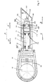
- FIG. 1 the invention is explained in more detail using an exemplary embodiment. Shown is the adjusting cylinder 71 receiving head piece 61 of a Elektrodentragarms. Assigned to the pressure cell 91 the adjusting cylinder 71 on the bottom side outside the Anstellzylinders.
- the clamping yoke 62 is displaceable in the axial direction in the direction of the double arrow A. Moves in the direction of the arrow A I , he puts the electrode 81 against the contact jaw 63 firmly.
- the pressure cell 91 Upstream of the bottom 72 of the Anstellzylinders 71 is the pressure cell 91, which is penetrated by a central passage 911, which merges into a opening in the bottom space 716 of the Anstellzylinders 71 721 in the bottom 72 of the Anstellzylinders.
- the pressure medium line 912 for the supply of the solution pressure in the bottom space 716 of the Anstellzylinders 71 is connected to the passage 911.
- 913 indicates the connection for a line leading to the far-off measured value display (control room), which transmits the pressure present in the pressure cell 91.
- the force subject to the measurement stands in the illustrated solution ( Fig. 1 ) on the pressure cell 91 via the cylinder bottom 72, with which the pressure cell 91 is non-positively summarized.
- the pressure cell 91 with the cylinder bottom 72 in the illustrated case on the outgoing from the bottom 72 nozzle 722, between which and the pressure cell on the neck defining screw 724 is clamped.
- the screw 724 then serves to adjust the desired bias. With 723 of the nozzle 722 interspersed, detachable (717), the adjusting cylinder 71 in Elektrodentragarm 11 defining abutment.
- the adjusting cylinder 71 If the clamping pressure originating from the constituent part of the adjusting cylinder 71 and falling below the electrode 81 determines a critical value which no longer guarantees clamping of the electrode, this state is indicated by the pressure measuring cell 91 assigned to the setting cylinder 71 in the oven-type control room, which receives operating personnel Thus, without further notice that it is necessary, the adjusting cylinder 71, at least the constituent of the Anstellzylinders forming spring package 714 to replace.
Landscapes
- Engineering & Computer Science (AREA)
- Physics & Mathematics (AREA)
- Plasma & Fusion (AREA)
- Analytical Chemistry (AREA)
- General Engineering & Computer Science (AREA)
- Chemical & Material Sciences (AREA)
- Mechanical Engineering (AREA)
- General Physics & Mathematics (AREA)
- Measuring Fluid Pressure (AREA)
- Furnace Details (AREA)
- Investigating Or Analyzing Materials By The Use Of Electric Means (AREA)
- Waste-Gas Treatment And Other Accessory Devices For Furnaces (AREA)
- Discharge Heating (AREA)
Abstract
Description
Vorrichtung zur Überwachung des von einem Anstellzylinder herrührenden Spanndrucks, mit dem die auswechselbare Elektrode am Elektrodentragarm festgelegt wird und mit der Vorrichtung realisierbare Verfahren zur Überwachung des SpanndrucksDevice for monitoring the clamping pressure resulting from a setting cylinder, with which the interchangeable electrode is fixed to the electrode support arm and with the device feasible method for monitoring the clamping pressure
Die Erfindung betrifft eine Vorrichtung zur Überwachung des von einem Anstellzylinder herrührenden Spanndrucks, mit dem die auswechselbare Elektrode am Elektrodentragarm festgelegt wird und mit der Vorrichtung realisierbare Verfahren zur Überwachung des Spanndrucks.The invention relates to a device for monitoring the pressure resulting from a setting cylinder, with which the interchangeable electrode is fixed to the electrode support arm and with the device feasible method for monitoring the clamping pressure.
Nach dem Stand der Technik erfolgt die Einspannung der dem Elektrodentragarm von Elektroöfen auswechselbar zuzuordnenden Elektrode in der dafür vorgesehenen, am Tragarm ausgebildeten Aufnahme mit Hilfe von einstufigen Zylindern, deren Kolbenstange unter Federdruck ein- bzw. ausfahrend, die Klemmung der Elektrode in der Aufnahme herbeiführt. Je nach Einbausituation des Anstellzylinders befinden sich die Andruckfedern im Ringraum oder aber im bodenseitigen Zylinderraum des Anstellzylinders. Das Lösen der Einspannung wird durch Einspeisung von Druckmittel in den bodenseitigen Zylinderraum oder aber in den Ringraum des Anstellzylinders bewirkt, unter dessen Einwirkung das Aus- bzw. Einfahren der Kolbenstange gegen die die Ein- bzw. Ausfahrsituation bewirkende Kraft der Anstellfedern erfolgt. Um sicherzustellen, dass eine hinreichende Spannkraft für die Elektrodeneinspannung während des laufenden Betriebes vorliegt, bedarf es bislang in regelmäßigen Abständen der Überprüfung der Spannkraft dergestalt, dass bei aus der Elektrodenaufnahme entnommener Elektrode ein auf die Elektrode und damit dann auch auf die Aufnahme ausgelegter Spanndruckmesser in die Elektrodenaufnahme überführt und den aktuellen Spanndruck messend angestellt wird (Flohe-Katalog "
Der
Ausgehend vom Stand der Technik liegt der Erfindung die Aufgabe zugrunde, in erster Linie die Möglichkeit der Überwachung des Spanndrucks der die Festlegung der Elektrode in der Elektrodenaufnahme eines Tragarms eines Elektroofens bewirkenden Druckfeder im laufenden Betrieb zu eröffnen, aber auch die Möglichkeit des Auswechselns des Spannzylinders zu erweitern, dann auch nur das Federpaket anstelle des kompletten Spannzylinders zu wechseln.Based on the prior art, the present invention seeks to open in the first place, the possibility of monitoring the clamping pressure of fixing the electrode in the electrode holder of a support arm of an electric furnace causing compression spring during operation, but also the possibility of replacing the clamping cylinder then change only the spring package instead of the complete clamping cylinder.
Die vorrangige Aufgabe wird erfindungsgemäß mit einer Vorrichtung zur Überwachung des von einem Anstellzylinder herrührenden Spanndrucks, mit dem die auswechselbare Elektrode eines Elektroofens am freien Ende des Elektrodentragarms festgelegt ist, gelöst, die folgende konstruktiven Merkmale aufweist:
- eine den Spanndruck messende Druckmessdose,
- die dem Anstellzylinder bodenseitig zugeordnet ist und vom Spanndruck beaufschlagt wird,
- eine ofenferne Druckmessanzeige, bei der die Messwerte über eine von der Druckmessdose ausgehende Leitung auflaufen,
- einen vom Zylinderboden ausgehenden, die Druckmessdose durchsetzenden Stutzen,
- und eine am Überstand des Stutzens über die Druckmessdose angesetzte, gegen die Druckmessdose zur Anlage kommende, die Druckmessdose kraftschlüssig mit dem Zylinderboden zusammenfassende Verschraubung.
- a pressure measuring cell measuring the clamping pressure,
- which is associated with the setting cylinder on the bottom side and is acted upon by the clamping pressure,
- an oven-remote pressure measuring display, in which the measured values accumulate over a line coming from the pressure cell,
- an outgoing from the cylinder bottom, the pressure cell penetrating nozzle,
- and one on the supernatant of the connecting piece via the pressure measuring box, against the pressure cell to the system coming, the pressure load cell frictionally with the cylinder bottom summarizing screw.
Die unmittelbare leitungsgebundene Vermittlung des Spanndrucks im laufenden Betrieb an eine ofenferne Messwertanzeige erübrigt das Ansetzen eines Spanndruckmessers an die Elektrodenaufnahme, bei aus der Aufnahme entnommener Elektrode zu Lasten des laufenden Schmelzbetriebes, sie signalisiert dem Ofenpersonal dann auch Druckabfall, womit sich ein Lösen der eingespannten Elektrode während des laufenden Betriebes mit entsprechenden Konsequenzen für den Betriebsablauf vermeiden läßt. Die spezielle Zuordnung der Druckmessdose zum in den Elektrodentragarm eingelagerten Anstellzylinder eröffnet dann auch die Möglichkeit, bei erforderlich werdendem Auswechseln des Spannzylinders diese zum rückwärtigen Ende des Elektrodentragarms hin auszubauen und einen den ausgebauten Spannzylinder ersetzenden Spannzylinder vom rückwärtigen Ende in den Elektrodentragarm zu überführen.The direct line-bound mediation of the clamping pressure during operation to a remotely measured value display eliminates the need to attach a clamping pressure gauge to the electrode holder, taken from the recording electrode at the expense of ongoing melting operation, it also signals the oven staff pressure drop, bringing a release of the clamped electrode during the ongoing operation with appropriate consequences for the operation can be avoided. The special assignment of the pressure cell to the Anstellzylinder stored in the Elektrodentragarm then also opens up the possibility, if necessary to be replaced by replacing the clamping cylinder to expand it to the rear end of the Elektrodentragarms out and to replace the removed clamping cylinder replacing the clamping cylinder from the rear end into the electrode support arm.
Eine vorteilhafte Ausgestaltung der Lösung ist durch ein den dem Elektrodentragarm zugeordneten Anstellzylinder im Elektrodentragarm durch ein sich einerseits am Elektrodentragarm und andererseits am Anstellzylinder abstützendes, dem vom Zylinderboden ausgehenden Stutzen durchsetzendes, durch eine Verschraubung mit dem Elektrodentragarm lösbar zusammengefasstes, der Druckmessdose vorgelagertes Widerlager. Damit ist die Möglichkeit eröffnet, den Spannzylinder in beiden Richtungen, also sowohl zur Tragarmsäule als auch zum Elektroofen hin, aus- und dann auch wieder einzubauen. Vorgesehen sein kann, dass die Druckmessdose einen sich in den Bodenraum des Anstellzylinders fortsetzenden Durchgang für die Einspeisung des Lösungsdruckmittels in den Bodenraum aufweist. Damit entfällt der unmittelbare Anschluss der Druckmessleitung an den Spannzylinder, also das dafür erforderliche zusätzliche Anbohren des Spannzylinders.An advantageous embodiment of the solution is by a the Elektrodentragarm associated Anstellzylinder in Elektrodentragarm by a on the one hand on Elektrodentragarm and on the other supporting the Anstellzylinder, the bottom of the cylinder bottom extending stub, by a screw with the Elektrodentragarm releasably summarized, the pressure cell upstream bearing abutment. This opens up the possibility of removing and then reinstalling the clamping cylinder in both directions, ie both to the support arm column and to the electric furnace. It can be provided that the pressure cell has a continuation in the bottom space of the Anstellzylinders passage for the supply of the solvent pressure medium in the bottom space. This eliminates the immediate connection of the pressure measuring line to the clamping cylinder, so the required additional drilling of the clamping cylinder.
Eine bei Unterschreiten des Mindestspanndrucks ansprechende akustische und/oder optische Signalgabe stellt sicher, daß das Ofenpersonal auf den Spanndruckabfall aufmerksam wird. Vorgesehen sein kann sowohl die diskrete als auch die kontinuierliche Übermittlung der Messwerte an die Messwertanzeige.A falling below the minimum clamping pressure responsive acoustic and / or visual signaling ensures that the oven staff is aware of the clamping pressure drop. Both the discrete and the continuous transmission of the measured values to the measured value display can be provided.
In der Zeichnung (
Dem Boden 72 des Anstellzylinders 71 vorgelagert ist die Druckmessdose 91, die von einem zentrischen Durchgang 911 durchsetzt ist, der in eine im Bodenraum 716 des Anstellzylinders 71 mündende Bohrung 721 im Boden 72 des Anstellzylinders übergeht. Auf der vom Anstellzylinder 71 abgewandten Seite der Druckmessdose ist an den Durchgang 911 die Druckmittelleitung 912 für die Einspeisung des Lösungsdrucks in den Bodenraum 716 des Anstellzylinders 71 angeschlossen. Mit 913 ist der Anschluß für eine zur ofenfernen Messwertanzeige (Messwarte) führende, den in der Druckmessdose 91 anstehenden Druck übermittelnde Leitung bezeichnet. Werden die das Widerlager festlegenden Schrauben 770 gelöst, dann auch die Lösungsdruckmittelleitung 912, ist die Möglichkeit eröffnet, den Spannzylinder 71 sowohl zur Tragarmsäule als auch zum Elektroofen hin auszubauen (Hub B) und in entsprechender Weise den neuen Spannzylinder 71 dann auch wieder in den Tragarm 61, d.h. in die darin befindliche Aufnahme 611, einzufügen (Hub C). Mit 715, 715I sind am Elektrodentragarm 61 ausgebildete Führungen bezeichnet, die den lagerechten Aus- und Einbau des Spannzylinders 71 sicherstellen.Upstream of the
Die der Messung unterliegende Kraft steht bei der dargestellten Lösung (
Die Verschraubung 724 dient dann auch der Einstellung der gewünschten Vorspannung. Mit 723 ist das vom Stutzen 722 durchsetzte, lösbare (717), den Anstellzylinder 71 im Elektrodentragarm 11 festlegende Widerlager bezeichnet.The
Unterschreitet der vom Bestandteil des Anstellzylinders 71 bildenden Federpakets 714 herrührende, die Elektrode 81 festlegende Spanndruck einen kritischen Wert, der die Einspannung der Elektrode nicht mehr gewährleistet, wird dieser Zustand von der dem Anstellzylinder 71 zugeordneten Druckmessdose 91 in der ofenfemen Messwarte angezeigt, das Bedienungspersonal erhält damit ohne weiteres den Hinweis, daß es erforderlich wird, den Anstellzylinder 71, zumindest das Bestandteil des Anstellzylinders bildende Federpaket 714, auszuwechseln.If the clamping pressure originating from the constituent part of the adjusting
- 6161
- Elektrodentragarm / KopfstückElectrode support arm / head piece
- 611611
- Aufnahmeadmission
- 612, 612I 612, 612 I
- Führungguide
- 6262
- Spannbügeltensioning bow
- 6363
- Kontaktbackecontact jaw
- 7171
- AnstellzylinderAdjusting cylinder
- 711711
- Kolbenstangepiston rod
- 712712
- Kolbenpiston
- 713713
- Ringraumannulus
- 714714
- Federpaketspring assembly
- 716716
- Bodenraumfloor space
- 717717
- Verschraubungscrew
- 7272
- Zylinderbodencylinder base
- 721721
- Bohrungdrilling
- 722722
- StutzenSupport
- 723723
- Widerlagerabutment
- 724724
- Verschraubung / MutterScrew connection / nut
- 8181
- Elektrodeelectrode
- 9191
- Druckmeßdoseload cell
- 911911
- Durchgangpassage
- 912912
- Druckmittelleitung für den LösungsdruckPressure medium line for the solution pressure
- 913913
- zur Spanndruckmeßanzeige führende Leitungto the Spanndruckmeßanzeige leading line
- AA
- Hub des SpannzylindersStroke of the clamping cylinder
- AI A I
- LösungshubLösungshub
- AII A II
- Spannhubclamping stroke
- BB
- Ausbau zur Tragarmsäule hinRemoval to the Tragarmsäule out
- CC
- Ausbau zum Elektroofen hinRemoval to the electric oven
Claims (6)
- Device for monitoring the clamping pressure that originates from an adjusting cylinder, at which clamping pressure an exchangeable electrode (81) of an electric furnace is clamped at the free end of the electrode supporting arm (61), characterized by the following features:a pressure load cell (91) that measures the clamping pressure,said pressure load cell being assigned to the bottom of the adjusting cylinder (71) and being impinged upon by the clamping pressure,a pressure load display which is remote from the furnace and on which the measured values are represented via a line (913) that extends from the pressure load cell (91),a connecting piece (722) that extends from the cylinder bottom (72) and passes through the pressure load cell (91)and a screw connection (724) that is arranged at the overhang of the connecting piece (722) over the pressure load cell (91), abuts against the pressure load cell (91) and joins the pressure load cell with the cylinder bottom (72) in a force-fitting manner.
- Device according to Claim 1, characterized by an abutment (723) that is mounted upstream of the pressure load cell (91), is joined in a detachable manner to the electrode supporting arm (61) by means of a screw connection (717), passes through the connecting piece (722) that extends from the cylinder bottom (72), supports the adjusting cylinder (71), which is assigned to the electrode supporting arm (61), in the electrode supporting arm (61) on one side on the electrode supporting arm (61) and on the other side on the adjusting cylinder (71).
- Device according to Claim 1 or Claim 2, characterized in that the pressure load cell (91) has a bore (721) which continues in the bottom space (716) of the adjusting cylinder (71) for the supplying of pressure medium into the bottom space (716) of the adjusting cylinder (71).
- Method for monitoring the clamping pressure that originates from the adjusting cylinder, at which clamping pressure the exchangeable electrode of an electric furnace is clamped at the free end of the electrode supporting arm, using a device in accordance with one of Claims 1 to 3, characterized by an acoustic and/or optical signalling that is integrated in the measured-value display and responds when the clamping pressure falls below a minimum value.
- Method according to Claim 4, characterized by the discrete transmission of the measured values to the measured value display.
- Method according to Claim 4, characterized by a continuous transmission of the measured values to the measured value display.
Applications Claiming Priority (5)
| Application Number | Priority Date | Filing Date | Title |
|---|---|---|---|
| DE10239470 | 2002-08-28 | ||
| DE2002139470 DE10239470A1 (en) | 2002-08-28 | 2002-08-28 | Monitoring clamping pressure exerted by actuating cylinder which clamps electrode in electric furnace involves continuously measuring clamping pressure using pressure cell assigned to cylinder |
| DE10311426 | 2003-03-13 | ||
| DE10311426.2A DE10311426B4 (en) | 2002-12-20 | 2003-03-13 | Clamping for a replaceable electrode of an electrofusion unit |
| PCT/EP2003/009530 WO2004025202A1 (en) | 2002-08-28 | 2003-08-28 | Methods and devices for monitoring a clamping pressure, which is exerted by an actuating cylinder and fixes an interchangeable electrode to the electrode support arm |
Publications (2)
| Publication Number | Publication Date |
|---|---|
| EP1537372A1 EP1537372A1 (en) | 2005-06-08 |
| EP1537372B1 true EP1537372B1 (en) | 2009-10-21 |
Family
ID=31995045
Family Applications (1)
| Application Number | Title | Priority Date | Filing Date |
|---|---|---|---|
| EP03794958A Expired - Lifetime EP1537372B1 (en) | 2002-08-28 | 2003-08-28 | Methods and devices for monitoring a clamping pressure, which is exerted by an actuating cylinder and fixes an interchangeable electrode to the electrode support arm |
Country Status (6)
| Country | Link |
|---|---|
| US (1) | US7194917B2 (en) |
| EP (1) | EP1537372B1 (en) |
| AT (1) | ATE446492T1 (en) |
| DE (1) | DE50312058D1 (en) |
| ES (1) | ES2332270T3 (en) |
| WO (1) | WO2004025202A1 (en) |
Cited By (2)
| Publication number | Priority date | Publication date | Assignee | Title |
|---|---|---|---|---|
| DE102010025236A1 (en) | 2010-02-18 | 2011-08-18 | SMS Siemag AG, 40237 | Electrode support arm of a smelting metallurgical furnace |
| CN102724778A (en) * | 2012-06-20 | 2012-10-10 | 柳州市金螺机械有限责任公司 | Electrode clamping device for electric arc furnace |
Families Citing this family (7)
| Publication number | Priority date | Publication date | Assignee | Title |
|---|---|---|---|---|
| CH701524A1 (en) * | 2009-07-22 | 2011-01-31 | Kistler Holding Ag | Electromechanical joining module with load cells. |
| DE102009034407A1 (en) * | 2009-07-23 | 2011-02-03 | Fuchs Technology Holding Ag | Electrode support arm with locally fixed conductor |
| US9610133B2 (en) | 2010-03-16 | 2017-04-04 | Covidien Lp | Wireless laparoscopic camera |
| RU2639900C2 (en) * | 2012-06-28 | 2017-12-25 | Жак ВАНТЕ | Clamping device for electrode |
| FI125248B (en) * | 2013-07-05 | 2015-07-31 | Outotec Finland Oy | Method and system for measuring the clamping pressure in an electrode control device |
| US9581532B2 (en) | 2014-12-03 | 2017-02-28 | International Business Machines Corporation | Substrate edge clamping force tester |
| CN118100028B (en) * | 2024-04-26 | 2024-08-06 | 中铁一局集团电务工程有限公司 | Cable installation equipment for generator set |
Citations (1)
| Publication number | Priority date | Publication date | Assignee | Title |
|---|---|---|---|---|
| US4182927A (en) * | 1978-08-04 | 1980-01-08 | Dixie Bronze Company | Electrode holders having differential clamping devices |
Family Cites Families (10)
| Publication number | Priority date | Publication date | Assignee | Title |
|---|---|---|---|---|
| US3937869A (en) * | 1974-10-08 | 1976-02-10 | Republic Steel Corporation | Force sensing control apparatus and method for electric arc furnaces |
| AU2536777A (en) * | 1976-06-11 | 1978-11-23 | Univ Newcastle | Instructional sporting implement handle |
| EP0558194A1 (en) * | 1992-02-25 | 1993-09-01 | Robert Edward Best | Measuring calliper |
| US5445613A (en) * | 1993-07-16 | 1995-08-29 | Rocky Mountain Research, Inc. | Condition detection system and clamp |
| US5417464A (en) * | 1993-12-10 | 1995-05-23 | Cascade Corporation | Slip-correcting load-clamping system |
| DE4446538A1 (en) * | 1994-12-24 | 1996-06-27 | Bosch Gmbh Robert | Hydraulic tensioning device e.g. for programmable machine tool |
| JPH10291105A (en) * | 1997-04-18 | 1998-11-04 | Toyota Motor Corp | Tool clamping force measuring device |
| US6520022B1 (en) * | 2000-11-08 | 2003-02-18 | The Reliable Automatic Sprinkler Co., Inc. | Direct connect pressure tester arrangement |
| CA2455596A1 (en) * | 2000-12-15 | 2002-06-20 | Amir Belson | Obstetrical imaging system and integrated fetal vacuum extraction system |
| US6758098B1 (en) * | 2002-02-20 | 2004-07-06 | The United States Of America As Represented By The Administrator Of The National Aeronautics And Space Administration | Force-measuring clamp |
-
2003
- 2003-08-28 EP EP03794958A patent/EP1537372B1/en not_active Expired - Lifetime
- 2003-08-28 DE DE50312058T patent/DE50312058D1/en not_active Expired - Lifetime
- 2003-08-28 AT AT03794958T patent/ATE446492T1/en active
- 2003-08-28 ES ES03794958T patent/ES2332270T3/en not_active Expired - Lifetime
- 2003-08-28 WO PCT/EP2003/009530 patent/WO2004025202A1/en not_active Ceased
-
2005
- 2005-02-23 US US11/074,240 patent/US7194917B2/en not_active Expired - Lifetime
Patent Citations (1)
| Publication number | Priority date | Publication date | Assignee | Title |
|---|---|---|---|---|
| US4182927A (en) * | 1978-08-04 | 1980-01-08 | Dixie Bronze Company | Electrode holders having differential clamping devices |
Cited By (3)
| Publication number | Priority date | Publication date | Assignee | Title |
|---|---|---|---|---|
| DE102010025236A1 (en) | 2010-02-18 | 2011-08-18 | SMS Siemag AG, 40237 | Electrode support arm of a smelting metallurgical furnace |
| WO2011101271A1 (en) | 2010-02-18 | 2011-08-25 | Sms Siemag Ag | Electrode arm of a metallurgical melting furnace |
| CN102724778A (en) * | 2012-06-20 | 2012-10-10 | 柳州市金螺机械有限责任公司 | Electrode clamping device for electric arc furnace |
Also Published As
| Publication number | Publication date |
|---|---|
| ES2332270T3 (en) | 2010-02-01 |
| ATE446492T1 (en) | 2009-11-15 |
| EP1537372A1 (en) | 2005-06-08 |
| DE50312058D1 (en) | 2009-12-03 |
| US7194917B2 (en) | 2007-03-27 |
| US20050257624A1 (en) | 2005-11-24 |
| WO2004025202A1 (en) | 2004-03-25 |
Similar Documents
| Publication | Publication Date | Title |
|---|---|---|
| EP1125696B1 (en) | Weight balancing device for a robot arm | |
| EP1537372B1 (en) | Methods and devices for monitoring a clamping pressure, which is exerted by an actuating cylinder and fixes an interchangeable electrode to the electrode support arm | |
| DE1923813C3 (en) | Method and device for readjusting the clamping force in a pressure or injection molding machine in column design with toggle press | |
| EP0999911B1 (en) | Device for separating the rod and cap of a connecting rod by breaking | |
| DE2062792C3 (en) | Support guide frame for continuous casting plants | |
| DE102016122170A1 (en) | Welding tongs in C-shape | |
| EP0298218B1 (en) | Remelting furnace with ingot gravimetric control | |
| EP3129147B1 (en) | Gyratory crusher head fixing mechanism | |
| EP0195952A2 (en) | Gripping devices for idle stage areas of a transfer press | |
| DE29710142U1 (en) | Device for the fully automatic changing of electrode caps on spot welding robots | |
| DD249323A5 (en) | LIFTING DEVICE ON A MELTING FURNACE FOR A COMBUSTION FURNACE FOR THE CONTINUOUS PRODUCTION OF SELF-COCOKING CARBON ELECTRODES | |
| DE19781923C2 (en) | Guide arrangement for a cast strand in a continuous casting machine | |
| EP0059181B1 (en) | Method and apparatus for controlling the melting rate of an electrode by electroslag remelting | |
| DE69809966T2 (en) | WEIGHT BALANCE ARRANGEMENT | |
| EP1432291B1 (en) | Clamping device for changeable electrode of an electric furnace | |
| DE3202051C2 (en) | ||
| DE2448141A1 (en) | HANDLING DEVICE FOR MEASURING CARTRIDGES FOR MEASURING PHYSICAL AND / OR CHEMICAL QUANTITIES IN MELTES, IN PARTICULAR IN POURS OR CONVERTERS | |
| DE1458240C3 (en) | A strand transport device downstream of a continuous casting mold | |
| DE3921238C2 (en) | ||
| DE3026861A1 (en) | Pneumatic or hydraulic pile driver and extractor appliance - has coaxial holes in hammer plunger and striker head | |
| DE2332299B2 (en) | LOWER SHEET HOLDER FOR MECHANICAL PRESSES | |
| EP0512657B1 (en) | Device for coupling the current feed to a metallurgical vessel | |
| DE10239470A1 (en) | Monitoring clamping pressure exerted by actuating cylinder which clamps electrode in electric furnace involves continuously measuring clamping pressure using pressure cell assigned to cylinder | |
| DE529401C (en) | Device for attaching a new pipe part to the existing casing of a borehole | |
| DE1440991B2 (en) | REPLACEMENT DEVICE FOR ELECTRODES OF ELECTRIC OVEN |
Legal Events
| Date | Code | Title | Description |
|---|---|---|---|
| PUAI | Public reference made under article 153(3) epc to a published international application that has entered the european phase |
Free format text: ORIGINAL CODE: 0009012 |
|
| 17P | Request for examination filed |
Effective date: 20050329 |
|
| AK | Designated contracting states |
Kind code of ref document: A1 Designated state(s): AT BE BG CH CY CZ DE DK EE ES FI FR GB GR HU IE IT LI LU MC NL PT RO SE SI SK TR |
|
| AX | Request for extension of the european patent |
Extension state: AL LT LV MK |
|
| DAX | Request for extension of the european patent (deleted) | ||
| 17Q | First examination report despatched |
Effective date: 20061006 |
|
| GRAP | Despatch of communication of intention to grant a patent |
Free format text: ORIGINAL CODE: EPIDOSNIGR1 |
|
| GRAS | Grant fee paid |
Free format text: ORIGINAL CODE: EPIDOSNIGR3 |
|
| GRAA | (expected) grant |
Free format text: ORIGINAL CODE: 0009210 |
|
| AK | Designated contracting states |
Kind code of ref document: B1 Designated state(s): AT BE BG CH CY CZ DE DK EE ES FI FR GB GR HU IE IT LI LU MC NL PT RO SE SI SK TR |
|
| REG | Reference to a national code |
Ref country code: GB Ref legal event code: FG4D Free format text: NOT ENGLISH |
|
| REG | Reference to a national code |
Ref country code: CH Ref legal event code: EP |
|
| REG | Reference to a national code |
Ref country code: IE Ref legal event code: FG4D |
|
| REF | Corresponds to: |
Ref document number: 50312058 Country of ref document: DE Date of ref document: 20091203 Kind code of ref document: P |
|
| REG | Reference to a national code |
Ref country code: SE Ref legal event code: TRGR |
|
| REG | Reference to a national code |
Ref country code: GR Ref legal event code: EP Ref document number: 20090403216 Country of ref document: GR |
|
| REG | Reference to a national code |
Ref country code: ES Ref legal event code: FG2A Ref document number: 2332270 Country of ref document: ES Kind code of ref document: T3 |
|
| NLV1 | Nl: lapsed or annulled due to failure to fulfill the requirements of art. 29p and 29m of the patents act | ||
| PG25 | Lapsed in a contracting state [announced via postgrant information from national office to epo] |
Ref country code: PT Free format text: LAPSE BECAUSE OF FAILURE TO SUBMIT A TRANSLATION OF THE DESCRIPTION OR TO PAY THE FEE WITHIN THE PRESCRIBED TIME-LIMIT Effective date: 20100222 |
|
| REG | Reference to a national code |
Ref country code: IE Ref legal event code: FD4D |
|
| PG25 | Lapsed in a contracting state [announced via postgrant information from national office to epo] |
Ref country code: SI Free format text: LAPSE BECAUSE OF FAILURE TO SUBMIT A TRANSLATION OF THE DESCRIPTION OR TO PAY THE FEE WITHIN THE PRESCRIBED TIME-LIMIT Effective date: 20091021 |
|
| PG25 | Lapsed in a contracting state [announced via postgrant information from national office to epo] |
Ref country code: EE Free format text: LAPSE BECAUSE OF FAILURE TO SUBMIT A TRANSLATION OF THE DESCRIPTION OR TO PAY THE FEE WITHIN THE PRESCRIBED TIME-LIMIT Effective date: 20091021 Ref country code: DK Free format text: LAPSE BECAUSE OF FAILURE TO SUBMIT A TRANSLATION OF THE DESCRIPTION OR TO PAY THE FEE WITHIN THE PRESCRIBED TIME-LIMIT Effective date: 20091021 Ref country code: BG Free format text: LAPSE BECAUSE OF FAILURE TO SUBMIT A TRANSLATION OF THE DESCRIPTION OR TO PAY THE FEE WITHIN THE PRESCRIBED TIME-LIMIT Effective date: 20100121 Ref country code: RO Free format text: LAPSE BECAUSE OF FAILURE TO SUBMIT A TRANSLATION OF THE DESCRIPTION OR TO PAY THE FEE WITHIN THE PRESCRIBED TIME-LIMIT Effective date: 20091021 Ref country code: IE Free format text: LAPSE BECAUSE OF FAILURE TO SUBMIT A TRANSLATION OF THE DESCRIPTION OR TO PAY THE FEE WITHIN THE PRESCRIBED TIME-LIMIT Effective date: 20091021 |
|
| PLBE | No opposition filed within time limit |
Free format text: ORIGINAL CODE: 0009261 |
|
| STAA | Information on the status of an ep patent application or granted ep patent |
Free format text: STATUS: NO OPPOSITION FILED WITHIN TIME LIMIT |
|
| PG25 | Lapsed in a contracting state [announced via postgrant information from national office to epo] |
Ref country code: CZ Free format text: LAPSE BECAUSE OF FAILURE TO SUBMIT A TRANSLATION OF THE DESCRIPTION OR TO PAY THE FEE WITHIN THE PRESCRIBED TIME-LIMIT Effective date: 20091021 Ref country code: SK Free format text: LAPSE BECAUSE OF FAILURE TO SUBMIT A TRANSLATION OF THE DESCRIPTION OR TO PAY THE FEE WITHIN THE PRESCRIBED TIME-LIMIT Effective date: 20091021 |
|
| 26N | No opposition filed |
Effective date: 20100722 |
|
| PG25 | Lapsed in a contracting state [announced via postgrant information from national office to epo] |
Ref country code: MC Free format text: LAPSE BECAUSE OF NON-PAYMENT OF DUE FEES Effective date: 20100831 |
|
| REG | Reference to a national code |
Ref country code: CH Ref legal event code: PL |
|
| GBPC | Gb: european patent ceased through non-payment of renewal fee |
Effective date: 20100828 |
|
| PG25 | Lapsed in a contracting state [announced via postgrant information from national office to epo] |
Ref country code: CH Free format text: LAPSE BECAUSE OF NON-PAYMENT OF DUE FEES Effective date: 20100831 Ref country code: LI Free format text: LAPSE BECAUSE OF NON-PAYMENT OF DUE FEES Effective date: 20100831 |
|
| PG25 | Lapsed in a contracting state [announced via postgrant information from national office to epo] |
Ref country code: GB Free format text: LAPSE BECAUSE OF NON-PAYMENT OF DUE FEES Effective date: 20100828 |
|
| PGFP | Annual fee paid to national office [announced via postgrant information from national office to epo] |
Ref country code: FI Payment date: 20110822 Year of fee payment: 9 |
|
| PG25 | Lapsed in a contracting state [announced via postgrant information from national office to epo] |
Ref country code: CY Free format text: LAPSE BECAUSE OF FAILURE TO SUBMIT A TRANSLATION OF THE DESCRIPTION OR TO PAY THE FEE WITHIN THE PRESCRIBED TIME-LIMIT Effective date: 20091021 |
|
| PG25 | Lapsed in a contracting state [announced via postgrant information from national office to epo] |
Ref country code: HU Free format text: LAPSE BECAUSE OF FAILURE TO SUBMIT A TRANSLATION OF THE DESCRIPTION OR TO PAY THE FEE WITHIN THE PRESCRIBED TIME-LIMIT Effective date: 20100422 Ref country code: NL Free format text: LAPSE BECAUSE OF FAILURE TO SUBMIT A TRANSLATION OF THE DESCRIPTION OR TO PAY THE FEE WITHIN THE PRESCRIBED TIME-LIMIT Effective date: 20091021 |
|
| PG25 | Lapsed in a contracting state [announced via postgrant information from national office to epo] |
Ref country code: FI Free format text: LAPSE BECAUSE OF NON-PAYMENT OF DUE FEES Effective date: 20120828 |
|
| REG | Reference to a national code |
Ref country code: FR Ref legal event code: PLFP Year of fee payment: 13 |
|
| PGFP | Annual fee paid to national office [announced via postgrant information from national office to epo] |
Ref country code: LU Payment date: 20150825 Year of fee payment: 13 |
|
| PGFP | Annual fee paid to national office [announced via postgrant information from national office to epo] |
Ref country code: SE Payment date: 20150824 Year of fee payment: 13 Ref country code: FR Payment date: 20150824 Year of fee payment: 13 Ref country code: AT Payment date: 20150820 Year of fee payment: 13 |
|
| REG | Reference to a national code |
Ref country code: SE Ref legal event code: EUG |
|
| REG | Reference to a national code |
Ref country code: AT Ref legal event code: MM01 Ref document number: 446492 Country of ref document: AT Kind code of ref document: T Effective date: 20160828 |
|
| PG25 | Lapsed in a contracting state [announced via postgrant information from national office to epo] |
Ref country code: SE Free format text: LAPSE BECAUSE OF NON-PAYMENT OF DUE FEES Effective date: 20160829 |
|
| REG | Reference to a national code |
Ref country code: FR Ref legal event code: ST Effective date: 20170428 |
|
| PG25 | Lapsed in a contracting state [announced via postgrant information from national office to epo] |
Ref country code: AT Free format text: LAPSE BECAUSE OF NON-PAYMENT OF DUE FEES Effective date: 20160828 |
|
| PG25 | Lapsed in a contracting state [announced via postgrant information from national office to epo] |
Ref country code: FR Free format text: LAPSE BECAUSE OF NON-PAYMENT OF DUE FEES Effective date: 20160831 |
|
| PG25 | Lapsed in a contracting state [announced via postgrant information from national office to epo] |
Ref country code: LU Free format text: LAPSE BECAUSE OF NON-PAYMENT OF DUE FEES Effective date: 20160828 |
|
| PGFP | Annual fee paid to national office [announced via postgrant information from national office to epo] |
Ref country code: TR Payment date: 20220818 Year of fee payment: 20 Ref country code: IT Payment date: 20220831 Year of fee payment: 20 Ref country code: ES Payment date: 20220919 Year of fee payment: 20 Ref country code: DE Payment date: 20220826 Year of fee payment: 20 |
|
| PGFP | Annual fee paid to national office [announced via postgrant information from national office to epo] |
Ref country code: GR Payment date: 20220819 Year of fee payment: 20 Ref country code: BE Payment date: 20220818 Year of fee payment: 20 |
|
| REG | Reference to a national code |
Ref country code: DE Ref legal event code: R071 Ref document number: 50312058 Country of ref document: DE |
|
| REG | Reference to a national code |
Ref country code: ES Ref legal event code: FD2A Effective date: 20230904 |
|
| REG | Reference to a national code |
Ref country code: BE Ref legal event code: MK Effective date: 20230828 |
|
| PG25 | Lapsed in a contracting state [announced via postgrant information from national office to epo] |
Ref country code: ES Free format text: LAPSE BECAUSE OF EXPIRATION OF PROTECTION Effective date: 20230829 |