EP1537337B1 - Highly dynamic valve servocontrol device - Google Patents
Highly dynamic valve servocontrol device Download PDFInfo
- Publication number
- EP1537337B1 EP1537337B1 EP03807769A EP03807769A EP1537337B1 EP 1537337 B1 EP1537337 B1 EP 1537337B1 EP 03807769 A EP03807769 A EP 03807769A EP 03807769 A EP03807769 A EP 03807769A EP 1537337 B1 EP1537337 B1 EP 1537337B1
- Authority
- EP
- European Patent Office
- Prior art keywords
- valve
- bushing
- drive device
- highly dynamic
- sleeve
- Prior art date
- Legal status (The legal status is an assumption and is not a legal conclusion. Google has not performed a legal analysis and makes no representation as to the accuracy of the status listed.)
- Expired - Lifetime
Links
- 230000004044 response Effects 0.000 claims description 7
- 230000005355 Hall effect Effects 0.000 claims description 5
- 238000006073 displacement reaction Methods 0.000 claims description 5
- 230000001939 inductive effect Effects 0.000 claims description 2
- 230000005540 biological transmission Effects 0.000 description 5
- 239000007788 liquid Substances 0.000 description 5
- 230000008901 benefit Effects 0.000 description 4
- 230000009471 action Effects 0.000 description 1
- 230000008859 change Effects 0.000 description 1
- 238000006243 chemical reaction Methods 0.000 description 1
- 230000007797 corrosion Effects 0.000 description 1
- 238000005260 corrosion Methods 0.000 description 1
- 230000008878 coupling Effects 0.000 description 1
- 238000010168 coupling process Methods 0.000 description 1
- 238000005859 coupling reaction Methods 0.000 description 1
- 230000001419 dependent effect Effects 0.000 description 1
- 239000012530 fluid Substances 0.000 description 1
- 238000005259 measurement Methods 0.000 description 1
- 230000003319 supportive effect Effects 0.000 description 1
Images
Classifications
-
- F—MECHANICAL ENGINEERING; LIGHTING; HEATING; WEAPONS; BLASTING
- F15—FLUID-PRESSURE ACTUATORS; HYDRAULICS OR PNEUMATICS IN GENERAL
- F15B—SYSTEMS ACTING BY MEANS OF FLUIDS IN GENERAL; FLUID-PRESSURE ACTUATORS, e.g. SERVOMOTORS; DETAILS OF FLUID-PRESSURE SYSTEMS, NOT OTHERWISE PROVIDED FOR
- F15B13/00—Details of servomotor systems ; Valves for servomotor systems
- F15B13/02—Fluid distribution or supply devices characterised by their adaptation to the control of servomotors
- F15B13/04—Fluid distribution or supply devices characterised by their adaptation to the control of servomotors for use with a single servomotor
- F15B13/0401—Valve members; Fluid interconnections therefor
- F15B13/0402—Valve members; Fluid interconnections therefor for linearly sliding valves, e.g. spool valves
-
- Y—GENERAL TAGGING OF NEW TECHNOLOGICAL DEVELOPMENTS; GENERAL TAGGING OF CROSS-SECTIONAL TECHNOLOGIES SPANNING OVER SEVERAL SECTIONS OF THE IPC; TECHNICAL SUBJECTS COVERED BY FORMER USPC CROSS-REFERENCE ART COLLECTIONS [XRACs] AND DIGESTS
- Y10—TECHNICAL SUBJECTS COVERED BY FORMER USPC
- Y10T—TECHNICAL SUBJECTS COVERED BY FORMER US CLASSIFICATION
- Y10T137/00—Fluid handling
- Y10T137/8158—With indicator, register, recorder, alarm or inspection means
- Y10T137/8225—Position or extent of motion indicator
- Y10T137/8242—Electrical
-
- Y—GENERAL TAGGING OF NEW TECHNOLOGICAL DEVELOPMENTS; GENERAL TAGGING OF CROSS-SECTIONAL TECHNOLOGIES SPANNING OVER SEVERAL SECTIONS OF THE IPC; TECHNICAL SUBJECTS COVERED BY FORMER USPC CROSS-REFERENCE ART COLLECTIONS [XRACs] AND DIGESTS
- Y10—TECHNICAL SUBJECTS COVERED BY FORMER USPC
- Y10T—TECHNICAL SUBJECTS COVERED BY FORMER US CLASSIFICATION
- Y10T137/00—Fluid handling
- Y10T137/8593—Systems
- Y10T137/86493—Multi-way valve unit
- Y10T137/86574—Supply and exhaust
- Y10T137/86622—Motor-operated
- Y10T137/8663—Fluid motor
-
- Y—GENERAL TAGGING OF NEW TECHNOLOGICAL DEVELOPMENTS; GENERAL TAGGING OF CROSS-SECTIONAL TECHNOLOGIES SPANNING OVER SEVERAL SECTIONS OF THE IPC; TECHNICAL SUBJECTS COVERED BY FORMER USPC CROSS-REFERENCE ART COLLECTIONS [XRACs] AND DIGESTS
- Y10—TECHNICAL SUBJECTS COVERED BY FORMER USPC
- Y10T—TECHNICAL SUBJECTS COVERED BY FORMER US CLASSIFICATION
- Y10T137/00—Fluid handling
- Y10T137/8593—Systems
- Y10T137/86493—Multi-way valve unit
- Y10T137/86574—Supply and exhaust
- Y10T137/8667—Reciprocating valve
- Y10T137/86694—Piston valve
- Y10T137/8671—With annular passage [e.g., spool]
Definitions
- the invention relates to a highly dynamic servo-valve control device with a tax-containing in a base body sleeve and a tax-containing in the body tax-carrying slide, wherein at least one of the control edges of the slider is designed to be displaceable relative to a control edge of the sleeve, wherein the slide and the sleeve to each other the servo valve control device comprises a primary drive device and a high frequency drive device, wherein the primary drive device comprises at least one pilot valve which influences the movement of the sleeve or the slide.
- Highly dynamic servo-valve control devices are known from the prior art. These servo-valve control devices are used in the prior art to control or regulate flow rates and / or pressures in hydraulic systems. In order to change volume flows, control cross sections are changed via a movement of control edges, for example on a slide and with the aid of a direct or indirect drive.
- Valve control is disclosed in British Patent GB 677,672A. From the European patent application EP 1 098 101 A2 a further valve control device is known. U.S. Patent 4,205,590 A also discloses another valve control device, as does U.S. Patent 4,333,387 A.
- Directly controlled valves include electromechanical converters, proportional solenoids, linear motors, plunger coils or piezoelectric transducers. Pilot-operated valves are indirectly operated drives, such as mechanical-hydraulic converters, spool valves, nozzle baffle plates and jet pipes. High dynamic servo valve control devices include both direct and pilot operated valves.
- control cross sections are bounded by two control edges, wherein the prior art, an active, i. in its position variable control edge, such as on the slider and a passive, i. fixed control edge, about on the sleeve includes.
- the achievable frequency of the servo-valve control device is specified in the existing cases via a drive of the slide and an associated drive or control electronics.
- the high-frequency drive device comprises a piezoelectric element or a plunger coil.
- the servo-valve control device comprises a sleeve position determining device for determining a position of the sleeves relative to a position of the slider. In such an embodiment, it is possible to determine the exact position of slide to sleeve and accordingly to operate the servo-valve control device.
- the sleeve position determining device comprises an eddy current sensor.
- a non-contact eddy current sensor is wear-free and robust. Also, it is extremely resistant to corrosion, which increases the longevity of the servo-valve control device.
- the servo-valve control device has an absolute position determining device for determining the position of the sleeve and slide in relation to the main body, the exact position of sleeve and slide can be advantageously determined in this variant in this variant. This allows avoiding drift of sleeve and slider in the body. Thus, a fault-free operation of the servo-valve control device is made possible even over long periods of use. An absolute measurement is only necessary if the slide and sleeve are pilot-operated.
- the sleeve position determining device or the absolute position determining device comprises an eddy current sensor, a Hall effect sensor, or an inductive displacement transducer (LVDT). Since, for example, the use of the property that a movement of electrons in the magnetic field is influenced, and a resulting deflection as voltage on the Hall effect sensor can be tapped off, this has the advantage that this is very large magnetic fields can be measured and the measuring range of Hall effect sensors is significantly larger than other sensors.
- the use of known measuring sensors in the sleeve position determining device or the absolute position determining device is particularly advantageous in this variant, since costs and troubles are avoided in the procurement of the corresponding sensors.
- the servo-valve control device comprises at least one pilot valve controlling the movement of the sleeve and a pilot valve controlling the movement of the slide. It is thus used for slide and sleeve drive side robust and particularly small-sized elements.
- the servo-valve control device comprises at least one high-frequency drive device.
- a high frequency drive device has the significant advantage of having very short response times.
- the high-frequency drive device controls at least one displacement of the sleeve. This minimizes the response time of the sleeve in the control.
- the high-frequency drive device has a high inherent momentum and a low lift
- the primary drive device has a low inherent dynamics and a large stroke.
- the high-frequency drive device complements the primary drive device in terms of its own dynamics and speed increase in the expression, particularly fast control times become possible.
- the combination of high dynamics / short stroke and medium (low) dynamics / long stroke results in a high speed gain.
- the high-frequency drive device has a low momentum and a large stroke, and the primary drive means a high momentum and has a small stroke, so in a further variant, an exchange of high-frequency drive device elements with primary drive device elements is possible.
- the advantage of a particularly fast control of the individual components of the servo-valve control device is nevertheless maintained.
- the servo-valve control device 1 is shown in a section.
- the servo-valve control device 1 comprises a base body 2 in which a sleeve 3 is mounted.
- the sleeve 3 has control edges 5.
- the control edges 5 are pronounced inside the sleeve 3.
- a slide 4 In the interior of the sleeve 3, a slide 4, with a pronounced on the circumference of the control edges 5 displaceable within the sleeve 3 pronounced.
- Through the sleeve 3 pass through openings.
- the passage openings 14 are connected to passage openings 14 in the base body 2.
- the sleeve 3 is designed displaceable via a high-frequency drive device 11 in this embodiment.
- the high-frequency drive device 11 pushes the sleeve 3 in one direction.
- the high-frequency drive device 11 comprises a piezoelectric element 13.
- the piezoelectric element 13 has the advantage of a very fast response and pushes the sleeve 3 in one direction.
- a return movement is effected by a spring 20.
- the spool 4 is moved by pressurized liquids either in one direction or the other.
- the liquids are conveyed by pilot valves 12 to one side or the other of the slide 4 from a prime mover 10.
- the pilot valves 12 are supplied via the primary drive device 10, which has supply channels for the liquid supply to the pilot valves 12, preferably with an incompressible liquid.
- the supply channels are connected to the pilot valves.
- supportive also offers the use of the spring 20.
- the position of the slider 4 in the sleeve 3 is determined by an incorporated in the sleeve 3 eddy current sensor 7, which is part of a sleeve position determining means 6.
- the housing 2 and an absolute position determining device 8 is incorporated.
- the Hall effect sensor 9 is thus located between the housing 2 and sleeve 3.
- the sleeve position determination device 6 and the absolute position determination device 8 comprise further sensors known from the prior art.
- the primary drive device 10 and the high-frequency drive device 11 also use standard known elements from the prior art.
- the movement of the sleeve 3 via a force flow through a transmission medium such as an incompressible fluid, e.g. Oil advantageously reachable, wherein the movement of the slider 4 is also achieved via a transmission medium, such as an incompressible liquid such as oil.
- a transmission medium such as an incompressible fluid, e.g. Oil
- the two transmission media are controlled separately from each other. However, the possibility of a predefined forced coupling between the two transmission media can also be used.
- the slide can be designed to be displaceable in both directions by the action of the transmission medium alone.
Description
Die Erfindung betrifft eine hochdynamische Servo-Ventilsteuervorrichtung mit einer in einem Grundkörper enthaltenen steuerkantenaufweisenden Hülse und einem in dem Grundkörper enthaltenen steuerkantenaufweisenden Schieber, wobei zumindest eine der Steuerkanten des Schiebers relativ zu einer Steuerkante der Hülse verschiebbar ausgestaltet ist, wobei der Schieber und auch die Hülse zueinander gegensinnig und relativ zu dem Grundkörper verschiebbar ausgestaltet sind, wobei die Servoventilsteuervorrichtung eine Primärantriebseinrichtung und eine Hochfrequenzantriebseinrichtung umfasst, wobei die Primärantriebseinrichtung zumindest ein die Bewegung der Hülse oder des Schiebers beeinflussendes Pilotventil umfasst.The invention relates to a highly dynamic servo-valve control device with a tax-containing in a base body sleeve and a tax-containing in the body tax-carrying slide, wherein at least one of the control edges of the slider is designed to be displaceable relative to a control edge of the sleeve, wherein the slide and the sleeve to each other the servo valve control device comprises a primary drive device and a high frequency drive device, wherein the primary drive device comprises at least one pilot valve which influences the movement of the sleeve or the slide.
Aus dem Stand der Technik sind hochdynamische Servo-Ventilsteuervorrichtungen bekannt. Diese Servo-Ventilsteuervorrichtungen werden im Stand der Technik eingesetzt, um Volumenströme und/oder Drücke in hydraulischen Systemen zu steuern oder zu regeln. Um Volumenströme zu verändern, werden, über eine Bewegung von Steuerkanten, etwa auf einem Schieber und unter zu Hilfenahme eines direkten oder indirekten Antriebes, Steuerquerschnitte verändert.Highly dynamic servo-valve control devices are known from the prior art. These servo-valve control devices are used in the prior art to control or regulate flow rates and / or pressures in hydraulic systems. In order to change volume flows, control cross sections are changed via a movement of control edges, for example on a slide and with the aid of a direct or indirect drive.
Eine Ventilsteuerung ist in der britischen Patentschrift GB 677,672 A offenbart. Aus der europäischen Patentanmeldung EP 1 098 101 A2 ist eine weitere Ventilsteuervorrichtung bekannt. Die amerikanische US-Patentschrift 4,205,590 A offenbart auch eine weitere Ventilsteuervorrichtung, ebenso wie die US-Patentschrift 4,333,387 A.Valve control is disclosed in British Patent GB 677,672A. From the European patent application EP 1 098 101 A2 a further valve control device is known. U.S. Patent 4,205,590 A also discloses another valve control device, as does U.S. Patent 4,333,387 A.
Direkt gesteuerte Ventile umfassen elektromechanische Umformer, Proportionalmagneten, Linearmotoren, Tauchspulen oder piezoelektrische Wandler. Vorgesteuerte Ventile sind indirekt betriebene Antriebe, wie u.a. mechanisch-hydraulischer Umformer, Steuerschieber, Düse-Prallplatte und Strahlrohr. Hochdynamische Servo-Ventilsteuervorrichtungen umfassen sowohl direkte als auch vorgesteuerte Ventile.Directly controlled valves include electromechanical converters, proportional solenoids, linear motors, plunger coils or piezoelectric transducers. Pilot-operated valves are indirectly operated drives, such as mechanical-hydraulic converters, spool valves, nozzle baffle plates and jet pipes. High dynamic servo valve control devices include both direct and pilot operated valves.
Bisher wird lediglich eine Position des Schiebers oder der Hülse variiert und damit auch direkt Steuerquerschnitte der Servo-Ventilsteuervorrichtung. Diese Steuerquerschnitte werden dabei durch zwei Steuerkanten eingegrenzt, wobei der Stand der Technik eine aktive, d.h. in ihrer Lage veränderliche Steuerkante, etwa auf dem Schieber und eine passive, d.h. feststehende Steuerkante, etwa auf der Hülse beinhaltet. Die erreichbare Frequenz der Servo-Ventilsteuervorrichtung wird in den bestehenden Fällen über einen Antrieb des Schiebers und eine zugehörige Ansteuer- oder Regelelektronik vorgegeben.So far, only one position of the slider or the sleeve is varied and thus directly control cross sections of the servo-valve control device. These control cross sections are bounded by two control edges, wherein the prior art, an active, i. in its position variable control edge, such as on the slider and a passive, i. fixed control edge, about on the sleeve includes. The achievable frequency of the servo-valve control device is specified in the existing cases via a drive of the slide and an associated drive or control electronics.
Direkt gesteuerte Servo-Ventilsteuervorrichtungen haben jedoch den Nachteil, dass schnelle Reaktionen nur mit kurzhubigen Ventilen realisiert werden können.However, directly controlled servo-valve control devices have the disadvantage that fast reactions can be realized only with short-stroke valves.
Es ist somit Aufgabe der vorliegenden Erfindung hochdynamisches Steuern der Servo-Ventilsteuervorrichtung zu ermöglichen.It is therefore an object of the present invention to enable highly dynamic control of the servo-valve control device.
Dies wird dadurch erreicht, dass die Hochfrequenzantriebseinrichtung ein Piezoelement oder eine Tauchspule umfasst.This is achieved in that the high-frequency drive device comprises a piezoelectric element or a plunger coil.
Die von Schieber oder Hülse bei einer Steuerbewegung zurückzulegenden Wege werden somit deutlich kleiner. Die Zeiten von einem Steuerzustand zu einem nächsten werden kürzer. Hochdynamisches Steuern der Servo-Ventilsteuervorrichtung ist somit möglich. Auch können bestehende frei erhältliche Standardbauteile in einer erfindungsgemäßen Servoventilsteuervorrichtung verwendet werden. Dies erleichtert die Beschaffung der einzelnen Elemente für die Montage.The paths to be traveled by slide or sleeve during a control movement thus become significantly smaller. The times from one control state to another become shorter. High dynamic control of the servo-valve control device is thus possible. Also, existing freely available standard components can be used in a servo valve control device according to the invention. This facilitates the procurement of the individual elements for assembly.
Es ist sowohl die Hülse als auch der Schieber bewegbar. Auch ist es möglich die zwei unterschiedlichen Antriebseinrichtungsprinzipien, Primärantriebseinrichtung und Hochfrequenzantriebseinrichtung, zu kombinieren.It is both the sleeve and the slider movable. It is also possible to combine the two different drive device principles, primary drive and high frequency drive.
Es wird vorteilhafterweise auf ein verschleißfreies und robustes Standardbauteil zurückgegriffen.It is advantageously resorted to a wear-free and robust standard component.
Es werden kleine Abmessungen der Hochfrequenzantriebseinrichtungen ermöglicht. Kleine Bauräume sind dafür wünschenswert.Small dimensions of the high-frequency drive devices are made possible. Small spaces are desirable.
Besondere Ausführungsvarianten werden in den Unteransprüchen näher beschrieben.Particular embodiments are described in more detail in the dependent claims.
Besonders Vorteilhaft ist es, wenn die Servo-Ventilsteuervorrichtung eine Hülsenpositionsbestimmungseinrichtung zum Bestimmen einer Position der Hülsen relativ zu einer Position des Schiebers umfasst. In einen derartigen Ausgestaltungsform ist es möglich die exakte Position von Schieber zu Hülse zu bestimmen und dementsprechend die Servo-Ventilsteuervorrichtung zu betätigen.It is particularly advantageous if the servo-valve control device comprises a sleeve position determining device for determining a position of the sleeves relative to a position of the slider. In such an embodiment, it is possible to determine the exact position of slide to sleeve and accordingly to operate the servo-valve control device.
Auch ist es in einer weiteren Variante besonders vorteilhaft, wenn die Hülsenpositionsbestimmungseinrichtung einen Wirbelstromsensor umfasst. Ein berührungslos arbeitender Wirbelstromsensor ist verschleißfrei und robust. Auch ist er äußerst korrosionsbeständig, wodurch die Langlebigkeit der Servo-Ventilsteuervorrichtung erhöht wird.In a further variant, it is also particularly advantageous if the sleeve position determining device comprises an eddy current sensor. A non-contact eddy current sensor is wear-free and robust. Also, it is extremely resistant to corrosion, which increases the longevity of the servo-valve control device.
Wenn in einer Variante die Servo-Ventilsteuervorrichtung eine Absolutpositionsbestimmungseinrichtung zum Ermitteln der Position von Hülse und Schieber in Relation zum Grundkörper aufweist, so kann vorteilhafterweise in dieser Variante die genaue Position von Hülse und Schieber zum Grundkörper ermittelt werden. Dies ermöglicht das Vermeiden einer Drift von Hülse und Schieber im Grundkörper. Somit wird auch über lange Nutzungsdauern ein fehlerfreies Funktionieren der Servo-Ventilsteuervorrichtung ermöglicht. Eine Absolutmessung ist nur notwendig, wenn Schieber und Hülse vorgesteuert sind.If, in one variant, the servo-valve control device has an absolute position determining device for determining the position of the sleeve and slide in relation to the main body, the exact position of sleeve and slide can be advantageously determined in this variant in this variant. This allows avoiding drift of sleeve and slider in the body. Thus, a fault-free operation of the servo-valve control device is made possible even over long periods of use. An absolute measurement is only necessary if the slide and sleeve are pilot-operated.
Besonders vorteilhaft ist es in einer Ausgestaltungsvariante auch, wenn die Hülsenpositionsbestimmungseinrichtung oder die Absolutpositionsbestimmungseinrichtung einen Wirbelstromsensor, einen Hall-Effektsensor, oder einen induktiven Wegaufnehmer (LVDT) umfasst. Da etwa das Nutzen der Eigenschaft, dass eine Bewegung von Elektronen im Magnetfeld beeinflusst wird, und eine dabei entstehende Ablenkung als Spannung am Hall-Effektsensor abgreifbar ist, hat dies den Vorteil, dass damit sehr große Magnetfelder gemessen werden können und der Messbereich von Hall-Effektsensoren deutlich größer ist als von anderen Sensoren. Das Verwenden von bekannten Messsensoren in der Hülsenpositionsbestimmungseinrichtung oder der Absolutpositionsbestimmungseinrichtung ist in dieser Variante besonders vorteilhaft, da Kosten und Mühen bei der Beschaffung der entsprechenden Sensoren vermieden werden.In one embodiment variant, it is also particularly advantageous if the sleeve position determining device or the absolute position determining device comprises an eddy current sensor, a Hall effect sensor, or an inductive displacement transducer (LVDT). Since, for example, the use of the property that a movement of electrons in the magnetic field is influenced, and a resulting deflection as voltage on the Hall effect sensor can be tapped off, this has the advantage that this is very large magnetic fields can be measured and the measuring range of Hall effect sensors is significantly larger than other sensors. The use of known measuring sensors in the sleeve position determining device or the absolute position determining device is particularly advantageous in this variant, since costs and troubles are avoided in the procurement of the corresponding sensors.
Besonders vorteilhaft ist es in einer weiteren Ausgestaltungsform auch, wenn die Servo-Ventilsteuervorrichtung zumindest ein, die Bewegung der Hülse steuerndes Pilotventil umfasst und ein, die Bewegung der Schiebers steuerndes Pilotventil umfasst. Es werden somit für Schieber und Hülse antriebsseitig robuste und besonders kleinbauende Elemente verwendet.In a further embodiment, it is also particularly advantageous if the servo-valve control device comprises at least one pilot valve controlling the movement of the sleeve and a pilot valve controlling the movement of the slide. It is thus used for slide and sleeve drive side robust and particularly small-sized elements.
Vorteilhaft ist auch in einer Variante, wenn die Servo-Ventilsteuereinrichtung zumindest eine Hochfrequenzantriebseinrichtung umfasst. Eine Hochfrequenzantriebseinrichtung hat den bedeutenden Vorteil, dass sie sehr kurze Ansprechzeiten hat.It is also advantageous in a variant when the servo-valve control device comprises at least one high-frequency drive device. A high frequency drive device has the significant advantage of having very short response times.
Vorteilhaft ist in einer Variante auch, wenn die Hochfrequenzantriebsvorrichtung zumindest eine Verschiebung der Hülse steuert. Dadurch wird die Ansprechzeit der Hülse bei der Steuerung minimiert.It is also advantageous in a variant if the high-frequency drive device controls at least one displacement of the sleeve. This minimizes the response time of the sleeve in the control.
Vorteilhaft ist es in einem weiteren Ausgestaltungsbeispiel auch, wenn die Hochfrequenzantriebseinrichtung eine hohe Eigendynamik und einen geringen Hub aufweist, und die Primärantriebseinrichtung eine geringe Eigendynamik und einen großen Hub aufweist. Dadurch das sich die Hochfrequenzantriebseinrichtung die Primärantriebseinrichtung in punkto Eigendynamik und Geschwindigkeitsverstärkung in der Ausprägung ergänzen, werden besonders schnelle Steuerzeiten möglich. Die Kombination aus hoher Dynamik / kurzem Hub und mittlere (geringe) Dynamik / langer Hub, führt zu einer hohen Geschwindigkeitsverstärkung.It is also advantageous in a further embodiment example if the high-frequency drive device has a high inherent momentum and a low lift, and the primary drive device has a low inherent dynamics and a large stroke. As a result of which the high-frequency drive device complements the primary drive device in terms of its own dynamics and speed increase in the expression, particularly fast control times become possible. The combination of high dynamics / short stroke and medium (low) dynamics / long stroke results in a high speed gain.
Wenn die Hochfrequenzantriebseinrichtung eine geringe Eigendynamik und einen großen Hub aufweist, und die Primäre Antriebseinrichtung eine hohe Eigendynamik und einen geringen Hub aufweist, so ist in einer weiteren Variante ein Austausch von Hochfrequenzantriebseinrichtungselementen mit Primärantriebseinrichtungselementen möglich. Der Vorteil einer besonders schnellen Steuerung der einzelnen Bauteile der Servo-Ventilsteuerungvorrichtung bleibt trotzdem gewahrt.If the high-frequency drive device has a low momentum and a large stroke, and the primary drive means a high momentum and has a small stroke, so in a further variant, an exchange of high-frequency drive device elements with primary drive device elements is possible. The advantage of a particularly fast control of the individual components of the servo-valve control device is nevertheless maintained.
Im folgenden werden Ausführungsbeispiele der vorliegenden Erfindung anhand einer Zeichnung näher erläutert. Es zeigt:
- Figur 1
- den Schnitt durch eine hochdynamische Servo-Ventilsteuervorrichtung.
- FIG. 1
- the section through a highly dynamic servo-valve control device.
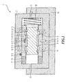
In Figur 1 ist die Servo-Ventilsteuervorrichtung 1 in einem Schnitt dargestellt. Die Servo-Ventilsteuervorrichtung 1 umfasst einen Grundkörper 2 in dem eine Hülse 3 gelagert ist. Die Hülse 3 weist Steuerkanten 5 auf. Die Steuerkanten 5 sind im Inneren der Hülse 3 ausgeprägt. Im Inneren der Hülse 3 ist ein Schieber 4, mit am Umfang ausgeprägten Steuerkanten 5 schieblich innerhalb der Hülse 3 ausgeprägt. Durch die Hülse 3 gehen Durchlassöffnungen hindurch. Die Durchlassöffnungen 14 sind mit Durchlassöffnungen 14 im Grundkörper 2 verbunden.In Figure 1, the servo-valve control device 1 is shown in a section. The servo-valve control device 1 comprises a base body 2 in which a
Die Hülse 3 ist über eine Hochfrequenzantriebseinrichtung 11 in diesem Ausführungsbeispiel verschieblich ausgestaltet. Die Hochfrequenzantriebseinrichtung 11 schiebt die Hülse 3 in die eine Richtung. Die Hochfrequenzantriebseinrichtung 11 umfasst ein Piezoelement 13. Das Piezoelement 13 hat den Vorteil eines sehr schnellen Ansprechens und schiebt die Hülse 3 in die eine Richtung. Eine Rückbewegung erfolgt durch eine Feder 20.The
In diesem Ausführungsbeispiel wird der Schieber 4 durch unter Druck stehende Flüssigkeiten entweder in die eine oder andere Richtung bewegt. Die Flüssigkeiten, werden durch Pilotventile 12 auf die eine oder andere Seite des Schiebers 4 von einer Primärantriebseinrichtung 10 befördert. Die Pilotventile 12 werden über die Primärantriebseinrichtung 10, welche Zufuhrkanäle für die Flüssigkeitsbereitstellung zu den Pilotventilen 12 aufweist, mit vorzugsweise einer inkompressiblen Flüssigkeit versorgt. Die Zufuhrkanäle sind mit dem Pilotventilen verbunden. Alternativ oder unterstützend bietet sich auch die Verwendung der Feder 20 an.In this embodiment, the
Die Position des Schiebers 4 in der Hülse 3 wird über einen in der Hülse 3 eingearbeiteten Wirbelstromsensor 7, der ein Teil einer Hülsenpositions-bestimmungseinrichtung 6 ist, bestimmt.The position of the
Im Gehäuse 2 ist auch eine Absolutpositionsbestimmungseinrichtung 8 eingearbeitet. Die Absolutpositionsbestimmungseinrichtung 8 ist in diesem Ausführungsbeispiel ein Hall-Effektsensor 9. Der Hall-Effektsensor 9 befindet sich somit zwischen Gehäuse 2 und Hülse 3. Durch die Positionsbestimmung über die Hülsenpositionsbestimmungseinrichtung 6 und die Absolutpositionsbestimmungseinrichtung 8 wird die genaue Position von Hülse 3 und Schieber 4 zum Gehäuse 2 und untereinander bestimmt. In weiteren Ausführungsbeispielen umfasst die Hülsenpositionsbestimmungseinrichtung 6 und die Absolutpositionsbestimmungseinrichtung 8 weitere aus dem Stand der Technik bekannte Sensoren.In the housing 2 and an absolute
Die Primärantriebseinrichtung 10 und die Hochfrequenzantriebseinrichtung 11 verwenden in einer weiteren Variante auch standardmäßig bekannte Elemente aus dem Stand der Technik.In a further variant, the
In einer Alternative, die nicht Teil der hier beanspruchten Erfindung ist, aber wichtig für deren Verständnis ist, wird die Bewegung der Hülse 3 über einen Kraftfluss durch ein Übertragungsmedium, wie etwa einer inkompressiblen Flüssigkeit z.B. Öl vorteilig erreichbar, wobei die Bewegung des Schiebers 4 ebenfalls über ein Übertragungsmedium, wie etwa eine inkomressible Flüssigkeit wie Öl, erreicht wird. Die beiden Übertragungsmedien sind dabei voneinander getrennt ansteuerbar. Die Möglichkeit einer vordefinierten Zwangskopplung zwischen den beiden Übertragungsmedien ist dabei aber ebenso einsetzbar.In an alternative, which is not part of the invention claimed herein but is important to its understanding, the movement of the
Der Schieber kann durch die Einwirkung des Übertragungsmediums alleine in beide Richtungen verschieblich ausgestaltet sein. Allerdings ist es auch möglich, einseitig andere Verschiebungsvorrichtungen, welche ihre Energie etwa aus einer Federkraft schöpfen, zum Verschieben von Schieber und/oder Hülse vorzusehen.The slide can be designed to be displaceable in both directions by the action of the transmission medium alone. However, it is also possible to be one-sided other displacement devices, which draw their energy as from a spring force to provide for moving slide and / or sleeve.
Claims (9)
- A highly dynamic valve servocontrol device (1) with a bushing (3) comprising control edges and contained in a main body (2), and a slide valve (4) comprising control edges and contained in the main body (2), at least one of the control edges (5) of the slide valve (4) being configured to be displaceable relative to a control edge (5) of the bushing (3), the slide valve (4) and also the bushing (3) being configured such that they are oppositely displaceable to one another and relative to the main body (2), the valve servocontrol device (1) comprising a primary drive device (10) and a high frequency drive device (11), the primary drive device (10) comprising at least one pilot valve (12) which can influence the movement of the bushing (3) or slide valve (4), characterised in that the high frequency drive device (11) comprises a piezoelement (13) or a plunger coil.
- The highly dynamic valve servocontrol device (1) according to Claim 1, characterised in that the valve servocontrol device (1) comprises a bushing position determining device (6) for determining a position of the bushing (3) in relation to a position of the slide valve (4).
- The highly dynamic valve servocontrol device (1) according to Claim 1 or 2, characterised in that the bushing position determining device (6) comprises an eddy current sensor (7).
- The highly dynamic valve servocontrol device (1) according to one of the Claims 1 to 3, characterised in that the valve servocontrol device (1) comprises an absolute position determining device (8) for the determination of the position of the bushing (3) and slide valve (4) in relation to the main body (2).
- The highly dynamic valve servocontrol device (1) according to one of the Claims 1 to 4, characterised in that the bushing position determining device (6) or the absolute position determining device (8) includes an eddy current sensor, a Hall effect sensor (9) or an inductive displacement transducer (LVDT).
- The highly dynamic valve servocontrol device (1) according to one of the Claims 1 to 5, characterised in that the valve servocontrol device (1) includes at least one pilot valve (12) controlling the movement of the bushing (3) or comprises a pilot valve (12) controlling the movement of the slide valve (4).
- The highly dynamic valve servocontrol device (1) according to one of the Claims 1 to 6, characterised in that the high frequency drive device (11) controls at least a displacement of the bushing (3).
- The highly dynamic valve servocontrol device (1) according to one of the Claims 1 to 7, characterised in that the high frequency drive device (11) exhibits a high inherent dynamic response and a low stroke, and that the primary drive device (10) exhibits a low inherent dynamic response and a large stroke.
- The highly dynamic valve servocontrol device (1) according to one of the Claims 1 to 8, characterised in that the high frequency drive device (11) exhibits a low inherent dynamic response and a large stroke, and that the primary drive device (10) exhibits a high inherent dynamic response and a low stroke.
Applications Claiming Priority (3)
| Application Number | Priority Date | Filing Date | Title |
|---|---|---|---|
| DE10241977 | 2002-09-11 | ||
| DE2002141977 DE10241977B4 (en) | 2002-09-11 | 2002-09-11 | Highly dynamic servo valve control device |
| PCT/EP2003/008550 WO2004033921A1 (en) | 2002-09-11 | 2003-08-01 | Highly dynamic valve servocontrol device |
Publications (2)
| Publication Number | Publication Date |
|---|---|
| EP1537337A1 EP1537337A1 (en) | 2005-06-08 |
| EP1537337B1 true EP1537337B1 (en) | 2006-06-14 |
Family
ID=31969060
Family Applications (1)
| Application Number | Title | Priority Date | Filing Date |
|---|---|---|---|
| EP03807769A Expired - Lifetime EP1537337B1 (en) | 2002-09-11 | 2003-08-01 | Highly dynamic valve servocontrol device |
Country Status (6)
| Country | Link |
|---|---|
| US (1) | US7721758B2 (en) |
| EP (1) | EP1537337B1 (en) |
| JP (1) | JP4198115B2 (en) |
| AU (1) | AU2003250203A1 (en) |
| DE (2) | DE10241977B4 (en) |
| WO (1) | WO2004033921A1 (en) |
Families Citing this family (7)
| Publication number | Priority date | Publication date | Assignee | Title |
|---|---|---|---|---|
| CN100535486C (en) * | 2008-03-11 | 2009-09-02 | 浙江大学 | Piezo crystal drive high speed switch valve |
| US20100148098A1 (en) * | 2008-10-03 | 2010-06-17 | Toliusis Vytautas J | Directly piloted valve assembly |
| JP5212035B2 (en) * | 2008-11-14 | 2013-06-19 | 株式会社Ihi | Valve device and servo valve |
| US8678033B2 (en) * | 2010-03-24 | 2014-03-25 | Eaton Corporation | Proportional valve employing simultaneous and hybrid actuation |
| KR101161802B1 (en) * | 2010-10-15 | 2012-07-04 | 한국도키멕유공압 주식회사 | Tunning system for hydraulic servovalve |
| US9592905B2 (en) * | 2014-11-03 | 2017-03-14 | Hamilton Sunstrand Corporation | Fuel intelligent crossfeed valve for detecting leakage in aircraft fuel tanks |
| DE102016214252A1 (en) | 2016-08-02 | 2018-02-08 | Festo Ag & Co. Kg | Valve actuation system |
Family Cites Families (10)
| Publication number | Priority date | Publication date | Assignee | Title |
|---|---|---|---|---|
| DE802298C (en) * | 1948-10-09 | 1951-02-08 | Elektro Mechanik G M B H | Hydraulic slide control with pilot control |
| GB677672A (en) * | 1949-06-08 | 1952-08-20 | Gen Motors Corp | Improved reciprocable fluid-control valve |
| US4205590A (en) * | 1978-02-06 | 1980-06-03 | Moog Inc. | Positive feedback mechanism for servocontroller of fluid operated actuator |
| US4333387A (en) * | 1978-03-21 | 1982-06-08 | Bertea Corporation | Anti-jam hydraulic servo valve |
| US4907615A (en) * | 1987-11-05 | 1990-03-13 | Schenck Pegasus Corporation | High frequency response servovalve with electrical position feedback element structure and method |
| DE19711781C2 (en) * | 1997-03-12 | 2000-05-31 | Pepperl & Fuchs | Device for detecting the position of a movably arranged magnet for generating a magnetic field through a wall made of ferromagnetic material, in particular an actuator with a movable actuator |
| DE19841660C2 (en) * | 1998-09-11 | 2003-07-10 | Audi Ag | Arrangement for the contactless measurement of valve movements in internal combustion engines |
| US6179107B1 (en) * | 1999-11-08 | 2001-01-30 | General Motors Corporation | Trim valve for a fluid operated friction torque transmitting device |
| US6789570B2 (en) * | 2001-04-23 | 2004-09-14 | Hydraforce, Inc. | Hydraulic valve with a position sensor |
| US7422033B2 (en) * | 2004-12-16 | 2008-09-09 | Husco International, Inc. | Position feedback pilot valve actuator for a spool control valve |
-
2002
- 2002-09-11 DE DE2002141977 patent/DE10241977B4/en not_active Expired - Fee Related
-
2003
- 2003-08-01 DE DE50303863T patent/DE50303863D1/en not_active Expired - Lifetime
- 2003-08-01 WO PCT/EP2003/008550 patent/WO2004033921A1/en active Application Filing
- 2003-08-01 JP JP2004542282A patent/JP4198115B2/en not_active Expired - Fee Related
- 2003-08-01 US US10/527,204 patent/US7721758B2/en not_active Expired - Fee Related
- 2003-08-01 AU AU2003250203A patent/AU2003250203A1/en not_active Abandoned
- 2003-08-01 EP EP03807769A patent/EP1537337B1/en not_active Expired - Lifetime
Also Published As
| Publication number | Publication date |
|---|---|
| DE10241977A1 (en) | 2004-04-01 |
| DE10241977B4 (en) | 2006-01-26 |
| JP2005538331A (en) | 2005-12-15 |
| US7721758B2 (en) | 2010-05-25 |
| JP4198115B2 (en) | 2008-12-17 |
| US20070079879A1 (en) | 2007-04-12 |
| EP1537337A1 (en) | 2005-06-08 |
| WO2004033921A1 (en) | 2004-04-22 |
| DE50303863D1 (en) | 2006-07-27 |
| AU2003250203A1 (en) | 2004-05-04 |
Similar Documents
| Publication | Publication Date | Title |
|---|---|---|
| DE2658928C2 (en) | ||
| EP2209998B1 (en) | Pilot-operated directional control valve, particularly for controlling an actuating cylinder of a turbo engine | |
| CH644936A5 (en) | PROPORTIONAL VALVE FOR HYDRAULIC SYSTEMS. | |
| EP2425159A1 (en) | Proportional throttle valve | |
| DE3506053A1 (en) | Switching magnet for direct current for driving a valve element | |
| EP1537337B1 (en) | Highly dynamic valve servocontrol device | |
| EP3446014B1 (en) | Actuating device for a control piston of a hydraulic valve | |
| EP3181967B1 (en) | Valve | |
| DE4446860A1 (en) | Control valve used in power generation plants | |
| EP2702460B1 (en) | Pneumatic valve and use thereof for a connected consumer | |
| WO2011000515A1 (en) | Valve arrangement | |
| EP0504465A1 (en) | Fluid transducer with piezo-electric actuator | |
| DE3513282C1 (en) | Servomotor | |
| DE102012103636A1 (en) | Bidirectional flow control valve for fluidic lifting cylinder installed in agricultural vehicle, has common valve element provided between check valves, which is displaced to equilibrium position depending upon flux direction of fluid | |
| EP0528103B2 (en) | Electrohydraulic actuator | |
| WO2011003210A1 (en) | Arrangement for providing a variable throttle cross-section for a fluid flow | |
| EP0355723B1 (en) | Device for permanently affecting a fluid-stream, especially one in a valve | |
| EP0388635B1 (en) | Electrohydraulic actuator | |
| DE3708570C2 (en) | Electro-hydraulic device for actuating a piston-like part which can be displaced in a housing bore | |
| DE2416235A1 (en) | Hydraulic pressure regulating valve - with control spool positioned by error signal from P-I-D shaping circuit with position feedback | |
| DE102018208893A1 (en) | Direct controlled hydraulic directional valve | |
| DE3925686C2 (en) | Device for continuously influencing a fluid flow in a valve | |
| DE3810139C2 (en) | ||
| EP0049714B1 (en) | Electro-magnetically controlled servomotor with follow-up action | |
| DE2515134A1 (en) | HYDRAULIC PROPORTIONAL VALVE WITH ELECTROMAGNETIC CONTROL |
Legal Events
| Date | Code | Title | Description |
|---|---|---|---|
| PUAI | Public reference made under article 153(3) epc to a published international application that has entered the european phase |
Free format text: ORIGINAL CODE: 0009012 |
|
| 17P | Request for examination filed |
Effective date: 20050217 |
|
| AK | Designated contracting states |
Kind code of ref document: A1 Designated state(s): AT BE BG CH CY CZ DE DK EE ES FI FR GB GR HU IE IT LI LU MC NL PT RO SE SI SK TR |
|
| AX | Request for extension of the european patent |
Extension state: AL LT LV MK |
|
| GRAP | Despatch of communication of intention to grant a patent |
Free format text: ORIGINAL CODE: EPIDOSNIGR1 |
|
| DAX | Request for extension of the european patent (deleted) | ||
| RBV | Designated contracting states (corrected) |
Designated state(s): CH DE IT LI |
|
| GRAS | Grant fee paid |
Free format text: ORIGINAL CODE: EPIDOSNIGR3 |
|
| GRAA | (expected) grant |
Free format text: ORIGINAL CODE: 0009210 |
|
| AK | Designated contracting states |
Kind code of ref document: B1 Designated state(s): CH DE IT LI |
|
| REG | Reference to a national code |
Ref country code: CH Ref legal event code: EP |
|
| REG | Reference to a national code |
Ref country code: CH Ref legal event code: NV Representative=s name: BOVARD AG PATENTANWAELTE |
|
| REF | Corresponds to: |
Ref document number: 50303863 Country of ref document: DE Date of ref document: 20060727 Kind code of ref document: P |
|
| PLBE | No opposition filed within time limit |
Free format text: ORIGINAL CODE: 0009261 |
|
| STAA | Information on the status of an ep patent application or granted ep patent |
Free format text: STATUS: NO OPPOSITION FILED WITHIN TIME LIMIT |
|
| 26N | No opposition filed |
Effective date: 20070315 |
|
| REG | Reference to a national code |
Ref country code: CH Ref legal event code: PFA Owner name: MOOG GMBH Free format text: MOOG GMBH#HANNS-KLEMM-STRASSE 28#71034 BOEBLINGEN (DE) -TRANSFER TO- MOOG GMBH#HANNS-KLEMM-STRASSE 28#71034 BOEBLINGEN (DE) |
|
| REG | Reference to a national code |
Ref country code: DE Ref legal event code: R082 Ref document number: 50303863 Country of ref document: DE Representative=s name: DR. JOSTARNDT & KOLLEGEN, DE Ref country code: DE Ref legal event code: R082 Ref document number: 50303863 Country of ref document: DE Representative=s name: FLEUCHAUS & GALLO PARTNERSCHAFT MBB, DE |
|
| REG | Reference to a national code |
Ref country code: DE Ref legal event code: R082 Ref document number: 50303863 Country of ref document: DE Representative=s name: FLEUCHAUS & GALLO PARTNERSCHAFT MBB, DE |
|
| PGFP | Annual fee paid to national office [announced via postgrant information from national office to epo] |
Ref country code: IT Payment date: 20160823 Year of fee payment: 14 Ref country code: CH Payment date: 20160819 Year of fee payment: 14 |
|
| REG | Reference to a national code |
Ref country code: CH Ref legal event code: PL |
|
| PG25 | Lapsed in a contracting state [announced via postgrant information from national office to epo] |
Ref country code: CH Free format text: LAPSE BECAUSE OF NON-PAYMENT OF DUE FEES Effective date: 20170831 Ref country code: LI Free format text: LAPSE BECAUSE OF NON-PAYMENT OF DUE FEES Effective date: 20170831 |
|
| PG25 | Lapsed in a contracting state [announced via postgrant information from national office to epo] |
Ref country code: IT Free format text: LAPSE BECAUSE OF NON-PAYMENT OF DUE FEES Effective date: 20170801 |
|
| REG | Reference to a national code |
Ref country code: DE Ref legal event code: R082 Ref document number: 50303863 Country of ref document: DE Representative=s name: WITHERS & ROGERS LLP, DE |
|
| PGFP | Annual fee paid to national office [announced via postgrant information from national office to epo] |
Ref country code: DE Payment date: 20190822 Year of fee payment: 17 |
|
| REG | Reference to a national code |
Ref country code: DE Ref legal event code: R119 Ref document number: 50303863 Country of ref document: DE |
|
| PG25 | Lapsed in a contracting state [announced via postgrant information from national office to epo] |
Ref country code: DE Free format text: LAPSE BECAUSE OF NON-PAYMENT OF DUE FEES Effective date: 20210302 |