EP1536632A2 - Apparatus and method for processing gray scale in display device - Google Patents
Apparatus and method for processing gray scale in display device Download PDFInfo
- Publication number
- EP1536632A2 EP1536632A2 EP04106038A EP04106038A EP1536632A2 EP 1536632 A2 EP1536632 A2 EP 1536632A2 EP 04106038 A EP04106038 A EP 04106038A EP 04106038 A EP04106038 A EP 04106038A EP 1536632 A2 EP1536632 A2 EP 1536632A2
- Authority
- EP
- European Patent Office
- Prior art keywords
- dithering
- apl
- random
- value
- error
- Prior art date
- Legal status (The legal status is an assumption and is not a legal conclusion. Google has not performed a legal analysis and makes no representation as to the accuracy of the status listed.)
- Withdrawn
Links
Images


Classifications
-
- G—PHYSICS
- G09—EDUCATION; CRYPTOGRAPHY; DISPLAY; ADVERTISING; SEALS
- G09G—ARRANGEMENTS OR CIRCUITS FOR CONTROL OF INDICATING DEVICES USING STATIC MEANS TO PRESENT VARIABLE INFORMATION
- G09G3/00—Control arrangements or circuits, of interest only in connection with visual indicators other than cathode-ray tubes
- G09G3/20—Control arrangements or circuits, of interest only in connection with visual indicators other than cathode-ray tubes for presentation of an assembly of a number of characters, e.g. a page, by composing the assembly by combination of individual elements arranged in a matrix no fixed position being assigned to or needed to be assigned to the individual characters or partial characters
- G09G3/22—Control arrangements or circuits, of interest only in connection with visual indicators other than cathode-ray tubes for presentation of an assembly of a number of characters, e.g. a page, by composing the assembly by combination of individual elements arranged in a matrix no fixed position being assigned to or needed to be assigned to the individual characters or partial characters using controlled light sources
- G09G3/28—Control arrangements or circuits, of interest only in connection with visual indicators other than cathode-ray tubes for presentation of an assembly of a number of characters, e.g. a page, by composing the assembly by combination of individual elements arranged in a matrix no fixed position being assigned to or needed to be assigned to the individual characters or partial characters using controlled light sources using luminous gas-discharge panels, e.g. plasma panels
- G09G3/288—Control arrangements or circuits, of interest only in connection with visual indicators other than cathode-ray tubes for presentation of an assembly of a number of characters, e.g. a page, by composing the assembly by combination of individual elements arranged in a matrix no fixed position being assigned to or needed to be assigned to the individual characters or partial characters using controlled light sources using luminous gas-discharge panels, e.g. plasma panels using AC panels
- G09G3/291—Control arrangements or circuits, of interest only in connection with visual indicators other than cathode-ray tubes for presentation of an assembly of a number of characters, e.g. a page, by composing the assembly by combination of individual elements arranged in a matrix no fixed position being assigned to or needed to be assigned to the individual characters or partial characters using controlled light sources using luminous gas-discharge panels, e.g. plasma panels using AC panels controlling the gas discharge to control a cell condition, e.g. by means of specific pulse shapes
-
- G—PHYSICS
- G09—EDUCATION; CRYPTOGRAPHY; DISPLAY; ADVERTISING; SEALS
- G09G—ARRANGEMENTS OR CIRCUITS FOR CONTROL OF INDICATING DEVICES USING STATIC MEANS TO PRESENT VARIABLE INFORMATION
- G09G3/00—Control arrangements or circuits, of interest only in connection with visual indicators other than cathode-ray tubes
- G09G3/20—Control arrangements or circuits, of interest only in connection with visual indicators other than cathode-ray tubes for presentation of an assembly of a number of characters, e.g. a page, by composing the assembly by combination of individual elements arranged in a matrix no fixed position being assigned to or needed to be assigned to the individual characters or partial characters
- G09G3/2007—Display of intermediate tones
- G09G3/2044—Display of intermediate tones using dithering
- G09G3/2051—Display of intermediate tones using dithering with use of a spatial dither pattern
- G09G3/2055—Display of intermediate tones using dithering with use of a spatial dither pattern the pattern being varied in time
-
- G—PHYSICS
- G09—EDUCATION; CRYPTOGRAPHY; DISPLAY; ADVERTISING; SEALS
- G09G—ARRANGEMENTS OR CIRCUITS FOR CONTROL OF INDICATING DEVICES USING STATIC MEANS TO PRESENT VARIABLE INFORMATION
- G09G3/00—Control arrangements or circuits, of interest only in connection with visual indicators other than cathode-ray tubes
- G09G3/20—Control arrangements or circuits, of interest only in connection with visual indicators other than cathode-ray tubes for presentation of an assembly of a number of characters, e.g. a page, by composing the assembly by combination of individual elements arranged in a matrix no fixed position being assigned to or needed to be assigned to the individual characters or partial characters
- G09G3/2007—Display of intermediate tones
- G09G3/2077—Display of intermediate tones by a combination of two or more gradation control methods
-
- G—PHYSICS
- G09—EDUCATION; CRYPTOGRAPHY; DISPLAY; ADVERTISING; SEALS
- G09G—ARRANGEMENTS OR CIRCUITS FOR CONTROL OF INDICATING DEVICES USING STATIC MEANS TO PRESENT VARIABLE INFORMATION
- G09G3/00—Control arrangements or circuits, of interest only in connection with visual indicators other than cathode-ray tubes
- G09G3/20—Control arrangements or circuits, of interest only in connection with visual indicators other than cathode-ray tubes for presentation of an assembly of a number of characters, e.g. a page, by composing the assembly by combination of individual elements arranged in a matrix no fixed position being assigned to or needed to be assigned to the individual characters or partial characters
- G09G3/22—Control arrangements or circuits, of interest only in connection with visual indicators other than cathode-ray tubes for presentation of an assembly of a number of characters, e.g. a page, by composing the assembly by combination of individual elements arranged in a matrix no fixed position being assigned to or needed to be assigned to the individual characters or partial characters using controlled light sources
- G09G3/28—Control arrangements or circuits, of interest only in connection with visual indicators other than cathode-ray tubes for presentation of an assembly of a number of characters, e.g. a page, by composing the assembly by combination of individual elements arranged in a matrix no fixed position being assigned to or needed to be assigned to the individual characters or partial characters using controlled light sources using luminous gas-discharge panels, e.g. plasma panels
- G09G3/288—Control arrangements or circuits, of interest only in connection with visual indicators other than cathode-ray tubes for presentation of an assembly of a number of characters, e.g. a page, by composing the assembly by combination of individual elements arranged in a matrix no fixed position being assigned to or needed to be assigned to the individual characters or partial characters using controlled light sources using luminous gas-discharge panels, e.g. plasma panels using AC panels
- G09G3/296—Driving circuits for producing the waveforms applied to the driving electrodes
-
- H—ELECTRICITY
- H04—ELECTRIC COMMUNICATION TECHNIQUE
- H04N—PICTORIAL COMMUNICATION, e.g. TELEVISION
- H04N5/00—Details of television systems
- H04N5/14—Picture signal circuitry for video frequency region
- H04N5/20—Circuitry for controlling amplitude response
-
- H—ELECTRICITY
- H04—ELECTRIC COMMUNICATION TECHNIQUE
- H04N—PICTORIAL COMMUNICATION, e.g. TELEVISION
- H04N5/00—Details of television systems
- H04N5/14—Picture signal circuitry for video frequency region
- H04N5/20—Circuitry for controlling amplitude response
- H04N5/202—Gamma control
-
- G—PHYSICS
- G09—EDUCATION; CRYPTOGRAPHY; DISPLAY; ADVERTISING; SEALS
- G09G—ARRANGEMENTS OR CIRCUITS FOR CONTROL OF INDICATING DEVICES USING STATIC MEANS TO PRESENT VARIABLE INFORMATION
- G09G2360/00—Aspects of the architecture of display systems
- G09G2360/16—Calculation or use of calculated indices related to luminance levels in display data
-
- G—PHYSICS
- G09—EDUCATION; CRYPTOGRAPHY; DISPLAY; ADVERTISING; SEALS
- G09G—ARRANGEMENTS OR CIRCUITS FOR CONTROL OF INDICATING DEVICES USING STATIC MEANS TO PRESENT VARIABLE INFORMATION
- G09G3/00—Control arrangements or circuits, of interest only in connection with visual indicators other than cathode-ray tubes
- G09G3/20—Control arrangements or circuits, of interest only in connection with visual indicators other than cathode-ray tubes for presentation of an assembly of a number of characters, e.g. a page, by composing the assembly by combination of individual elements arranged in a matrix no fixed position being assigned to or needed to be assigned to the individual characters or partial characters
- G09G3/2007—Display of intermediate tones
- G09G3/2044—Display of intermediate tones using dithering
- G09G3/2051—Display of intermediate tones using dithering with use of a spatial dither pattern
-
- G—PHYSICS
- G09—EDUCATION; CRYPTOGRAPHY; DISPLAY; ADVERTISING; SEALS
- G09G—ARRANGEMENTS OR CIRCUITS FOR CONTROL OF INDICATING DEVICES USING STATIC MEANS TO PRESENT VARIABLE INFORMATION
- G09G3/00—Control arrangements or circuits, of interest only in connection with visual indicators other than cathode-ray tubes
- G09G3/20—Control arrangements or circuits, of interest only in connection with visual indicators other than cathode-ray tubes for presentation of an assembly of a number of characters, e.g. a page, by composing the assembly by combination of individual elements arranged in a matrix no fixed position being assigned to or needed to be assigned to the individual characters or partial characters
- G09G3/2007—Display of intermediate tones
- G09G3/2059—Display of intermediate tones using error diffusion
-
- G—PHYSICS
- G09—EDUCATION; CRYPTOGRAPHY; DISPLAY; ADVERTISING; SEALS
- G09G—ARRANGEMENTS OR CIRCUITS FOR CONTROL OF INDICATING DEVICES USING STATIC MEANS TO PRESENT VARIABLE INFORMATION
- G09G3/00—Control arrangements or circuits, of interest only in connection with visual indicators other than cathode-ray tubes
- G09G3/20—Control arrangements or circuits, of interest only in connection with visual indicators other than cathode-ray tubes for presentation of an assembly of a number of characters, e.g. a page, by composing the assembly by combination of individual elements arranged in a matrix no fixed position being assigned to or needed to be assigned to the individual characters or partial characters
- G09G3/22—Control arrangements or circuits, of interest only in connection with visual indicators other than cathode-ray tubes for presentation of an assembly of a number of characters, e.g. a page, by composing the assembly by combination of individual elements arranged in a matrix no fixed position being assigned to or needed to be assigned to the individual characters or partial characters using controlled light sources
- G09G3/28—Control arrangements or circuits, of interest only in connection with visual indicators other than cathode-ray tubes for presentation of an assembly of a number of characters, e.g. a page, by composing the assembly by combination of individual elements arranged in a matrix no fixed position being assigned to or needed to be assigned to the individual characters or partial characters using controlled light sources using luminous gas-discharge panels, e.g. plasma panels
- G09G3/288—Control arrangements or circuits, of interest only in connection with visual indicators other than cathode-ray tubes for presentation of an assembly of a number of characters, e.g. a page, by composing the assembly by combination of individual elements arranged in a matrix no fixed position being assigned to or needed to be assigned to the individual characters or partial characters using controlled light sources using luminous gas-discharge panels, e.g. plasma panels using AC panels
- G09G3/298—Control arrangements or circuits, of interest only in connection with visual indicators other than cathode-ray tubes for presentation of an assembly of a number of characters, e.g. a page, by composing the assembly by combination of individual elements arranged in a matrix no fixed position being assigned to or needed to be assigned to the individual characters or partial characters using controlled light sources using luminous gas-discharge panels, e.g. plasma panels using AC panels using surface discharge panels
Definitions
- the present invention relates to a display device, and more particularly, to a gray scale processing apparatus and method capable of enhan cing a gray scale expression and minimizing an error diffusion noise.
- PDP plasma display panel
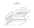
- Fig. 1 is a perspective view illustrating a structure of a discharge cell in the related art PDP.
- the discharge cell of the PDP includes a sustain electrode pair 12A and 12B formed on an upper substrate 10 and a data electrode 20 formed on a lower substrate 18.
- the sustain electrode pair 12A and 12B each have a double-layer structure of a transparent electrode and a metal electrode.
- the sustain electrode pair 12A and 12B are divided into a scan electrode 12A for supplying a scan signal for address discharge and a sustain signal for sustain discharge, and a sustain electrode 12B for supplying a sustain signal alternating with the scan electrode 12A.
- the data electrode 20 is formed to intersect with the sustain electrode pair 12A and 12B, and supplies a data signal for address discharge.
- An upper dielectric layer 14 and a protective layer 16 are stacked on the upper substrate 10 on which the sustain electrode pair 12A and 12B are formed.
- the upper dielectric layer 14 and a lower dielectric layer 22 accumulate charges generated by discharge.
- the protective layer 16 prevents damage of the upper dielectric layer 14 by sputtering of pl asma particles during the discharge and increases an emission efficiency of secondary electrons. Accordingly, a driving voltage applied from the outside can be lowered by the upper and lower dielectric layers 14 and 22 and the protective layer 16.
- the lower dielectric layer 22 is formed on the lower substrate 18 where the data electrode 20 is formed.
- a barrier rib 24 is formed on the lower dielectric layer 22 with the data electrode 20 interposed therebetween.
- a phosphor layer 26 is formed on surfaces of the lower dielectric layer 22 and the barrier rib 24.
- the phosphor layer 26 includes a red (R) phosphor layer, a green (G) phosphor layer and a blue (B) phosphor layer.
- the phosphor layer 26 separates a discharge space to thereby prevent ultraviolet ray s generated by gas discharge in the discharge space from leaking toward its neighboring discharge space.
- the phosphor layer 26 is radiated by ultraviolet rays generated by gas discharge to thereby emit R, G and B visible rays.
- the discharge space is char ged with inert gases for gas discharge.
- the PDP can also include a plurality of discharge cells arranged in matrix form.
- a discharge cell is selected by address discharge of the data electrode 20 and the scan electrode 12A, and the selected discharge cell maintains discharge by sustain discharge by the sustain electrode pair 12A and 12B.
- the phosphor 26 is radiated by ultraviolet rays generated in the selected discharge cell and thereby emits R, G and B visible rays. Accordingly, the discharge cell represents a gray scale by adjusting a sustain discharge period, namely the frequency of a sustain discharge according to video data. Combination of 3 discharge cells respectively coated with R, G and B phosphor layers 26 enables representation of a color of one pixel.
- an ADS (address and display separated) driving method that drives a PDP in such a way that an address period is separated from a display period, namely, a sustain period.
- the ADS driving method divides one frame 1F into a plurality of sub-fields SF1 through SF8 corresponding to respective bits of video data.
- the sub - fields each is then subdivided into a reset period RPD for initialization of a discharge cell, an address period APD for selection of a discharge cell, and a sustain period SPD for maintenance of the selected discharge cell 's discharge.
- Different weights are given to sub-fields during the sustain period SPD, and the sustain periods are combined according to video data, whereby a gray scale is represented.
- the PDP uses an error diffusing method so as to enhance an gray scale expression.
- the error diffusing method calculates quantization error data of digital video data by using the Floyd-Steinberg error diffusing filter, applies different weights according to the calculated quantization error data and then diffuses the error to neighboring pixels.
- the error diffusing method gives a weight 1/16 to a pixel P1 neighboring the current pixel P5, a weight 5/16 to a pixel P2, a weight 3/16 to a pixel P3, and a weight 7/16 to a pixel P4, and thereby calculates error diffusion coefficients about the respective pixels P1 through P4. Thereafter, the error diffusing method generates a carry signal by adding the calculated error diffusion coefficients and then obtains a current pixel value by adding the carry signal to a current pixel value P5.
- the effort diffusing method has a problem in that error diffusion coefficients (that is, weights) about neighboring pixels are constantly set and repeated at every line and at every frame, whereby an error diffusing pattern is generated.
- error diffusion coefficients that is, weights
- the prior art error diffusing method has a limitation in a gray scale expression of video data.
- the present invention is directed to an apparatus and method for processing a gray scale in a display device that substantially obviates one or more problems due to limitations and disadvantages of the related art.
- An object of the present invention is to provide a gray scale processing apparatus and method capable of increasing a gray scale expression and minimizing an error diffusion noise.
- a method for processing a gray scale in a display device includes the steps of: randomly error -diffusing a video data by using random coefficients; and dithering the error-diffused video data by using average picture level (APL) mask.
- APL average picture level
- an apparatus for processing a gray scale in a display device includes: a random error diffusing block for randomly error - diffusing a video data by using random coefficients; and a dithering block for dithering the error -diffused video data by using average picture level (APL) mask.
- APL average picture level
- Fig. 1 is a perspective view illustrating a structure of a discharge cell in the related art PDP
- Fig. 2 is an exemplary view illustrating a structure of sub-fields in one frame
- Fig. 3 is a view illustrating the related art error diffusion method
- Fig. 4 is a schematic block diagram illustrating a gray scale processor of a PDP according to an embodiment of the present invention
- Fig. 5 is a block diagram illustrating a detailed structure of an error diffusing/dithering block shown in Fig. 4;
- Fig. 6 is a diagram illustrating a bit structure of video data outputted from a gamma corrector shown in Fig. 4;
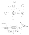
- Fig. 7 is a diagram illustrating an error diffusion method in an random error diffuser shown in Fig. 5;
- Fig. 8 is a block diagram illustrating a structure of a dithering block shown in Fig. 5;
- Fig. 9 is a diagram illustrating a dithering mask pattern stored in a dithering mask table shown in Fig. 8.
- Fig. 10 is a diagram illustrating a method in which a gray scale expression is inc reased by the error diffusing/dithering block shown in Fig. 4.
- Fig. 4 is a schematic block diagram illustrating a gray scale processor of a PDP according to an embodiment of the present invention.
- the gray scale processor includes a gamma corrector 30, an error diffusing/dithering block 32, a sub-field mapping block 34 and a data driving block 36, which are connected between a video data input line and a PDP 38.
- Digital video data that was gamma-corrected to be adapted to a luminance characteristic of a cathode ray tube (CRT), namely pixel values that is to be provided to respective pixels, is inputted to the gamma corrector 30 from the outside.
- the gamma corrector 30 inversely gamma-corrects the inputted pixel values to thereby cause a linear luminance characteristic according to a pixel value to be linear.
- the gamma collector 30 outputs an inversely gamma-corrected pixel value corresponding to an input pixel value by using a preset look-up table so that a luminance characteristic according to a pixel value follows a 2.2 gamma curve.
- each of pixel values outputted from the comma corrector 30 is composed of an integer part and a decimal part.
- the gamma corrector 30 outputs a 16-bit inversely gamma-corrected pixel value composed of an 8-bit integer part and an 8-bit decimal part.
- the 8-bit decimal part is composed of upper part bits used for random error diffusing and lower part bits used for random dithering.
- more upper part bits and more lower part bits can be used.
- the error diffusing/dithering block 32 corrects each of the pixel values outputted from the gamma corrector 30 by error diffusing and dithering to thereby increase a gray scale expression and decrease the number of bits of pixel values. That is, the error diffusing/dithering block 32 error-diffuses the inversely gamma-corrected pixel values by using a first random coefficient, and then dithers the error-diffused pixel values by using a second random coefficient.
- the error -diffusion of the inversely gamma corrected pixel values through the first random coefficient generates a carry signal. The so -generated carry signal is added to upper part bits of a decimal part of a pixel value prior to a dithering process.
- the addition of the first and seco nd random coefficients in the error diffusing and dithering can prevent an error diffusion pattern caused by a constant error diffusion coefficient from occurring.
- the error diffusing/dithering block 32 performs a random error diffusing by using lower part bits of a decimal part of a pixel value used in a dithering operation, thereby enabling rather more gray scale expression through subdivision of a step interval between dithering patterns. An operation of the error diffusing/dithering block 32 will be described in detail later.
- the sub-field mapping block 34 maps each of pixel values outputted from the error diffusing/dithering block 32 to a predetermined sub-field pattern.
- the data diving block 36 latches input data that is divided on a bit basis according to a sub-field pattern outputted from the sub-field mapping block 34, and provides the latched data to a corresponding data electrode of the PDP 38 on a line basis during the period while one horizontal line is driven.
- the PDP 38 includes a data electrode and sustain electrodes (for example, scan electrode and sustain electrode) that intersect the data electrode with a discharge space being interposed therebetween. Accordingly, a discharge cell having the discharge space corresponding to a sub -pixel is formed at an intersection between the data electrode and the sustain electrodes.
- a data electrode and sustain electrodes for example, scan electrode and sustain electrode
- the PDP 38 selects discharge cells which is to be turn -on by address discharge according to data provided from the data driving block 36 to a data electrode.
- the PDP 38 makes the selected discharge cells maintain discharge during the sustain period of each subfiled by driving the sustain electrodes.
- sin ce the number of sub-fields constituting one frame is decreased as many as the number of bits of video data is decreased by the error diffusing/dithering block 32, a sufficient address period can be obtained, whereby the PDP 38 can be driven only by a sing le-scan method.
- Fig. 5 is a block diagram illustrating a detailed structure of the error diffusing/dithering block shown in Fig. 4.
- the error diffusing/dithering block 32 includes a random generator 43, an average picture level (APL) operation block 45, a random error diffusing block 40 and a dithering block 50.
- APL operation block 45 may either be included in the error diffusing/dithering block 32 or may be separately equipped at the outside.
- the random generator 43 generates random coefficients R1 and R2 and provides the generated random coefficients to the random error diffusing block 40. These random coefficients R1 and R2 are used for random error diffusing.
- the random error diffusing block 40 generates a carry signal by adding an error diffusion coefficient, which is calculated by giving predetermined different weights depending on video data outputted from the gamma corrector 30, a current pixel value and a random coefficient. As shown in Fig. 7, by using pixels A and B neighboring a current pixel D and pixels A and C neighboring a current pixel E, respective carry values of the current pixels D and E are expressed as the following Equation (1).
- 'Random coff.a' and 'Random coff.a' respectively represent the random coefficients R1 and R2
- 'A', 'B' and 'C' respectively represent random error diffusion values of the pixels A, B and C
- 'ch1_cur_err' and 'ch2_cur_err' respectively represent the current pixel values of the pixels D and E.
- the carry signal is generated by adding respective error diffusion coefficients, which are calculated by respectively multiplying random error diffusion values of neighboring pixels by different weights, random coefficient R, and current pixel value.
- a random error diffusion value of the pixel D is calculated by multiplying lower 5 bits of a decimal part of 'A' by a weight 7 and multiplying lower 5 bits of a decimal part of 'B' by a weight 5 and then adding the two resulting values, as shown in Equation (1).
- a carry signal of the pixel D is calculated by adding the random error diffusion value, the first random coefficient R1 and the current pixel value of the pixel D.
- an uppermost bit of the lower 5 bits generates a carry signal '0' or '1'.
- the so-generated carry signal added to an upper 3 bits of a decimal part of 'D', whereby a random error diffusion value of 11 bits (8 bits of a integer part + 3 bits of a decimal part) is outputted to the dithering block 50.
- the dithering block 50 dithers the random error diffusion value from the random error diffusing block 40 by using an APL mask selected according to a dithering mask pattern and an APL value calculated by the APL operation block 45, and thereby outputs a pixel value whose bit number is decreased to the sub-field mapping block 34.
- the dithering block 50 includes a dithering mask controller 52, a dithering mask table 54, an APL mask table 56, an exclusive OR (XOR) gate 57 and an adder 58 as shown in Fig. 8.
- the dithering mask controller 52 counts a vertical synchronization signal (V) received from an outside controller (not shown) to thereby indicate a corresponding frame out of 4 frames 1F through 4F, and counts a horizontal synchronization signal (H) and a pixel clock signal (P) to thereby indicate horizontal and vertical lines (i.e. a cell position) in the corresponding frame.
- V vertical synchronization signal
- H horizontal synchronization signal
- P pixel clock signal
- the dithering mask table 54 stores dithering mask patterns different from one another by gray scales and frames. For example, as shown in Fig. 9, dithering mask patterns, each of which has the size of 4x4 cells, are classified by 8 gray scales of 0 through 7/8 corresponding to upper 3 bits of a decimal part of a random error diffusion value, and each of the resulting 8 dithering mask patterns is reclassified by the 4 frames 1F through 4F, whereby a total of 32 dithering mask patterns are stored in the dithering mask table 54. Although dithering mask patterns set to '0' or '1' in the frames 2F and 3F are not shown in Fig.
- dithering mask patterns which are set to '0' or '1' in such a way as that of the frames 1F and 4F, are included in the frames 2F and 3F.
- the number of cells set to a dither value '1' increases in order of 0, 2, 4, 6, 8, 10, 12 and 14.
- positions of cells set to a dithering value "1" var y by the 4 frames 1F through 4F. Positions of dithering values "1s" in respective dithering mask patterns may vary depending on designer 's requests.
- positions of on -cells corresponding to dithering values '1s' can be controlled in time and space.
- positions of dithering values '1s' in dithering mask patterns vary by gray scales and frames, whereby an error diffusion noise caused by repetition of a constant dithering mask pattern, such as a lattice noise, can be decreased.
- dithering mask patterns different from one another by R (red), G (green) and B (blue) pixels may be stored in the dithering mask table 54 so as to further decrease a noise caused by a dither mask pattern.
- the dithering mask table 54 storing the aforementioned dithering mask patterns receives a random error diffusion value, for example, upper 3 bits of a decimal part out of a pixel value of 11 bits (8 bits of an integer part + 3 bits of a decimal part) from the random error diffusing block 40 to then select a dithering mask pattern corresponding to a gray scale of the upper 3 bits.
- a random error diffusion value for example, upper 3 bits of a decimal part out of a pixel value of 11 bits (8 bits of an integer part + 3 bits of a decimal part) from the random error diffusing block 40 to then select a dithering mask pattern corresponding to a gray scale of the upper 3 bits.
- the dithering mask table 54 selects a dithering mask pattern of a gray scale corresponding to the received upper 3 bits out of the dithering mask patterns shown in Fig. 9. Thereafter, the dithering mask table 54 selects a dithering value D corresponding to a position of a frame and a cell indicated by the dithering mask controller 52 out of the selected dithering mask pattern to then output the selected dithering value D to the XOR gate 57. Meanwhile, an APL mask selected out of the APL mask table 56 is inputted to the XOR gate 57.
- At least one or more APL masks are stored in the APL mask table 56 so that one of the stored APL mask is selected according to an APL value outputted from the APL operation block 45.
- APL values are within the range of 0 through 100
- respective APL masks are set and stored in the APL mask table 56 so that APL values 0 through 25 correspond to an APL mask 1
- APL values 26 through 50 correspond to an APL mask 2
- APL values 51 through 75 correspond to an APL mask 3
- APL values 76 through 100 correspond to an APL mask 4.
- APL mask values are set to be proportional to the APL values. That is, according as an APL value increases, more '1s' are set in a corresponding APL mask.
- a dithering mask selected out of the dithering mask table 54 and an APL mask value are inputted to the XOR gate 57, and are then XORed in the XOR gate 57.
- the XORed value is inputted to the adder 58.
- the adder 58 adds the XORed value outputted from the XOR gate 56 and the random error diffusion value outputted from the random error diffusing block 40 to then provide the added value to the sub-field mapping block 34.
- the gray scale processing apparatus and method according to the present invention randomly error-diffuses a pixel value whose bit number is extended from 8 to 16 by inverse gamma correction, and performs dithering by using APL mask values different from one another according to APL values, and thereby can remove a noise such as a pattern caused by error diffusion.
- the gray scale processing apparatus and method subdivides gray scales between basic gray scales by performing at the dithering block 50 a dithering by using the dithering mask patterns shown in Fig. 9, and thereby can increase the number of expressible gray scales. This is possible by combination of data '1s' that are dispersed in space and time, such as the dithering mask patterns shown in Fig. 9.
- the present invention represents 256 basic gray scales by using an 8 -bit pixel value finally generated by an error diffusing and dithering operation. If 8 gray scales are represented by the dithering and 32 gray scales are represented by the random error diffusing as shown in Fig. 10, a total of 256 gray scales can be represented.
- the gray scale processing apparatus and method according to the present invention randomly error-diffuses video data by using random coefficients and performs a dithering by using different APL mask values according to APL values, and thereby can enhance a gray scale expression and minimize an error diffusion noise.
Landscapes
- Engineering & Computer Science (AREA)
- Physics & Mathematics (AREA)
- Computer Hardware Design (AREA)
- General Physics & Mathematics (AREA)
- Theoretical Computer Science (AREA)
- Multimedia (AREA)
- Signal Processing (AREA)
- Power Engineering (AREA)
- Plasma & Fusion (AREA)
- Control Of Indicators Other Than Cathode Ray Tubes (AREA)
- Control Of Gas Discharge Display Tubes (AREA)
- Image Processing (AREA)
Abstract
Description
Claims (22)
- A method for processing a gray scale in a display device which displays video data, the method comprising the s teps of:randomly error-diffusing the video data by using random coefficients; anddithering the error-diffused video data by using average picture level (APL) mask.
- The method according to claim 1, wherein the video data is data that is inversely gamma-corrected and has an integer part and a decimal part.
- The method according to claim 2, wherein the decimal part comprises upper part bits and lower part bits, the upper part bits being used for the dithering, the lower part bits being used for the random error diffusing.
- The method according to claim 1, wherein the APL mask comprises at least one or more masks corresponding to APL values.
- The method according to claim 1, wherein the APL mask has mask values proportional to APL values.
- The method according to claim 1, wherein the randomly error-diffusing step comprises the steps of:generating a carry signal by adding error diffusion coefficients, a current pixel value and the random coefficient, the error diffusion coefficients being obtain ed by respectively giving predetermined different weights to error diffusion values of a neighboring pixel of the video data; andadding the carry signal to upper part bits of the current pixel and outputting the resulting value.
- The method according to claim 6, wherein the steps are identically performed with respect to respective pixels of the video data.
- The method according to claim 1, wherein the dithering step comprises the steps of:selecting a dithering mask pattern corresponding to the random error diffusion value;XORing a dithering value of the selected dithering mask pattern and the APL mask; andadding the XORed value to the random error diffusing value and outputting the resulting value.
- The method according to claim 8, wherein the selected dithering mask pattern is outputted depending on combination of a vertical synchronization signal, a horizontal synchronization signal and a pixel clock signal.
- The method according to claim 8, wherein the dithering mask pattern is selected by a gray scale value corresponding to upper part bits of a decimal part of the random error diffusion value.
- The method according to claim 8, wherein the dithering mask pattern is set by gray scales and frames.
- An apparatus for processing a gray scale in a display device which displays video data, the apparatus comprising:a random error diffusing block for randomly error -diffusing the video data by using random coefficients; anda dithering block for dithering the error -diffused video data by using average picture level (APL) mask.
- The apparatus according to claim 12, further comprising a gamma corrector for inversely gamma -correcting the video data to thereby cause the video data to have an integer part and a decimal part.
- The apparatus according to claim 13, wherein the decimal part comprises upper part bits and lower part bits, the upper part bits being used for the dithering, the lower part bits being used for the random error diffusing.
- The apparatus according to claim 12, furthe r comprising a random generator for generating a random coefficient and providing the random coefficient to the random error diffusing block.
- The apparatus according to claim 12, further comprising an APL operation block for calculating an APL value o f the video data.
- The apparatus according to claim 12, wherein the random error diffusing block generates a carry signal by adding error diffusion coefficients, a current pixel value and the random coefficient, the error diffusion coefficients being obtained by respectively giving predetermined different weights to error diffusion values of a neighboring pixel of the video data, and the random error diffusing block adds the carry signal to upper part bits of the current pixel and outputs the resulting value.
- The apparatus according to claim 12, wherein the dithering block comprises:a dithering mask table for selecting a dithering mask pattern corresponding to the random error diffusion value;an XOR gate for XORing a dithering value of the selecte d dithering mask pattern and the APL mask; andan adder for adding the XORed value to the random error diffusing value.
- The apparatus according to claim 18, wherein the selected dithering mask pattern is outputted according to combination of a vertical synchronization signal, a horizontal synchronization signal and a pixel clock signal.
- The apparatus according to claim 18, wherein the dithering mask pattern is selected by a gray scale value corresponding to upper part bits of a decimal part of the random error diffusion value.
- The apparatus according to claim 18, wherein the dithering mask pattern is set by gray scales and frames.
- The apparatus according to claim 12, wherein the dithering block selects one of APL masks depending on APL va lues outputted from the APL operation block and uses the selected one for dithering.
Applications Claiming Priority (2)
| Application Number | Priority Date | Filing Date | Title |
|---|---|---|---|
| KR10-2003-0084401A KR100512104B1 (en) | 2003-11-26 | 2003-11-26 | Method for processing a gray scale in a display device and apparatus using the same |
| KR2003084401 | 2003-11-26 |
Publications (2)
| Publication Number | Publication Date |
|---|---|
| EP1536632A2 true EP1536632A2 (en) | 2005-06-01 |
| EP1536632A3 EP1536632A3 (en) | 2008-04-23 |
Family
ID=34464748
Family Applications (1)
| Application Number | Title | Priority Date | Filing Date |
|---|---|---|---|
| EP04106038A Withdrawn EP1536632A3 (en) | 2003-11-26 | 2004-11-24 | Apparatus and method for processing gray scale in display device |
Country Status (5)
| Country | Link |
|---|---|
| US (1) | US7385567B2 (en) |
| EP (1) | EP1536632A3 (en) |
| JP (1) | JP2005157367A (en) |
| KR (1) | KR100512104B1 (en) |
| CN (1) | CN1622154A (en) |
Cited By (3)
| Publication number | Priority date | Publication date | Assignee | Title |
|---|---|---|---|---|
| EP1914706A3 (en) * | 2006-10-18 | 2009-01-07 | Samsung Electronics Co., Ltd. | Apparatus and method for driving self-emission display panel |
| WO2009102618A1 (en) * | 2008-02-13 | 2009-08-20 | Qualcomm Mems Technologies, Inc. | Multi-level stochastic dithering with noise mitigation via sequential template averaging |
| CN102595155A (en) * | 2011-01-10 | 2012-07-18 | 奇美电子股份有限公司 | Driving method and driving device for three-dimensional display |
Families Citing this family (11)
| Publication number | Priority date | Publication date | Assignee | Title |
|---|---|---|---|---|
| US8934702B2 (en) | 2003-12-02 | 2015-01-13 | The Boeing Company | System and method for determining cumulative tow gap width |
| KR100499102B1 (en) * | 2003-12-15 | 2005-07-01 | 엘지전자 주식회사 | Apparatus and Method of Driving Plasma Display Panel |
| EP1770682B1 (en) * | 2005-09-28 | 2011-04-27 | Sony Ericsson Mobile Communications AB | Method for enhancing colour resolution and device exploiting the method |
| CN101595734A (en) * | 2007-01-16 | 2009-12-02 | 汤姆逊许可证公司 | Systems and methods for mitigating artifacts in images |
| KR20090116166A (en) * | 2008-05-06 | 2009-11-11 | 삼성에스디아이 주식회사 | Method and apparatus for processing video data of plasma display panel |
| JP5526628B2 (en) * | 2009-07-03 | 2014-06-18 | ソニー株式会社 | Video display device and video display system |
| CN101950528B (en) * | 2009-12-31 | 2012-06-27 | 四川虹欧显示器件有限公司 | Linear adjustment method of gray scales of PDP (Plasma Display Panel) |
| KR20130087927A (en) * | 2012-01-30 | 2013-08-07 | 삼성디스플레이 주식회사 | Apparatus for processing image signal and method thereof |
| KR102452640B1 (en) * | 2015-10-21 | 2022-10-11 | 삼성전자주식회사 | Display apparatus and control method thereof |
| KR101696609B1 (en) * | 2015-10-26 | 2017-01-16 | 주식회사 홍익기술 | De Mura Method of Display Panel and De-Mura Module |
| CN113542710B (en) * | 2021-09-15 | 2022-02-22 | 广州匠芯创科技有限公司 | Image processing method, system and medium based on error diffusion Dither algorithm |
Family Cites Families (13)
| Publication number | Priority date | Publication date | Assignee | Title |
|---|---|---|---|---|
| JP2970336B2 (en) * | 1993-08-26 | 1999-11-02 | 株式会社富士通ゼネラル | PDP drive circuit |
| JP3354741B2 (en) * | 1995-04-17 | 2002-12-09 | 富士通株式会社 | Halftone display method and halftone display device |
| JP4016493B2 (en) * | 1998-08-05 | 2007-12-05 | 三菱電機株式会社 | Display device and multi-gradation circuit thereof |
| GB9925054D0 (en) * | 1999-10-23 | 1999-12-22 | Koninkl Philips Electronics Nv | Display arrangement |
| US7460275B2 (en) * | 1999-12-02 | 2008-12-02 | Texas Instruments Incorporated | Odd/even error diffusion filter |
| JP2002023693A (en) * | 2000-07-06 | 2002-01-23 | Pioneer Electronic Corp | Driving method for plasma display device |
| US6791516B2 (en) * | 2001-01-18 | 2004-09-14 | Lg Electronics Inc. | Method and apparatus for providing a gray level in a plasma display panel |
| JP2002232713A (en) * | 2001-02-06 | 2002-08-16 | Mitsubishi Electric Corp | Image processing apparatus and image processing method |
| JP2003015588A (en) * | 2001-06-28 | 2003-01-17 | Pioneer Electronic Corp | Display device |
| KR100438918B1 (en) * | 2001-12-08 | 2004-07-03 | 엘지전자 주식회사 | Method and apparatus for driving plasma display panel |
| JP4064268B2 (en) * | 2002-04-10 | 2008-03-19 | パイオニア株式会社 | Display device and display method using subfield method |
| JP2003330420A (en) * | 2002-05-16 | 2003-11-19 | Semiconductor Energy Lab Co Ltd | Method of driving light emitting device |
| US7043089B2 (en) * | 2003-02-27 | 2006-05-09 | Hewlett-Packard Development Company, L.P. | Overflow error diffusion |
-
2003
- 2003-11-26 KR KR10-2003-0084401A patent/KR100512104B1/en not_active Expired - Fee Related
-
2004
- 2004-11-16 US US10/988,547 patent/US7385567B2/en active Active
- 2004-11-22 JP JP2004337191A patent/JP2005157367A/en active Pending
- 2004-11-23 CN CNA2004100889981A patent/CN1622154A/en active Pending
- 2004-11-24 EP EP04106038A patent/EP1536632A3/en not_active Withdrawn
Cited By (7)
| Publication number | Priority date | Publication date | Assignee | Title |
|---|---|---|---|---|
| EP1914706A3 (en) * | 2006-10-18 | 2009-01-07 | Samsung Electronics Co., Ltd. | Apparatus and method for driving self-emission display panel |
| CN101165757B (en) * | 2006-10-18 | 2012-03-14 | 三星电子株式会社 | Apparatus and method for driving self-emission display panel |
| WO2009102618A1 (en) * | 2008-02-13 | 2009-08-20 | Qualcomm Mems Technologies, Inc. | Multi-level stochastic dithering with noise mitigation via sequential template averaging |
| US8451298B2 (en) | 2008-02-13 | 2013-05-28 | Qualcomm Mems Technologies, Inc. | Multi-level stochastic dithering with noise mitigation via sequential template averaging |
| RU2511574C2 (en) * | 2008-02-13 | 2014-04-10 | Квалкомм Мемс Текнолоджис, Инк. | Multilevel stochastic pseudo mixing with noise suppression by successive averaging with help of patterns |
| CN102595155A (en) * | 2011-01-10 | 2012-07-18 | 奇美电子股份有限公司 | Driving method and driving device for three-dimensional display |
| CN102595155B (en) * | 2011-01-10 | 2014-11-19 | 群创光电股份有限公司 | Driving method and driving device for three-dimensional display |
Also Published As
| Publication number | Publication date |
|---|---|
| US7385567B2 (en) | 2008-06-10 |
| CN1622154A (en) | 2005-06-01 |
| JP2005157367A (en) | 2005-06-16 |
| EP1536632A3 (en) | 2008-04-23 |
| US20050110714A1 (en) | 2005-05-26 |
| KR20050050773A (en) | 2005-06-01 |
| KR100512104B1 (en) | 2005-09-05 |
Similar Documents
| Publication | Publication Date | Title |
|---|---|---|
| KR100499102B1 (en) | Apparatus and Method of Driving Plasma Display Panel | |
| EP1536400B1 (en) | Method for processing a gray level in a plasma display panel and apparatus using the same | |
| US7385567B2 (en) | Apparatus and method for processing gray scale in display device | |
| KR100552908B1 (en) | Driving method and driving apparatus of plasma display panel | |
| JP4925576B2 (en) | Apparatus and method for driving plasma display panel | |
| JP3006363B2 (en) | PDP drive method | |
| JP4192168B2 (en) | Plasma display device and image processing method thereof | |
| US20050088373A1 (en) | Gray scale expression method in plasma display panel and driving apparatus for plasma display panel | |
| US20050134615A1 (en) | Method and apparatus for driving plasma display panel | |
| KR100570968B1 (en) | Method and apparatus for processing video data of plasma display panel | |
| JP2005128544A (en) | Method and system for decreasing afterimage of plasma display panel | |
| KR100512105B1 (en) | Method for processing a gray scale in a display device and apparatus using the same | |
| KR100505989B1 (en) | Method And Apparatus of Processing Video Data For Plasma Display Panel | |
| KR100593069B1 (en) | Image processing apparatus and method of plasma display panel | |
| KR20050101442A (en) | Image processing apparatus for plasma display panel | |
| JP2005128550A (en) | Plasma display panel and driving apparatus and driving method thereof | |
| KR100639033B1 (en) | Subfield Mapping Apparatus and Method for Reducing Halftone Noise | |
| KR20060083046A (en) | Driving apparatus and method of plasma display panel | |
| JP2005326635A (en) | Driving method for display panel and display device |
Legal Events
| Date | Code | Title | Description |
|---|---|---|---|
| PUAI | Public reference made under article 153(3) epc to a published international application that has entered the european phase |
Free format text: ORIGINAL CODE: 0009012 |
|
| AK | Designated contracting states |
Kind code of ref document: A2 Designated state(s): AT BE BG CH CY CZ DE DK EE ES FI FR GB GR HU IE IS IT LI LU MC NL PL PT RO SE SI SK TR |
|
| AX | Request for extension of the european patent |
Extension state: AL HR LT LV MK YU |
|
| PUAL | Search report despatched |
Free format text: ORIGINAL CODE: 0009013 |
|
| AK | Designated contracting states |
Kind code of ref document: A3 Designated state(s): AT BE BG CH CY CZ DE DK EE ES FI FR GB GR HU IE IS IT LI LU MC NL PL PT RO SE SI SK TR |
|
| AX | Request for extension of the european patent |
Extension state: AL HR LT LV MK YU |
|
| 17P | Request for examination filed |
Effective date: 20081010 |
|
| AKX | Designation fees paid |
Designated state(s): DE FR NL |
|
| 17Q | First examination report despatched |
Effective date: 20090609 |
|
| STAA | Information on the status of an ep patent application or granted ep patent |
Free format text: STATUS: THE APPLICATION IS DEEMED TO BE WITHDRAWN |
|
| 18D | Application deemed to be withdrawn |
Effective date: 20091020 |