EP1536620A2 - Enregistrement d'erreurs pour des appels - Google Patents
Enregistrement d'erreurs pour des appels Download PDFInfo
- Publication number
- EP1536620A2 EP1536620A2 EP04300811A EP04300811A EP1536620A2 EP 1536620 A2 EP1536620 A2 EP 1536620A2 EP 04300811 A EP04300811 A EP 04300811A EP 04300811 A EP04300811 A EP 04300811A EP 1536620 A2 EP1536620 A2 EP 1536620A2
- Authority
- EP
- European Patent Office
- Prior art keywords
- failure
- log
- type
- call
- function
- Prior art date
- Legal status (The legal status is an assumption and is not a legal conclusion. Google has not performed a legal analysis and makes no representation as to the accuracy of the status listed.)
- Withdrawn
Links
Images


Classifications
-
- H—ELECTRICITY
- H04—ELECTRIC COMMUNICATION TECHNIQUE
- H04M—TELEPHONIC COMMUNICATION
- H04M3/00—Automatic or semi-automatic exchanges
- H04M3/22—Arrangements for supervision, monitoring or testing
-
- H—ELECTRICITY
- H04—ELECTRIC COMMUNICATION TECHNIQUE
- H04M—TELEPHONIC COMMUNICATION
- H04M3/00—Automatic or semi-automatic exchanges
- H04M3/08—Indicating faults in circuits or apparatus
-
- H—ELECTRICITY
- H04—ELECTRIC COMMUNICATION TECHNIQUE
- H04M—TELEPHONIC COMMUNICATION
- H04M3/00—Automatic or semi-automatic exchanges
- H04M3/22—Arrangements for supervision, monitoring or testing
- H04M3/2218—Call detail recording
-
- H—ELECTRICITY
- H04—ELECTRIC COMMUNICATION TECHNIQUE
- H04M—TELEPHONIC COMMUNICATION
- H04M3/00—Automatic or semi-automatic exchanges
- H04M3/08—Indicating faults in circuits or apparatus
- H04M3/085—Fault locating arrangements
-
- H—ELECTRICITY
- H04—ELECTRIC COMMUNICATION TECHNIQUE
- H04M—TELEPHONIC COMMUNICATION
- H04M3/00—Automatic or semi-automatic exchanges
- H04M3/22—Arrangements for supervision, monitoring or testing
- H04M3/2209—Arrangements for supervision, monitoring or testing for lines also used for data transmission
-
- H—ELECTRICITY
- H04—ELECTRIC COMMUNICATION TECHNIQUE
- H04M—TELEPHONIC COMMUNICATION
- H04M3/00—Automatic or semi-automatic exchanges
- H04M3/22—Arrangements for supervision, monitoring or testing
- H04M3/2254—Arrangements for supervision, monitoring or testing in networks
-
- H—ELECTRICITY
- H04—ELECTRIC COMMUNICATION TECHNIQUE
- H04M—TELEPHONIC COMMUNICATION
- H04M3/00—Automatic or semi-automatic exchanges
- H04M3/22—Arrangements for supervision, monitoring or testing
- H04M3/36—Statistical metering, e.g. recording occasions when traffic exceeds capacity of trunks
Definitions
- This invention relates in general to the field of telecommunication switching equipment and in particular to an improved call failure recording.
- Data transmission is always subject to error or failures due to the transmission medium errors, signal integrity problems and/or failure of the equipment along the transmission path. Since the ability to reliably transmit data is of utmost importance the transmission systems are equipped with fault managers, which detect, locate and correct the faults so that the service disruptions are minimized.
- fault logs Current fault managers generate a fault report whenever a fault is detected anywhere in the data transmission system, identifying the location, type and sometimes providing other information with respect to the nature of the fault. These reports are called fault logs.
- the fault manager then processes the logs; the basic processing includes sorting, storage, retrieval and other processing functions necessary to analyze the logs for isolating the cause of the fault.
- a fault in the network may cause many active calls to clear for the same reason, generating a log for each affected call. Also, if a call attempt fails, new failure logs due to the same problem will be generated each time the originator re-attempts to set-up the call. In some cases, almost thousands of identical failure logs, related to the same fault could be generated. Still further, as the fault rate increases with the number of nodes, the traffic generated by fault also increases. In turn, fault propagation may further generate additional events.
- the information in the failure logs needs to be processed sequentially. Therefore, both the managed system and the management system send and respectively process the failure logs in time sequence, and the failure records must provide this timing information.
- Another object of the invention is to provide a call failure recording method that reduces substantially the number of failure records stored for enabling efficient processing of the information contained in the logs, while maintaining the integrity (sequence) of fault information.
- the invention provides a method for recording call failure information in a data transmission system, comprising: generating a first failure log in response to a failure event, the first failure log including a failure type and a first time stamp and placing the first failure log in a queue; formulating an identifier for the first failure log based on the failure type; and creating a log record for the first failure log and storing the log record in a log record storage.
- the invention also provides a device for recording call failure information in a data transmission system, comprising: means for generating a failure log in response to a failure event, the failure log including a time stamp; a log queue for temporarily receiving the failure log; means for formulating an identifier for the failure log based on a failure type of the event that generated the failure log; means for creating a log record for the failure log, which includes the identifier, and a log record storage for storing the log record.
- One of the advantages of the invention is that it uses less storage space then in the prior art approaches, making the use of the proposed method more cost-effective. Furthermore, since the fault information consumes less space than in the prior art methods, the fault information can be sorted, retrieved and processed faster.
- a further advantage of the invention is that all failure logs generated by the same network fault point to that fault, so that fault isolation is significantly simplified. Configuration is supported to allow users to refine fault log investigation such that each failure generates different failure logs.
- the present invention uses event correlation techniques and some call parameters (such as the cause code, called/calling party, physical location) to group distinct failure logs triggered by the same event, thereby shortening the failure log queues into a form more readily managed by the network operator.
- Some call parameters such as the cause code, called/calling party, physical location
- the time between faults and repairs is importantly reduced and also automatic correction of some diagnosed problems becomes feasible.
- a call will generate as many failure logs as there are points of failure in the network for that particular call. For example, if an attempted call from the source to the destination node fails at three distinct nodes, in the network, this will result in a detailed failure log being generated at each of the three nodes for the same call.
- Figures 1A and 1B provide two examples of failures and how the failure data is processed. The improvement to call failure recording according to the invention is described later, after description of Figure 2, which provides the main elements of the invention.
- Figure 1A illustrates a service provides network SPN connecting two end user nodes A and B .
- Provider's network has in this example nodes C, D, E and F connected as shown, where nodes C and F are in direct communication with a respective user node.
- node A source node
- CA call attempt
- node E creates a call failure log FL1 and stores it. End user A re-attempts the call to end user B, but the call attempt fails again at port P7, for the same reason.
- Node E creates a new call failure log FL2 .
- Node E will create a call failure log for each ensuing call attempts for an A-B connection.
- this second failure log and the next ones are stored at node E.
- failure logs may be generated at node C , being the originating point for the call from the perspective of the service provider network. It is apparent that a very large number of failure logs may be issued to indicate failures due to the same cause.
- the present invention is directed to detecting and handling the duplicate failure for reducing the memory space used by the duplicate records and most importantly for optimizing processing of the failure logs.
- node E determines that FL2 is a duplicate of FL1 and rather than storing FL2 as a separate record, updates the original log to indicate another failure with the same cause. All failure logs generated at node E due to the end of resources on port P7 will be recognized as duplicates and will update the failure log with the last call attempt information.
- Figure 1B shows an example that uses the same service provider network SPN but shows more end users attached to it.
- SPN service provider network
- node C can be configured such that only the first failure log FL1 is stored at node C .
- the associated failure log is determined to be a duplicate and rather than storing the log, the original failure log is updated.
- failure logs may be generated at any of the service provider "source nodes" where the failed call originated from the service provider network perspective (e.g. node D for a call H-B ). Duplication detection and handling may apply to these logs as well.
- Figure 1C is a block diagram of a part of a network for illustrating call failure information propagation for two failed attempts for the same call, when the service provider network attempts to avoid the failure using an alternative route.
- the call sequences are shown by numerals on the arrows that indicate the respective action.
- the source node is configured to originate a call to reach the destination node.
- the source node initiates a path set-up and the call is sent out over the signalling link connecting the source node with node A , as shown at 1 .
- Node A receives the call setup and forwards the call to node B , which has, in this example, the lowest path cost to the destination node, arrow 2 .
- Node B receives the call setup and tries to forward it to node D , but fails for whatever reason.
- a detailed call failure log is generated.
- the failure log ID, FL1 and the identity of the failure node are sent with a crankback message to node A , arrow 3 .
- Node A receives the crankback message, extracts the above information, stores it temporarily in a call event buffer, and sends again the call setup message towards the destination node, now through node C , as shown by arrow 4 .
- Node C receives the call setup and tries to forward it to node D , but fails for a link failure reason.
- a detailed call failure log is generated and the log ID FL2 , together with the node C identity are sent back to node A , as shown by arrow 5 .
- Node A receives this crankback message, extracts the node ID and the log ID, stores this information in the call event buffer and tries to find a further alternate path towards node D .
- node A retrieves the temporary stored information related to this call attempt, inserts it into a release message, and sends the release message containing B ( FL1 ) and C ( FL2 ) back to the source node, as shown by arrow 5 .
- the node identifier may be sent back to the source node also. This will allow a user to look at the call failure and have a picture of the path taken by the failed call.
- the source node receives the release message, extracts the failure information and stores the failure log into a source failure log queue for further processing.
- a further example is a fault on a soft permanent virtual circuit (SPVC).
- SPVC soft permanent virtual circuit
- This is a permanent virtual path that is initially configured through a management interface, but is connected using ATM signalling and routing.
- a single SPVC may fail e.g. due to a misconfigured destination. All re-tries of the same call will generate identical information for the detailed failure log and again in this case a single log with the failure information would be a better fit.
- FIG. 2 is a high-level block diagram of the call failure recording system according to an embodiment of the invention.
- the main elements of the system are a queue log 10 , a real-time processor 20 and a log record storage 30 .
- a failure record may comprise the calling party and called party address, the call request parameters, the ingress and egress ATM endpoints, a standard based release cause, a proprietary release cause, the call type, a time stamp (preferably milliseconds granularity) of the first failure of the respective type, a timestamp with the most recent failure of the respective type, and the number of failures of the same type.
- Some of the above information may not be available, depending on the stage of processing the call.
- filtering capability is also provided to output specific failure logs of interest.
- Processor 20 includes a log ID formulation unit 22, a duplicate log record detector 24 and a log record creation unit 26.
- Log ID formulation unit 22 provides a unique failure log ID based on the type of failure log. For example, logs in respect of failed active calls may have their failure reason (e.g. failure of a link) and failure point (e.g. a port at the end of the failed link) inspected to determine the failure log ID, or type. Logs pertaining to call attempts may have their failure reason, calling and called party fields inspected for establishing the ID.
- the resulting failure log ID is passed to the duplicate log record detection function DRDF 24 .
- DRDF 24 inspects log record storage 30 to determine if a log record having the same failure log ID already exists in the storage. If no, the failure log with its ID is passed to the log record creation unit 26 , where a new failure log record is created.
- a failure log record contains similar information with the original failure log such as call data (source and destination) and failure data (failure reason, failure point) and additionally it includes a counter, which counts the failure logs having the same failure log ID.
- a count may also be maintained to indicate the current number of faults for each proprietary clause. Both these counts are retrievable, and they constitute a convenient first place to look in a node to determine the cause of call failures occurring on the node. These statistics complement the existing call failure statistics available on the node (signalling statistics and routing statistics). It is to be noted that the parameters that determine whether two faults pertain to the same fault are user-configurable.
- node E that generated a number of failure logs for the same fault on port P7 places these failure logs in its failure log queue 10.
- the corresponding log record is time stamped and stored in log record storage 30.
- the record corresponding to FL1 is updated by adding the time stamp of FL2 in field 31 and increasing the count in field 32 by 1.
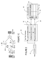
- Figures 3 and 4 show a respective block diagram of a variant of the log ID formulation unit 22 .
- Figure 3 shows an option where function unit 21 performs a preset function on selected portions of the failure log to generate the log ID.
- unit 21 may perform a checksum or other CRC-type function on the failure log.
- the portions of the failure log to be selected for this purpose depends on the type of failure, as illustrated by the filter 23 .
- the log type determination is performed in log type block 25 .
- the function block 21 shown in Figure 3 can be programmed in real time, with different detection criteria.
- the criteria may be applied to all attributes of the log, or to a subset of attributes, which are selected according to the log type.
- the criteria may for example be the failure reason and location (point), or other attributes such as the call type (call attempt, or active call), call configuration (from node A to node B ) as described above. Standard or proprietary failure causes may be used.
- Figure 4 illustrates an implementation using a plurality of function blocks 21-1 to 21-N , each for a specific type of failure log and each using a different combination of fields in the respective log to generate the log ID.
- Blocks 27 and 29 intuitively illustrate that the logs are separated (block 27 ) from the queue 10 according to their type, and re-combined (block 29 ) at the output of function blocks 21 .
- a network user may wish to see a single log with failure count for all failures with identical cause and diagnostics (e.g. switch congestion due to connection capacity reached).
- the network operator may want to capture every failure as an independent log as part of a particular problem investigation.
- the improved call failure recording according to the invention may be provided as a configurable feature.
- a call failure equivalence may be used to determine the criteria to log a call failure as an independent log, or as another occurrence of the same type of call failure. If the new log is an equivalent, then fields 31 and 32 are updated (the last failed call timestamp and the failure count).
Landscapes
- Engineering & Computer Science (AREA)
- Signal Processing (AREA)
- Telephonic Communication Services (AREA)
- Debugging And Monitoring (AREA)
Applications Claiming Priority (2)
| Application Number | Priority Date | Filing Date | Title |
|---|---|---|---|
| US720225 | 1985-04-05 | ||
| US10/720,225 US7502447B2 (en) | 2003-11-25 | 2003-11-25 | Call failure recording |
Publications (2)
| Publication Number | Publication Date |
|---|---|
| EP1536620A2 true EP1536620A2 (fr) | 2005-06-01 |
| EP1536620A3 EP1536620A3 (fr) | 2006-05-10 |
Family
ID=34465657
Family Applications (1)
| Application Number | Title | Priority Date | Filing Date |
|---|---|---|---|
| EP04300811A Withdrawn EP1536620A3 (fr) | 2003-11-25 | 2004-11-25 | Enregistrement d'erreurs pour des appels |
Country Status (2)
| Country | Link |
|---|---|
| US (1) | US7502447B2 (fr) |
| EP (1) | EP1536620A3 (fr) |
Families Citing this family (8)
| Publication number | Priority date | Publication date | Assignee | Title |
|---|---|---|---|---|
| US7457985B2 (en) * | 2005-09-09 | 2008-11-25 | International Business Machines Corporation | Method to detect errors in computer systems by using state tracking |
| US7924884B2 (en) * | 2005-12-20 | 2011-04-12 | Citrix Systems, Inc. | Performance logging using relative differentials and skip recording |
| CN101212783B (zh) * | 2006-12-28 | 2011-04-13 | 华为技术有限公司 | 子路由选择方法和设备 |
| US9705939B2 (en) | 2009-05-20 | 2017-07-11 | Peerless Network, Inc. | Self-healing inter-carrier network switch |
| US9660862B2 (en) * | 2014-03-31 | 2017-05-23 | International Business Machines Corporation | Localizing faults in wireless communication networks |
| US9800722B1 (en) * | 2016-11-21 | 2017-10-24 | Athoc, Inc. | Managing a telephone communication system to dynamically throttle call attempts and reduce congestions during mass call events |
| CN106777049B (zh) * | 2016-12-09 | 2021-01-01 | 武汉斗鱼网络科技有限公司 | 一种避免重复日志输出的处理方法及系统 |
| CN107948385A (zh) * | 2017-11-28 | 2018-04-20 | 上海青橙实业有限公司 | 一种故障检测的方法和装置 |
Family Cites Families (12)
| Publication number | Priority date | Publication date | Assignee | Title |
|---|---|---|---|---|
| US4823345A (en) * | 1987-06-15 | 1989-04-18 | International Business Machines Corp. | Method and apparatus for communication network alert record identification |
| US5528759A (en) * | 1990-10-31 | 1996-06-18 | International Business Machines Corporation | Method and apparatus for correlating network management report messages |
| US6481005B1 (en) * | 1993-12-20 | 2002-11-12 | Lucent Technologies Inc. | Event correlation feature for a telephone network operations support system |
| US5680611A (en) | 1995-09-29 | 1997-10-21 | Electronic Data Systems Corporation | Duplicate record detection |
| US6327352B1 (en) | 1997-02-24 | 2001-12-04 | Ameritech Corporation | System and method for real-time fraud detection within a telecommunications system |
| US6170067B1 (en) * | 1997-05-13 | 2001-01-02 | Micron Technology, Inc. | System for automatically reporting a system failure in a server |
| US6208627B1 (en) * | 1997-12-10 | 2001-03-27 | Xircom, Inc. | Signaling and protocol for communication system with wireless trunk |
| US6148338A (en) * | 1998-04-03 | 2000-11-14 | Hewlett-Packard Company | System for logging and enabling ordered retrieval of management events |
| JP2000187668A (ja) | 1998-12-22 | 2000-07-04 | Hitachi Ltd | グループ化方法と重複排除方法 |
| US6594345B1 (en) * | 1999-09-30 | 2003-07-15 | Bellsouth Intellectual Property Corporation | Targeted disaster warning system and apparatus |
| US6792269B2 (en) * | 2000-12-22 | 2004-09-14 | Bellsouth Intellectual Property Corporation | System, method and apparatus for tracking deployment of cellular telephone network sites |
| US6788933B2 (en) * | 2000-12-22 | 2004-09-07 | Bellsouth Intellectual Property Corporation | System, method and apparatus for capturing and processing call processing failures occurring at a digital wireless switch |
-
2003
- 2003-11-25 US US10/720,225 patent/US7502447B2/en not_active Expired - Lifetime
-
2004
- 2004-11-25 EP EP04300811A patent/EP1536620A3/fr not_active Withdrawn
Also Published As
| Publication number | Publication date |
|---|---|
| US7502447B2 (en) | 2009-03-10 |
| EP1536620A3 (fr) | 2006-05-10 |
| US20050123121A1 (en) | 2005-06-09 |
Similar Documents
| Publication | Publication Date | Title |
|---|---|---|
| EP0411798B1 (fr) | Surveillance de réseau bout à bout | |
| US5737399A (en) | Network information architecture having centralizing storage and verification element | |
| US5892812A (en) | Common channeling signaling network maintenance and testing | |
| US7733767B2 (en) | Service alarm correlation | |
| US5864563A (en) | Method for testing network | |
| CN112073234B (zh) | 一种故障检测方法、装置、系统、设备及存储介质 | |
| US5864608A (en) | System and method for formatting performance data in a telecommunications system | |
| US20130176858A1 (en) | Method for Determining a Severity of a Network Incident | |
| EP1466465B1 (fr) | Procedes et systemes commandes par une base de donnees permettant de suivre un appel en temps reel | |
| EP0792075A2 (fr) | Dispositif pour la modification d'un message applicable au réseau de signalisation de télécommunication | |
| US8976681B2 (en) | Network system, network management server, and OAM test method | |
| US20070078995A1 (en) | System for defining an alternate channel routing mechanism in a messaging middleware environment | |
| CN111800354B (zh) | 消息处理方法及装置、消息处理设备及存储介质 | |
| US5715294A (en) | Common channeling signaling network maintenance and testing | |
| US7502447B2 (en) | Call failure recording | |
| US5940480A (en) | Method of extracting a call set-up failure probability and a premature disconnect probability by using network data | |
| US7082308B1 (en) | HLR mated-pair auto cutover | |
| CN110838949A (zh) | 一种网络流量日志记录方法及装置 | |
| FI104032B (fi) | Menetelmä televerkon vianhallintaan ja telejärjestelmä | |
| WO2005048513A2 (fr) | Procedes et systemes d'analyse automatique de l'utilisation de liaison de signalisation | |
| KR100887874B1 (ko) | 인터넷 망의 장애 관리 시스템 및 그 방법 | |
| US6768787B1 (en) | Common channeling signaling network maintenance and testing | |
| JP4437416B2 (ja) | ネットワーク保守システム | |
| CN107846292B (zh) | 防止故障处理延迟的方法和装置 | |
| US20080172552A1 (en) | Method for the selective and collective transmission of messages in a tmn network |
Legal Events
| Date | Code | Title | Description |
|---|---|---|---|
| PUAI | Public reference made under article 153(3) epc to a published international application that has entered the european phase |
Free format text: ORIGINAL CODE: 0009012 |
|
| AK | Designated contracting states |
Kind code of ref document: A2 Designated state(s): AT BE BG CH CY CZ DE DK EE ES FI FR GB GR HU IE IS IT LI LU MC NL PL PT RO SE SI SK TR |
|
| AX | Request for extension of the european patent |
Extension state: AL HR LT LV MK YU |
|
| PUAL | Search report despatched |
Free format text: ORIGINAL CODE: 0009013 |
|
| AK | Designated contracting states |
Kind code of ref document: A3 Designated state(s): AT BE BG CH CY CZ DE DK EE ES FI FR GB GR HU IE IS IT LI LU MC NL PL PT RO SE SI SK TR |
|
| AX | Request for extension of the european patent |
Extension state: AL HR LT LV MK YU |
|
| 17P | Request for examination filed |
Effective date: 20061110 |
|
| AKX | Designation fees paid |
Designated state(s): AT BE BG CH CY CZ DE DK EE ES FI FR GB GR HU IE IS IT LI LU MC NL PL PT RO SE SI SK TR |
|
| RAP1 | Party data changed (applicant data changed or rights of an application transferred) |
Owner name: ALCATEL LUCENT |
|
| 17Q | First examination report despatched |
Effective date: 20070507 |
|
| PUAJ | Public notification under rule 129 epc |
Free format text: ORIGINAL CODE: 0009425 |
|
| 32PN | Public notification |
Free format text: COMMUNICATION PURSUANT TO ARTICLE 96(2) EPC, EPO FORM 2001 & 2906, DESPATCHED SECOND TIME ON 04.06.07 |
|
| R17C | First examination report despatched (corrected) |
Effective date: 20070905 |
|
| R17C | First examination report despatched (corrected) |
Effective date: 20070915 |
|
| R17C | First examination report despatched (corrected) |
Effective date: 20080229 |
|
| STAA | Information on the status of an ep patent application or granted ep patent |
Free format text: STATUS: THE APPLICATION IS DEEMED TO BE WITHDRAWN |
|
| 18D | Application deemed to be withdrawn |
Effective date: 20080911 |