EP1536536B1 - Splice protection sleeve - Google Patents
Splice protection sleeve Download PDFInfo
- Publication number
- EP1536536B1 EP1536536B1 EP05004242A EP05004242A EP1536536B1 EP 1536536 B1 EP1536536 B1 EP 1536536B1 EP 05004242 A EP05004242 A EP 05004242A EP 05004242 A EP05004242 A EP 05004242A EP 1536536 B1 EP1536536 B1 EP 1536536B1
- Authority
- EP
- European Patent Office
- Prior art keywords
- shell
- flange
- cam
- flanges
- splice protection
- Prior art date
- Legal status (The legal status is an assumption and is not a legal conclusion. Google has not performed a legal analysis and makes no representation as to the accuracy of the status listed.)
- Expired - Lifetime
Links
- 229920001971 elastomer Polymers 0.000 description 4
- 239000000806 elastomer Substances 0.000 description 3
- 239000000463 material Substances 0.000 description 3
- 238000007789 sealing Methods 0.000 description 3
- 230000001681 protective effect Effects 0.000 description 2
- 238000005096 rolling process Methods 0.000 description 2
- 238000010079 rubber tapping Methods 0.000 description 2
- 206010010904 Convulsion Diseases 0.000 description 1
- 206010063493 Premature ageing Diseases 0.000 description 1
- 230000001010 compromised effect Effects 0.000 description 1
- 238000004806 packaging method and process Methods 0.000 description 1
- 239000007787 solid Substances 0.000 description 1
Images


Classifications
-
- H—ELECTRICITY
- H02—GENERATION; CONVERSION OR DISTRIBUTION OF ELECTRIC POWER
- H02G—INSTALLATION OF ELECTRIC CABLES OR LINES, OR OF COMBINED OPTICAL AND ELECTRIC CABLES OR LINES
- H02G15/00—Cable fittings
- H02G15/013—Sealing means for cable inlets
-
- H—ELECTRICITY
- H02—GENERATION; CONVERSION OR DISTRIBUTION OF ELECTRIC POWER
- H02G—INSTALLATION OF ELECTRIC CABLES OR LINES, OR OF COMBINED OPTICAL AND ELECTRIC CABLES OR LINES
- H02G15/00—Cable fittings
- H02G15/08—Cable junctions
- H02G15/10—Cable junctions protected by boxes, e.g. by distribution, connection or junction boxes
- H02G15/113—Boxes split longitudinally in main cable direction
Definitions
- the present invention relates to splice protection sleeves used especially in the telecommunications field for the purpose of protecting a cable, especially a power cable or a telephone cable such as a fibre-optic cable. Furtheron, the present invention relates to splice protection sleeves used especially to protect the splices of power or telecommunications cables, such as a fibre-optic cable.
- a splice protection sleeve which may comprise two half-shells provided with means for assembling them into a shell or a split shell or a bell-shaped shell.
- the sleeve has at least one end flange, each flange consisting of at least two sub-flanges together defining a semicircular opening.
- the sub-flanges are assembled by removable assembling means, namely by screws for firmly clamping the cable.
- a remedy to these drawbacks is provided by a splice protection sleeve which can consist only of plastic parts and can be mounted and removed very quickly.
- the splice protection sleeve of the abovementioned type comprises the assembling means including two dovetail bars and a wedge joining the two bars together, the sub-flanges have a tapped portion, and a deformable ring having at least one elastic part is interposed between the tapped portion and an at least partly frustoconical two-part threaded annulus, the annulus, whose inside diameter of the small transverse surface is smaller than the outside diameter of the undeformed ring, being screwed into the tapped portion of the opening, by being inserted thereinto via its transverse surface of large inside diameter.
- the two bars stem from the two facing-edge generatrices of two half-flanges.
- This particularly simple embodiment is especially suitable when the flange has only one opening or only two openings for the passage of cables. But when there are more openings, and especially four openings, it is preferred that the two assembling bars be provided on the inner face of a split collar surrounding the sub-flanges along the edges of the slit of this collar respectively. Thus, a multiplicity of wedges and bars does not have to be provided.
- the furthest-apart axial edges of the two bars make between them a wedging angle and, according to a preferred embodiment, for ensuring that the wedge is properly held in place on the bars, the faces that have for side the furthest-apart axial edges and the edges common with the collar make between them a taper angle.
- the wedge may have two branches joined together by a transverse part cooperating with a stop made on the flange. In the open position, the abutting of the transverse piece on the stop prevents the wedge from being lost. In the closed position, that is to say when the wedge clamps the collar, this stop prevents the wedge from coming out inopportunely and from unclamping the collar.
- the wedge may also include a handle allowing it to be easily manipulated and also forming a screen so that inopportune access to the stop is more difficult and any disassembly of the base of the wedge from the stop is made improbable.
- a splice protection sleeve comprising two half-shells as known from the prior art.
- the two half-shells are closed by two end flanges which define an opening for the passage of a cable or of several cables.
- At least one end flange has an outer circumferential groove in which a seal is placed, which seal may be in the form of a solid rubber seal or a seal made of an elastomer material often called a gel.
- the half-shell includes an inwardly projecting portion intended to penetrate the seal, in order to properly compress the seal.
- the point where sealing is most difficult to ensure is the point where both the half-shells and the flange meet and where the seal is stressed in two different directions, namely in the circumferential direction and in the longitudinal direction.
- the half-shell includes, on the inner face, a cam which extends in the circumferential direction and is followed in this direction by a housing and the flange includes a stub placed so as to push the cam back before entering the housing when the half-shell is moved closer to the flange.
- the stub firstly pushes the cam, and therefore the half-shell, back so as to force it to deform and open up, in order for the half-shell to come onto the flange, and especially onto the elastomer or gel seal, approximately perpendicular to the latter and no longer in a direction substantially tangential thereto. It is only when the stub penetrates the housing that the half-shell suddenly resumes its position without beforehand having made the seal undergo a rolling motion.
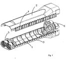
- the splice protection sleeve shown in Figure 1 comprises a lower half-shell 1 and an upper half-shell 2.
- the shell 1 Provided along the longitudinal free edges of the shell 1 are snap-fastening teeth 3 conjugate with snap-fastening openings 4 made along the free longitudinal edges of the half-shell 2.
- These snap-fastening means allow the half-shells to be assembled into a shell after two flanges 5, 6, respectively, have been interposed at the ends.
- each flange consists of two half-flanges 7, 8 which define two semicircular openings 9 and are assembled by a pair of removable assembling means consisting respectively, on the one hand, of two dovetail bars 10, 11 stemming from the two facing-edge generatrices 12 of the two half-flanges 7 and 8, and of a wedge 13 joining the two bars together and having the shape of a plate, the recess of which is conjugate with the shape of the joined-together bars.
- the half-flanges include a tapping 14.
- a longitudinally split ring 15 is interposed between the tapped portion 14 of the sub-flanges and a frustoconical threaded annulus 16 made in two parts joined together by studs 17.
- the annulus 16 is inserted into the opening 9 via its transverse surface of large inside diameter.
- the inside diameter of the small transverse surface of the annulus 16 is smaller than the outside diameter of the ring 15 when it is not deformed.
- the two half-flanges 7 and 8 are assembled by slipping the wedges 13 over the bars 10, 11 and then the split ring 15 and the annulus 16 are slipped on, by screwing the annulus 16 into the tapping 14 until the split ring 15 deforms so as to be in close contact with the outer face of the cable C which had been placed beforehand between the half-flanges 7, 8.
- the cable C is thus well clamped.
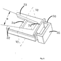
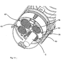
- the flange comprises three sub-flanges 19, 20, 21 which are assembled so as to form four openings 22 for the passage of four cables.
- the assembling means comprise a collar 23 surrounding the outer face of the sub-flanges 19, 20, 21.
- This collar which may be more clearly seen in Figure 4, is split along a longitudinal slit 24.
- a dovetail bar 25, 26 is split along each of the edges of the slit 24, moulded with the inside of the collar.
- the furthest-apart axial edges 27 of the two bars 25, 26 make a wedging angle a between them.
- the faces 28 that have for side, on the one hand, these edges 27 and, on the other hand, the edges 29 common with the collar make between them a taper angle b.
- This wedge which, like all the other parts mentioned hitherto, is made of plastic, has a base 31 from which two branches 32, 33 stem, these branches making between them a wedging angle a.
- the two branches are connected via a transverse piece 34.
- a handle 35 is provided on the other side of the base 31.
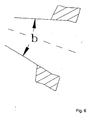
- the inner faces of the branches 32, 33 make between them an angle b in the plane of section VI-VI in Figure 5.
- a ring 36 Engaged respectively in each opening 22 of the flange is a ring 36 which includes a part 37 in the form of multiple bars terminating in inwardly directed teeth 38.
- the ring consists of two portions joined together by male and female parts 39.
- An annulus 16 is then also inserted into each opening so that the bars 37 of the ring 36 deform elastically inwards because the small side of the frustoconical annulus 16 has a smaller diameter than that of the ring when it is not deformed and so that the teeth 38 penetrate the cable C inserted into the opening. The cable is thus well clamped.
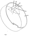
- the splice protection sleeve shown in Figure 8 comprises two half-shells 51 and 52 which may be closed along their longitudinal edges by closure means 53 and 54. Furthermore, the half-shells 51, 52 are closed at their transverse ends by flanges 55, 56.
- the end flange has an outer circumferential groove 57 in which an elastomer seal 58 is placed.
- the half-shell has two inwardly projecting ribs 59, 60 intended to penetrate the seal 58 when the protective sleeve is fully mounted.
- the half-shell On the inner face, the half-shell has respectively two cams 61 which extend in the circumferential direction and which are followed in this direction by housings 62.
- the flange has a stub 63 intended to push the cam 61 back before entering the housing 62.
- the half-shell is moved towards the flange. Initially, the cams 61 and the stubs 63 come respectively into contact so that the half-shell 52 deforms and opens up. It is only when the stubs 63 reach the housings 62 and enter therein that the half-shell 52 resumes its initial position and that the ribs 59, 60 come into contact with the seal 58 and penetrate it. During mounting, the seal 58 is thus hardly stressed in a direction other than normal to its surface.
- the cams 61 are placed on each side of the ribs 60 at a longitudinal distance approximately equal or slightly greater than the thickness of a flange.
- Each cam 61 is close to the longitudinal edge of the half-shell 52. The same applies to the other longitudinal edge of the half-shell 52. There are therefore in total eight cams per half-shell, four among them corresponding to four stubs made on the same flange. Two stubs are on one face of the flange and two others on the opposite face. The same applies to the second flange.
Abstract
Description
- The present invention relates to splice protection sleeves used especially in the telecommunications field for the purpose of protecting a cable, especially a power cable or a telephone cable such as a fibre-optic cable. Furtheron, the present invention relates to splice protection sleeves used especially to protect the splices of power or telecommunications cables, such as a fibre-optic cable.
- Already known is a splice protection sleeve which may comprise two half-shells provided with means for assembling them into a shell or a split shell or a bell-shaped shell. The sleeve has at least one end flange, each flange consisting of at least two sub-flanges together defining a semicircular opening. There may for example be two half-flanges or three sub-flanges. The sub-flanges are assembled by removable assembling means, namely by screws for firmly clamping the cable.
- This assembling by screws has many drawbacks on site. Often seizures may occur or a nut may be missing. Before mounting, measures must be taken to ensure that the screws cannot be lost. They must therefore be placed in a bag to be supplied at the same time as the rest of the plastic parts for constructing the sleeve. This complicates the packaging and the delivery of parts intended to allow the sleeve to be constructed on site. The screws may furthermore be easily lost. They are relatively small in size and, at the place where they are mounted, considerable forces are applied to the plastic parts, forces which cause the plastic to undergo premature ageing.
- A remedy to these drawbacks is provided by a splice protection sleeve which can consist only of plastic parts and can be mounted and removed very quickly.
- The splice protection sleeve of the abovementioned type comprises the assembling means including two dovetail bars and a wedge joining the two bars together, the sub-flanges have a tapped portion, and a deformable ring having at least one elastic part is interposed between the tapped portion and an at least partly frustoconical two-part threaded annulus, the annulus, whose inside diameter of the small transverse surface is smaller than the outside diameter of the undeformed ring, being screwed into the tapped portion of the opening, by being inserted thereinto via its transverse surface of large inside diameter.
- Thus, the screws are entirely replaced with a wedging arrangement obtained with the aid of plastic parts.
- The two bars stem from the two facing-edge generatrices of two half-flanges. This particularly simple embodiment is especially suitable when the flange has only one opening or only two openings for the passage of cables. But when there are more openings, and especially four openings, it is preferred that the two assembling bars be provided on the inner face of a split collar surrounding the sub-flanges along the edges of the slit of this collar respectively. Thus, a multiplicity of wedges and bars does not have to be provided.
- The furthest-apart axial edges of the two bars make between them a wedging angle and, according to a preferred embodiment, for ensuring that the wedge is properly held in place on the bars, the faces that have for side the furthest-apart axial edges and the edges common with the collar make between them a taper angle.
- The wedge may have two branches joined together by a transverse part cooperating with a stop made on the flange. In the open position, the abutting of the transverse piece on the stop prevents the wedge from being lost. In the closed position, that is to say when the wedge clamps the collar, this stop prevents the wedge from coming out inopportunely and from unclamping the collar.
- The wedge may also include a handle allowing it to be easily manipulated and also forming a screen so that inopportune access to the stop is more difficult and any disassembly of the base of the wedge from the stop is made improbable.
- There is another drawback of a splice protection sleeve comprising two half-shells as known from the prior art. The two half-shells are closed by two end flanges which define an opening for the passage of a cable or of several cables. At least one end flange has an outer circumferential groove in which a seal is placed, which seal may be in the form of a solid rubber seal or a seal made of an elastomer material often called a gel. The half-shell includes an inwardly projecting portion intended to penetrate the seal, in order to properly compress the seal.
- The most relevant prior art splice protection sleeve is disclosed in US 4 720 605 A.
- The point where sealing is most difficult to ensure is the point where both the half-shells and the flange meet and where the seal is stressed in two different directions, namely in the circumferential direction and in the longitudinal direction.
- According to the invention this drawback is remedied by an arrangement which improves the sealing provided by the seal.
- According to the invention, the half-shell includes, on the inner face, a cam which extends in the circumferential direction and is followed in this direction by a housing and the flange includes a stub placed so as to push the cam back before entering the housing when the half-shell is moved closer to the flange.
- During mounting, while the half-shell is being put into place from the top or from below onto the flange, both parts being made of plastic, the stub firstly pushes the cam, and therefore the half-shell, back so as to force it to deform and open up, in order for the half-shell to come onto the flange, and especially onto the elastomer or gel seal, approximately perpendicular to the latter and no longer in a direction substantially tangential thereto. It is only when the stub penetrates the housing that the half-shell suddenly resumes its position without beforehand having made the seal undergo a rolling motion. Now, it is this rolling motion in the circumferential direction which hitherto created a build-up of material at the triple point, giving rise to leakage lines, making closure more difficult and necessarily causing at other places a reduction in the amount of material of the seal, which compromised the sealing. The co-operation of the stub with the housing furthermore ensures that there is a link between the half-shell and the flange.
- In the appended drawing, given solely by way of example:
- Figure 1 is a perspective view of a sleeve;
- Figure 2 is an exploded perspective view illustrating an end flange;
- Figure 3 is a perspective view of a mounted end flange;
- Figure 4 is a perspective view illustrating the collar;
- Figure 5 is a perspective view illustrating the wedge;
- Figure 6 is a sectional view on the line VI-VI in Figure 5;
- Figure 7 is a perspective view of the ring;
- Figure 8 is a perspective view of a protective sleeve when the half-shells are a certain distance apart;
- Figure 9 is a partial perspective view of the flange;
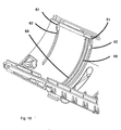
- Figure 10 is a partial perspective view of the inside of the half-shell used according to the invention; and
- Figure 11 is a perspective view of the sleeve of Figure 8 when the cams are co-operating with the stubs.
- The splice protection sleeve shown in Figure 1 comprises a lower half-shell 1 and an upper half-
shell 2. Provided along the longitudinal free edges of the shell 1 are snap-fasteningteeth 3 conjugate with snap-fastening openings 4 made along the free longitudinal edges of the half-shell 2. These snap-fastening means allow the half-shells to be assembled into a shell after twoflanges - As shown in Figure 2, each flange consists of two half-
flanges dovetail bars edge generatrices 12 of the two half-flanges wedge 13 joining the two bars together and having the shape of a plate, the recess of which is conjugate with the shape of the joined-together bars. The half-flanges include a tapping 14. A longitudinallysplit ring 15 is interposed between the tappedportion 14 of the sub-flanges and a frustoconical threadedannulus 16 made in two parts joined together bystuds 17. Theannulus 16 is inserted into the opening 9 via its transverse surface of large inside diameter. The inside diameter of the small transverse surface of theannulus 16 is smaller than the outside diameter of thering 15 when it is not deformed. - During mounting, the two half-
flanges wedges 13 over thebars split ring 15 and theannulus 16 are slipped on, by screwing theannulus 16 into the tapping 14 until thesplit ring 15 deforms so as to be in close contact with the outer face of the cable C which had been placed beforehand between the half-flanges - In Figure 3, the flange comprises three
sub-flanges openings 22 for the passage of four cables. The assembling means comprise acollar 23 surrounding the outer face of thesub-flanges longitudinal slit 24. Along each of the edges of theslit 24, moulded with the inside of the collar, is adovetail bar axial edges 27 of the twobars edges 27 and, on the other hand, theedges 29 common with the collar make between them a taper angle b. - The sub-flanges 19, 20 and 21 are held together by the fact that the
collar 23 is held clamped against it by the cooperation of the dovetail bars 25, 26 and of a wedge which may be more clearly seen in Figure 5 and Figure 6. - This wedge, which, like all the other parts mentioned hitherto, is made of plastic, has a base 31 from which two
branches transverse piece 34. Ahandle 35 is provided on the other side of thebase 31. As shown in Figure 6, the inner faces of thebranches - Engaged respectively in each opening 22 of the flange is a
ring 36 which includes apart 37 in the form of multiple bars terminating in inwardly directedteeth 38. The ring consists of two portions joined together by male andfemale parts 39. Anannulus 16 is then also inserted into each opening so that thebars 37 of thering 36 deform elastically inwards because the small side of thefrustoconical annulus 16 has a smaller diameter than that of the ring when it is not deformed and so that theteeth 38 penetrate the cable C inserted into the opening. The cable is thus well clamped. - The splice protection sleeve shown in Figure 8 comprises two half-
shells shells flanges - In Figure 9, the end flange has an outer
circumferential groove 57 in which anelastomer seal 58 is placed. - In Figure 10, the half-shell has two inwardly projecting
ribs seal 58 when the protective sleeve is fully mounted. On the inner face, the half-shell has respectively twocams 61 which extend in the circumferential direction and which are followed in this direction byhousings 62. - In Figure 11, the flange has a
stub 63 intended to push thecam 61 back before entering thehousing 62. - During mounting, the half-shell is moved towards the flange. Initially, the
cams 61 and thestubs 63 come respectively into contact so that the half-shell 52 deforms and opens up. It is only when thestubs 63 reach thehousings 62 and enter therein that the half-shell 52 resumes its initial position and that theribs seal 58 and penetrate it. During mounting, theseal 58 is thus hardly stressed in a direction other than normal to its surface. - The
cams 61 are placed on each side of theribs 60 at a longitudinal distance approximately equal or slightly greater than the thickness of a flange. - Each
cam 61 is close to the longitudinal edge of the half-shell 52. The same applies to the other longitudinal edge of the half-shell 52. There are therefore in total eight cams per half-shell, four among them corresponding to four stubs made on the same flange. Two stubs are on one face of the flange and two others on the opposite face. The same applies to the second flange.
Claims (5)
- Splice protection sleeve comprising two half-shells (51, 52) closed by two end flanges (55, 56), at least one end flange having an outer circumferential groove (57) in which a seal (58) is placed and one half-shell (51, 52) having an inwardly projecting portion (59, 60) intended to penetrate the seal (8), characterized in that the half-shell (51, 52) includes, on the inner face, a cam (61) which extends in the circumferential direction and is followed in this direction by a housing (62) and the flange (55, 56) includes a stub (63) placed so as to push the cam (61) back before entering the housing (62) when the half-shell (51) is moved closer to the flange (55, 56).
- Sleeve according to Claim 1, characterized in that the cam is close to the longitudinal edge of the half-shell.
- Sleeve according to Claim 2, characterized by a cam close to each longitudinal edge of the half-shell.
- Sleeve according to Claim 3, characterized by two cams close to each longitudinal edge of the half-shell.
- Sleeve according to Claim 4, characterized by four stubs for each flange.
Applications Claiming Priority (5)
| Application Number | Priority Date | Filing Date | Title |
|---|---|---|---|
| FR0108597 | 2001-06-29 | ||
| FR0108602A FR2826796B1 (en) | 2001-06-29 | 2001-06-29 | SPLICE PROTECTIVE SLEEVE WITH SEAL PROTECTION PROTECTION |
| FR0108602 | 2001-06-29 | ||
| FR0108597A FR2826794B1 (en) | 2001-06-29 | 2001-06-29 | SPLICE PROTECTION SLEEVE WITH FLANGE ASSEMBLED BY CORNER |
| EP02754722A EP1399996B1 (en) | 2001-06-29 | 2002-06-20 | Splice protection sleeve |
Related Parent Applications (1)
| Application Number | Title | Priority Date | Filing Date |
|---|---|---|---|
| EP02754722A Division EP1399996B1 (en) | 2001-06-29 | 2002-06-20 | Splice protection sleeve |
Publications (2)
| Publication Number | Publication Date |
|---|---|
| EP1536536A1 EP1536536A1 (en) | 2005-06-01 |
| EP1536536B1 true EP1536536B1 (en) | 2006-03-22 |
Family
ID=26213072
Family Applications (2)
| Application Number | Title | Priority Date | Filing Date |
|---|---|---|---|
| EP05004242A Expired - Lifetime EP1536536B1 (en) | 2001-06-29 | 2002-06-20 | Splice protection sleeve |
| EP02754722A Expired - Lifetime EP1399996B1 (en) | 2001-06-29 | 2002-06-20 | Splice protection sleeve |
Family Applications After (1)
| Application Number | Title | Priority Date | Filing Date |
|---|---|---|---|
| EP02754722A Expired - Lifetime EP1399996B1 (en) | 2001-06-29 | 2002-06-20 | Splice protection sleeve |
Country Status (9)
| Country | Link |
|---|---|
| US (1) | US6944388B2 (en) |
| EP (2) | EP1536536B1 (en) |
| AT (2) | ATE304235T1 (en) |
| BR (1) | BR0209582A (en) |
| CA (1) | CA2444728A1 (en) |
| DE (2) | DE60206044T2 (en) |
| ES (2) | ES2262126T3 (en) |
| MX (1) | MXPA03011938A (en) |
| WO (1) | WO2003003533A2 (en) |
Cited By (1)
| Publication number | Priority date | Publication date | Assignee | Title |
|---|---|---|---|---|
| EP2182601A1 (en) | 2008-10-30 | 2010-05-05 | 3M Innovative Properties Company | Sealing enclosure |
Families Citing this family (10)
| Publication number | Priority date | Publication date | Assignee | Title |
|---|---|---|---|---|
| US7011454B2 (en) * | 2003-08-25 | 2006-03-14 | Panduit Corp. | Reversible fiber optic stub fiber connector |
| US6948976B2 (en) * | 2004-03-01 | 2005-09-27 | Andrew Corporation | Cable and apparatus interface environmental seal |
| US7177518B2 (en) * | 2004-05-11 | 2007-02-13 | Fomguard Inc. | Clips for holding fiber optic cables of a security fence |
| US20080037946A1 (en) * | 2006-08-14 | 2008-02-14 | John George | Multicable clamp |
| SE0850021L (en) * | 2008-09-23 | 2009-12-29 | Syntune Ab | Waveguide for low reflex switch-off. |
| WO2013170291A1 (en) * | 2012-05-14 | 2013-11-21 | Next Wave Design Pty Ltd | Cable holder |
| BR112013024020B1 (en) * | 2012-06-15 | 2022-06-28 | João Martins Neto | CABLE GOLD WITH TIGHTENING INDICATOR |
| WO2016109425A1 (en) * | 2014-12-29 | 2016-07-07 | Commscope Technologies Llc | Telecommunications enclosure with cable seal |
| CN112403848A (en) * | 2020-10-27 | 2021-02-26 | 李钢 | Heat-insulation protective sleeve for gluing and drying wire harness connector |
| FR3120139B1 (en) * | 2021-02-23 | 2023-11-24 | Omelcom | Connection box with a sealing device provided with a longitudinal part |
Family Cites Families (6)
| Publication number | Priority date | Publication date | Assignee | Title |
|---|---|---|---|---|
| JPH0353561Y2 (en) * | 1985-09-27 | 1991-11-22 | ||
| NL9201676A (en) * | 1992-09-29 | 1994-04-18 | Odink & Koenderink Bv | Electrical mounting box, especially a junction box |
| DE4333067C1 (en) * | 1993-09-29 | 1995-03-09 | Rose Walter Gmbh & Co Kg | Device for forming a socket inlet, in particular for fiber optic cables |
| WO1997012268A1 (en) * | 1995-09-29 | 1997-04-03 | Psi Telecommunications, Inc. | Fiber optic cable splice closure |
| US5598499A (en) * | 1995-11-01 | 1997-01-28 | Lucent Technologies, Inc. | Seal for cable splice closure |
| MXPA03010718A (en) * | 2001-05-25 | 2005-03-07 | Preformed Line Products Co | Fiber optic cable closure. |
-
2002
- 2002-06-20 DE DE60206044T patent/DE60206044T2/en not_active Expired - Fee Related
- 2002-06-20 AT AT02754722T patent/ATE304235T1/en not_active IP Right Cessation
- 2002-06-20 AT AT05004242T patent/ATE321369T1/en not_active IP Right Cessation
- 2002-06-20 BR BR0209582-3A patent/BR0209582A/en not_active IP Right Cessation
- 2002-06-20 US US10/482,075 patent/US6944388B2/en not_active Expired - Lifetime
- 2002-06-20 EP EP05004242A patent/EP1536536B1/en not_active Expired - Lifetime
- 2002-06-20 MX MXPA03011938A patent/MXPA03011938A/en active IP Right Grant
- 2002-06-20 EP EP02754722A patent/EP1399996B1/en not_active Expired - Lifetime
- 2002-06-20 ES ES05004242T patent/ES2262126T3/en not_active Expired - Lifetime
- 2002-06-20 WO PCT/EP2002/006832 patent/WO2003003533A2/en not_active Application Discontinuation
- 2002-06-20 DE DE60210151T patent/DE60210151T2/en not_active Expired - Fee Related
- 2002-06-20 CA CA002444728A patent/CA2444728A1/en not_active Abandoned
- 2002-06-20 ES ES02754722T patent/ES2248589T3/en not_active Expired - Lifetime
Cited By (1)
| Publication number | Priority date | Publication date | Assignee | Title |
|---|---|---|---|---|
| EP2182601A1 (en) | 2008-10-30 | 2010-05-05 | 3M Innovative Properties Company | Sealing enclosure |
Also Published As
| Publication number | Publication date |
|---|---|
| EP1536536A1 (en) | 2005-06-01 |
| WO2003003533A2 (en) | 2003-01-09 |
| ES2262126T3 (en) | 2006-11-16 |
| MXPA03011938A (en) | 2005-03-07 |
| CA2444728A1 (en) | 2003-01-09 |
| US20040208467A1 (en) | 2004-10-21 |
| WO2003003533A3 (en) | 2003-05-01 |
| ATE321369T1 (en) | 2006-04-15 |
| ATE304235T1 (en) | 2005-09-15 |
| DE60206044T2 (en) | 2006-07-13 |
| BR0209582A (en) | 2004-06-22 |
| ES2248589T3 (en) | 2006-03-16 |
| EP1399996A2 (en) | 2004-03-24 |
| DE60210151T2 (en) | 2007-03-08 |
| EP1399996B1 (en) | 2005-09-07 |
| DE60206044D1 (en) | 2005-10-13 |
| DE60210151D1 (en) | 2006-05-11 |
| US6944388B2 (en) | 2005-09-13 |
Similar Documents
| Publication | Publication Date | Title |
|---|---|---|
| EP1536536B1 (en) | Splice protection sleeve | |
| EP0731998B1 (en) | An end plate for forming a seal around an elongate object | |
| EP0782776B1 (en) | Cable splice closure | |
| US5517592A (en) | Sleeve for branch or joint areas in optical or electrical cables | |
| US4117259A (en) | Cable sleeve | |
| KR100337568B1 (en) | Cable Sealing Device | |
| KR20010107949A (en) | Cable closure | |
| US10211616B2 (en) | Cable/line insertion | |
| GB2546750A (en) | A cable splice closure | |
| US4692565A (en) | Segmented end seal and closure | |
| EP0728377B1 (en) | Cable closure | |
| EP0587621A1 (en) | Cable sealing | |
| US5561272A (en) | Sleeve head having a plurality of cable introduction openings | |
| EP3576238B1 (en) | A cable gland | |
| WO1996009673A1 (en) | Sealing device |
Legal Events
| Date | Code | Title | Description |
|---|---|---|---|
| PUAI | Public reference made under article 153(3) epc to a published international application that has entered the european phase |
Free format text: ORIGINAL CODE: 0009012 |
|
| 17P | Request for examination filed |
Effective date: 20050305 |
|
| AC | Divisional application: reference to earlier application |
Ref document number: 1399996 Country of ref document: EP Kind code of ref document: P |
|
| AK | Designated contracting states |
Kind code of ref document: A1 Designated state(s): AT BE CH CY DE DK ES FI FR GB GR IE IT LI LU MC NL PT SE TR |
|
| RAP1 | Party data changed (applicant data changed or rights of an application transferred) |
Owner name: CCS TECHNOLOGY, INC. |
|
| GRAP | Despatch of communication of intention to grant a patent |
Free format text: ORIGINAL CODE: EPIDOSNIGR1 |
|
| GRAS | Grant fee paid |
Free format text: ORIGINAL CODE: EPIDOSNIGR3 |
|
| GRAA | (expected) grant |
Free format text: ORIGINAL CODE: 0009210 |
|
| AKX | Designation fees paid |
Designated state(s): AT BE CH CY DE DK ES FI FR GB GR IE IT LI LU MC NL PT SE TR |
|
| AC | Divisional application: reference to earlier application |
Ref document number: 1399996 Country of ref document: EP Kind code of ref document: P |
|
| AK | Designated contracting states |
Kind code of ref document: B1 Designated state(s): AT BE CH CY DE DK ES FI FR GB GR IE IT LI LU MC NL PT SE TR |
|
| PG25 | Lapsed in a contracting state [announced via postgrant information from national office to epo] |
Ref country code: IT Free format text: LAPSE BECAUSE OF FAILURE TO SUBMIT A TRANSLATION OF THE DESCRIPTION OR TO PAY THE FEE WITHIN THE PRESCRIBED TIME-LIMIT;WARNING: LAPSES OF ITALIAN PATENTS WITH EFFECTIVE DATE BEFORE 2007 MAY HAVE OCCURRED AT ANY TIME BEFORE 2007. THE CORRECT EFFECTIVE DATE MAY BE DIFFERENT FROM THE ONE RECORDED. Effective date: 20060322 Ref country code: AT Free format text: LAPSE BECAUSE OF FAILURE TO SUBMIT A TRANSLATION OF THE DESCRIPTION OR TO PAY THE FEE WITHIN THE PRESCRIBED TIME-LIMIT Effective date: 20060322 Ref country code: CH Free format text: LAPSE BECAUSE OF FAILURE TO SUBMIT A TRANSLATION OF THE DESCRIPTION OR TO PAY THE FEE WITHIN THE PRESCRIBED TIME-LIMIT Effective date: 20060322 Ref country code: NL Free format text: LAPSE BECAUSE OF FAILURE TO SUBMIT A TRANSLATION OF THE DESCRIPTION OR TO PAY THE FEE WITHIN THE PRESCRIBED TIME-LIMIT Effective date: 20060322 Ref country code: LI Free format text: LAPSE BECAUSE OF FAILURE TO SUBMIT A TRANSLATION OF THE DESCRIPTION OR TO PAY THE FEE WITHIN THE PRESCRIBED TIME-LIMIT Effective date: 20060322 |
|
| REG | Reference to a national code |
Ref country code: GB Ref legal event code: FG4D |
|
| REG | Reference to a national code |
Ref country code: CH Ref legal event code: EP |
|
| REG | Reference to a national code |
Ref country code: IE Ref legal event code: FG4D |
|
| REF | Corresponds to: |
Ref document number: 60210151 Country of ref document: DE Date of ref document: 20060511 Kind code of ref document: P |
|
| PG25 | Lapsed in a contracting state [announced via postgrant information from national office to epo] |
Ref country code: IE Free format text: LAPSE BECAUSE OF NON-PAYMENT OF DUE FEES Effective date: 20060620 |
|
| PG25 | Lapsed in a contracting state [announced via postgrant information from national office to epo] |
Ref country code: DK Free format text: LAPSE BECAUSE OF FAILURE TO SUBMIT A TRANSLATION OF THE DESCRIPTION OR TO PAY THE FEE WITHIN THE PRESCRIBED TIME-LIMIT Effective date: 20060622 Ref country code: SE Free format text: LAPSE BECAUSE OF FAILURE TO SUBMIT A TRANSLATION OF THE DESCRIPTION OR TO PAY THE FEE WITHIN THE PRESCRIBED TIME-LIMIT Effective date: 20060622 |
|
| PG25 | Lapsed in a contracting state [announced via postgrant information from national office to epo] |
Ref country code: MC Free format text: LAPSE BECAUSE OF NON-PAYMENT OF DUE FEES Effective date: 20060630 |
|
| PG25 | Lapsed in a contracting state [announced via postgrant information from national office to epo] |
Ref country code: PT Free format text: LAPSE BECAUSE OF FAILURE TO SUBMIT A TRANSLATION OF THE DESCRIPTION OR TO PAY THE FEE WITHIN THE PRESCRIBED TIME-LIMIT Effective date: 20060822 |
|
| NLV1 | Nl: lapsed or annulled due to failure to fulfill the requirements of art. 29p and 29m of the patents act | ||
| REG | Reference to a national code |
Ref country code: CH Ref legal event code: PL |
|
| ET | Fr: translation filed | ||
| REG | Reference to a national code |
Ref country code: ES Ref legal event code: FG2A Ref document number: 2262126 Country of ref document: ES Kind code of ref document: T3 |
|
| PLBE | No opposition filed within time limit |
Free format text: ORIGINAL CODE: 0009261 |
|
| STAA | Information on the status of an ep patent application or granted ep patent |
Free format text: STATUS: NO OPPOSITION FILED WITHIN TIME LIMIT |
|
| 26N | No opposition filed |
Effective date: 20061227 |
|
| PGFP | Annual fee paid to national office [announced via postgrant information from national office to epo] |
Ref country code: ES Payment date: 20070626 Year of fee payment: 6 |
|
| PGFP | Annual fee paid to national office [announced via postgrant information from national office to epo] |
Ref country code: DE Payment date: 20070731 Year of fee payment: 6 |
|
| PGFP | Annual fee paid to national office [announced via postgrant information from national office to epo] |
Ref country code: BE Payment date: 20070716 Year of fee payment: 6 |
|
| PG25 | Lapsed in a contracting state [announced via postgrant information from national office to epo] |
Ref country code: GR Free format text: LAPSE BECAUSE OF FAILURE TO SUBMIT A TRANSLATION OF THE DESCRIPTION OR TO PAY THE FEE WITHIN THE PRESCRIBED TIME-LIMIT Effective date: 20060623 |
|
| PGFP | Annual fee paid to national office [announced via postgrant information from national office to epo] |
Ref country code: FR Payment date: 20070618 Year of fee payment: 6 |
|
| PG25 | Lapsed in a contracting state [announced via postgrant information from national office to epo] |
Ref country code: FI Free format text: LAPSE BECAUSE OF FAILURE TO SUBMIT A TRANSLATION OF THE DESCRIPTION OR TO PAY THE FEE WITHIN THE PRESCRIBED TIME-LIMIT Effective date: 20060322 |
|
| PG25 | Lapsed in a contracting state [announced via postgrant information from national office to epo] |
Ref country code: LU Free format text: LAPSE BECAUSE OF NON-PAYMENT OF DUE FEES Effective date: 20060620 Ref country code: TR Free format text: LAPSE BECAUSE OF FAILURE TO SUBMIT A TRANSLATION OF THE DESCRIPTION OR TO PAY THE FEE WITHIN THE PRESCRIBED TIME-LIMIT Effective date: 20060322 |
|
| PG25 | Lapsed in a contracting state [announced via postgrant information from national office to epo] |
Ref country code: CY Free format text: LAPSE BECAUSE OF FAILURE TO SUBMIT A TRANSLATION OF THE DESCRIPTION OR TO PAY THE FEE WITHIN THE PRESCRIBED TIME-LIMIT Effective date: 20060322 |
|
| BERE | Be: lapsed |
Owner name: *CCS TECHNOLOGY INC. Effective date: 20080630 |
|
| PGFP | Annual fee paid to national office [announced via postgrant information from national office to epo] |
Ref country code: GB Payment date: 20080627 Year of fee payment: 7 |
|
| PG25 | Lapsed in a contracting state [announced via postgrant information from national office to epo] |
Ref country code: BE Free format text: LAPSE BECAUSE OF NON-PAYMENT OF DUE FEES Effective date: 20080630 |
|
| REG | Reference to a national code |
Ref country code: FR Ref legal event code: ST Effective date: 20090228 |
|
| PG25 | Lapsed in a contracting state [announced via postgrant information from national office to epo] |
Ref country code: DE Free format text: LAPSE BECAUSE OF NON-PAYMENT OF DUE FEES Effective date: 20090101 |
|
| REG | Reference to a national code |
Ref country code: ES Ref legal event code: FD2A Effective date: 20080621 |
|
| PG25 | Lapsed in a contracting state [announced via postgrant information from national office to epo] |
Ref country code: FR Free format text: LAPSE BECAUSE OF NON-PAYMENT OF DUE FEES Effective date: 20080630 |
|
| PG25 | Lapsed in a contracting state [announced via postgrant information from national office to epo] |
Ref country code: ES Free format text: LAPSE BECAUSE OF NON-PAYMENT OF DUE FEES Effective date: 20080621 |
|
| GBPC | Gb: european patent ceased through non-payment of renewal fee |
Effective date: 20090620 |
|
| PG25 | Lapsed in a contracting state [announced via postgrant information from national office to epo] |
Ref country code: GB Free format text: LAPSE BECAUSE OF NON-PAYMENT OF DUE FEES Effective date: 20090620 |