EP1536301A2 - Dispositif à deux canaux avec une étape d'introduction de signaux numériques et une étape de contrôle de sortie numérique - Google Patents
Dispositif à deux canaux avec une étape d'introduction de signaux numériques et une étape de contrôle de sortie numérique Download PDFInfo
- Publication number
- EP1536301A2 EP1536301A2 EP20040090407 EP04090407A EP1536301A2 EP 1536301 A2 EP1536301 A2 EP 1536301A2 EP 20040090407 EP20040090407 EP 20040090407 EP 04090407 A EP04090407 A EP 04090407A EP 1536301 A2 EP1536301 A2 EP 1536301A2
- Authority
- EP
- European Patent Office
- Prior art keywords
- channel unit
- levels
- controllers
- inputs
- computer
- Prior art date
- Legal status (The legal status is an assumption and is not a legal conclusion. Google has not performed a legal analysis and makes no representation as to the accuracy of the status listed.)
- Withdrawn
Links
- 230000011664 signaling Effects 0.000 title description 3
- 238000012360 testing method Methods 0.000 claims abstract description 18
- 238000002955 isolation Methods 0.000 claims abstract description 5
- 238000000926 separation method Methods 0.000 claims description 10
- 230000002093 peripheral effect Effects 0.000 claims description 6
- 230000003287 optical effect Effects 0.000 abstract 1
- 230000035515 penetration Effects 0.000 description 4
- 238000004891 communication Methods 0.000 description 1
- 238000010276 construction Methods 0.000 description 1
- 230000001419 dependent effect Effects 0.000 description 1
- 230000009977 dual effect Effects 0.000 description 1
- 238000009434 installation Methods 0.000 description 1
- 238000000034 method Methods 0.000 description 1
- 238000004088 simulation Methods 0.000 description 1
Images
Classifications
-
- H—ELECTRICITY
- H04—ELECTRIC COMMUNICATION TECHNIQUE
- H04L—TRANSMISSION OF DIGITAL INFORMATION, e.g. TELEGRAPHIC COMMUNICATION
- H04L12/00—Data switching networks
- H04L12/28—Data switching networks characterised by path configuration, e.g. LAN [Local Area Networks] or WAN [Wide Area Networks]
- H04L12/40—Bus networks
- H04L12/40169—Flexible bus arrangements
- H04L12/40176—Flexible bus arrangements involving redundancy
-
- G—PHYSICS
- G05—CONTROLLING; REGULATING
- G05B—CONTROL OR REGULATING SYSTEMS IN GENERAL; FUNCTIONAL ELEMENTS OF SUCH SYSTEMS; MONITORING OR TESTING ARRANGEMENTS FOR SUCH SYSTEMS OR ELEMENTS
- G05B9/00—Safety arrangements
- G05B9/02—Safety arrangements electric
- G05B9/03—Safety arrangements electric with multiple-channel loop, i.e. redundant control systems
-
- H—ELECTRICITY
- H04—ELECTRIC COMMUNICATION TECHNIQUE
- H04L—TRANSMISSION OF DIGITAL INFORMATION, e.g. TELEGRAPHIC COMMUNICATION
- H04L12/00—Data switching networks
- H04L12/28—Data switching networks characterised by path configuration, e.g. LAN [Local Area Networks] or WAN [Wide Area Networks]
- H04L12/40—Bus networks
- H04L12/40006—Architecture of a communication node
- H04L12/40013—Details regarding a bus controller
Definitions
- the invention relates to a two-channel unit with input side digital reporting levels or output digital Command levels according to the preambles of the claims 1 and 7.
- Safe working safety equipment are known. These may be signal lamps, turnout drives, Axle counters, emergency signaling devices and the like act in the grounds of a signal box.
- the indoor unit of such a signal box today includes a parent secure machine that comes with a host of others Components of the indoor system is connected. In these Components can be two-channel units either act with digital notification or command levels. These must for safety reasons regarding their functionality be checked cyclically.
- the unit has one for each Channel via a controller, each from the safe Computer is controllable.
- the message or command levels are for safety reasons two channels, whereby the two Controller each with an input and an output the two message or command levels of a pair connected are.
- an electronic test circuit be provided, so controlled by the controllers is that all inputs of the reporting levels are grounded can be. After that are prescribed by the controller Bit pattern for the simulation of digital input signals given the inputs of the reporting levels, which then entspredie with Inputs of the reporting levels given, which then with appropriate Output signals respond to which the parent Computer in turn has access via the controller.
- each a temporally short impulse on the inputs of the command levels be given sequentially, i. chronologically one pulse at a time on one input.
- the Impulses are sized so that it is at the entrances to a momentary state inversion comes.
- the short term changed output signals are in turn detected and provided to the associated secure computer.
- a disadvantage of the known unit is that these due the many optocouplers relatively large-scale and expensive is.
- a Safety-related control circuit with two transceivers A and B known which the two channels of the circuit form.
- a parent master controls two stations or controllers CPU A and CPU B; these are each with an input and an output of the reporting levels connected, which are formed two channels.
- the inputs of the reporting levels can be from the controllers CPU A, CPU B set to a defined state and simulated Input signals are given to the inputs. This way caused output signals are by user software captured and made available to the parent master.
- the controller CPU A, CPU B communicate with the master via separate and independent serial buses. there Each serial bus has a potential separation, the is effected by means of optocouplers.
- the message and command levels of the input / output level are the same built that they both as inputs and outputs as well as for Connection of other serial bus systems can be used. On this way it allows the interconnection of the input / output pairs, to check these with the help of test patterns as well as switching the connections to defined states.
- the Message and command levels can therefore be controlled by a dual, redundant bus system with a higher-level safe Master be connected so that all reference potentials are separated from each other.
- dielectric strength are two parting planes present, one in the bus at the master and the other in the bus Output levels (output levels).
- the object of the invention is the potential separation using optocouplers to ensure even in case of error.
- test is simplified when the inputs the current-sensitive reporting levels are grounded.
- a simple security circuit provides that one of the Computer controlled switching unit is provided which in the Error, the supply voltage of the connected peripherals off.
- test quality is increased when the inputs given to the inputs simulated digital input signals predetermined bit pattern are, and those, which are in the examination of Have proven to be effective.
- the solution also includes the two-channel unit digital command levels before that one Power loss limitation of the optocoupler is provided.
- the state inversion becomes pulsed, the logical state of the Command levels are changed so impulsively.
- test is simplified if for Power loss limiting the optocouplers below the Nominal operating voltage can be operated and the Operating voltage via series resistors on the optocouplers is applied.
- a safety shutdown is guaranteed if one of the Computer controlled switching unit is provided which in the Error, the supply voltage of the connected peripherals off.
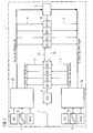
- Fig. 1 shows a two-channel unit 1 with digital Reporting levels MS, which for reasons of security reasons Message level pairs are executed and to a not shown Process connection for the safe operation of a safety-related Furnishings of the indoor facility belong, therefore For example, for the control of signal lamps, turnout drives, Axle counters, free-field devices, speed measuring devices and driving locks as well for safe Contact queries.
- each notification level MSO-MS7 is connected to two controllers 2a, 2b, each Controller 2a, 2b each with an input and an output the reporting level pairs.
- the Controller 2a with the input of a message level MS and the Output of the other reporting level MS connected.
- a test circuit 5 which is based on a command from the controller 2b (testing the reporting levels) all inputs of the reporting levels MSO-MS7 to ground (by the arrows 5a, 5b is the Passing through the test circuit 5 shown), which is a simple Possibility is to change the reporting levels MSO-MS7 to the state Zero.
- the state zero is one of two defined ones Input states of reporting levels MSO-MS7.
- Subsequently are simulated by the two controllers 2a, 2b Input signals to the inputs of all eight reporting levels MSO-MS7 given (testing the reporting levels), as predetermined bit patterns, preferably such bit patterns Be used already for such tests have proven to be successful.
- the output signals of the bit patterns are from the controllers 2a, 2b detected (reading the messages) and are available to the higher-level secure computer (not shown) via the controller 2 available.
- the controllers 2a, 2b communicate with the computer via a serial bus 6, which - as in Fig. 1 by the two diagonal bars - a potential separation 6a has, here by means of two optocouplers (not shown).
- a power loss limitation of the optocoupler provided by the optocouplers below the Nominal operating voltage can be operated and the Operating voltage via series resistors on the optocouplers is applied.
- connection 7 is the parent computer with connected to a switching unit ASS, which from the secure computer directly controlled the supply voltage of the connected Disables the peripheral to its shutdown command (Through the arrows 7a, 7b, the penetration is shown schematically).
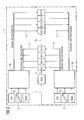
- Fig. 2 shows a two-channel unit with output side digital command levels KS instead of the reporting levels MS. As a comparison of Fig. 1 and Fig. 2 shows immediately, is shown in FIG. 2 no test circuit 5 is present, i. the command levels KS do not need to advance to a defined state for testing be set.
- the controllers 2a, 2b each have a state inversion sequentially to the inputs of the command levels KS, namely from the controller 2b to the command levels KS0 - KS3 and from the controller 2a to the command levels KS4 - KS7, which is referred to in Fig. 2 as controlling the commands is.
- the state inversion takes the form of short pulses, for example voltage pulses, during any current state at each input of the command levels.
- the resulting output signals (pulse signals) are recorded (read back the commands) and the safe Calculator provided.
- a serial bus 6 is for communication with the provided safe computer, in turn, a potential separation 6a by means of optocouplers. Also is one Power loss limitation of the optocouplers provided by operated the optocouplers below the nominal operating voltage and the operating voltage via series resistors to the Optocouplers is present.
- the secure computer can supply the supply voltage the connected peripherals are all connected to the Command levels connectable consumers, such as relays etc., via the switching unit ASS turn off what is through the arrows 7a and 7b is shown, with the arrows 7a and 7b show the penetration of the switching unit ASS.
Landscapes
- Engineering & Computer Science (AREA)
- Physics & Mathematics (AREA)
- General Physics & Mathematics (AREA)
- Automation & Control Theory (AREA)
- Computer Networks & Wireless Communication (AREA)
- Signal Processing (AREA)
- Emergency Protection Circuit Devices (AREA)
- Safety Devices In Control Systems (AREA)
Applications Claiming Priority (2)
| Application Number | Priority Date | Filing Date | Title |
|---|---|---|---|
| DE10355863 | 2003-11-25 | ||
| DE10355863 | 2003-11-25 |
Publications (1)
| Publication Number | Publication Date |
|---|---|
| EP1536301A2 true EP1536301A2 (fr) | 2005-06-01 |
Family
ID=34442354
Family Applications (1)
| Application Number | Title | Priority Date | Filing Date |
|---|---|---|---|
| EP20040090407 Withdrawn EP1536301A2 (fr) | 2003-11-25 | 2004-10-22 | Dispositif à deux canaux avec une étape d'introduction de signaux numériques et une étape de contrôle de sortie numérique |
Country Status (2)
| Country | Link |
|---|---|
| EP (1) | EP1536301A2 (fr) |
| CA (1) | CA2488160A1 (fr) |
Cited By (1)
| Publication number | Priority date | Publication date | Assignee | Title |
|---|---|---|---|---|
| CN101137181B (zh) * | 2007-10-09 | 2010-06-09 | 中兴通讯股份有限公司 | 一种负荷测试方法及装置 |
-
2004
- 2004-10-22 EP EP20040090407 patent/EP1536301A2/fr not_active Withdrawn
- 2004-11-23 CA CA 2488160 patent/CA2488160A1/fr not_active Abandoned
Cited By (1)
| Publication number | Priority date | Publication date | Assignee | Title |
|---|---|---|---|---|
| CN101137181B (zh) * | 2007-10-09 | 2010-06-09 | 中兴通讯股份有限公司 | 一种负荷测试方法及装置 |
Also Published As
| Publication number | Publication date |
|---|---|
| CA2488160A1 (fr) | 2005-05-25 |
Similar Documents
| Publication | Publication Date | Title |
|---|---|---|
| DE3236812C2 (de) | Fernwirksystem | |
| DE60110435T2 (de) | Elektronisches sicherheitssystem für fahrtreppe | |
| EP0875810B1 (fr) | Méthode et dispositif de surveillance d'une installation comprenant plusieurs unités fonctionnelles | |
| DE19643092C2 (de) | Feld-Datenbussystem | |
| EP3069202B1 (fr) | Commande de sécurité à entrées configurables | |
| DE10353950C5 (de) | Steuerungssystem | |
| EP0082859B1 (fr) | Systeme regulateur antiblocage | |
| EP0742500A2 (fr) | Fonctions de commutateur simple et à contact à sûreté intégrée avec évitement d'erreur | |
| EP0007579B1 (fr) | Circuit de surveillance de l'état de systèmes de signalisation, spécialement de systèmes lumineux de signalisation de circulation routière | |
| EP3100121B1 (fr) | Procédé et dispositif pour déconnecter en toute sécurité une charge électrique | |
| DE102013106739A1 (de) | Sicherheitsschaltvorrichtung mit fehlersicheren Eingängen | |
| EP0004909B1 (fr) | Avertisseur de danger | |
| DE102016000126A1 (de) | Serielles Bussystem mit Koppelmodulen | |
| DE102013102998A1 (de) | Sicherheitssignal-Bearbeitungssystem | |
| EP3745217A1 (fr) | Procédé et dispositif de surveillance d'un système de traitement et de transmission de données. | |
| DE102007048122A1 (de) | Vorrichtung und Verfahren zur Aktorüberwachung eines zweikanalig angeschalteten sicherheitstechnischen Lastkreises | |
| DE2029874B2 (de) | Überwachungsschaltung | |
| DE102005055428A1 (de) | Busmodul zum Anschluss an ein Bussystem sowie Verwendung eines solchen Busmoduls in einem AS-i-Bussystem | |
| EP2375636A1 (fr) | Dispositif et procédé de configuration d'un système de bus | |
| EP0429972B1 (fr) | Appareil et méthode de surveillance d'une installation de navigation | |
| EP3133447B1 (fr) | Commutateur de securite | |
| EP0059789B1 (fr) | Dispositif pour le test de fonctionnement d'un système à plusieurs calculateurs | |
| EP3557598A1 (fr) | Commutateur de sécurité | |
| DE102004051130A1 (de) | Verfahren und Automatisierungssystem zum Bedienen und/oder Beobachten mindestens eines Feldgerätes | |
| EP1536301A2 (fr) | Dispositif à deux canaux avec une étape d'introduction de signaux numériques et une étape de contrôle de sortie numérique |
Legal Events
| Date | Code | Title | Description |
|---|---|---|---|
| PUAI | Public reference made under article 153(3) epc to a published international application that has entered the european phase |
Free format text: ORIGINAL CODE: 0009012 |
|
| AK | Designated contracting states |
Kind code of ref document: A2 Designated state(s): AT BE BG CH CY CZ DE DK EE ES FI FR GB GR HU IE IT LI LU MC NL PL PT RO SE SI SK TR |
|
| AX | Request for extension of the european patent |
Extension state: AL HR LT LV MK |
|
| STAA | Information on the status of an ep patent application or granted ep patent |
Free format text: STATUS: THE APPLICATION IS DEEMED TO BE WITHDRAWN |
|
| 18D | Application deemed to be withdrawn |
Effective date: 20100501 |