EP1536301A2 - Two-channel unit with digital signalling input stage and digital control output stage - Google Patents
Two-channel unit with digital signalling input stage and digital control output stage Download PDFInfo
- Publication number
- EP1536301A2 EP1536301A2 EP20040090407 EP04090407A EP1536301A2 EP 1536301 A2 EP1536301 A2 EP 1536301A2 EP 20040090407 EP20040090407 EP 20040090407 EP 04090407 A EP04090407 A EP 04090407A EP 1536301 A2 EP1536301 A2 EP 1536301A2
- Authority
- EP
- European Patent Office
- Prior art keywords
- channel unit
- levels
- controllers
- inputs
- computer
- Prior art date
- Legal status (The legal status is an assumption and is not a legal conclusion. Google has not performed a legal analysis and makes no representation as to the accuracy of the status listed.)
- Withdrawn
Links
Images
Classifications
-
- H—ELECTRICITY
- H04—ELECTRIC COMMUNICATION TECHNIQUE
- H04L—TRANSMISSION OF DIGITAL INFORMATION, e.g. TELEGRAPHIC COMMUNICATION
- H04L12/00—Data switching networks
- H04L12/28—Data switching networks characterised by path configuration, e.g. LAN [Local Area Networks] or WAN [Wide Area Networks]
- H04L12/40—Bus networks
- H04L12/40169—Flexible bus arrangements
- H04L12/40176—Flexible bus arrangements involving redundancy
-
- G—PHYSICS
- G05—CONTROLLING; REGULATING
- G05B—CONTROL OR REGULATING SYSTEMS IN GENERAL; FUNCTIONAL ELEMENTS OF SUCH SYSTEMS; MONITORING OR TESTING ARRANGEMENTS FOR SUCH SYSTEMS OR ELEMENTS
- G05B9/00—Safety arrangements
- G05B9/02—Safety arrangements electric
- G05B9/03—Safety arrangements electric with multiple-channel loop, i.e. redundant control systems
-
- H—ELECTRICITY
- H04—ELECTRIC COMMUNICATION TECHNIQUE
- H04L—TRANSMISSION OF DIGITAL INFORMATION, e.g. TELEGRAPHIC COMMUNICATION
- H04L12/00—Data switching networks
- H04L12/28—Data switching networks characterised by path configuration, e.g. LAN [Local Area Networks] or WAN [Wide Area Networks]
- H04L12/40—Bus networks
- H04L12/40006—Architecture of a communication node
- H04L12/40013—Details regarding a bus controller
Definitions
- the invention relates to a two-channel unit with input side digital reporting levels or output digital Command levels according to the preambles of the claims 1 and 7.
- Safe working safety equipment are known. These may be signal lamps, turnout drives, Axle counters, emergency signaling devices and the like act in the grounds of a signal box.
- the indoor unit of such a signal box today includes a parent secure machine that comes with a host of others Components of the indoor system is connected. In these Components can be two-channel units either act with digital notification or command levels. These must for safety reasons regarding their functionality be checked cyclically.
- the unit has one for each Channel via a controller, each from the safe Computer is controllable.
- the message or command levels are for safety reasons two channels, whereby the two Controller each with an input and an output the two message or command levels of a pair connected are.
- an electronic test circuit be provided, so controlled by the controllers is that all inputs of the reporting levels are grounded can be. After that are prescribed by the controller Bit pattern for the simulation of digital input signals given the inputs of the reporting levels, which then entspredie with Inputs of the reporting levels given, which then with appropriate Output signals respond to which the parent Computer in turn has access via the controller.
- each a temporally short impulse on the inputs of the command levels be given sequentially, i. chronologically one pulse at a time on one input.
- the Impulses are sized so that it is at the entrances to a momentary state inversion comes.
- the short term changed output signals are in turn detected and provided to the associated secure computer.
- a disadvantage of the known unit is that these due the many optocouplers relatively large-scale and expensive is.
- a Safety-related control circuit with two transceivers A and B known which the two channels of the circuit form.
- a parent master controls two stations or controllers CPU A and CPU B; these are each with an input and an output of the reporting levels connected, which are formed two channels.
- the inputs of the reporting levels can be from the controllers CPU A, CPU B set to a defined state and simulated Input signals are given to the inputs. This way caused output signals are by user software captured and made available to the parent master.
- the controller CPU A, CPU B communicate with the master via separate and independent serial buses. there Each serial bus has a potential separation, the is effected by means of optocouplers.
- the message and command levels of the input / output level are the same built that they both as inputs and outputs as well as for Connection of other serial bus systems can be used. On this way it allows the interconnection of the input / output pairs, to check these with the help of test patterns as well as switching the connections to defined states.
- the Message and command levels can therefore be controlled by a dual, redundant bus system with a higher-level safe Master be connected so that all reference potentials are separated from each other.
- dielectric strength are two parting planes present, one in the bus at the master and the other in the bus Output levels (output levels).
- the object of the invention is the potential separation using optocouplers to ensure even in case of error.
- test is simplified when the inputs the current-sensitive reporting levels are grounded.
- a simple security circuit provides that one of the Computer controlled switching unit is provided which in the Error, the supply voltage of the connected peripherals off.
- test quality is increased when the inputs given to the inputs simulated digital input signals predetermined bit pattern are, and those, which are in the examination of Have proven to be effective.
- the solution also includes the two-channel unit digital command levels before that one Power loss limitation of the optocoupler is provided.
- the state inversion becomes pulsed, the logical state of the Command levels are changed so impulsively.
- test is simplified if for Power loss limiting the optocouplers below the Nominal operating voltage can be operated and the Operating voltage via series resistors on the optocouplers is applied.
- a safety shutdown is guaranteed if one of the Computer controlled switching unit is provided which in the Error, the supply voltage of the connected peripherals off.
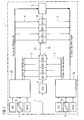
- Fig. 1 shows a two-channel unit 1 with digital Reporting levels MS, which for reasons of security reasons Message level pairs are executed and to a not shown Process connection for the safe operation of a safety-related Furnishings of the indoor facility belong, therefore For example, for the control of signal lamps, turnout drives, Axle counters, free-field devices, speed measuring devices and driving locks as well for safe Contact queries.
- each notification level MSO-MS7 is connected to two controllers 2a, 2b, each Controller 2a, 2b each with an input and an output the reporting level pairs.
- the Controller 2a with the input of a message level MS and the Output of the other reporting level MS connected.
- a test circuit 5 which is based on a command from the controller 2b (testing the reporting levels) all inputs of the reporting levels MSO-MS7 to ground (by the arrows 5a, 5b is the Passing through the test circuit 5 shown), which is a simple Possibility is to change the reporting levels MSO-MS7 to the state Zero.
- the state zero is one of two defined ones Input states of reporting levels MSO-MS7.
- Subsequently are simulated by the two controllers 2a, 2b Input signals to the inputs of all eight reporting levels MSO-MS7 given (testing the reporting levels), as predetermined bit patterns, preferably such bit patterns Be used already for such tests have proven to be successful.
- the output signals of the bit patterns are from the controllers 2a, 2b detected (reading the messages) and are available to the higher-level secure computer (not shown) via the controller 2 available.
- the controllers 2a, 2b communicate with the computer via a serial bus 6, which - as in Fig. 1 by the two diagonal bars - a potential separation 6a has, here by means of two optocouplers (not shown).
- a power loss limitation of the optocoupler provided by the optocouplers below the Nominal operating voltage can be operated and the Operating voltage via series resistors on the optocouplers is applied.
- connection 7 is the parent computer with connected to a switching unit ASS, which from the secure computer directly controlled the supply voltage of the connected Disables the peripheral to its shutdown command (Through the arrows 7a, 7b, the penetration is shown schematically).
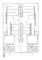
- Fig. 2 shows a two-channel unit with output side digital command levels KS instead of the reporting levels MS. As a comparison of Fig. 1 and Fig. 2 shows immediately, is shown in FIG. 2 no test circuit 5 is present, i. the command levels KS do not need to advance to a defined state for testing be set.
- the controllers 2a, 2b each have a state inversion sequentially to the inputs of the command levels KS, namely from the controller 2b to the command levels KS0 - KS3 and from the controller 2a to the command levels KS4 - KS7, which is referred to in Fig. 2 as controlling the commands is.
- the state inversion takes the form of short pulses, for example voltage pulses, during any current state at each input of the command levels.
- the resulting output signals (pulse signals) are recorded (read back the commands) and the safe Calculator provided.
- a serial bus 6 is for communication with the provided safe computer, in turn, a potential separation 6a by means of optocouplers. Also is one Power loss limitation of the optocouplers provided by operated the optocouplers below the nominal operating voltage and the operating voltage via series resistors to the Optocouplers is present.
- the secure computer can supply the supply voltage the connected peripherals are all connected to the Command levels connectable consumers, such as relays etc., via the switching unit ASS turn off what is through the arrows 7a and 7b is shown, with the arrows 7a and 7b show the penetration of the switching unit ASS.
Landscapes
- Engineering & Computer Science (AREA)
- Physics & Mathematics (AREA)
- General Physics & Mathematics (AREA)
- Automation & Control Theory (AREA)
- Computer Networks & Wireless Communication (AREA)
- Signal Processing (AREA)
- Emergency Protection Circuit Devices (AREA)
- Safety Devices In Control Systems (AREA)
Abstract
Description
Die Erfindung betrifft eine zweikanalige Einheit mit eingangsseitigen
digitalen Meldestufen oder ausgangsseitigen digitalen
Kommandostufen gemäß den Oberbegriffen der Ansprüche
1 und 7.The invention relates to a two-channel unit with input side
digital reporting levels or output digital
Command levels according to the preambles of the
Im sicheren Betrieb arbeitende sicherungstechnische Einrichtungen sind bekannt. Dabei kann es sich um Signallampen, Weichenantriebe, Achszähler, Freimeldereinrichtungen und dergleichen in der Außenanlage eines Stellwerks handeln. Die Innenanlage eines solchen Stellwerks umfasst heute einen übergeordneten sicheren Rechner, der mit einer Vielzahl von weiteren Komponenten der Innenanlage verbunden ist. Bei diesen Komponenten kann es sich um zweikanalige Einheiten entweder mit digitalen Melde- oder Kommandostufen handeln. Diese müssen aus Sicherheitsgründen bezüglich ihrer Funktionsfähigkeit zyklisch überprüft werden. Hierzu verfügt die Einheit für jeden Kanal über einen Controller, der jeweils vom sicheren Rechner steuerbar ist. Die Melde- oder Kommandostufen sind aus Sicherheitsgründen zweikanalig ausgeführt, wobei die beiden Controller jeweils mit einem Eingang und einem Ausgang der beiden Melde- bzw. Kommandostufen eines Paares verbunden sind.Safe working safety equipment are known. These may be signal lamps, turnout drives, Axle counters, emergency signaling devices and the like act in the grounds of a signal box. The indoor unit of such a signal box today includes a parent secure machine that comes with a host of others Components of the indoor system is connected. In these Components can be two-channel units either act with digital notification or command levels. These must for safety reasons regarding their functionality be checked cyclically. The unit has one for each Channel via a controller, each from the safe Computer is controllable. The message or command levels are for safety reasons two channels, whereby the two Controller each with an input and an output the two message or command levels of a pair connected are.
Zur Prüfung der Meldestufen kann eine elektronische Prüfschaltung vorgesehen sein, die von den Controllern so gesteuert wird, dass alle Eingänge der Meldestufen auf Masse gelegt werden können. Danach werden vom Controller vorgeschriebene Bitmuster zur Simulation von digitalen Eingangssignalen auf die Eingänge der Meldestufen gegeben, die dann mit entspredie Eingänge der Meldestufen gegeben, die dann mit entsprechenden Ausgangssignalen reagieren, auf welche der übergeordnete Rechner wiederum über die Controller Zugriff hat.To check the reporting levels, an electronic test circuit be provided, so controlled by the controllers is that all inputs of the reporting levels are grounded can be. After that are prescribed by the controller Bit pattern for the simulation of digital input signals given the inputs of the reporting levels, which then entspredie with Inputs of the reporting levels given, which then with appropriate Output signals respond to which the parent Computer in turn has access via the controller.
Zur Prüfung der Kommandostufen kann von den Controllern jeweils ein zeitlich kurzer Impuls auf die Eingänge der Kommandostufen gegeben werden, und zwar sequentiell, d.h. zeitlich hintereinander jeweils einen Impuls auf einen Eingang. Die Impulse sind so bemessen, dass es an den Eingängen zu einer kurzzeitigen Zustandsinvertierung kommt. Die dadurch kurzzeitig geänderten Ausgangssignale werden wiederum erfasst und dem zugeordneten sicheren Rechner zur Verfügung gestellt.To check the command levels can be from the controllers each a temporally short impulse on the inputs of the command levels be given sequentially, i. chronologically one pulse at a time on one input. The Impulses are sized so that it is at the entrances to a momentary state inversion comes. The short term changed output signals are in turn detected and provided to the associated secure computer.
Aus Sicherheitsgründen ist zwischen dem sicheren Rechner und den Melde- bzw. Kommandostufen eine Potenzialtrennung vorhanden. Bei der bekannten Einheit ist dazu jede Melde- bzw. Kommandostufe mit einer eigenen Potenzialtrennung versehen; hierzu dienen entsprechende Optokoppler.For security reasons is between the secure computer and There is a potential separation for the message or command levels. In the known unit to each message or command level provided with its own potential separation; For this purpose, appropriate optocouplers serve.
Nachteilig bei der bekannten Einheit ist es, dass diese aufgrund der vielen Optokoppler relativ großbauend und teuer ist.A disadvantage of the known unit is that these due the many optocouplers relatively large-scale and expensive is.
Weiter ist aus der DE 198 13 389 C2 bereits eine sicherheitsgerichtete Ansteuerschaltung mit zwei Transceivern A und B bekannt, welche die beiden Kanäle der Schaltung bilden. Am Eingang der Ansteuerschaltung sind Meldestufen in digitaler Form vorgesehen. Ein übergeordneter Master steuert zwei Stationen bzw. Controller CPU A und CPU B; diese sind jeweils mit einem Eingang und einem Ausgang der Meldestufen verbunden, welche zweikanalig ausgebildet sind. Zur Prüfung können die Eingänge der Meldestufen von den Controllern CPU A, CPU B auf einen definierten Zustand gesetzt und simulierte Eingangssignale auf die Eingänge gegeben werden. Diese so bewirkten Ausgangssignale werden durch Anwendersoftware erfasst und dem übergeordneten Master zur Verfügung gestellt. Die Controller CPU A, CPU B kommunizieren mit dem Master über voneinander getrennte und unabhängige serielle Busse. Dabei weist jeder serielle Bus eine Potentialtrennung auf, die mittels Optokopplern bewirkt wird.Furthermore, from DE 198 13 389 C2 already a Safety-related control circuit with two transceivers A and B known which the two channels of the circuit form. At the input of the control circuit are reporting levels in digital form provided. A parent master controls two stations or controllers CPU A and CPU B; these are each with an input and an output of the reporting levels connected, which are formed two channels. For testing The inputs of the reporting levels can be from the controllers CPU A, CPU B set to a defined state and simulated Input signals are given to the inputs. This way caused output signals are by user software captured and made available to the parent master. The controller CPU A, CPU B communicate with the master via separate and independent serial buses. there Each serial bus has a potential separation, the is effected by means of optocouplers.
Die Melde- und Kommandostufen der Ein-/Ausgangsebene sind so aufgebaut, dass sie sowohl als Ein- und Ausgänge als auch zur Anbindung weiterer serieller Bus-Systeme verwendbar sind. Auf diese Weise ermöglicht es die Verschaltung der Ein/Ausgangspaare, diese mit Hilfe von Testmustern zu prüfen sowie die Anschlüsse in definierte Zustände zu schalten. Die Melde- und Kommandostufen können folglich über ein duales, redundantes Bussystem mit einem übergeordneten sicheren Master so verbunden werden, dass alle Bezugspotentiale voneinander getrennt sind.The message and command levels of the input / output level are the same built that they both as inputs and outputs as well as for Connection of other serial bus systems can be used. On this way it allows the interconnection of the input / output pairs, to check these with the help of test patterns as well as switching the connections to defined states. The Message and command levels can therefore be controlled by a dual, redundant bus system with a higher-level safe Master be connected so that all reference potentials are separated from each other.
Bezüglich der Spannungsfestigkeit sind zwei Trennebenen vorhanden, eine im Bus am Master und die andere in den Ausgangsstufen (Ausgabestufen).Regarding the dielectric strength are two parting planes present, one in the bus at the master and the other in the bus Output levels (output levels).
Letzteres bedeutet, dass im Fehlerfall die sichere Trennung, die hier zwingend erforderlich ist, verlorengeht.The latter means that in case of error the secure separation, which is absolutely necessary here, is lost.
Die Aufgabe der Erfindung ist es, die Potentialtrennung mittels Optokopplern auch im Fehlerfall sicherzustellen.The object of the invention is the potential separation using optocouplers to ensure even in case of error.
Die Lösung dieser Aufgabe wird durch die in den Ansprüchen 1
und 7 angegebenen Merkmale gegeben. Die kennzeichnenden Merkmale
der Unteransprüche enthalten entsprechende vorteilhafte
Ausgestaltungen.The solution to this problem is solved by the in the
Die Lösung sieht bezüglich der Einheit mit digitalen Meldestufen vor, dass eine Verlustleistungsbegrenzung der Optokoppler vorgesehen ist. Die Verwendung eines seriellen Busses ermöglicht hier vorteilhafterweise den Einbau der Potenzialtrennung in den Bus, was trotz einer größeren Zahl von Melde- oder Kommandostufen eine kleinbauende Ausführung ergibt, aufgrund der Einsparung von einer Vielzahl von Optokopplern, was darüber hinaus auch kostengünstig ist. Aber erst durch die Verlustleistungsbegrenzung der Optokoppler ist die Potentialtrennung auch im Fehlerfall sichergestellt. Dies wird mit einfachen Mitteln dadurch erreicht, dass die Optokoppler zur Verlustleistungsbegrenzung unterhalb der Nennbetriebsspannung betrieben werden und die Betriebsspannung über entsprechend dimensionierte Vorwiderstände an den Optokopplern anliegt.The solution looks at the unit with digital reporting levels suggest that a power loss limitation of Optocoupler is provided. The use of a serial Buses here advantageously allows the installation of the Electrical isolation in the bus, which despite a larger number of notification or command levels a small construction execution results, due to the saving of a variety of Optocouplers, which is also inexpensive. But only by the power loss limitation of the optocoupler is the potential separation is ensured even in the event of a fault. This is achieved by simple means that the Optocouplers for power loss limitation below the Nominal operating voltage can be operated and the Operating voltage via appropriately dimensioned Resistor connected to the optocouplers.
Technisch einfach ist es, alle Eingänge auf den Zustand Null zu setzen.It is technically simple, all inputs to the state zero to put.
Insbesondere wird die Prüfung vereinfacht, wenn die Eingänge der stromsensitiven Meldestufen auf Masse gelegt werden.In particular, the test is simplified when the inputs the current-sensitive reporting levels are grounded.
Eine einfache Sicherheitsschaltung sieht vor, dass eine vom Rechner gesteuerte Schalteinheit vorgesehen ist, welche im Fehlerfall die Versorgungsspannung der angeschlossenen Peripherie abschaltet.A simple security circuit provides that one of the Computer controlled switching unit is provided which in the Error, the supply voltage of the connected peripherals off.
Die Prüfqualität wird erhöht, wenn die auf die Eingänge gegebenen simulierten digitalen Eingangssignale vorgegebene Bitmuster sind, und zwar solche, welche sich bei der Prüfung von Meldestufen bewährt haben.The test quality is increased when the inputs given to the inputs simulated digital input signals predetermined bit pattern are, and those, which are in the examination of Have proven to be effective.
Die Lösung sieht auch bezüglich der zweikanaligen Einheit mit digitalen Kommandostufen vor, dass eine Verlustleistungsbegrenzung der Optokoppler vorgesehen ist.The solution also includes the two-channel unit digital command levels before that one Power loss limitation of the optocoupler is provided.
Bei einer technisch einfachen Einheit wird die Zustandsinvertierung impulsartig durchgeführt, der logische Zustand der Kommandostufen wird also impulsartig verändert.In a technically simple unit, the state inversion becomes pulsed, the logical state of the Command levels are changed so impulsively.
Insbesondere wird die Prüfung vereinfacht, wenn zur Verlustleistungsbegrenzung die Optokoppler unterhalb der Nennbetriebsspannung betrieben werden und die Betriebsspannung über Vorwiderstände an den Optokopplern anliegt.In particular, the test is simplified if for Power loss limiting the optocouplers below the Nominal operating voltage can be operated and the Operating voltage via series resistors on the optocouplers is applied.
Eine Sicherheitsabschaltung ist gewährleistet, wenn eine vom Rechner gesteuerte Schalteinheit vorgesehen ist, welche im Fehlerfall die Versorgungsspannung der angeschlossenen Peripherie abschaltet.A safety shutdown is guaranteed if one of the Computer controlled switching unit is provided which in the Error, the supply voltage of the connected peripherals off.
Die Erfindung nachfolgend anhand einer Zeichnung näher beschrieben. Es zeigen:
- Fig. 1
- eine zweikanalige Einheit mit vier Meldestufenpaaren und
- Fig. 2
- eine zweikanalige Einheit mit vier digitalen Kommandostufenpaaren.
- Fig. 1
- a two - channel unit with four reporting level pairs and
- Fig. 2
- a two-channel unit with four digital command level pairs.
Die Fig. 1 zeigt eine zweikanalige Einheit 1 mit digitalen
Meldestufen MS, die aus sicherungstechnischen Gründen als
Meldestufenpaare ausgeführt sind und zu einer nicht gezeigten
Prozessanschaltung für das sichere Betreiben einer sicherungstechnischen
Einrichtung der Innenanlage gehören, also
beispielsweise für die Ansteuerung von Signallampen, Weichenantrieben,
Achszählern, Freimeldeeinrichtungen, Geschwindigkeitsmesseinrichtungen
und Fahrsperren als auch für sichere
Kontaktabfragen.Fig. 1 shows a two-
Eingangsseitig sind in Fig. 1 vier Meldestufenpaare MS0, MS4;
MS1, MS5; MS2, MS6 und MS3, MS7 vorgesehen; die Meldestufen
(MSO-MS7) sind also zweikanalig vorhandenen. Jede Meldestufe
MSO-MS7 ist mit zwei Controllern 2a, 2b verbunden, jeder
Controller 2a, 2b jeweils mit einem Eingang und einem Ausgang
der Meldestufenpaare. An jedem Meldestufenpaar ist also der
Controller 2a mit dem Eingang der einen Meldestufe MS und dem
Ausgang der anderen Meldestufe MS verbunden. Dabei repräsentieren
die von den Meldestufen MSO-MS7 wegführenden Pfeile 3
in Fig. 1 die Ausgänge und die hinführenden Pfeile 4 die Eingänge
der Meldestufen MSO-MS7. In Fig. 1 ist der Controller
2a mit den Eingängen der Meldestufen MS4 - MS7 und den Ausgängen
der Meldestufen MS0 - MS3 verbunden, umgekehrt der
Controller 2b mit den Ausgängen der Meldestufen MS4 - MS7 und
den Eingängen der Meldestufen MS0 - MS3.On the input side, in FIG. 1, four signaling stage pairs MS0, MS4;
MS1, MS5; MS2, MS6 and MS3, MS7 provided; the reporting levels
(MSO-MS7) are therefore two-channel existing. Each notification level
MSO-MS7 is connected to two
Zur Prüfung der stromsensitiven Meldestufen MSO-MS7 dient
eine Prüfschaltung 5, welche auf einen Befehl des Controllers
2b hin (Testen der Meldestufen) alle Eingänge der Meldestufen
MSO-MS7 auf Masse legt (durch die Pfeile 5a, 5b ist der
Durchgriff der Prüfschaltung 5 dargestellt), was eine einfache
Möglichkeit ist, um die Meldestufen MSO-MS7 auf den Zustand
Null zu setzen. Der Zustand Null ist einer von zwei definierten
Eingangszuständen der Meldestufen MSO-MS7. Anschließend
werden von den beiden Controllern 2a, 2b simulierte
Eingangssignale auf die Eingänge aller acht Meldestufen
MSO-MS7 gegeben (Testen der Meldestufen), und zwar als
vorgegebene Bitmuster, wobei vorzugsweise solche Bitmuster
verwendet werden, die sich bereits für derartige Prüfungen
bewährt haben. Die Ausgangssignale der Bitmuster werden von
den Controllern 2a, 2b erfasst (Einlesen der Meldungen) und
stehen dem übergeordneten sicheren Rechner (nicht gezeigt)
über die Controller 2 zur Verfügung.To test the current-sensitive reporting levels MSO-MS7 is used
a
Die Controller 2a, 2b kommunizieren mit dem Rechner über
einen seriellen Bus 6, der - wie in Fig. 1 durch die beiden
diagonalen Striche gekennzeichnet - eine Potenzialtrennung 6a
aufweist, hier mittels zweier Optokoppler (nicht gezeigt).
Dabei ist eine Verlustleistungsbegrenzung der Optokoppler
vorgesehen, indem die Optokoppler unterhalb der
Nennbetriebsspannung betrieben werden und die
Betriebsspannung über Vorwiderstände an den Optokopplern
anliegt.The
Über eine Verbindung 7 ist der übergeordnete Rechner mit
einer Schalteinheit ASS verbunden, welche vom sicheren Rechner
direkt gesteuert die Versorgungsspannung der angeschlossenen
Peripherie auf dessen Abschaltbefehl hin abschaltet
(durch die Pfeile 7a, 7b ist der Durchgriff schematisch dargestellt).About a
Fig. 2 zeigt eine zweikanalige Einheit mit ausgangsseitigen
digitalen Kommandostufen KS anstelle der Meldestufen MS. Wie
ein Vergleich von Fig. 1 und Fig. 2 sofort zeigt, ist in Fig.
2 keine Prüfschaltung 5 vorhanden, d.h. die Kommandostufen KS
müssen zur Prüfung nicht vorher auf einen definierten Zustand
gesetzt werden.Fig. 2 shows a two-channel unit with output side
digital command levels KS instead of the reporting levels MS. As
a comparison of Fig. 1 and Fig. 2 shows immediately, is shown in FIG.
2 no
Zur Prüfung wird von den Controllern 2a, 2b jeweils eine Zustandsinvertierung
sequentiell auf die Eingänge der Kommandostufen
KS gegeben, und zwar vom Controller 2b auf die Kommandostufen
KS0 - KS3 und vom Controller 2a auf die Kommandostufen
KS4 - KS7, was in Fig. 2 als Steuern der Kommandos bezeichnet
ist. Die Zustandsinvertierung erfolgt in Form von
kurzen Impulsen, beispielsweise Spannungsimpulsen, während
eines beliebigen aktuellen Zustands an jedem Eingang der Kommandostufen.
Die so bewirkten Ausgangssignale (Impulssignale)
werden erfasst (Rücklesen der Kommandos) und dem sicheren
Rechner zur Verfügung gestellt.For checking, the
Auch hier ist ein serieller Bus 6 zur Kommunikation mit den
sicheren Rechner vorgesehen, der wiederum eine Potenzialtrennung
6a mittels Optokopplern aufweist. Ebenfalls ist eine
Verlustleistungsbegrenzung der Optokoppler vorgesehen, indem
die Optokoppler unterhalb der Nennbetriebsspannung betrieben
werden und die Betriebsspannung über Vorwiderstände an den
Optokopplern anliegt.Again, a
Im Bedarfsfall kann der sichere Rechner die Versorgungsspannung
der angeschlossenen Peripherie, das sind alle an die
Kommandostufen anschließbaren Verbraucher, beispielsweise Relais
usw., über die Schalteinheit ASS abschalten, was durch
die Pfeile 7a und 7b dargestellt ist, wobei die Pfeile 7a und
7b den Durchgriff der Schalteinheit ASS zeigen sollen. If necessary, the secure computer can supply the supply voltage
the connected peripherals are all connected to the
Command levels connectable consumers, such as relays
etc., via the switching unit ASS turn off what is through
the
- 11
- zweikanalige Einheittwo-channel unit
- 2a2a
- Controllercontroller
- 2b2 B
- Controllercontroller
- 33
- Ausgangoutput
- 44
- Eingangentrance
- 55
- Prüfschaltungtest circuit
- 5a, 5b5a, 5b
- Durchgriff der PrüfschaltungPenetration of the test circuit
- 66
- serieller Busserial bus
- 6a6a
- PotenzialtrennungElectrical isolation
- 77
- Verbindungconnection
- 7a, b7a, b
- Durchgriff der ASSPenetration of the ASA
- MSMS
- digitale Meldestufedigital reporting level
- KSKS
- digitale Kommandostufedigital command level
- ASSASS
- Schalteinheitswitching unit
Claims (10)
mit zwei von einem übergeordneten sicheren Rechner steuerbaren Controllern (2a, 2b), die jeweils mit einem Eingang (4) und einem Ausgang (3) der zweikanalig vorhandenen Meldestufen (MSO-MS7) verbunden sind,
mit einer Prüfschaltung (5), welche zur Prüfung der Meldestufen (MSO-MS7) von den Controllern (2a, 2b) gesteuert alle Eingänge der Meldestufen (MSO-MS7) auf einen definierten Zustand setzt, wobei anschließend von den beiden Controllern (2a, 2b) simulierte Eingangssignale auf die Eingänge (4) gegeben und die so bewirkten Ausgangssignale erfasst und dem übergeordneten Rechner zur Verfügung gestellt werden,
wobei die Controller (2a, 2b) und der Rechner über voneinander getrennte unabhängige serielle Busse (6) miteinander kommunizieren,
jeder serielle Bus (6) eine Potenzialtrennung (6a) aufweist und
zur Potenzialtrennung (6a)in den seriellen Bussen (6) Optokoppler verwendet werden,
dadurch gekennzeichnet, dass eine Verlustleistungsbegrenzung der Optokoppler vorgesehen ist.Dual-channel unit (1) with input-side digital reporting levels (MSO-MS7) for a safe-operated safety equipment,
with two controllers (2a, 2b) controllable by a higher-level secure computer, which are each connected to an input (4) and an output (3) of the two-channel reporting levels (MSO-MS7),
with a test circuit (5) which controls all inputs of the reporting stages (MSO-MS7) to a defined state for checking the reporting levels (MSO-MS7) of the controllers (2a, 2b), wherein subsequently by the two controllers (2a, 2b) simulated input signals are applied to the inputs (4) and the resulting output signals are detected and made available to the higher-level computer,
wherein the controllers (2a, 2b) and the computer communicate with each other via separate independent serial buses (6),
each serial bus (6) has a potential separation (6a) and
for electrical isolation (6a) in the serial buses (6) optocouplers are used
characterized in that a power dissipation limitation of the opto-couplers is provided.
dadurch gekennzeichnet, dass zur Verlustleistungsbegrenzung die Optokoppler unterhalb der Nennbetriebsspannung betrieben werden und die Betriebsspannung über Vorwiderstände an den Optokopplern anliegt.Two-channel unit (1) according to claim 1,
characterized in that for loss of power limitation, the opto-couplers are operated below the nominal operating voltage and the operating voltage applied via series resistors to the optocouplers.
dadurch gekennzeichnet, dass alle Eingänge (4) auf den Zustand Null gesetzt werden.Two-channel unit (1) according to claim 1 or 2,
characterized in that all inputs (4) are set to the state zero.
dadurch gekennzeichnet, dass die Eingänge (4) der stromsensitiven Meldestufen (MS= - MS7) auf Masse gelegt werden.Two-channel unit (1) according to claim 3,
characterized in that the inputs (4) of the current-sensitive reporting levels (MS = - MS7) are grounded.
dadurch gekennzeichnet, dass eine vom Rechner gesteuerte Schalteinheit vorgesehen ist, welche im Fehlerfall die Versorgungsspannung der angeschlossenen Peripherie abschaltet.Two-channel unit (1) according to one of claims 1 - 4,
characterized in that a computer-controlled switching unit is provided, which switches off the supply voltage of the connected peripherals in case of failure.
dadurch gekennzeichnet, dass die auf die Eingänge (4) gegebenen simulierten digitalen Eingangssignale vorgegebene Bitmuster sind.Two-channel unit (1) according to one of claims 1 - 5,
characterized in that the simulated digital input signals given to the inputs (4) are predetermined bit patterns.
mit zwei von einem übergeordneten sicheren Rechner steuerbaren Controllern (2a, 2b), die jeweils mit einem Eingang (4) und einem Ausgang (3) der paarweise vorhandenen Kommandostufen (KSO-KS7) verbunden sind,
wobei zu deren Prüfung von den Controllern (2a, 2b) jeweils eine Zustandsinvertierung sequentiell auf die Eingänge (4) der Kommandostufen (KSO-KS7) gegeben wird und die so bewirkten Ausgangssignale erfasst und dem Rechner zur Verfügung gestellt werden,
wobei die Controller (2a, 2b) und der Rechner über voneinander getrennte unabhängige serielle Busse (6) miteinander kommunizieren,
jeder serielle Bus (6) eine Potenzialtrennung (6a) aufweist und
zur Potenzialtrennung (6a)in den seriellen Bussen (6) Optokoppler verwendet werden,
dadurch gekennzeichnet, dass eine Verlustleistungsbegrenzung der Optokoppler vorgesehen ist.Two-channel unit (1) with digital command levels on the output side for a safe operation of the indoor unit
with two controllers (2a, 2b) which can be controlled by a higher-level secure computer and which are each connected to an input (4) and an output (3) of the paired command levels (KSO-KS7),
wherein for their examination by the controllers (2a, 2b) in each case a state inversion is given sequentially to the inputs (4) of the command levels (KSO-KS7) and the resulting output signals are detected and made available to the computer,
wherein the controllers (2a, 2b) and the computer communicate with each other via separate independent serial buses (6),
each serial bus (6) has a potential separation (6a) and
for electrical isolation (6a) in the serial buses (6) optocouplers are used
characterized in that a power dissipation limitation of the opto-couplers is provided.
dadurch gekennzeichnet, dass die Zustandsinvertung impulsartig erfolgt.Two-channel unit (1) according to claim 7,
characterized in that the state inversion is pulse-like.
dadurch gekennzeichnet, dass zur Verlustleistungsbegrenzung die Optokoppler unterhalb der Nennbetriebsspannung betrieben werden und
die Betriebsspannung über Vorwiderstände an den Optokopplern anliegt.Two-channel unit (1) according to claim 7 or 8,
characterized in that the loss power limitation, the optocouplers are operated below the rated operating voltage and
the operating voltage is applied to the optocouplers via series resistors.
dadurch gekennzeichnet, dass eine vom Rechner gesteuerte Schalteinheit (ASS) vorgesehen ist, welche im Fehlerfall die Versorgungsspannung der angeschlossenen Peripherie abschaltet.Two-channel unit (1) according to one of claims 7 - 9,
characterized in that a computer-controlled switching unit (ASS) is provided, which switches off the supply voltage of the connected peripherals in case of failure.
Applications Claiming Priority (2)
| Application Number | Priority Date | Filing Date | Title |
|---|---|---|---|
| DE10355863 | 2003-11-25 | ||
| DE10355863 | 2003-11-25 |
Publications (1)
| Publication Number | Publication Date |
|---|---|
| EP1536301A2 true EP1536301A2 (en) | 2005-06-01 |
Family
ID=34442354
Family Applications (1)
| Application Number | Title | Priority Date | Filing Date |
|---|---|---|---|
| EP20040090407 Withdrawn EP1536301A2 (en) | 2003-11-25 | 2004-10-22 | Two-channel unit with digital signalling input stage and digital control output stage |
Country Status (2)
| Country | Link |
|---|---|
| EP (1) | EP1536301A2 (en) |
| CA (1) | CA2488160A1 (en) |
Cited By (1)
| Publication number | Priority date | Publication date | Assignee | Title |
|---|---|---|---|---|
| CN101137181B (en) * | 2007-10-09 | 2010-06-09 | 中兴通讯股份有限公司 | Load testing method and device |
-
2004
- 2004-10-22 EP EP20040090407 patent/EP1536301A2/en not_active Withdrawn
- 2004-11-23 CA CA 2488160 patent/CA2488160A1/en not_active Abandoned
Cited By (1)
| Publication number | Priority date | Publication date | Assignee | Title |
|---|---|---|---|---|
| CN101137181B (en) * | 2007-10-09 | 2010-06-09 | 中兴通讯股份有限公司 | Load testing method and device |
Also Published As
| Publication number | Publication date |
|---|---|
| CA2488160A1 (en) | 2005-05-25 |
Similar Documents
| Publication | Publication Date | Title |
|---|---|---|
| DE60110435T2 (en) | ELECTRONIC SAFETY SYSTEM FOR TRAVEL STAIRCASE | |
| EP0875810B1 (en) | Method and device for monitoring an installation with several function units | |
| EP3069202B1 (en) | Safety control system having configurable inputs | |
| DE19643092C2 (en) | Field data bus system | |
| DE10353950C5 (en) | control system | |
| EP0082859B1 (en) | Antiblocking regulator system | |
| EP0742500A2 (en) | Fail-safe touch-switch functions and switch functions with error avoidance | |
| EP0007579B1 (en) | Circuit arrangement for monitoring the state of signalling systems, especially traffic light signalling systems | |
| EP0004909B1 (en) | Annunciator of danger | |
| DE102013106739A1 (en) | Safety switching device with fail-safe inputs | |
| DE102005055428A1 (en) | Bus module for connection to a bus system and use of such a bus module in an AS-i bus system | |
| DE102016000126A1 (en) | Serial bus system with coupling modules | |
| DE102013102998A1 (en) | Safety signal processing system | |
| EP3100121B1 (en) | Method and apparatus for safely disconnecting an electrical load | |
| DE102007048122A1 (en) | Device and method for actuator monitoring of a two-channel connected safety-related load circuit | |
| DE2029874B2 (en) | Monitoring circuit | |
| EP2375636A1 (en) | Device and method for configuring a bus system | |
| EP3745217A1 (en) | Method and device for monitoring the data processing and data transmission in a safety system | |
| EP0429972B1 (en) | Apparatus and method for monitoring navigation equipment | |
| EP1672446A2 (en) | Secure Input/Ouput assembly for a controller | |
| EP3133447B1 (en) | Safety switch | |
| EP3557598A1 (en) | Safety switch | |
| EP0059789B1 (en) | Device for testing the functions of a multi-computer system | |
| EP1536301A2 (en) | Two-channel unit with digital signalling input stage and digital control output stage | |
| EP4046339A1 (en) | Safe test arrangement |
Legal Events
| Date | Code | Title | Description |
|---|---|---|---|
| PUAI | Public reference made under article 153(3) epc to a published international application that has entered the european phase |
Free format text: ORIGINAL CODE: 0009012 |
|
| AK | Designated contracting states |
Kind code of ref document: A2 Designated state(s): AT BE BG CH CY CZ DE DK EE ES FI FR GB GR HU IE IT LI LU MC NL PL PT RO SE SI SK TR |
|
| AX | Request for extension of the european patent |
Extension state: AL HR LT LV MK |
|
| STAA | Information on the status of an ep patent application or granted ep patent |
Free format text: STATUS: THE APPLICATION IS DEEMED TO BE WITHDRAWN |
|
| 18D | Application deemed to be withdrawn |
Effective date: 20100501 |