EP1536157B1 - Cable connector - Google Patents
Cable connector Download PDFInfo
- Publication number
- EP1536157B1 EP1536157B1 EP04026540.7A EP04026540A EP1536157B1 EP 1536157 B1 EP1536157 B1 EP 1536157B1 EP 04026540 A EP04026540 A EP 04026540A EP 1536157 B1 EP1536157 B1 EP 1536157B1
- Authority
- EP
- European Patent Office
- Prior art keywords
- cable
- cable connector
- body part
- another
- cable sections
- Prior art date
- Legal status (The legal status is an assumption and is not a legal conclusion. Google has not performed a legal analysis and makes no representation as to the accuracy of the status listed.)
- Active
Links
Images

Classifications
-
- F—MECHANICAL ENGINEERING; LIGHTING; HEATING; WEAPONS; BLASTING
- F16—ENGINEERING ELEMENTS AND UNITS; GENERAL MEASURES FOR PRODUCING AND MAINTAINING EFFECTIVE FUNCTIONING OF MACHINES OR INSTALLATIONS; THERMAL INSULATION IN GENERAL
- F16G—BELTS, CABLES, OR ROPES, PREDOMINANTLY USED FOR DRIVING PURPOSES; CHAINS; FITTINGS PREDOMINANTLY USED THEREFOR
- F16G11/00—Means for fastening cables or ropes to one another or to other objects; Caps or sleeves for fixing on cables or ropes
- F16G11/10—Quick-acting fastenings; Clamps holding in one direction only
Definitions
- the invention relates to a cable connector for connecting non-intersecting cable sections of at least one cable according to the feature configuration of the preamble of claim 1.
- DE 41 00 944 C1 is a chair with a formed of flexible cable sections covering at least one carrier for forming the contact surface in the region of the backrest and / or the seat in the region of the seat known, said immediately adjacent cable sections in their longitudinal direction at a distance from each other to form a planar network arrangement with diamond-shaped mesh connected to each other.
- the pertinent cable sections are formed of wire ropes or metallic strands, and for permanent connection of the non-intersecting cable sections serve at the connection or node points by external force verpreßbare sleeve-like connecting parts, in particular in the form of compression sleeves or ferrules.
- the pertinent ferrules or ferrules form in laterally closed connecting parts, which have at their front sides free opening cross-sections for introducing or threading the cable sections of the string network arrangement to be joined together.
- these are thus within the network arrangement at their respective connection position partially over the entire length of the network to guide and position, and then then with a suitable press tool to connect the cable for connecting each other in pairs arranged cable sections kraftbmony.
- the DE 199 34 240 A1 a cable connector for the permanent connection of non-intersecting cable sections, which has a first component and a permanent component designed for permanent connection to the second component, wherein the two said components in the manner of a riveted joint are connected to each other and adapted to the cable sections, that the male and adjacent adjacent cable sections are fixed in a clamping manner in recesses on the cable connector.
- a cable connector (Fig. 16) for connecting non-intersecting cable sections at least a cable which can be connected to each other by means of the fixed mounting state laterally closed, sleeve-like connecting parts, wherein the respective connecting part in the initial state before assembly consists of two main body parts, which have lateral insertion openings for inserting the interconnected cable sections, wherein at each end of the respective main body part a connecting means is provided and wherein in the fixed mounting state, the connecting means of the basic body parts used in each case are in communication.
- FR-A-2 784 729 a generic cable connector for connecting non-intersecting cable sections of at least one rope is known, in particular for forming joints of a flat expandable, flexible network arrangement with interconnected at cable sections cable sections, which are connected by means of the fixed mounting state laterally closed, sleeve-like connecting parts, wherein the respective connecting part in the initial state before assembly and in the specified mounting state of a Basic body part is made, which has a lateral insertion opening for inserting the interconnected cable sections.
- each one free end of the main body part is bent obliquely, so that at the two ends mutually corresponding groove-like locking projections arise, which are locked together or verclipbar closing the terminal-like cable connector, then along the linear connection point of the main body part a continuous strip-like projection is formed, and then from the outside the pertinent detent or clip connection can also unintentionally solve again, and then releases the cable connector.
- the known design is expensive and expensive to manufacture and even when high connection forces occur can already solve the mentioned strip-shaped detent or clip connection.
- the present invention seeks to ensure the known cable connector while maintaining its advantages, namely high connection forces, to further improve that at least the Netzhers republic is largely automated, is easy and inexpensive to accomplish, and the length of Networks can be varied arbitrarily.
- a related object solves a cable connector with the features of claim 1 in its entirety.
- the base body part at one end has a latching recess as the one connecting means into which a zuordenbares locking member at the opposite end as a further connection means of the main body part is inserted in register in such a way that a self-contained fixing sleeve or press terminal is formed as soon as the terminal-like cable connector is closed to the sleeve, the cable connector according to the invention is realized with only one main body part, so that in this respect the connection technology according to the invention for the creation of network arrangements can be implemented very cost effective.
- the respective cable connector can be fixed to almost any predetermined connection points of the network arrangement to the adjacent assignable cable sections, the pertinent locking process can be automated, but can still be made by hand, especially if only small areas of network arrangements are needed.
- the hooking means which engage in one another along a separating seam, to one another via a weld seam. Due to the above interlocking means of a basic body part can be in any case such for the sleeve cable connector not only a frictional, but also realize a form-locking connection, which has a favorable effect on the introduction of force, starting from the cable sections on the cable connector itself. If the connecting means is additionally finished with the weld, a cohesive connection is realized in addition to the positive connection.
- the locking part has at least one undercut, in particular in the manner of a step, a trapezoid, an omega or in crenellated or s-shaped training.
- the necessary connection can be produced in a wide range in this way.
- the Fig. 1 shows a section of a designated as a whole with 10 extensible, flexible network arrangement.
- the pertinent net assembly 10 is partially wrapped around a frame 12 to fix the net.
- the pertinent frame 12 may be part of a piece of furniture or a building.
- rope net arrangements according to the Fig. 1 use as a railing filling, as fall protection for buildings, as protection nets, for greening of facades, zoo and fair architecture or in general in the design and furniture sector, as well as for networks in the technical field.
- Fig. 1 shown net is formed from individual cable sections 14 at least one rope, wherein adjacent, non-crossing cable sections 14 can be set to form knot-like joints by means of the cable connector together.
- the respective cable connector forms a sleeve-like connecting part 16, at its two opposite end faces 18 (see. Fig. 2 and 3f ) to connect Enter and exit pairs of cable sections 14.
- the respective connecting part 16 is in the initial state prior to assembly as in the Fig. 1 is shown, from a basic body part 20 (see. Fig. 2 ), which has a lateral insertion opening 22 for inserting the interconnectable cable sections 14.
- At the two opposite ends 24, 26 at least one connecting means 28 is provided for the main body part 20 and in the fixed mounting state, the adjacent opposite connecting means 28 of a main body part 20 with each other.
- the respective connecting means 28 is formed from a Verhakungsmittel 32, wherein the base body part 20 at its two opposite ends 24, 26 has the pertinent interlocking means 32.
- the body portion 20 may be formed of a flat or curved band, preferably of a steel or stainless steel sheet; but may also consist of another material, in particular plastic material, depending on the forces to be absorbed.
- the respective base body portion 20 at its one end 26 has a latching recess 34 into which a zuordenbares locking member 36 is inserted in register, as soon as the terminal-like cable connector is closed to the sleeve.
- the locking member 36 are brought into engagement with the assignable locking recess 34 and in a further process step, the pertinent composite is then pressed onto the introduced into the lateral opening 22 two adjacent cable sections 14, so that such a force as both also form-fitting clamping connection arises.
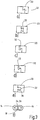
- T-joint solution with concave and convex textured abutment surfaces is the hooking 32 after the Fig. 3a step-like and after the Fig. 3b trapezoidal.
- the Fig. 3c and 3d show crenellated or S-shaped interlocking means 32 and in the solution according to the Fig. 3e the pertinent interlocking means 32 is realized with an omega-shaped latching part 36.
- the interlocking solution shown in the figures can have a plurality of latching parts (not shown) along the two ends 24, 26 in multiple successive arrangement.
- Anchoring solutions exemplified is common to all an undercut, which has a pliers-like clamping grip result, which has a significant increase in strength in the transverse direction compared to the open terminals on the market result; So an increase in strength in the direction transverse to the inlet and outlet of the cable sections in the cable connector according to the invention.
- a kind of open terminal is realized in the pre-assembled state, which can be used for pairwise fixing of cable sections or ropes, and in contrast to the conventionally known terminals is characterized in that a special form when fixing the clamp on the assignable cable sections in addition to the frictional engagement and a positive engagement or a fabric bond or a combination of material bond and positive engagement is achieved, which gives the clamp connection additional strength in the cable transverse direction, so in that extent the strength values of a closed terminal can be achieved.
Description
Die Erfindung betrifft einen Seilverbinder zur Verbindung von einander nicht überkreuzenden Seilabschnitten mindestens eines Seils gemäß der Merkmalsausgestaltung des Oberbegriffes des Patentanspruches 1.The invention relates to a cable connector for connecting non-intersecting cable sections of at least one cable according to the feature configuration of the preamble of claim 1.
Durch die
Um diesen Nachteilen zu begegnen, schlägt die
Durch die
Weitere Seilverbinder sind durch die Entgegenhaltungen
Durch die
Bei der bekannten Lösung ist das jeweils eine freie Ende des Grundkörperteils schräg abgekröpft, so dass an den beiden Enden jeweils zueinander korrespondierende rinnenartige Rastvorsprünge entstehen, die unter Schließen des klemmenartigen Seilverbinders miteinander verrastbar oder verclipbar sind, wobei dann entlang der linienartigen Verbindungsstelle des Grundkörperteils ein durchgehend leistenartiger Vorsprung gebildet ist, und wobei dann von außen her die dahingehende Rast- oder Clipsverbindung sich auch ungewollt wieder lösen kann, und dann den Seilverbinder frei gibt. Auch ist die bekannte Ausgestaltung teuer und aufwändig in der Herstellung und auch beim Auftreten hoher Verbindungskräfte kann sich bereits die angesprochene leistenförmige Rast- oder Clipverbindung lösen.In the known solution, each one free end of the main body part is bent obliquely, so that at the two ends mutually corresponding groove-like locking projections arise, which are locked together or verclipbar closing the terminal-like cable connector, then along the linear connection point of the main body part a continuous strip-like projection is formed, and then from the outside the pertinent detent or clip connection can also unintentionally solve again, and then releases the cable connector. Also, the known design is expensive and expensive to manufacture and even when high connection forces occur can already solve the mentioned strip-shaped detent or clip connection.
Ausgehend von diesem Stand der Technik liegt der Erfindung die Aufgabe zugrunde, die bekannten Seilverbinder unter Beibehalten ihrer Vorteile, nämlich hohe Verbindungskräfte sicherzustellen, dahingehend weiter zu verbessern, dass jedenfalls die Netzhersteilung weitgehend automatisierbar ist, einfach und kostengünstig zu bewerkstelligen ist, sowie die Länge der Netze beliebig variiert werden kann. Eine dahingehende Aufgabe löst ein Seilverbinders mit den Merkmalen des Patentanspruches 1 in seiner Gesamtheit.Based on this prior art, the present invention seeks to ensure the known cable connector while maintaining its advantages, namely high connection forces, to further improve that at least the Netzhersteilung is largely automated, is easy and inexpensive to accomplish, and the length of Networks can be varied arbitrarily. A related object solves a cable connector with the features of claim 1 in its entirety.
Dadurch, dass gemäß dem kennzeichnenden Teil des Patentanspruches 1 das Grundkörperteil an seinem einen Ende eine Rastausnehmung als das eine Verbindungsmittel aufweist, in die ein zuordenbares Rastteil am gegenüberliegenden Ende als weiteres Verbindungsmittel des Grundkörperteils derart paßgenau einbringbar ist, dass eine in sich geschlossene Festlegehülse oder Pressklemme ausgebildet ist, sobald der klemmenartige Seilverbinder zur Hülse geschlossen ist, ist der erfindungsgemäße Seilverbinder mit nur einem Grundkörperteil realisiert, so dass sich insoweit die erfindungsgemäße Verbindungstechnologie zur Erstellung von Netzanordnungen ausgesprochen kostengünstig realisieren läßt. Der jeweilige Seilverbinder ist an nahezu beliebig vorgebbaren Verbindungsstellen der Netzanordnung an den benachbart zuordenbaren Seilabschnitten festlegbar, wobei der dahingehende Festlegevorgang automatisierbar ist, aber nach wie vor auch von Hand vorgenommen werden kann, insbesondere wenn nur kleine Flächen an Netzanordnungen benötigt werden.Characterized in that according to the characterizing part of claim 1, the base body part at one end has a latching recess as the one connecting means into which a zuordenbares locking member at the opposite end as a further connection means of the main body part is inserted in register in such a way that a self-contained fixing sleeve or press terminal is formed as soon as the terminal-like cable connector is closed to the sleeve, the cable connector according to the invention is realized with only one main body part, so that in this respect the connection technology according to the invention for the creation of network arrangements can be implemented very cost effective. The respective cable connector can be fixed to almost any predetermined connection points of the network arrangement to the adjacent assignable cable sections, the pertinent locking process can be automated, but can still be made by hand, especially if only small areas of network arrangements are needed.
Im Gegensatz zu den im Stand der Technik bekannten offenen oder geschlossenen Preßhülsen- sowie Preßklemmenlösungen oder den Lösungen bestehend aus mehreren Grundkörperteilen, die nach ihrer Verpressung entlang eines Seitenabschnittes nach wie vor offen bleiben bzw. zwei gegenüberliegende Längsnahtverbindungen eingehen, ist der erfindungsgemäße Seilverbinder über das genannte Verbindungsmittel entlang nur einer Längsnaht fixiert, d.h. die einander benachbarten Enden des für den Seilverbinder ausschließlich eingesetzten einzelnen Grundkörperteils bilden eine in sich geschlossene Festlegehülse oder Preßklemme aus, so dass dergestalt nicht nur ein einfacher Montage- und Festlegevorgang erreicht ist, sondern aufgrund der geschlossenen Hülsenanordnung lassen sich dergestalt auch sehr hohe Klemm- und Verbindungskräfte auf die einander benachbart angeordneten Seilabschnitte entlang ihrer einzigen Längsnaht als Verbindungsstelle ausüben.In contrast to the known in the prior art open or closed Preßhülsen- and Preßklemmenlösungen or the solutions consisting of several basic body parts that remain open after their compression along a side portion still open or two opposite Längsnahtverbindungen, the inventive cable connector on the above Fastening means along only one longitudinal seam fixed, ie the adjacent ends of the cable connector exclusively used single basic body part form a self-contained fixing sleeve or ferrule, so that not only a simple assembly and fixing process is achieved so, but leave because of the closed sleeve assembly like that also exert very high clamping and connecting forces on the adjacently arranged cable sections along their single longitudinal seam as a connection point.
Ferner besteht die Möglichkeit, die längs einer Trennnaht ineinander greifenden Verhakungsmittel zusätzlich über eine Schweißnaht aneinander zu fixieren. Aufgrund der genannten Verhakungsmittel des einen Grundkörperteils lassen sich jedenfalls dergestalt für den Hülsenseilverbinder nicht nur eine kraftschlüssige, sondern vielmehr auch eine Formschlußverbindung realisieren, was sich günstig auf die Krafteinleitung, ausgehend von den Seilabschnitten, auf den Seilverbinder selbst auswirkt. Sofern das Verbindungsmittel zusätzlich mit der Schweißnaht nachbearbeitet ist, ist neben der formschlüssigen Verbindung auch eine stoffschlüssige Verbindung realisiert.Furthermore, there is the possibility of additionally fixing the hooking means, which engage in one another along a separating seam, to one another via a weld seam. Due to the above interlocking means of a basic body part can be in any case such for the sleeve cable connector not only a frictional, but also realize a form-locking connection, which has a favorable effect on the introduction of force, starting from the cable sections on the cable connector itself. If the connecting means is additionally finished with the weld, a cohesive connection is realized in addition to the positive connection.
Vorzugsweise weist das Rastteil mindestens eine Hinterschneidung auf, insbesondere in der Art einer Stufe, eines Trapezes, eines Omegas oder in zinnen- oder s-förmiger Ausbildung. In Abhängigkeit der jeweiligen Befestigungsaufgabe läßt sich dergestalt in einem weiten Bereich die jeweils notwendige Verbindung herstellen.Preferably, the locking part has at least one undercut, in particular in the manner of a step, a trapezoid, an omega or in crenellated or s-shaped training. Depending on the particular fastening task, the necessary connection can be produced in a wide range in this way.
Im folgenden wird der erfindungsgemäße Seilverbinder anhand der Zeichnung näher erläutert. Dabei zeigen in prinzipieller und nicht maßstäblicher Darstellung die
- Fig. 1
- einen Ausschnitt aus einer Netzanordnung bestehend aus einzelnen Seilabschnitten eines Seiles;
- Fig. 2
- in perspektivischer Ansicht eine Ausführungsform eines in der Netzanordnung nach der
Fig. 1 eingesetzten Seilverbinders; - Fig. 3a bis f
- in Draufsicht verschieden ausgebildete Rastteilformen zum Verbinden der freien Enden des Grundkörperteiles in Entsprechung nach der Ausführungsform
Fig. 2 , wobei dieFig. 3f eine stirnseitige Ansicht auf den hülsenartigen Seilverbinder nach denFig. 3a bis 3e betrifft.
- Fig. 1
- a section of a network arrangement consisting of individual cable sections of a rope;
- Fig. 2
- in perspective view of an embodiment of a in the network arrangement according to
Fig. 1 used rope connector; - Fig. 3a to f
- In plan view, differently shaped locking part shapes for connecting the free ends of the base body part in accordance with the embodiment
Fig. 2 , where theFig. 3f an end view of the sleeve-like cable connector after theFig. 3a to 3e concerns.
Die
Das in der
Das jeweilige Verbindungsmittel 28 ist aus einem Verhakungsmittel 32 gebildet, wobei das Grundkörperteil 20 an seinen beiden einander gegenüberliegenden Enden 24, 26 das dahingehende Verhakungsmittel 32 aufweist. Das Grundkörperteil 20 kann aus einem flachen oder gebogenem Band gebildet sein, vorzugsweise aus einem Stahl- oder Edelstahlblech; kann aber in Abhängigkeit der aufzunehmenden Kräfte auch aus einem anderen Material, insbesondere Kunststoffmaterial bestehen.The
Wie insbesondere die
Bei der Rastausgestaltung nach der
An Stelle der in der
Mit der erfindungsgemäßen Seilverbinderlösung ist im Vormontagezustand eine Art offene Klemme realisiert, die zum paarweise Fixieren von Seilabschnitten oder Seilen benutzt werden kann, und die im Gegensatz zu den herkömmlich bekannten Klemmen sich dadurch auszeichnet, dass durch eine spezielle Formgebung beim Fixieren der Klemme auf den zuordenbaren Seilabschnitten neben dem Kraftschluß auch ein Formschluß oder ein Stoffschluß oder eine Kombination von Stoffschluß und Formschluß erreicht wird, der der Klemmverbindung eine zusätzliche Festigkeit in Seilquerrichtung verleiht, so dass insoweit die Festigkeitswerte einer geschlossenen Klemme erreichbar sind.With the cable connector solution according to the invention a kind of open terminal is realized in the pre-assembled state, which can be used for pairwise fixing of cable sections or ropes, and in contrast to the conventionally known terminals is characterized in that a special form when fixing the clamp on the assignable cable sections in addition to the frictional engagement and a positive engagement or a fabric bond or a combination of material bond and positive engagement is achieved, which gives the clamp connection additional strength in the cable transverse direction, so in that extent the strength values of a closed terminal can be achieved.
Claims (3)
- A cable connector for connecting cable sections (14) of at least one cable that do not cross one another, in particular for forming connection points of a two-dimensionally extendable, flexible net arrangement (10) with cable sections (14) connected to one another at connection points and which can be connected to one another by sleeve-like connectors (16) that are closed at the side in the fixed fitted state, the respective connector (16) in the initial state prior to fitting and in the fixed fitted state consisting of a base body part (20) which has a side insertion opening (22) for inserting the cable sections (14) that can be connected to one another, characterised in that the base body part (20) has at its one end (26) a detent recess (34) as the one connection means into which an assignable locking part (36) can be introduced, with precise fit, as another connection means of the base body part (20) at the opposite end (26) such that a closed fixing sleeve or ferrule is formed as soon as the clamp-like cable connector to the sleeve is closed.
- The cable connector according to Claim 1, characterised in that in the initial state prior to fitting the base body part (20) forms a two-dimensionally planar or bent strip.
- The cable connector according to Claim 1 or 2, characterised in that the locking part (36) has at least one undercut, in particular in the manner of a step (Fig. 3a), a trapezoid (Fig. 3b), an omega (Fig. 3e) or in a crenellated (Fig. 3c) or s-shaped (Fig. 3d) design.
Applications Claiming Priority (2)
| Application Number | Priority Date | Filing Date | Title |
|---|---|---|---|
| DE10355938A DE10355938A1 (en) | 2003-11-29 | 2003-11-29 | Seilverbinder |
| DE10355938 | 2003-11-29 |
Publications (3)
| Publication Number | Publication Date |
|---|---|
| EP1536157A2 EP1536157A2 (en) | 2005-06-01 |
| EP1536157A3 EP1536157A3 (en) | 2005-08-24 |
| EP1536157B1 true EP1536157B1 (en) | 2017-03-15 |
Family
ID=34442366
Family Applications (1)
| Application Number | Title | Priority Date | Filing Date |
|---|---|---|---|
| EP04026540.7A Active EP1536157B1 (en) | 2003-11-29 | 2004-11-09 | Cable connector |
Country Status (4)
| Country | Link |
|---|---|
| EP (1) | EP1536157B1 (en) |
| DE (1) | DE10355938A1 (en) |
| DK (1) | DK1536157T3 (en) |
| ES (1) | ES2628007T3 (en) |
Cited By (1)
| Publication number | Priority date | Publication date | Assignee | Title |
|---|---|---|---|---|
| DE102022002999A1 (en) | 2022-08-17 | 2024-02-22 | Carl Stahl Arc Gmbh | Frame |
Families Citing this family (4)
| Publication number | Priority date | Publication date | Assignee | Title |
|---|---|---|---|---|
| DE102008063697B4 (en) | 2008-12-19 | 2016-06-02 | Carl Stahl Gmbh | Function network arrangement |
| DE102009014625A1 (en) | 2009-03-24 | 2010-10-07 | Carl Stahl Gmbh | Modular structure for rope nets |
| DE102014004160B3 (en) | 2014-03-22 | 2015-03-19 | Carl Stahl Gmbh | Device for tensioning strand elements |
| DE102018000905A1 (en) | 2018-02-01 | 2019-08-01 | Carl Stahl Arc Gmbh | Method for connecting non-crossing ropes |
Citations (2)
| Publication number | Priority date | Publication date | Assignee | Title |
|---|---|---|---|---|
| US5185908A (en) * | 1991-11-18 | 1993-02-16 | Hans Oetiker Ag Maschinen- Und Apparatefabrik | Method for connecting two parts along abutting edges and connection obtained thereby |
| FR2784729A1 (en) * | 1998-10-19 | 2000-04-21 | Ykk Europ Ltd | Folding clip for anchorage of rope end forming a loop |
Family Cites Families (13)
| Publication number | Priority date | Publication date | Assignee | Title |
|---|---|---|---|---|
| US1887275A (en) * | 1930-11-05 | 1932-11-08 | Kearney James R Corp | Cable fastening means |
| US2521192A (en) * | 1947-03-11 | 1950-09-05 | Alfred H Tessmann | Armor rod clamp |
| DE921656C (en) * | 1952-05-22 | 1954-12-23 | Ferdinand Bruening | Method and device for attaching anti-skid clips for hoses and cables |
| US2796648A (en) * | 1953-02-02 | 1957-06-25 | Ernest A Peterson | Cable clamping device |
| US2817263A (en) * | 1954-04-12 | 1957-12-24 | Pedley Knowles & Co | Rope net and method of making the same |
| US2809859A (en) * | 1956-01-31 | 1957-10-15 | Brooks Co E J | Seal |
| US3130258A (en) * | 1960-07-20 | 1964-04-21 | Amp Inc | Electrical connector |
| GB943240A (en) * | 1960-11-01 | 1963-12-04 | Insuloid Mfg Company Ltd | Improvements in or relating to cable or like binding clips |
| DE1256000B (en) * | 1964-10-09 | 1967-12-07 | Bekaert Pvba Leon | Clamping device for attaching at least one rope to a post, especially for road barriers and the like. like |
| SE442330B (en) * | 1984-05-11 | 1985-12-16 | Finnskoga Form Ab | DEVICE FOR CONNECTING TWO LONG-RANGE BODIES |
| DE4100944C1 (en) | 1991-01-15 | 1992-04-23 | Feinseilwerk C.G. Ahlers Gmbh, 7334 Suessen, De | Deck chair with flexible support surface - which is made of wire ropes or metal strands, forming net with diamond-shaped mesh |
| US5208950A (en) * | 1992-02-27 | 1993-05-11 | Polytech Netting Industries, L.P. | Elastic cord lock |
| DE19934240A1 (en) | 1999-07-21 | 2001-02-15 | Stahl Carl Gmbh | Rope connector and its use |
-
2003
- 2003-11-29 DE DE10355938A patent/DE10355938A1/en not_active Withdrawn
-
2004
- 2004-11-09 DK DK04026540.7T patent/DK1536157T3/en active
- 2004-11-09 EP EP04026540.7A patent/EP1536157B1/en active Active
- 2004-11-09 ES ES04026540.7T patent/ES2628007T3/en active Active
Patent Citations (2)
| Publication number | Priority date | Publication date | Assignee | Title |
|---|---|---|---|---|
| US5185908A (en) * | 1991-11-18 | 1993-02-16 | Hans Oetiker Ag Maschinen- Und Apparatefabrik | Method for connecting two parts along abutting edges and connection obtained thereby |
| FR2784729A1 (en) * | 1998-10-19 | 2000-04-21 | Ykk Europ Ltd | Folding clip for anchorage of rope end forming a loop |
Cited By (1)
| Publication number | Priority date | Publication date | Assignee | Title |
|---|---|---|---|---|
| DE102022002999A1 (en) | 2022-08-17 | 2024-02-22 | Carl Stahl Arc Gmbh | Frame |
Also Published As
| Publication number | Publication date |
|---|---|
| ES2628007T3 (en) | 2017-08-01 |
| EP1536157A2 (en) | 2005-06-01 |
| DE10355938A1 (en) | 2005-06-30 |
| DK1536157T3 (en) | 2017-05-22 |
| EP1536157A3 (en) | 2005-08-24 |
Similar Documents
| Publication | Publication Date | Title |
|---|---|---|
| EP0898325B1 (en) | Electrical spring force terminal | |
| DE3704076A1 (en) | LADDER AND METHOD FOR THEIR PRODUCTION | |
| DE102009048153A1 (en) | Profile element and method for producing a profile element | |
| EP1536157B1 (en) | Cable connector | |
| DE1804294A1 (en) | Process for the production of composite profiles as well as composite profile and connecting part for carrying out the process | |
| DE2239769A1 (en) | CONNECTOR FOR ELECTRIC CABLE | |
| AT408773B (en) | SCREEN AND METHOD FOR PRODUCING SUCH A SCREEN | |
| DE19853712A1 (en) | Anchor piece has adjacent arms and cross-bar forming loop, connector, fastening as sleeve in cavity | |
| DE2626443A1 (en) | PANEL CONNECTOR AND METHOD FOR FASTENING IT TO THE TAPE ENDS OF CONVEYOR BELTS | |
| DE3709276C2 (en) | Strap | |
| EP3712444B1 (en) | Composite profile | |
| DE2729876C3 (en) | Composite profile consisting of two metal parts and two insulation profiles | |
| DE2554288A1 (en) | CRAMP FOR ROUND IRON, STRANDS AND WIRE ROPES | |
| EP1338547A2 (en) | Door module | |
| DE2817413C2 (en) | Jig | |
| DE202020101022U1 (en) | Profile compound | |
| DE102004061226B4 (en) | Connector assembly, connector element and manufacturing method thereof | |
| AT409289B (en) | CONNECTOR FOR CONNECTING HOLLOW PROFILES | |
| EP1101008A1 (en) | Drive rod fitting with corner deflection | |
| DE19725675B4 (en) | Use of a substantially U-shaped staple for attachment of lines | |
| DE19548185C2 (en) | Media-carrying pipe system | |
| EP0179989B1 (en) | Flexible tube system to receive energy conducting leads | |
| EP1473486B1 (en) | Rope connecting device | |
| DE4411278C2 (en) | Process for producing a hinge and device for carrying out the process | |
| DE1465262C (en) | Method, pressing tool and sleeve for connecting electrical conductors ropes |
Legal Events
| Date | Code | Title | Description |
|---|---|---|---|
| PUAI | Public reference made under article 153(3) epc to a published international application that has entered the european phase |
Free format text: ORIGINAL CODE: 0009012 |
|
| AK | Designated contracting states |
Kind code of ref document: A2 Designated state(s): AT BE BG CH CY CZ DE DK EE ES FI FR GB GR HU IE IS IT LI LU MC NL PL PT RO SE SI SK TR |
|
| AX | Request for extension of the european patent |
Extension state: AL HR LT LV MK YU |
|
| PUAL | Search report despatched |
Free format text: ORIGINAL CODE: 0009013 |
|
| AK | Designated contracting states |
Kind code of ref document: A3 Designated state(s): AT BE BG CH CY CZ DE DK EE ES FI FR GB GR HU IE IS IT LI LU MC NL PL PT RO SE SI SK TR |
|
| AX | Request for extension of the european patent |
Extension state: AL HR LT LV MK YU |
|
| RIC1 | Information provided on ipc code assigned before grant |
Ipc: 7D 04G 1/00 B Ipc: 7F 16G 11/00 A |
|
| 17P | Request for examination filed |
Effective date: 20060110 |
|
| AKX | Designation fees paid |
Designated state(s): AT BE BG CH CY CZ DE DK EE ES FI FR GB GR HU IE IS IT LI LU MC NL PL PT RO SE SI SK TR |
|
| 17Q | First examination report despatched |
Effective date: 20061116 |
|
| GRAP | Despatch of communication of intention to grant a patent |
Free format text: ORIGINAL CODE: EPIDOSNIGR1 |
|
| INTG | Intention to grant announced |
Effective date: 20160714 |
|
| RAP1 | Party data changed (applicant data changed or rights of an application transferred) |
Owner name: CARL STAHL ARC GMBH |
|
| GRAS | Grant fee paid |
Free format text: ORIGINAL CODE: EPIDOSNIGR3 |
|
| STAA | Information on the status of an ep patent application or granted ep patent |
Free format text: STATUS: GRANT OF PATENT IS INTENDED |
|
| RAP1 | Party data changed (applicant data changed or rights of an application transferred) |
Owner name: CARL STAHL ARC GMBH |
|
| GRAA | (expected) grant |
Free format text: ORIGINAL CODE: 0009210 |
|
| STAA | Information on the status of an ep patent application or granted ep patent |
Free format text: STATUS: THE PATENT HAS BEEN GRANTED |
|
| RAP1 | Party data changed (applicant data changed or rights of an application transferred) |
Owner name: CARL STAHL ARC GMBH |
|
| AK | Designated contracting states |
Kind code of ref document: B1 Designated state(s): AT BE BG CH CY CZ DE DK EE ES FI FR GB GR HU IE IS IT LI LU MC NL PL PT RO SE SI SK TR |
|
| REG | Reference to a national code |
Ref country code: CH Ref legal event code: EP Ref country code: GB Ref legal event code: FG4D Free format text: NOT ENGLISH Ref country code: CH Ref legal event code: NV Representative=s name: ISLER AND PEDRAZZINI AG, CH |
|
| REG | Reference to a national code |
Ref country code: IE Ref legal event code: FG4D Free format text: LANGUAGE OF EP DOCUMENT: GERMAN |
|
| REG | Reference to a national code |
Ref country code: AT Ref legal event code: REF Ref document number: 875917 Country of ref document: AT Kind code of ref document: T Effective date: 20170415 |
|
| REG | Reference to a national code |
Ref country code: NL Ref legal event code: FP |
|
| REG | Reference to a national code |
Ref country code: DE Ref legal event code: R096 Ref document number: 502004015477 Country of ref document: DE |
|
| REG | Reference to a national code |
Ref country code: DK Ref legal event code: T3 Effective date: 20170516 |
|
| PG25 | Lapsed in a contracting state [announced via postgrant information from national office to epo] |
Ref country code: GR Free format text: LAPSE BECAUSE OF FAILURE TO SUBMIT A TRANSLATION OF THE DESCRIPTION OR TO PAY THE FEE WITHIN THE PRESCRIBED TIME-LIMIT Effective date: 20170616 Ref country code: FI Free format text: LAPSE BECAUSE OF FAILURE TO SUBMIT A TRANSLATION OF THE DESCRIPTION OR TO PAY THE FEE WITHIN THE PRESCRIBED TIME-LIMIT Effective date: 20170315 |
|
| REG | Reference to a national code |
Ref country code: ES Ref legal event code: FG2A Ref document number: 2628007 Country of ref document: ES Kind code of ref document: T3 Effective date: 20170801 |
|
| PG25 | Lapsed in a contracting state [announced via postgrant information from national office to epo] |
Ref country code: SE Free format text: LAPSE BECAUSE OF FAILURE TO SUBMIT A TRANSLATION OF THE DESCRIPTION OR TO PAY THE FEE WITHIN THE PRESCRIBED TIME-LIMIT Effective date: 20170315 Ref country code: BG Free format text: LAPSE BECAUSE OF FAILURE TO SUBMIT A TRANSLATION OF THE DESCRIPTION OR TO PAY THE FEE WITHIN THE PRESCRIBED TIME-LIMIT Effective date: 20170615 |
|
| REG | Reference to a national code |
Ref country code: FR Ref legal event code: PLFP Year of fee payment: 14 |
|
| PG25 | Lapsed in a contracting state [announced via postgrant information from national office to epo] |
Ref country code: SK Free format text: LAPSE BECAUSE OF FAILURE TO SUBMIT A TRANSLATION OF THE DESCRIPTION OR TO PAY THE FEE WITHIN THE PRESCRIBED TIME-LIMIT Effective date: 20170315 Ref country code: EE Free format text: LAPSE BECAUSE OF FAILURE TO SUBMIT A TRANSLATION OF THE DESCRIPTION OR TO PAY THE FEE WITHIN THE PRESCRIBED TIME-LIMIT Effective date: 20170315 Ref country code: RO Free format text: LAPSE BECAUSE OF FAILURE TO SUBMIT A TRANSLATION OF THE DESCRIPTION OR TO PAY THE FEE WITHIN THE PRESCRIBED TIME-LIMIT Effective date: 20170315 |
|
| PG25 | Lapsed in a contracting state [announced via postgrant information from national office to epo] |
Ref country code: PL Free format text: LAPSE BECAUSE OF FAILURE TO SUBMIT A TRANSLATION OF THE DESCRIPTION OR TO PAY THE FEE WITHIN THE PRESCRIBED TIME-LIMIT Effective date: 20170315 Ref country code: PT Free format text: LAPSE BECAUSE OF FAILURE TO SUBMIT A TRANSLATION OF THE DESCRIPTION OR TO PAY THE FEE WITHIN THE PRESCRIBED TIME-LIMIT Effective date: 20170717 Ref country code: IS Free format text: LAPSE BECAUSE OF FAILURE TO SUBMIT A TRANSLATION OF THE DESCRIPTION OR TO PAY THE FEE WITHIN THE PRESCRIBED TIME-LIMIT Effective date: 20170715 |
|
| REG | Reference to a national code |
Ref country code: DE Ref legal event code: R097 Ref document number: 502004015477 Country of ref document: DE |
|
| PLBE | No opposition filed within time limit |
Free format text: ORIGINAL CODE: 0009261 |
|
| STAA | Information on the status of an ep patent application or granted ep patent |
Free format text: STATUS: NO OPPOSITION FILED WITHIN TIME LIMIT |
|
| 26N | No opposition filed |
Effective date: 20171218 |
|
| PG25 | Lapsed in a contracting state [announced via postgrant information from national office to epo] |
Ref country code: SI Free format text: LAPSE BECAUSE OF FAILURE TO SUBMIT A TRANSLATION OF THE DESCRIPTION OR TO PAY THE FEE WITHIN THE PRESCRIBED TIME-LIMIT Effective date: 20170315 |
|
| PG25 | Lapsed in a contracting state [announced via postgrant information from national office to epo] |
Ref country code: MC Free format text: LAPSE BECAUSE OF FAILURE TO SUBMIT A TRANSLATION OF THE DESCRIPTION OR TO PAY THE FEE WITHIN THE PRESCRIBED TIME-LIMIT Effective date: 20170315 |
|
| PG25 | Lapsed in a contracting state [announced via postgrant information from national office to epo] |
Ref country code: LU Free format text: LAPSE BECAUSE OF NON-PAYMENT OF DUE FEES Effective date: 20171109 |
|
| REG | Reference to a national code |
Ref country code: BE Ref legal event code: MM Effective date: 20171130 |
|
| REG | Reference to a national code |
Ref country code: IE Ref legal event code: MM4A |
|
| REG | Reference to a national code |
Ref country code: FR Ref legal event code: PLFP Year of fee payment: 15 |
|
| PG25 | Lapsed in a contracting state [announced via postgrant information from national office to epo] |
Ref country code: IE Free format text: LAPSE BECAUSE OF NON-PAYMENT OF DUE FEES Effective date: 20171109 |
|
| PG25 | Lapsed in a contracting state [announced via postgrant information from national office to epo] |
Ref country code: BE Free format text: LAPSE BECAUSE OF NON-PAYMENT OF DUE FEES Effective date: 20171130 |
|
| PG25 | Lapsed in a contracting state [announced via postgrant information from national office to epo] |
Ref country code: HU Free format text: LAPSE BECAUSE OF FAILURE TO SUBMIT A TRANSLATION OF THE DESCRIPTION OR TO PAY THE FEE WITHIN THE PRESCRIBED TIME-LIMIT; INVALID AB INITIO Effective date: 20041109 |
|
| PG25 | Lapsed in a contracting state [announced via postgrant information from national office to epo] |
Ref country code: CY Free format text: LAPSE BECAUSE OF NON-PAYMENT OF DUE FEES Effective date: 20170315 |
|
| PGFP | Annual fee paid to national office [announced via postgrant information from national office to epo] |
Ref country code: GB Payment date: 20220930 Year of fee payment: 19 Ref country code: CZ Payment date: 20220919 Year of fee payment: 19 |
|
| PGFP | Annual fee paid to national office [announced via postgrant information from national office to epo] |
Ref country code: FR Payment date: 20221013 Year of fee payment: 19 |
|
| PGFP | Annual fee paid to national office [announced via postgrant information from national office to epo] |
Ref country code: TR Payment date: 20221027 Year of fee payment: 19 Ref country code: NL Payment date: 20221123 Year of fee payment: 19 Ref country code: IT Payment date: 20221110 Year of fee payment: 19 Ref country code: ES Payment date: 20221205 Year of fee payment: 19 Ref country code: DK Payment date: 20221115 Year of fee payment: 19 Ref country code: DE Payment date: 20221130 Year of fee payment: 19 Ref country code: AT Payment date: 20221109 Year of fee payment: 19 |
|
| PGFP | Annual fee paid to national office [announced via postgrant information from national office to epo] |
Ref country code: CH Payment date: 20221115 Year of fee payment: 19 |