EP1536101A2 - Rotor à tambour pour une turbomachine et procédé d'installation - Google Patents
Rotor à tambour pour une turbomachine et procédé d'installation Download PDFInfo
- Publication number
- EP1536101A2 EP1536101A2 EP04257255A EP04257255A EP1536101A2 EP 1536101 A2 EP1536101 A2 EP 1536101A2 EP 04257255 A EP04257255 A EP 04257255A EP 04257255 A EP04257255 A EP 04257255A EP 1536101 A2 EP1536101 A2 EP 1536101A2
- Authority
- EP
- European Patent Office
- Prior art keywords
- turbine
- drum rotor
- array
- blades
- piece drum
- Prior art date
- Legal status (The legal status is an assumption and is not a legal conclusion. Google has not performed a legal analysis and makes no representation as to the accuracy of the status listed.)
- Withdrawn
Links
- 238000000034 method Methods 0.000 title claims abstract description 9
- 238000009434 installation Methods 0.000 title description 3
- 238000003491 array Methods 0.000 claims description 6
- 238000011144 upstream manufacturing Methods 0.000 claims description 3
- 238000012986 modification Methods 0.000 description 2
- 230000004048 modification Effects 0.000 description 2
- 238000003754 machining Methods 0.000 description 1
Images


Classifications
-
- F—MECHANICAL ENGINEERING; LIGHTING; HEATING; WEAPONS; BLASTING
- F01—MACHINES OR ENGINES IN GENERAL; ENGINE PLANTS IN GENERAL; STEAM ENGINES
- F01D—NON-POSITIVE DISPLACEMENT MACHINES OR ENGINES, e.g. STEAM TURBINES
- F01D5/00—Blades; Blade-carrying members; Heating, heat-insulating, cooling or antivibration means on the blades or the members
- F01D5/02—Blade-carrying members, e.g. rotors
- F01D5/06—Rotors for more than one axial stage, e.g. of drum or multiple disc type; Details thereof, e.g. shafts, shaft connections
- F01D5/063—Welded rotors
-
- F—MECHANICAL ENGINEERING; LIGHTING; HEATING; WEAPONS; BLASTING
- F01—MACHINES OR ENGINES IN GENERAL; ENGINE PLANTS IN GENERAL; STEAM ENGINES
- F01D—NON-POSITIVE DISPLACEMENT MACHINES OR ENGINES, e.g. STEAM TURBINES
- F01D11/00—Preventing or minimising internal leakage of working-fluid, e.g. between stages
- F01D11/001—Preventing or minimising internal leakage of working-fluid, e.g. between stages for sealing space between stator blade and rotor
-
- F—MECHANICAL ENGINEERING; LIGHTING; HEATING; WEAPONS; BLASTING
- F05—INDEXING SCHEMES RELATING TO ENGINES OR PUMPS IN VARIOUS SUBCLASSES OF CLASSES F01-F04
- F05D—INDEXING SCHEME FOR ASPECTS RELATING TO NON-POSITIVE-DISPLACEMENT MACHINES OR ENGINES, GAS-TURBINES OR JET-PROPULSION PLANTS
- F05D2220/00—Application
- F05D2220/30—Application in turbines
- F05D2220/32—Application in turbines in gas turbines
- F05D2220/321—Application in turbines in gas turbines for a special turbine stage
- F05D2220/3215—Application in turbines in gas turbines for a special turbine stage the last stage of the turbine
-
- Y—GENERAL TAGGING OF NEW TECHNOLOGICAL DEVELOPMENTS; GENERAL TAGGING OF CROSS-SECTIONAL TECHNOLOGIES SPANNING OVER SEVERAL SECTIONS OF THE IPC; TECHNICAL SUBJECTS COVERED BY FORMER USPC CROSS-REFERENCE ART COLLECTIONS [XRACs] AND DIGESTS
- Y10—TECHNICAL SUBJECTS COVERED BY FORMER USPC
- Y10T—TECHNICAL SUBJECTS COVERED BY FORMER US CLASSIFICATION
- Y10T29/00—Metal working
- Y10T29/49—Method of mechanical manufacture
- Y10T29/49316—Impeller making
- Y10T29/4932—Turbomachine making
Definitions
- the present invention relates to an improved structure for a turbine section of a gas turbine engine and in particular, to a low pressure turbine section having a one-piece drum and a plurality of blades attached to the drum.
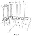
- FIG. 1 illustrates a low pressure turbine section of a gas turbine engine.
- the low pressure turbine section has individually bladed rotors that are stacked one at a time into the low pressure turbine case followed by a set of stators. The next rotor is placed onto the previous one and the two are bolted together. This sequence is repeated until all blades and vanes are installed.
- Separate turbine disks have been necessary to allow this style of assembly to work. The separate turbine disks add complexity and, therefore, cost and weight because of the flanges between the disks that must be machined, drilled and bolted together.
- there is a need for a turbine section that is less complex in structure and that has a reduced weight and cost associated with it.
- a turbine structure for use in a gas turbine engine is provided by the present invention.
- the turbine structure broadly comprises a one-piece drum rotor and a plurality of blades attached to the one-piece drum rotor.
- a method for installing a section of a turbine broadly comprises the steps of installing a one-piece drum rotor with an upstream set of turbine blades attached to the one-piece drum rotor.
- the installing step comprises joining the one-piece drum rotor to an adjacent structure.
- the turbine structure 10 for use in a gas turbine engine is illustrated.
- the turbine structure 10 has a one-piece drum rotor 12 where a plurality of axially spaced turbine disks 14 are welded together.
- the drum rotor 12 and the turbine disks 14 do not require additional machining, and bolts and nuts for joining them together. This results in a substantial reduction in weight and cost.
- the one-piece drum rotor 12 is preferably joined to another stage of the turbine section of a gas turbine engine via an integrally formed flange 18 and a plurality of attachment means 20, such as a plurality of circumferentially arranged nut and bolt arrangements, which pass through apertures 21 in the flange 18.
- the drum rotor 12 may be supported for rotation in any suitable manner known in the art.
- the drum rotor 12 at the leading disk 14 has a diameter greater than the diameter of the trailing disk 14.
- the disk diameter is reduced and additional clearance can be obtained. This allows axially spaced apart circumferential arrays of turbine blades 26 and 28 and axially spaced apart circumferential arrays of stator vanes 30 and 32 to be installed independently of the disks 14.
- the drum rotor 12 has a plurality of integrally formed, axially spaced apart disk attachments 34 located circumferentially around the drum rotor 12.
- Each of the disk attachments 34 may have any desired configuration known in the art.
- Arrays of turbine blades 26, 28, and 36 may be joined to the disk attachments 34 using any suitable mounting technique known in the art, such as the fir tree arrangement shown in the figures.
- the turbine structure 10 may be installed with an upstream array of turbine blades 36 already attached.
- the turbine structure 10 may be joined to the adjacent structure 35, which may have an array of turbine blades 70 and an array of stator vanes 72 attached thereto, by abutting flange 18 to a flange 74 and passing the attachment means 20 through an aperture 76 in the flange 74 and the aperture 21 in the flange 18.
- a circumferential array of stator vanes 30 may then be installed due to the extra clearance of the downstream disk attachment.
- the array of stator vanes 30 may include a knife seal arrangement 40.
- the seal arrangement 40 may include knife elements 42 integrally formed with the drum rotor 12.
- stator vanes 30 After the stator vanes 30 are installed, a second array of turbine blades 26 may then be installed. After the array of turbine blades 26 is installed, an assembly of stator vanes 32 may be installed, and after the stator vanes 32, a third array of turbine blades 28 may be installed.
- the turbine structure 10 may be the last three stages of a low pressure turbine section of a gas turbine engine.
- While the turbine structure 10 has been showing as having three stages, it may only two stages if desired. Such a configuration is shown in FIG. 5. Also, if desired, the turbine structure 10 may have more than three stages.
Landscapes
- Engineering & Computer Science (AREA)
- Mechanical Engineering (AREA)
- General Engineering & Computer Science (AREA)
- Turbine Rotor Nozzle Sealing (AREA)
Applications Claiming Priority (2)
| Application Number | Priority Date | Filing Date | Title |
|---|---|---|---|
| US10/720,875 US7128535B2 (en) | 2003-11-26 | 2003-11-26 | Turbine drum rotor for a turbine engine |
| US720875 | 2003-11-26 |
Publications (2)
| Publication Number | Publication Date |
|---|---|
| EP1536101A2 true EP1536101A2 (fr) | 2005-06-01 |
| EP1536101A3 EP1536101A3 (fr) | 2008-09-24 |
Family
ID=34465661
Family Applications (1)
| Application Number | Title | Priority Date | Filing Date |
|---|---|---|---|
| EP04257255A Withdrawn EP1536101A3 (fr) | 2003-11-26 | 2004-11-23 | Rotor à tambour pour une turbomachine et procédé d'installation |
Country Status (3)
| Country | Link |
|---|---|
| US (1) | US7128535B2 (fr) |
| EP (1) | EP1536101A3 (fr) |
| JP (1) | JP4081069B2 (fr) |
Cited By (2)
| Publication number | Priority date | Publication date | Assignee | Title |
|---|---|---|---|---|
| FR2971004A1 (fr) * | 2011-02-01 | 2012-08-03 | Snecma | Procede d'assemblage d'une turbine basse-pression de turboreacteur a double corps |
| EP2570608A3 (fr) * | 2011-05-26 | 2015-05-27 | United Technologies Corporation | Ensemble de rotor en composite à matrice céramique pour moteur à turbine à gaz, agencement de turbine et procédé d'assemblage associés |
Families Citing this family (6)
| Publication number | Priority date | Publication date | Assignee | Title |
|---|---|---|---|---|
| FR2870309B1 (fr) * | 2004-05-17 | 2006-07-07 | Snecma Moteurs Sa | Procede d'assemblage de disques aubages monoblocs et dispositif d'amortissement des vibrations des aubes de ces disques |
| FR2875534B1 (fr) † | 2004-09-21 | 2006-12-22 | Snecma Moteurs Sa | Module de turbine pour moteur a turbine a gaz avec rotor comportant un corps monobloc |
| US8167566B2 (en) * | 2008-12-31 | 2012-05-01 | General Electric Company | Rotor dovetail hook-to-hook fit |
| FR2940768B1 (fr) * | 2009-01-06 | 2013-07-05 | Snecma | Procede de fabrication d'un tambour de compresseur de turbomachine |
| EP3012411B1 (fr) * | 2014-10-23 | 2025-05-21 | RTX Corporation | Rotor à aubage intégral ayant un bras axial et une poche |
| ES2828719T3 (es) * | 2017-11-09 | 2021-05-27 | MTU Aero Engines AG | Disposición de sellado para una turbomáquina, método para la fabricación de una disposición de sellado y turbomáquina |
Citations (5)
| Publication number | Priority date | Publication date | Assignee | Title |
|---|---|---|---|---|
| US4483054A (en) | 1982-11-12 | 1984-11-20 | United Technologies Corporation | Method for making a drum rotor |
| US4743165A (en) | 1986-10-22 | 1988-05-10 | United Technologies Corporation | Drum rotors for gas turbine engines |
| US5156525A (en) | 1991-02-26 | 1992-10-20 | General Electric Company | Turbine assembly |
| US5350278A (en) | 1993-06-28 | 1994-09-27 | The United States Of America As Represented By The Secretary Of The Air Force | Joining means for rotor discs |
| EP0704601A1 (fr) | 1991-12-23 | 1996-04-03 | General Electric Company | Bouclier thermique combiné avec dispositif de retention pour boulon d'assemblage de turbine |
Family Cites Families (6)
| Publication number | Priority date | Publication date | Assignee | Title |
|---|---|---|---|---|
| NL66706C (fr) * | 1944-10-06 | |||
| GB612097A (en) * | 1946-10-09 | 1948-11-08 | English Electric Co Ltd | Improvements in and relating to the cooling of gas turbine rotors |
| GB1047281A (fr) * | 1964-01-23 | |||
| US3700353A (en) * | 1971-02-01 | 1972-10-24 | Westinghouse Electric Corp | Rotor structure and method of broaching the same |
| US3692429A (en) * | 1971-02-01 | 1972-09-19 | Westinghouse Electric Corp | Rotor structure and method of broaching the same |
| FR2607866B1 (fr) * | 1986-12-03 | 1991-04-12 | Snecma | Axes de fixation de rotors de turbomachine, procede de montage et rotors ainsi montes |
-
2003
- 2003-11-26 US US10/720,875 patent/US7128535B2/en not_active Expired - Lifetime
-
2004
- 2004-11-22 JP JP2004336876A patent/JP4081069B2/ja not_active Expired - Fee Related
- 2004-11-23 EP EP04257255A patent/EP1536101A3/fr not_active Withdrawn
Patent Citations (5)
| Publication number | Priority date | Publication date | Assignee | Title |
|---|---|---|---|---|
| US4483054A (en) | 1982-11-12 | 1984-11-20 | United Technologies Corporation | Method for making a drum rotor |
| US4743165A (en) | 1986-10-22 | 1988-05-10 | United Technologies Corporation | Drum rotors for gas turbine engines |
| US5156525A (en) | 1991-02-26 | 1992-10-20 | General Electric Company | Turbine assembly |
| EP0704601A1 (fr) | 1991-12-23 | 1996-04-03 | General Electric Company | Bouclier thermique combiné avec dispositif de retention pour boulon d'assemblage de turbine |
| US5350278A (en) | 1993-06-28 | 1994-09-27 | The United States Of America As Represented By The Secretary Of The Air Force | Joining means for rotor discs |
Cited By (2)
| Publication number | Priority date | Publication date | Assignee | Title |
|---|---|---|---|---|
| FR2971004A1 (fr) * | 2011-02-01 | 2012-08-03 | Snecma | Procede d'assemblage d'une turbine basse-pression de turboreacteur a double corps |
| EP2570608A3 (fr) * | 2011-05-26 | 2015-05-27 | United Technologies Corporation | Ensemble de rotor en composite à matrice céramique pour moteur à turbine à gaz, agencement de turbine et procédé d'assemblage associés |
Also Published As
| Publication number | Publication date |
|---|---|
| EP1536101A3 (fr) | 2008-09-24 |
| JP2005155625A (ja) | 2005-06-16 |
| JP4081069B2 (ja) | 2008-04-23 |
| US7128535B2 (en) | 2006-10-31 |
| US20050111970A1 (en) | 2005-05-26 |
Similar Documents
| Publication | Publication Date | Title |
|---|---|---|
| US20250116203A1 (en) | Turbomachine assembly comprising a half-shell casing bearing variable-pitch inlet stator vanes | |
| EP2620591B1 (fr) | Ensemble d'aube de stator de moteur à turbine à gaz avec virole interne | |
| US20040265124A1 (en) | Methods and apparatus for assembling gas turbine engines | |
| US20150047191A1 (en) | Method for balancing and assembling a turbine rotor | |
| EP3026212B1 (fr) | Dégagement de face de grille monobloc | |
| US20040179936A1 (en) | Tube-type vortex reducer with retaining ring | |
| US8162615B2 (en) | Split disk assembly for a gas turbine engine | |
| US20090317237A1 (en) | System and method for reduction of unsteady pressures in turbomachinery | |
| US10018061B2 (en) | Vane tip machining fixture assembly | |
| US7128535B2 (en) | Turbine drum rotor for a turbine engine | |
| US9951654B2 (en) | Stator blade sector for an axial turbomachine with a dual means of fixing | |
| EP2855898B1 (fr) | Bague tampon d'aube de stator | |
| EP2412940B1 (fr) | Montage de composant rotatif pour moteur à turbine à gaz | |
| US6881032B2 (en) | Exit stator mounting | |
| US5275532A (en) | Axial compressor and method of carrying out maintenance on the axial compressor | |
| US10724390B2 (en) | Collar support assembly for airfoils | |
| EP2644830B1 (fr) | Réduction de bruit dans une turbomachine et procédé associé | |
| US10612557B2 (en) | Nose cone attachment for turbofan engine | |
| KR20080018821A (ko) | 증기 터빈용 로터의 제조 방법 및 장치 | |
| US9045984B2 (en) | Stator vane mistake proofing | |
| US3338508A (en) | Axial-flow compressor | |
| US11215084B2 (en) | Support straps and method of assembly for gas turbine engine | |
| US20230203959A1 (en) | Bladed turbine stator for a turbine engine | |
| EP3613968A1 (fr) | Demoteur de turbine à gaz | |
| JPH08165903A (ja) | タービン静翼の固定構造 |
Legal Events
| Date | Code | Title | Description |
|---|---|---|---|
| PUAI | Public reference made under article 153(3) epc to a published international application that has entered the european phase |
Free format text: ORIGINAL CODE: 0009012 |
|
| AK | Designated contracting states |
Kind code of ref document: A2 Designated state(s): AT BE BG CH CY CZ DE DK EE ES FI FR GB GR HU IE IS IT LI LU MC NL PL PT RO SE SI SK TR |
|
| AX | Request for extension of the european patent |
Extension state: AL HR LT LV MK YU |
|
| PUAL | Search report despatched |
Free format text: ORIGINAL CODE: 0009013 |
|
| AK | Designated contracting states |
Kind code of ref document: A3 Designated state(s): AT BE BG CH CY CZ DE DK EE ES FI FR GB GR HU IE IS IT LI LU MC NL PL PT RO SE SI SK TR |
|
| AX | Request for extension of the european patent |
Extension state: AL HR LT LV MK YU |
|
| 17P | Request for examination filed |
Effective date: 20090220 |
|
| AKX | Designation fees paid |
Designated state(s): DE GB |
|
| 17Q | First examination report despatched |
Effective date: 20110422 |
|
| R17C | First examination report despatched (corrected) |
Effective date: 20110504 |
|
| STAA | Information on the status of an ep patent application or granted ep patent |
Free format text: STATUS: THE APPLICATION IS DEEMED TO BE WITHDRAWN |
|
| 18D | Application deemed to be withdrawn |
Effective date: 20140116 |