EP1536089A1 - Lock mechanism - Google Patents
Lock mechanism Download PDFInfo
- Publication number
- EP1536089A1 EP1536089A1 EP20040256032 EP04256032A EP1536089A1 EP 1536089 A1 EP1536089 A1 EP 1536089A1 EP 20040256032 EP20040256032 EP 20040256032 EP 04256032 A EP04256032 A EP 04256032A EP 1536089 A1 EP1536089 A1 EP 1536089A1
- Authority
- EP
- European Patent Office
- Prior art keywords
- lock
- lock lever
- lock mechanism
- abutment
- axis
- Prior art date
- Legal status (The legal status is an assumption and is not a legal conclusion. Google has not performed a legal analysis and makes no representation as to the accuracy of the status listed.)
- Withdrawn
Links
- 230000007246 mechanism Effects 0.000 title claims abstract description 92
- 230000005540 biological transmission Effects 0.000 claims abstract description 6
- 230000008878 coupling Effects 0.000 claims abstract description 3
- 238000010168 coupling process Methods 0.000 claims abstract description 3
- 238000005859 coupling reaction Methods 0.000 claims abstract description 3
- 230000006835 compression Effects 0.000 description 10
- 238000007906 compression Methods 0.000 description 10
- 230000000717 retained effect Effects 0.000 description 4
- 230000009471 action Effects 0.000 description 3
- 238000006243 chemical reaction Methods 0.000 description 3
- 230000001154 acute effect Effects 0.000 description 2
- 238000009877 rendering Methods 0.000 description 2
- 206010010904 Convulsion Diseases 0.000 description 1
- 230000004913 activation Effects 0.000 description 1
- 230000008859 change Effects 0.000 description 1
- 230000003993 interaction Effects 0.000 description 1
Images


Classifications
-
- E—FIXED CONSTRUCTIONS
- E05—LOCKS; KEYS; WINDOW OR DOOR FITTINGS; SAFES
- E05B—LOCKS; ACCESSORIES THEREFOR; HANDCUFFS
- E05B77/00—Vehicle locks characterised by special functions or purposes
- E05B77/22—Functions related to actuation of locks from the passenger compartment of the vehicle
- E05B77/24—Functions related to actuation of locks from the passenger compartment of the vehicle preventing use of an inner door handle, sill button, lock knob or the like
- E05B77/28—Functions related to actuation of locks from the passenger compartment of the vehicle preventing use of an inner door handle, sill button, lock knob or the like for anti-theft purposes, e.g. double-locking or super-locking
-
- E—FIXED CONSTRUCTIONS
- E05—LOCKS; KEYS; WINDOW OR DOOR FITTINGS; SAFES
- E05B—LOCKS; ACCESSORIES THEREFOR; HANDCUFFS
- E05B81/00—Power-actuated vehicle locks
- E05B81/12—Power-actuated vehicle locks characterised by the function or purpose of the powered actuators
- E05B81/16—Power-actuated vehicle locks characterised by the function or purpose of the powered actuators operating on locking elements for locking or unlocking action
-
- E—FIXED CONSTRUCTIONS
- E05—LOCKS; KEYS; WINDOW OR DOOR FITTINGS; SAFES
- E05B—LOCKS; ACCESSORIES THEREFOR; HANDCUFFS
- E05B81/00—Power-actuated vehicle locks
- E05B81/02—Power-actuated vehicle locks characterised by the type of actuators used
- E05B81/04—Electrical
- E05B81/06—Electrical using rotary motors
-
- E—FIXED CONSTRUCTIONS
- E05—LOCKS; KEYS; WINDOW OR DOOR FITTINGS; SAFES
- E05B—LOCKS; ACCESSORIES THEREFOR; HANDCUFFS
- E05B85/00—Details of vehicle locks not provided for in groups E05B77/00 - E05B83/00
- E05B85/08—Sill-buttons, garnish buttons or inner door lock knobs
-
- Y—GENERAL TAGGING OF NEW TECHNOLOGICAL DEVELOPMENTS; GENERAL TAGGING OF CROSS-SECTIONAL TECHNOLOGIES SPANNING OVER SEVERAL SECTIONS OF THE IPC; TECHNICAL SUBJECTS COVERED BY FORMER USPC CROSS-REFERENCE ART COLLECTIONS [XRACs] AND DIGESTS
- Y10—TECHNICAL SUBJECTS COVERED BY FORMER USPC
- Y10S—TECHNICAL SUBJECTS COVERED BY FORMER USPC CROSS-REFERENCE ART COLLECTIONS [XRACs] AND DIGESTS
- Y10S292/00—Closure fasteners
- Y10S292/23—Vehicle door latches
-
- Y—GENERAL TAGGING OF NEW TECHNOLOGICAL DEVELOPMENTS; GENERAL TAGGING OF CROSS-SECTIONAL TECHNOLOGIES SPANNING OVER SEVERAL SECTIONS OF THE IPC; TECHNICAL SUBJECTS COVERED BY FORMER USPC CROSS-REFERENCE ART COLLECTIONS [XRACs] AND DIGESTS
- Y10—TECHNICAL SUBJECTS COVERED BY FORMER USPC
- Y10T—TECHNICAL SUBJECTS COVERED BY FORMER US CLASSIFICATION
- Y10T292/00—Closure fasteners
- Y10T292/08—Bolts
- Y10T292/1043—Swinging
- Y10T292/1044—Multiple head
- Y10T292/1045—Operating means
- Y10T292/1047—Closure
-
- Y—GENERAL TAGGING OF NEW TECHNOLOGICAL DEVELOPMENTS; GENERAL TAGGING OF CROSS-SECTIONAL TECHNOLOGIES SPANNING OVER SEVERAL SECTIONS OF THE IPC; TECHNICAL SUBJECTS COVERED BY FORMER USPC CROSS-REFERENCE ART COLLECTIONS [XRACs] AND DIGESTS
- Y10—TECHNICAL SUBJECTS COVERED BY FORMER USPC
- Y10T—TECHNICAL SUBJECTS COVERED BY FORMER US CLASSIFICATION
- Y10T292/00—Closure fasteners
- Y10T292/08—Bolts
- Y10T292/1043—Swinging
- Y10T292/1075—Operating means
- Y10T292/1082—Motor
-
- Y—GENERAL TAGGING OF NEW TECHNOLOGICAL DEVELOPMENTS; GENERAL TAGGING OF CROSS-SECTIONAL TECHNOLOGIES SPANNING OVER SEVERAL SECTIONS OF THE IPC; TECHNICAL SUBJECTS COVERED BY FORMER USPC CROSS-REFERENCE ART COLLECTIONS [XRACs] AND DIGESTS
- Y10—TECHNICAL SUBJECTS COVERED BY FORMER USPC
- Y10T—TECHNICAL SUBJECTS COVERED BY FORMER US CLASSIFICATION
- Y10T70/00—Locks
- Y10T70/60—Systems
- Y10T70/625—Operation and control
- Y10T70/65—Central control
Definitions
- the present invention relates to lock mechanisms and in particular to lock mechanisms on vehicle doors.
- lockable latch mechanisms on vehicles which can be in an unlocked condition i.e. allowing opening of an associated door from the outside and from the inside, a locked condition where opening of the door from the outside is prevented but opening of the door from the inside is possible, and a superlocked condition wherein opening of the door from the inside or the outside is prevented.
- European patent application EP01303421 discloses a lock mechanism operable from the inside of a vehicle by a sill button or toggle switch.
- the sill button is connected to the lock mechanism via a coil bound helical spring. This spring acts in a non resilient manner when the sill button is subsequently operated to move the lock mechanism between the locked and unlocked conditions.
- the sill button is prevented from actuating the lock mechanism by the helical spring which then acts in a resilient manner when the sill button is operated in an attempt to move the lock mechanism from the superlocked condition.
- An object of the present invention is to provide an improved form of lock mechanism.
- a lock mechanism including a manually actuable element, a lock lever and an actuator, the manually actuable element being connected to the lock lever via a transmission path, the lock lever having locked, unlocked and superlocked positions relating to locked, unlocked and superlocked conditions of the lock mechanism, the lock lever being rotatable about an axis between locked, unlocked and superlocked positions by the actuator, the lock lever being rotatable about the axis between the locked and unlocked positions by operation of the manually actuable element, the transmission path including a rigid link having a first end in driven connection with the manually actuable element and a second end defining an abutment for selectively driving the lock lever via a drive feature, said drive feature coupling the abutment to the lock lever so that the abutment follows an arcuate path centred on the axis when the lock lever is rotated about the axis between locked and unlocked positions by operation of the manually actuable element, and said drive feature decoupling the abutment
- the resilient member is a helical spring preferably a helical compression spring, most preferably a helical compression spring.
- the resilient member is only required, in use, to act in a single direction.
- a lock mechanism 10 having a manually actuable element in the form of a sill button 12.
- the sill button 12 is mounted on a vehicle door panel 26. Downward movement of the sill button 12 is restricted by the sill button head 28 and upward movement is prevented by sill button stop 30.
- the sill button 12 is connected via a rigid link in the form of a connection rod 14 to a lock lever in the form of a lock gear 18.
- the lock gear 18 is rotationally mounted to chassis 11 at an axis 15 on pivot 16 and is driven by a stepper motor (not shown for clarity) via pinion gear 20. It will be appreciated that chassis 11 is not shown in figures 1B to 1D for clarity.
- the lock gear 18 defines a slot in the form of a slot, or channel 22.
- the elongate axis of the channel 22 is arranged upon the chord of a circle defined about axis 15.
- Located within the channel 22 is a pre-loaded compression spring 24, one end of which abuts an end face 22A of the channel 22.
- the other end of the spring 24 is in contact with an abutment 13 defined by the lower end of the connection rod 14.
- the abutment is retained within the channel 22 such that it may slide along the channel against the resistance of the spring 24.
- the spring 24 and the abutment 13 form a drive feature which maintains the lower end 14B of the connection rod 14 in driven contact with a second end 22B of the channel 22 during certain motor and manual operations of the lock mechanism, as will be explained further below.
- the sill button 12 has an unlocked position as shown in figure 1A, and a locked position as shown in figure 1B.
- the lock gear 18 has an unlocked position shown in figure 1A, a locked position as shown in figure 1B, and a superlocked position as shown in figures 1C and 1D.
- the lock gear 18 is connected to further components of a latch (not shown) to provide corresponding unlocked, locked and superlocked conditions of the latch.
- the sill button 12 and lock gear 18 are in their respective unlocked positions.
- the load applied to the connection rod 14 via the sill button 12 causes the abutment 13 to engage with a first wall 21 of the channel 22 at a position adjacent the second end 22B of the channel 22.
- the reaction between the abutment 13 and the first wall 21, under the action of the spring 24 generates sufficient friction to maintain a driven connection between the connection rod 14 and the lock lever 18, thus moving the lock lever from its unlocked to its locked position.
- lock mechanism can be either manually or electrically moved between the unlocked position shown in figure 1A and the locked position shown in figure 1B.
- the stepper motor via the pinion gear 20, drives the lock gear 18 from its locked position shown in figure 1B to its superlocked position shown in figure 1C.
- the abutment 13 has rotated over-centre with respect the axis 15 of the lock lever 18.
- the angle between the longitudinal axis of the connection rod 14 and the longitudinal axis of the channel 22 is small in this case 16° (show on figure 1C).
- the abutment 13 need not go over-centre with respect the pivot 16.
- the lock mechanism will operate satisfactorily as long as the angle between the connection rod 14 and the channel 22 is sufficiently acute that the spring 24 will compress upon actuation of the sill button 12 in an attempt to move the lock mechanism 10 from the superlocked position.
- connection rod 14 and the channel 22 must be sufficiently small such that a combination of the spring force and friction force generated by the reaction of the abutment 13 with the channel 22 is less than the force required to achieve a torque that will back drive the stepper motor. Where this condition is met the compression spring will compress when an attempt is made by the thief to move the lock gear 18 from the superlocked condition.
- the lock mechanism will remain in the superlocked and activated state shown in Figure 1D until such times as the sill button is released. Upon release the spring 24 will return the lock mechanism 10 to the superlocked condition of figure 1 C.
- Lock mechanism 110 has a connection rod 114 defining an abutment 113 at a lower end 114B thereof which acts in a notch 132 located at a second end 122B of a channel 122.
- the abutment also acts under the biasing force of a compression spring 124.
- the purpose of the notch 132 is to retain the abutment 113 in order that a direct drive link between a sill button 112 and the lock gear 118 is achieved when the lock mechanism 110 is moved between its unlocked position shown in figure 2A and its locked position shown in figure 2B.
- a sill button head 128 is arranged in relation to the door panel 126 such that the sill button 112 is prevented from being manually displaced from the unlocked position ( Figure 1A) by a sill button stop 130.
- the sill button head 128 is able to retreat below the exterior surface of the door panel 126 such that it cannot be accessed when the lock mechanism 110 is in the locked and superlocked positions ( Figures 2B and 2C, respectively).
- the lock mechanism 110 will act in a similar manner to the embodiment shown in figure 1, and 1D in particular.
- Figure 3 shows a lock mechanism 210 similar to that shown in figure 1, where the sill button is replaced with a two position toggle switch 34.
- the action of the lock mechanism when an attempt is made to move it from the superlocked position is similar to that shown in figure 1 and 1D in particular.
- FIGS 4A to 4E show a latch mechanism 40 similar to the lock mechanism 10 shown in figures 1A to 1D with the additional function of an inside lock override release.
- Inside lock override release operates to sequentially unlock a locked latch and then subsequently release the latch during a single pull of the release lever.
- release lever 42 has a released position shown in figure 4A, an unlocked position shown in figure 4B, and a locked position shown in figure 4C.
- the release lever 42 is connected to a release lock gear 44 by connection rod 14.
- Release lock gear 44 has a channel 22 in which is retained a compression spring 24 in a similar fashion to that shown in figure 1.
- the release lock gear 44 defines an arcuate slot 46 for receiving a pin 48.
- the pin 48 is mounted on a further lock gear 50.
- the further lock gear 50 is driven by a stepper motor (not shown for clarity) via pinion gear 20.
- a leaf spring 52 In contact with the outer profile of the release lock gear 44 is a leaf spring 52 having a head 54 biased towards the outer profile of the release lock gear 44.
- the outer profile of the release lock gear 44 defines a first detent position 56 and a second detent position 58.
- the outer profile further defines a flat 60 having a first abutment position 62 and a second abutment position 64. Both the first and second detent position 56, 58 and first and second abutment positions 62, 64 are provided for engagement with the head 54 of leaf spring 52.
- the release lock gear 44 has a released position (figure 4A) corresponding to the released position of the inside release lever 42, an unlocked position (figure 4B) corresponding to the unlocked position of the inside release lever 42, a locked position (figure 4C) corresponding to the locked position of the inside release lever 42, and a superlocked position (figure 4D).
- the further lock gear 50 has a non-superlock rest position 66 as shown in figures 4A, 4B and 4C, and a superlock position 68 as shown in figures 4D and 4E (note the position of lock gear pin 48 in the figures).
- the latch can be electrically locked by moving the pin 48 via the further lock gear 50 from its position shown in figure 4B to a position (shown dashed in figure 4C) where it is located at a first end 46A of the slot 46 thus driving the release lock gear 44 to the position shown in figure 4C.
- the pin is then returned to the non-superlock rest position 66 shown, in figure 4C thereby rendering the latch locked.
- the latch can be electrically unlocked by moving the pin 48 from the non-superlocked rest position 66 to a position (shown dashed in figure 4B) where it is arranged at a second end 46B of the slot 46 thus driving the release lock gear 44 to the position shown in figure 4B, before returning the pin to the non-superlock rest position 66.
- the stepper motor drives the further lock gear 50 via the pinion gear 20 in order to move the pin 48 from its non-superlock rest position 66 to drive against a first end 46A of the slot 46.
- This causes the rotation of the release lock gear 44 from its position shown in figure 4C to its position shown in figure 4D in which the inside release lever stop 43 abuts the chassis stop 72 (only shown in figure 4D for clarity).
- the abutment 13 has been moved over-centre of pivot 16 and as a result the angle between the elongate axis of the connection rod 14 and the elongate axis of the channel 22 is small.
- the stepper motor drives the further lock gear 50 via the pinion gear 20 in order to move the pin 48 from its superlocked position to drive against a second end 46B of the slot 46. This causes the rotation of the release lock gear from its position shown in figure 4D to its position shown in figure 4C thereby putting the latch into a locked (but not superlocked) state.
- the latch mechanism is electrically operated directly from the unlocked position (4B) to the superlocked position (4D), and likewise from the superlocked position (4D) to the unlocked position (4B).
- the latch mechanism 140 has a notch 132 arranged at a second end 122B of a channel 122 and further does not include a spring.
- the geometry of the notch 132 is such that a spring is not required to provide a biasing force against the abutment in order to provide a constant drive connection between the connection rod 114 and the release lock gear 44 when the latch is moved between the released, unlocked, and locked positions.
- FIG 6 there is provided a latch mechanism 240 similar to that shown in figure 5.
- the latch mechanism 240 has a coil spring 74 mounted on a chassis 211 of the latch on a coil spring pin 84 and reacted by coil spring stop 82.
- the spring 74 acts in combination with a notch 232 similar to that illustrated in figures 5A to 5E.
- the coil spring 74 provides resilience against movement of the release lever 242 when an attempt is made to move the release lever 242 from the superlocked position to the released position.
- Coil spring 74 is doing same job as the door panel spring 70 of the embodiment shown in figures 4A to 4E.
- the operation of the latch mechanism is otherwise similar to that shown in figures 4A to 4E.
- a lock mechanism 210 has a tension spring 76 in place of the compression spring 24 of the embodiment of figures 1A to 1D.
- the spring 76 is mounted on a mount 76 which is retained by a lug 80 of the lock gear 216.
- This embodiment operates in the same manner as that described for the embodiment of figures 1A to 1D. It will be appreciated that the end of spring could be fixed to chassis 211 instead of the lug 80 in an alternative embodiment.
- notch 32, 132, 232, coil spring 70 or tension spring 74 are applicable to any of the lock mechanisms or latch mechanisms described previously.
Landscapes
- Lock And Its Accessories (AREA)
Abstract
the manually actuable element (12) being connected to the lock lever (18) via a transmission path,
the lock lever (18) having locked, unlocked and superlocked positions relating to locked, unlocked and superlocked conditions of the lock mechanism (10),
the lock lever (18) being rotatable about an axis of rotation (15) between locked, unlocked and superlocked positions by the actuator,
the lock lever (18) being rotatable about the axis of rotation (15) between the locked and unlocked positions by operation of the manually actuable element (12),
the transmission path including a rigid link (14) having a first end in driven connection with the manually actuable element (12) and a second end defining an abutment (13) for selectively driving the lock lever (18) via a drive feature,
said drive feature coupling the abutment (13) to the lock lever (18) so that the abutment (13) follows an arcuate path centred on the axis of rotation (15) when the lock lever (18) is rotated about the axis (15) between locked and unlocked positions by operation of the manually actuable element (12),
and said drive feature decoupling the abutment (13) from the lock lever (18) when the manually actuable element (12) is actuated in an attempt to move the lock lever (18) from the superlocked position, so that the abutment (13) moves relative to the lock lever (18).
Description
- The present invention relates to lock mechanisms and in particular to lock mechanisms on vehicle doors.
- It is known to provide lockable latch mechanisms on vehicles which can be in an unlocked condition i.e. allowing opening of an associated door from the outside and from the inside, a locked condition where opening of the door from the outside is prevented but opening of the door from the inside is possible, and a superlocked condition wherein opening of the door from the inside or the outside is prevented.
- European patent application EP01303421 discloses a lock mechanism operable from the inside of a vehicle by a sill button or toggle switch. The sill button is connected to the lock mechanism via a coil bound helical spring. This spring acts in a non resilient manner when the sill button is subsequently operated to move the lock mechanism between the locked and unlocked conditions. When the lock mechanism is electrically driven to the superlocked condition, the sill button is prevented from actuating the lock mechanism by the helical spring which then acts in a resilient manner when the sill button is operated in an attempt to move the lock mechanism from the superlocked condition.
- However, in the event of the vehicle being involved in a collision there may be sufficient damage to the lock mechanism to cause the lock mechanism to partially seize. If the latch were locked at the time of the collision, exit from the vehicle may be impeded since the helical spring may elastically deform rather than transmitting sufficient force to the lock mechanism to change the latch status to unlocked. In such circumstances it would not be possible to unlock the door from the inside of the vehicle.
- An object of the present invention is to provide an improved form of lock mechanism.
- Thus, according to the present invention there is provided a lock mechanism including a manually actuable element, a lock lever and an actuator,
the manually actuable element being connected to the lock lever via a transmission path,
the lock lever having locked, unlocked and superlocked positions relating to locked, unlocked and superlocked conditions of the lock mechanism,
the lock lever being rotatable about an axis between locked, unlocked and superlocked positions by the actuator,
the lock lever being rotatable about the axis between the locked and unlocked positions by operation of the manually actuable element,
the transmission path including a rigid link having a first end in driven connection with the manually actuable element and a second end defining an abutment for selectively driving the lock lever via a drive feature,
said drive feature coupling the abutment to the lock lever so that the abutment follows an arcuate path centred on the axis when the lock lever is rotated about the axis between locked and unlocked positions by operation of the manually actuable element,
and said drive feature decoupling the abutment from the lock lever when the manually actuable element is actuated in an attempt to move the lock lever from the superlocked position, so that the abutment moves relative to the lock lever. - Preferably, the resilient member is a helical spring preferably a helical compression spring, most preferably a helical compression spring.
- Preferably, the resilient member is only required, in use, to act in a single direction.
- The invention will now be described by way of example only with reference to the accompanying drawings in which:
- Figures 1A to 1D are schematic views of a first embodiment of a lock mechanism in accordance with the present invention,
- Figures 2A to 2C are schematic views of a second embodiment of the lock mechanism according to the present invention,
- Figure 3 is a schematic view of a third embodiment of the lock mechanism in accordance with the present invention,
- Figures 4A to 4E are schematic views of a first embodiment of a latch mechanism in accordance with the present invention,
- Figures 5A to 5E are schematic views of a second embodiment of a latch mechanism according to the present invention,
- Figure 6 is a schematic view of a third embodiment of a latch mechanism in accordance with the present invention.
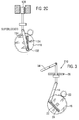
- Figure 7 is a schematic view of a fourth embodiment of a latch mechanism in accordance with the present invention.
-
- With reference to figures 1A to 1D there is shown a
lock mechanism 10 having a manually actuable element in the form of asill button 12. Thesill button 12 is mounted on avehicle door panel 26. Downward movement of thesill button 12 is restricted by thesill button head 28 and upward movement is prevented bysill button stop 30. Thesill button 12 is connected via a rigid link in the form of aconnection rod 14 to a lock lever in the form of alock gear 18. Thelock gear 18 is rotationally mounted tochassis 11 at anaxis 15 onpivot 16 and is driven by a stepper motor (not shown for clarity) viapinion gear 20. It will be appreciated thatchassis 11 is not shown in figures 1B to 1D for clarity. - The
lock gear 18 defines a slot in the form of a slot, orchannel 22. The elongate axis of thechannel 22 is arranged upon the chord of a circle defined aboutaxis 15. Located within thechannel 22 is apre-loaded compression spring 24, one end of which abuts anend face 22A of thechannel 22. The other end of thespring 24 is in contact with anabutment 13 defined by the lower end of theconnection rod 14. The abutment is retained within thechannel 22 such that it may slide along the channel against the resistance of thespring 24. - The
spring 24 and theabutment 13 form a drive feature which maintains thelower end 14B of theconnection rod 14 in driven contact with asecond end 22B of thechannel 22 during certain motor and manual operations of the lock mechanism, as will be explained further below. - The
sill button 12 has an unlocked position as shown in figure 1A, and a locked position as shown in figure 1B. Thelock gear 18 has an unlocked position shown in figure 1A, a locked position as shown in figure 1B, and a superlocked position as shown in figures 1C and 1D. - The
lock gear 18 is connected to further components of a latch (not shown) to provide corresponding unlocked, locked and superlocked conditions of the latch. - With the
lock mechanism 10 positioned as shown in figure 1A, thesill button 12 andlock gear 18 are in their respective unlocked positions. When thesill button 12 is manually moved from the unlocked position shown in figure 1A to the locked position shown in figure 1B the load applied to theconnection rod 14 via thesill button 12 causes theabutment 13 to engage with afirst wall 21 of thechannel 22 at a position adjacent thesecond end 22B of thechannel 22. The reaction between theabutment 13 and thefirst wall 21, under the action of thespring 24 generates sufficient friction to maintain a driven connection between theconnection rod 14 and thelock lever 18, thus moving the lock lever from its unlocked to its locked position. Whilst spring acts on theabutment 13 throughout the rotation of thelock gear 18 from the unlocked to the locked position, its main purpose during manual unlocking is to provide a reaction againstabutment 13 until the angle between thechannel 22 and theconnection rod 14 reaches 90°. After this point the spring force becomes redundant. After this point theabutment 13 acts directly on thesecond end 22B and thefirst wall 21. However see below for operation during electrical locking. - It will be appreciated that initial movement of the
sill button 12 andlock gear 18 will do little work since the slack in the system will need to be taken up. Thus, the angle between thechannel 22 and theconnection rod 14 will have started to approach 90° before any significant torque is applied to the gear wheel. Movement of thelock lever 18 will be achieved upon a sufficient force being generated between theabutment 13 and thelock lever 18. - When the
pinion gear 20 is driven by the stepper motor upon electric locking of the door, thelock gear 18 is driven to the locked position as shown in figure 1B. During this operation the load applied to theabutment 13 by thespring 24 is redundant until thechannel 22 has been rotated past a position where it is at 90° degrees to theconnection rod 14. After this point theabutment 13 acts in conjunction with thewall 23 and thespring 24 in a similar way to that described above, under manual locking of the lock mechanism. - When the
lock lever 18 is moved from the locked position of figure 1B to the unlocked position of figure 1A by manual actuation of thesill button 12, theabutment 13 is retained by thespring 24 andsecond wall 23 of thechannel 22 until the angle between the connection rod of thesill button 12, and thechannel 22 is greater than 90° degrees. When the lock mechanism is electrically driven between locked and unlocked positions the load applied by thespring 24 on theabutment 13 is redundant until thelock lever 18 has rotated past the point where the angle between theconnection rod 14 andchannel 22 is 90° degrees. - In the manner described above the lock mechanism can be either manually or electrically moved between the unlocked position shown in figure 1A and the locked position shown in figure 1B.
- To superlock the door, the stepper motor, via the
pinion gear 20, drives thelock gear 18 from its locked position shown in figure 1B to its superlocked position shown in figure 1C. It will be noted that in its superlocked position theabutment 13 has rotated over-centre with respect theaxis 15 of thelock lever 18. In the superlocked position the angle between the longitudinal axis of theconnection rod 14 and the longitudinal axis of thechannel 22 is small in thiscase 16° (show on figure 1C). As a result, when thesill button 12 is actuated (for example by a thief attempting to gain entry to the associated vehicle) in an attempt to move the latch mechanism from the superlocked position, thespring 24 compresses as shown in figure 1D and the lock remains in the super lock condition. - It will be appreciated that the
abutment 13 need not go over-centre with respect thepivot 16. The lock mechanism will operate satisfactorily as long as the angle between theconnection rod 14 and thechannel 22 is sufficiently acute that thespring 24 will compress upon actuation of thesill button 12 in an attempt to move thelock mechanism 10 from the superlocked position. - In other words, the angle between the
connection rod 14 and thechannel 22 must be sufficiently small such that a combination of the spring force and friction force generated by the reaction of theabutment 13 with thechannel 22 is less than the force required to achieve a torque that will back drive the stepper motor. Where this condition is met the compression spring will compress when an attempt is made by the thief to move thelock gear 18 from the superlocked condition. - The lock mechanism will remain in the superlocked and activated state shown in Figure 1D until such times as the sill button is released. Upon release the
spring 24 will return thelock mechanism 10 to the superlocked condition of figure 1 C. - As a result of this arrangement, manual operation of the mechanism via the
sill button 12 between unlocked and locked statuses is achieved with theconnection rod 14 in constant driven contact with thelock gear 18. Consequently, where the lock mechanism suffers a partial seizure following, for example, an impact from a second vehicle, the occupants are able to unlock the lock mechanism since there is a direct drive between theabutment 13 and thelock lever 18 when thelock gear 18 is moved from its lock position (figure 1B) to its unlocked position (figure 1A). - It will be appreciated that the spring only ever acts in a single direction, namely in compression. At no point during normal operation of the lock mechanism required to act in tension.
- With reference now to figure 2, in which components which perform substantially the same function as those of figure 1 are labelled 100 greater than those in figure 1 and the principle of operation of the lock mechanism being the same.
Lock mechanism 110 has aconnection rod 114 defining anabutment 113 at alower end 114B thereof which acts in anotch 132 located at asecond end 122B of achannel 122. The abutment also acts under the biasing force of acompression spring 124. The purpose of thenotch 132 is to retain theabutment 113 in order that a direct drive link between asill button 112 and thelock gear 118 is achieved when thelock mechanism 110 is moved between its unlocked position shown in figure 2A and its locked position shown in figure 2B. - Furthermore a
sill button head 128 is arranged in relation to thedoor panel 126 such that thesill button 112 is prevented from being manually displaced from the unlocked position (Figure 1A) by asill button stop 130. However, thesill button head 128 is able to retreat below the exterior surface of thedoor panel 126 such that it cannot be accessed when thelock mechanism 110 is in the locked and superlocked positions (Figures 2B and 2C, respectively). In the unlikely event that thesill button head 128 is manually accessed when thelock mechanism 110 is in the superlocked condition and an attempt is made to move the latch from its superlocked condition, thelock mechanism 110 will act in a similar manner to the embodiment shown in figure 1, and 1D in particular. It will be clear that upon attempting to move the lock mechanism manually from its superlocked position theabutment 113 does not engage thenotch 132 by virtue of the angle between theconnection rod 114 and thechannel 122. The activation of thesill button 112 when the lock mechanism is in the superlocked position moves theabutment 113 away from thenotch 132. - Figure 3 shows a
lock mechanism 210 similar to that shown in figure 1, where the sill button is replaced with a twoposition toggle switch 34. The action of the lock mechanism when an attempt is made to move it from the superlocked position is similar to that shown in figure 1 and 1D in particular. - Figures 4A to 4E show a
latch mechanism 40 similar to thelock mechanism 10 shown in figures 1A to 1D with the additional function of an inside lock override release. Inside lock override release operates to sequentially unlock a locked latch and then subsequently release the latch during a single pull of the release lever. - Inside
release lever 42 has a released position shown in figure 4A, an unlocked position shown in figure 4B, and a locked position shown in figure 4C. Therelease lever 42 is connected to arelease lock gear 44 byconnection rod 14.Release lock gear 44 has achannel 22 in which is retained acompression spring 24 in a similar fashion to that shown in figure 1. Therelease lock gear 44 defines anarcuate slot 46 for receiving apin 48. Thepin 48 is mounted on afurther lock gear 50. Thefurther lock gear 50 is driven by a stepper motor (not shown for clarity) viapinion gear 20. In contact with the outer profile of therelease lock gear 44 is aleaf spring 52 having ahead 54 biased towards the outer profile of therelease lock gear 44. The outer profile of therelease lock gear 44 defines afirst detent position 56 and asecond detent position 58. The outer profile further defines a flat 60 having afirst abutment position 62 and asecond abutment position 64. Both the first andsecond detent position head 54 ofleaf spring 52. Therelease lock gear 44 has a released position (figure 4A) corresponding to the released position of theinside release lever 42, an unlocked position (figure 4B) corresponding to the unlocked position of theinside release lever 42, a locked position (figure 4C) corresponding to the locked position of theinside release lever 42, and a superlocked position (figure 4D). Thefurther lock gear 50 has anon-superlock rest position 66 as shown in figures 4A, 4B and 4C, and asuperlock position 68 as shown in figures 4D and 4E (note the position oflock gear pin 48 in the figures). - The operation of the latch mechanism is as follows:-
- Figure 4A to 4E shows the latch in its released position, having been manually activated by
a vehicle occupant. Further clockwise rotation of the
release lock gear 44 is prevented by the provision of an insiderelease lever stop 43 abutting thedoor panel 26. The latch arrangement is provided with adoor panel spring 70 which acts to return therelease lever 42 from the release position as shown in figure 4A to the unlocked position shown in figure 4B when the vehicle occupant lets go of the lever. Thus, under the action of thedoor panel spring 70, therelease lock gear 44 is caused to rotate to its unlocked position as shown in figure 4B, in which theleaf spring 52 is located at thesecond abutment position 64 of flat 60 and thus acts as a detent. It will be noted that thepin 48 has not been caused to move. -
- With reference now to figure 4C, manual actuation of the
inside release lever 42 in order to lock the mechanism causes rotation of therelease lock gear 44 such that thehead 54 of theleaf spring 52 locates at the first detent position. - It will be appreciated that it is equally possible to repeat the above steps in reverse order to that detailed above, moving from the locked position shown in figure 4C to the unlocked position shown in figure 4B. A continued actuation of the release lever will release the door by moving the
inside release lever 42 to the position shown in figure 4A. - Starting at the position shown in figure 4B the latch can be electrically locked by moving the
pin 48 via thefurther lock gear 50 from its position shown in figure 4B to a position (shown dashed in figure 4C) where it is located at afirst end 46A of theslot 46 thus driving therelease lock gear 44 to the position shown in figure 4C. The pin is then returned to thenon-superlock rest position 66 shown, in figure 4C thereby rendering the latch locked. Starting at the position shown in figure 4C the latch can be electrically unlocked by moving thepin 48 from thenon-superlocked rest position 66 to a position (shown dashed in figure 4B) where it is arranged at asecond end 46B of theslot 46 thus driving therelease lock gear 44 to the position shown in figure 4B, before returning the pin to thenon-superlock rest position 66. - To superlock the latch mechanism, the stepper motor drives the
further lock gear 50 via thepinion gear 20 in order to move thepin 48 from itsnon-superlock rest position 66 to drive against afirst end 46A of theslot 46. This causes the rotation of therelease lock gear 44 from its position shown in figure 4C to its position shown in figure 4D in which the insiderelease lever stop 43 abuts the chassis stop 72 (only shown in figure 4D for clarity). In this position theabutment 13 has been moved over-centre ofpivot 16 and as a result the angle between the elongate axis of theconnection rod 14 and the elongate axis of thechannel 22 is small. - As with the lock mechanism embodiment of figures 1A-1D, it is conceivable that the abutment does not go over-centre as long as angle between the
connection rod 14 and thechannel 122 is sufficiently acute that thespring 24 will compress upon actuation of theinside release lever 42 in an attempt to move thelatch mechanism 40 from the superlocked position. - Consequently, when the
inside release lever 42 is moved in an attempt to move the latch from the superlocked position shown in figure 4D, thespring 24 is compressed as shown in figure 4E. As a result there is no movement of therelease lock gear 44, rendering ineffectual the movement of therelease lever 42 when the latch mechanism is in its superlocked position. - To unsuperlock the latch mechanism the stepper motor drives the
further lock gear 50 via thepinion gear 20 in order to move thepin 48 from its superlocked position to drive against asecond end 46B of theslot 46. This causes the rotation of the release lock gear from its position shown in figure 4D to its position shown in figure 4C thereby putting the latch into a locked (but not superlocked) state. - The interaction of the
abutment 13, thespring 24 and thechannel 22 during the operation of the latch between released, locked and unlocked is similar to that exhibited by the lock mechanism embodiment of figure 1. - Of course, it is possible for the latch mechanism to be electrically operated directly from the unlocked position (4B) to the superlocked position (4D), and likewise from the superlocked position (4D) to the unlocked position (4B).
- In figures 5A to 5E the
latch mechanism 140 has anotch 132 arranged at asecond end 122B of achannel 122 and further does not include a spring. The geometry of thenotch 132 is such that a spring is not required to provide a biasing force against the abutment in order to provide a constant drive connection between theconnection rod 114 and therelease lock gear 44 when the latch is moved between the released, unlocked, and locked positions. - It will be noted that in use the compression spring of each of the lock and latch mechanisms above is only required to act in one direction, i.e. in compression.
- In figure 6 there is provided a
latch mechanism 240 similar to that shown in figure 5. Thelatch mechanism 240 has a coil spring 74 mounted on achassis 211 of the latch on acoil spring pin 84 and reacted by coil spring stop 82. The spring 74 acts in combination with anotch 232 similar to that illustrated in figures 5A to 5E. The coil spring 74 provides resilience against movement of the release lever 242 when an attempt is made to move the release lever 242 from the superlocked position to the released position. Coil spring 74 is doing same job as thedoor panel spring 70 of the embodiment shown in figures 4A to 4E. The operation of the latch mechanism is otherwise similar to that shown in figures 4A to 4E. - In figure 7 a
lock mechanism 210 has atension spring 76 in place of thecompression spring 24 of the embodiment of figures 1A to 1D. Thespring 76 is mounted on amount 76 which is retained by alug 80 of thelock gear 216. This embodiment operates in the same manner as that described for the embodiment of figures 1A to 1D. It will be appreciated that the end of spring could be fixed tochassis 211 instead of thelug 80 in an alternative embodiment. - It is conceivable within the scope of the invention that the
notch coil spring 70 or tension spring 74 are applicable to any of the lock mechanisms or latch mechanisms described previously. - It is also conceivable within the scope of the invention that a DC motor and solenoid arrangement of known type be used in place of the stepper motor in any of the lock or latch arrangements described herein.
Claims (16)
- A lock mechanism (10) including a manually actuable element (12), a lock lever (18) and an actuator,
the manually actuable element (12) being connected to the lock lever (18) via a transmission path,
the lock lever (18) having locked, unlocked and superlocked positions relating to locked, unlocked and superlocked conditions of the lock mechanism (10),
the lock lever (18) being rotatable about an axis of rotation (15) between locked, unlocked and superlocked positions by the actuator,
the lock lever (18) being rotatable about the axis of rotation (15) between the locked and unlocked positions by operation of the manually actuable element (12),
the transmission path including a rigid link (14) having a first end in driven connection with the manually actuable element (12) and a second end defining an abutment (13) for selectively driving the lock lever (18) via a drive feature,
said drive feature coupling the abutment (13) to the lock lever (18) so that the abutment (13) follows an arcuate path centred on the axis of rotation (15) when the lock lever (18) is rotated about the axis of rotation (15) between locked and unlocked positions by operation of the manually actuable element (12),
and said drive feature decoupling the abutment (13) from the lock lever (18) when the manually actuable element (12) is actuated in an attempt to move the lock lever (18) from the superlocked position, so that the abutment (13) moves relative to the lock lever (18). - A lock mechanism (10) as defined in claim 1 wherein the drive feature includes an elongate slot (22) in the lock gear (18).
- A lock mechanism as defined in claim 2 wherein the drive feature includes a notch (132) arranged at a first end of the elongate slot for engaging the abutment.
- A lock mechanism according to claim 2 or 3 wherein the drive feature includes a resilient member (24).
- A lock mechanism according to claim 4 wherein the resilient member is located within the elongate slot.
- A lock mechanism (10) according to claims 4 or 5 wherein a first end of the resilient member (24) abuts the abutment (13), the second end of the resilient member (24) abutting a second end of the elongate slot (22).
- A lock mechanism according to any one of claims 2 to 6 wherein an elongate axis of the elongate slot (22) is located upon a chord of said axis of rotation (15).
- A lock mechanism according to any one of claims 2 to 7 wherein the axis of rotation (15) is arranged between a longitudinal mid-point of the elongate slot (22) and a first end of the rigid link (14).
- A lock mechanism according to any preceding claim wherein a line between the first and second end of the rigid link (14) is arranged substantially to a first side of the axis of rotation (15) when the lock mechanism (10) is in the unlocked or locked condition, the line being arranged substantially to a second side of the axis of rotation (15) when the lock mechanism (10) is in the superlocked condition such that the second end of the rigid link (14) has moved over centre with respect the axis of rotation (15) of the lock lever.
- A lock mechanism according to any one of claims 2 to 9 wherein a longitudinal centreline of the elongate slot (22) and the line between the first and second ends of the rigid link (14) forms an angle of 0 ± 20 degrees when the lock mechanism is in the superlocked position.
- A lock mechanism according to any preceding claim wherein the manually actuable element is a sill button.
- A lock mechanism according to any one of claims 1 to 10 in which the manually actuable element is a two position toggle.
- A latch mechanism including the lock mechanism according to any one of claims 1 to 10 wherein
the lock lever (18) has a released position corresponding to a released condition of the latch mechanism,
the lock lever (18) being moveable between released, locked and unlocked positions by operation of the manually actuable element (12). - A latch mechanism according to claim 13 wherein the lock gear (18) is rotatably mounted on a chassis (11), the drive feature includes a coil spring (20) having a long arm at one end of the spring and a short arm at the other end of the spring (20), the short end being mounted in fixed relation to the axis of rotation (15), the long arm being in communication with the abutment (13) such that the coil spring (20) biases the rigid link (14) in a direction away from the manually actuable element (12).
- A latch mechanism according to claim 14 wherein an arm of the coil spring (20) is mounted on the chassis (11).
- A latch mechanism according to any one of claims 13 to 15 wherein the manually actuable element is an inside release lever.
Applications Claiming Priority (2)
| Application Number | Priority Date | Filing Date | Title |
|---|---|---|---|
| GB0323268 | 2003-10-04 | ||
| GB0323268A GB0323268D0 (en) | 2003-10-04 | 2003-10-04 | Lock mechanism |
Publications (1)
| Publication Number | Publication Date |
|---|---|
| EP1536089A1 true EP1536089A1 (en) | 2005-06-01 |
Family
ID=29415522
Family Applications (1)
| Application Number | Title | Priority Date | Filing Date |
|---|---|---|---|
| EP20040256032 Withdrawn EP1536089A1 (en) | 2003-10-04 | 2004-09-30 | Lock mechanism |
Country Status (3)
| Country | Link |
|---|---|
| US (1) | US7070214B2 (en) |
| EP (1) | EP1536089A1 (en) |
| GB (1) | GB0323268D0 (en) |
Families Citing this family (5)
| Publication number | Priority date | Publication date | Assignee | Title |
|---|---|---|---|---|
| JP4875417B2 (en) * | 2006-06-28 | 2012-02-15 | 株式会社ホンダロック | Vehicle door opening and closing device |
| US8069616B2 (en) * | 2007-09-07 | 2011-12-06 | Brose Schliesssysteme Gmbh & Co. Kg | Method for mounting a motor vehicle door lock |
| US9085918B2 (en) * | 2013-04-09 | 2015-07-21 | GM Global Technology Operations LLC | Status indicator system for a vehicle door lock |
| US20160138301A1 (en) * | 2014-11-14 | 2016-05-19 | The Boeing Company | Self-contained electronic stowage bin system |
| DE102019133324A1 (en) * | 2019-12-06 | 2021-06-10 | Kiekert Aktiengesellschaft | Motor vehicle lock, in particular motor vehicle door lock |
Citations (4)
| Publication number | Priority date | Publication date | Assignee | Title |
|---|---|---|---|---|
| US5722272A (en) * | 1994-01-11 | 1998-03-03 | Rockwell Light Vehicle Systems (Uk) Limited | Vehicle door lock actuator |
| EP0829602A1 (en) * | 1996-09-11 | 1998-03-18 | ROLTRA MORSE S.p.A. | Vehicle door lock assembly |
| EP1149967A2 (en) * | 2000-04-25 | 2001-10-31 | Meritor Light Vehicle Systems (UK) Ltd | A lock mechanism |
| EP1213423A2 (en) * | 2000-11-29 | 2002-06-12 | Meritor Light Vehicle Systems (UK) Ltd | Lock arrangement |
Family Cites Families (8)
| Publication number | Priority date | Publication date | Assignee | Title |
|---|---|---|---|---|
| IT1131405B (en) * | 1979-03-24 | 1986-06-25 | Kiekert Soehne Arn | CENTRALIZED CLOSING DEVICE FOR MOTOR VEHICLE DOORS |
| US4433355A (en) * | 1980-03-04 | 1984-02-21 | Yale Security Products Ltd. | Electronic locks for doors |
| GB2207698B (en) * | 1987-08-07 | 1990-11-28 | Rockwell Automotive Body Co | Vehicle door latches and locking mechanism |
| JPH0828119A (en) * | 1994-05-13 | 1996-01-30 | Nippondenso Co Ltd | Door lock driving device |
| DE19600524B4 (en) * | 1995-12-20 | 2006-07-06 | Siemens Ag | Lock, in particular for motor vehicle doors |
| FR2785638B1 (en) * | 1998-11-09 | 2000-12-29 | Valeo Securite Habitacle | DOOR LOCK WITH EXTERNAL AND / OR INTERIOR ELECTRICAL LOCKING / UNLOCKING FOR MOTOR VEHICLE |
| GB0119415D0 (en) * | 2001-08-09 | 2001-10-03 | Meritor Light Vehicle Sys Ltd | A lock link mechanism |
| EP1347131A1 (en) * | 2002-03-19 | 2003-09-24 | Ford Global Technologies, Inc. | Door handle device |
-
2003
- 2003-10-04 GB GB0323268A patent/GB0323268D0/en not_active Ceased
-
2004
- 2004-09-30 EP EP20040256032 patent/EP1536089A1/en not_active Withdrawn
- 2004-10-04 US US10/958,180 patent/US7070214B2/en not_active Expired - Fee Related
Patent Citations (4)
| Publication number | Priority date | Publication date | Assignee | Title |
|---|---|---|---|---|
| US5722272A (en) * | 1994-01-11 | 1998-03-03 | Rockwell Light Vehicle Systems (Uk) Limited | Vehicle door lock actuator |
| EP0829602A1 (en) * | 1996-09-11 | 1998-03-18 | ROLTRA MORSE S.p.A. | Vehicle door lock assembly |
| EP1149967A2 (en) * | 2000-04-25 | 2001-10-31 | Meritor Light Vehicle Systems (UK) Ltd | A lock mechanism |
| EP1213423A2 (en) * | 2000-11-29 | 2002-06-12 | Meritor Light Vehicle Systems (UK) Ltd | Lock arrangement |
Also Published As
| Publication number | Publication date |
|---|---|
| GB0323268D0 (en) | 2003-11-05 |
| US20050077733A1 (en) | 2005-04-14 |
| US7070214B2 (en) | 2006-07-04 |
Similar Documents
| Publication | Publication Date | Title |
|---|---|---|
| US7543861B2 (en) | Lock for an opening on a motor vehicle, with a memory for unlocking locking | |
| CN102165130B (en) | Motor vehicle door lock | |
| US10683682B2 (en) | Closure latch for vehicle door having double pull release mechanism driven by child lock actuator | |
| US8267444B2 (en) | Door lock apparatus for vehicle | |
| KR101217432B1 (en) | global Side Door Latch | |
| US7399010B2 (en) | Power-actuated motor-vehicle door latch with quick unlock | |
| CN1550629B (en) | A lock mechanism | |
| US20020093207A1 (en) | Door lock having a closing aid | |
| JPH0296079A (en) | Door closing appliance | |
| CN110397357A (en) | Remote double lock assembly for use with closed latch assemblies in vehicle doors | |
| EP1580365A1 (en) | Latch mechanism | |
| EP1536089A1 (en) | Lock mechanism | |
| JP2025522044A (en) | Automobile locks, particularly automobile door locks | |
| JP2024537364A (en) | Automobile locks, particularly automobile door locks | |
| EP1149967B1 (en) | A lock mechanism | |
| US6866310B2 (en) | Door latch operation device for vehicle | |
| CN222314885U (en) | Vehicle latch | |
| CN117027567B (en) | Car door locks and vehicle | |
| CN117988634A (en) | Door latch | |
| WO2003071064A1 (en) | Latch having releasable cinching mechanism | |
| EP1179109A1 (en) | Lock for a vehicle door | |
| CN223922833U (en) | Emergency release and suction interrupt mechanism for automobile tail door lock | |
| GB2306552A (en) | Vehicle door lock superlocking actuator | |
| CN218029543U (en) | Button type external lock | |
| KR102934943B1 (en) | Retractable outside door hande assembly |
Legal Events
| Date | Code | Title | Description |
|---|---|---|---|
| PUAI | Public reference made under article 153(3) epc to a published international application that has entered the european phase |
Free format text: ORIGINAL CODE: 0009012 |
|
| AK | Designated contracting states |
Kind code of ref document: A1 Designated state(s): AT BE BG CH CY CZ DE DK EE ES FI FR GB GR HU IE IT LI LU MC NL PL PT RO SE SI SK TR |
|
| AX | Request for extension of the european patent |
Extension state: AL HR LT LV MK |
|
| 17P | Request for examination filed |
Effective date: 20050704 |
|
| AKX | Designation fees paid |
Designated state(s): DE FR GB |
|
| RAP1 | Party data changed (applicant data changed or rights of an application transferred) |
Owner name: MERITOR TECHNOLOGY, INC. |
|
| GRAP | Despatch of communication of intention to grant a patent |
Free format text: ORIGINAL CODE: EPIDOSNIGR1 |
|
| RIN1 | Information on inventor provided before grant (corrected) |
Inventor name: TOLLEY, ROBERT FRANK Inventor name: DRYSDALE, STEPHEN Inventor name: KALSI, GURBINDER S. Inventor name: FISHER, SIDNEY E. |
|
| STAA | Information on the status of an ep patent application or granted ep patent |
Free format text: STATUS: THE APPLICATION IS DEEMED TO BE WITHDRAWN |
|
| 18D | Application deemed to be withdrawn |
Effective date: 20080104 |