EP1536037A1 - Multilayer plated fuel line parts for automobile - Google Patents
Multilayer plated fuel line parts for automobile Download PDFInfo
- Publication number
- EP1536037A1 EP1536037A1 EP03741513A EP03741513A EP1536037A1 EP 1536037 A1 EP1536037 A1 EP 1536037A1 EP 03741513 A EP03741513 A EP 03741513A EP 03741513 A EP03741513 A EP 03741513A EP 1536037 A1 EP1536037 A1 EP 1536037A1
- Authority
- EP
- European Patent Office
- Prior art keywords
- plated
- film
- coating
- chromate coating
- trivalent chromate
- Prior art date
- Legal status (The legal status is an assumption and is not a legal conclusion. Google has not performed a legal analysis and makes no representation as to the accuracy of the status listed.)
- Withdrawn
Links
Images


Classifications
-
- F—MECHANICAL ENGINEERING; LIGHTING; HEATING; WEAPONS; BLASTING
- F02—COMBUSTION ENGINES; HOT-GAS OR COMBUSTION-PRODUCT ENGINE PLANTS
- F02M—SUPPLYING COMBUSTION ENGINES IN GENERAL WITH COMBUSTIBLE MIXTURES OR CONSTITUENTS THEREOF
- F02M69/00—Low-pressure fuel-injection apparatus ; Apparatus with both continuous and intermittent injection; Apparatus injecting different types of fuel
- F02M69/46—Details, component parts or accessories not provided for in, or of interest apart from, the apparatus covered by groups F02M69/02 - F02M69/44
- F02M69/462—Arrangement of fuel conduits, e.g. with valves for maintaining pressure in the pipes after the engine being shut-down
- F02M69/465—Arrangement of fuel conduits, e.g. with valves for maintaining pressure in the pipes after the engine being shut-down of fuel rails
-
- C—CHEMISTRY; METALLURGY
- C23—COATING METALLIC MATERIAL; COATING MATERIAL WITH METALLIC MATERIAL; CHEMICAL SURFACE TREATMENT; DIFFUSION TREATMENT OF METALLIC MATERIAL; COATING BY VACUUM EVAPORATION, BY SPUTTERING, BY ION IMPLANTATION OR BY CHEMICAL VAPOUR DEPOSITION, IN GENERAL; INHIBITING CORROSION OF METALLIC MATERIAL OR INCRUSTATION IN GENERAL
- C23C—COATING METALLIC MATERIAL; COATING MATERIAL WITH METALLIC MATERIAL; SURFACE TREATMENT OF METALLIC MATERIAL BY DIFFUSION INTO THE SURFACE, BY CHEMICAL CONVERSION OR SUBSTITUTION; COATING BY VACUUM EVAPORATION, BY SPUTTERING, BY ION IMPLANTATION OR BY CHEMICAL VAPOUR DEPOSITION, IN GENERAL
- C23C28/00—Coating for obtaining at least two superposed coatings either by methods not provided for in a single one of groups C23C2/00 - C23C26/00 or by combinations of methods provided for in subclasses C23C and C25C or C25D
- C23C28/30—Coatings combining at least one metallic layer and at least one inorganic non-metallic layer
- C23C28/32—Coatings combining at least one metallic layer and at least one inorganic non-metallic layer including at least one pure metallic layer
- C23C28/321—Coatings combining at least one metallic layer and at least one inorganic non-metallic layer including at least one pure metallic layer with at least one metal alloy layer
-
- C—CHEMISTRY; METALLURGY
- C23—COATING METALLIC MATERIAL; COATING MATERIAL WITH METALLIC MATERIAL; CHEMICAL SURFACE TREATMENT; DIFFUSION TREATMENT OF METALLIC MATERIAL; COATING BY VACUUM EVAPORATION, BY SPUTTERING, BY ION IMPLANTATION OR BY CHEMICAL VAPOUR DEPOSITION, IN GENERAL; INHIBITING CORROSION OF METALLIC MATERIAL OR INCRUSTATION IN GENERAL
- C23C—COATING METALLIC MATERIAL; COATING MATERIAL WITH METALLIC MATERIAL; SURFACE TREATMENT OF METALLIC MATERIAL BY DIFFUSION INTO THE SURFACE, BY CHEMICAL CONVERSION OR SUBSTITUTION; COATING BY VACUUM EVAPORATION, BY SPUTTERING, BY ION IMPLANTATION OR BY CHEMICAL VAPOUR DEPOSITION, IN GENERAL
- C23C28/00—Coating for obtaining at least two superposed coatings either by methods not provided for in a single one of groups C23C2/00 - C23C26/00 or by combinations of methods provided for in subclasses C23C and C25C or C25D
- C23C28/30—Coatings combining at least one metallic layer and at least one inorganic non-metallic layer
- C23C28/32—Coatings combining at least one metallic layer and at least one inorganic non-metallic layer including at least one pure metallic layer
- C23C28/322—Coatings combining at least one metallic layer and at least one inorganic non-metallic layer including at least one pure metallic layer only coatings of metal elements only
-
- C—CHEMISTRY; METALLURGY
- C23—COATING METALLIC MATERIAL; COATING MATERIAL WITH METALLIC MATERIAL; CHEMICAL SURFACE TREATMENT; DIFFUSION TREATMENT OF METALLIC MATERIAL; COATING BY VACUUM EVAPORATION, BY SPUTTERING, BY ION IMPLANTATION OR BY CHEMICAL VAPOUR DEPOSITION, IN GENERAL; INHIBITING CORROSION OF METALLIC MATERIAL OR INCRUSTATION IN GENERAL
- C23C—COATING METALLIC MATERIAL; COATING MATERIAL WITH METALLIC MATERIAL; SURFACE TREATMENT OF METALLIC MATERIAL BY DIFFUSION INTO THE SURFACE, BY CHEMICAL CONVERSION OR SUBSTITUTION; COATING BY VACUUM EVAPORATION, BY SPUTTERING, BY ION IMPLANTATION OR BY CHEMICAL VAPOUR DEPOSITION, IN GENERAL
- C23C28/00—Coating for obtaining at least two superposed coatings either by methods not provided for in a single one of groups C23C2/00 - C23C26/00 or by combinations of methods provided for in subclasses C23C and C25C or C25D
- C23C28/30—Coatings combining at least one metallic layer and at least one inorganic non-metallic layer
- C23C28/34—Coatings combining at least one metallic layer and at least one inorganic non-metallic layer including at least one inorganic non-metallic material layer, e.g. metal carbide, nitride, boride, silicide layer and their mixtures, enamels, phosphates and sulphates
- C23C28/345—Coatings combining at least one metallic layer and at least one inorganic non-metallic layer including at least one inorganic non-metallic material layer, e.g. metal carbide, nitride, boride, silicide layer and their mixtures, enamels, phosphates and sulphates with at least one oxide layer
- C23C28/3455—Coatings combining at least one metallic layer and at least one inorganic non-metallic layer including at least one inorganic non-metallic material layer, e.g. metal carbide, nitride, boride, silicide layer and their mixtures, enamels, phosphates and sulphates with at least one oxide layer with a refractory ceramic layer, e.g. refractory metal oxide, ZrO2, rare earth oxides or a thermal barrier system comprising at least one refractory oxide layer
-
- C—CHEMISTRY; METALLURGY
- C25—ELECTROLYTIC OR ELECTROPHORETIC PROCESSES; APPARATUS THEREFOR
- C25D—PROCESSES FOR THE ELECTROLYTIC OR ELECTROPHORETIC PRODUCTION OF COATINGS; ELECTROFORMING; APPARATUS THEREFOR
- C25D5/00—Electroplating characterised by the process; Pretreatment or after-treatment of workpieces
- C25D5/10—Electroplating with more than one layer of the same or of different metals
- C25D5/12—Electroplating with more than one layer of the same or of different metals at least one layer being of nickel or chromium
-
- C—CHEMISTRY; METALLURGY
- C25—ELECTROLYTIC OR ELECTROPHORETIC PROCESSES; APPARATUS THEREFOR
- C25D—PROCESSES FOR THE ELECTROLYTIC OR ELECTROPHORETIC PRODUCTION OF COATINGS; ELECTROFORMING; APPARATUS THEREFOR
- C25D5/00—Electroplating characterised by the process; Pretreatment or after-treatment of workpieces
- C25D5/48—After-treatment of electroplated surfaces
-
- F—MECHANICAL ENGINEERING; LIGHTING; HEATING; WEAPONS; BLASTING
- F02—COMBUSTION ENGINES; HOT-GAS OR COMBUSTION-PRODUCT ENGINE PLANTS
- F02M—SUPPLYING COMBUSTION ENGINES IN GENERAL WITH COMBUSTIBLE MIXTURES OR CONSTITUENTS THEREOF
- F02M61/00—Fuel-injectors not provided for in groups F02M39/00 - F02M57/00 or F02M67/00
- F02M61/16—Details not provided for in, or of interest apart from, the apparatus of groups F02M61/02 - F02M61/14
- F02M61/166—Selection of particular materials
-
- C—CHEMISTRY; METALLURGY
- C23—COATING METALLIC MATERIAL; COATING MATERIAL WITH METALLIC MATERIAL; CHEMICAL SURFACE TREATMENT; DIFFUSION TREATMENT OF METALLIC MATERIAL; COATING BY VACUUM EVAPORATION, BY SPUTTERING, BY ION IMPLANTATION OR BY CHEMICAL VAPOUR DEPOSITION, IN GENERAL; INHIBITING CORROSION OF METALLIC MATERIAL OR INCRUSTATION IN GENERAL
- C23C—COATING METALLIC MATERIAL; COATING MATERIAL WITH METALLIC MATERIAL; SURFACE TREATMENT OF METALLIC MATERIAL BY DIFFUSION INTO THE SURFACE, BY CHEMICAL CONVERSION OR SUBSTITUTION; COATING BY VACUUM EVAPORATION, BY SPUTTERING, BY ION IMPLANTATION OR BY CHEMICAL VAPOUR DEPOSITION, IN GENERAL
- C23C2222/00—Aspects relating to chemical surface treatment of metallic material by reaction of the surface with a reactive medium
- C23C2222/10—Use of solutions containing trivalent chromium but free of hexavalent chromium
Definitions
- the present invention relates to a piping member for an automotive fuel line, such as a fuel delivery pipe, coated with a multilayer coating including a chromate coating.
- the surface of a member, such as a metal tube, of an automotive fuel line is coated with a plated film to improve the necessary mechanical properties of the member that cannot be provided by a material forming the member, such as corrosion resistance and chemical resistance to meet the requirements of use.
- a fuel delivery pipe for distributing fuel supplied through a fuel supply pipe to injectors is prevented from corrosion, in most cases, by plating the fuel supply pipe with a Zn-Ni alloy.
- hexavalent chromate coating a chromate coating containing hexavalent chromate
- the chromate coating contains hexavalent chromium, which is detrimental to the environment. Therefore, it is the trend of the time to use a chromate coating containing trivalent chromium (hereinafter, referred to as "trivalent chromate coating") as an alternative to the hexavalent chromate coating in view of environmental protection.
- trivalent chromate coating a chromate coating containing trivalent chromium
- a plated film formed on the fuel delivery pipe must be corrosion-resistant, while a plated film formed on an injector cup must be corrosion-resistant as a matter of course and must have a smooth surface.
- An O ring is put on a joining part of an injector to be fitted in an injector cup to prevent the leakage of gasoline. Little gap is formed between the joining part of the injector and the injector cup.
- the joining part of the injector is pressed in the injector cup, and the injector is fixed to the injector cup with a stopper or the like.
- the joining part of the injector should not be lubricated with a lubricant with an intention to facilitate fitting the joining part in the injector cup to avoid failing in finding the leakage of gasoline.
- the adhesion of the trivalent chromate coating as an alternative to the hexavalent chromate coat to the plated Zn-Ni alloy film is low and the trivalent chromate coating is damaged when the injector is fitted in the injector cup.
- the trivalent chromate coating is unsuitable for coating a fuel delivery pipe.
- Another object of the present invention is to provide a fuel delivery pipe coated with a protective film having a highly smooth surface, capable of preventing damaging a sealing member, such as an O ring, and facilitating press fitting work.
- a piping member with a multilayer coating for an automotive fuel supply line is formed by processing a steel sheet coated with a multilayer coating consisting of a plated Zn-Ni alloy film as a bottom layer, a plated Zink film as an intermediate layer, and a trivalent chromate coating as a top layer.
- the surface of the trivalent chromate coating is less rough than that of the hexavalent chromate coating.
- the adhesion of the trivalent chromate coating to the plated Zn-Ni alloy film is low and the surface of the trivalent chromate coating is not satisfactorily smooth if the trivalent chromate coating is formed directly on the plated Zn-Ni alloy film.
- the plated Zn film as an intermediate layer underlying the trivalent chromate coating can improve the smoothness of the surface of the trivalent chromate coating greatly.
- the piping member of the present invention for an automotive fuel supply line is a fuel delivery pipe having the trivalent chromate coating having high smoothness, facilitating fitting an injector in an injector cup and capable of preventing damaging an O ring.
- Fig. 1 is a side elevation of a fuel delivery pipe in a referred embodiment according to the present invention to be coated with a multilayer coating and Fig. 2 is a sectional view of the fuel delivery pipe.
- the fuel delivery pipe has a body 10 having an upper case 10a and a lower case 10b.
- the upper case 10a and the lower case 10b are fabricating by subjecting a steel sheet to press working.
- the upper case 10a and the lower case 10b are combined, and the joint of the upper case 10a and the lower case 10b is brazed to join the upper case 10a and the lower case 10b together.
- Cups 12 for holding injectors 11 are attached to the lower wall of the lower case 10b.
- Indicated at 14 are brackets.
- the surface of the fuel delivery pipe is coated with a three-layer film consisting of a bottom, plated Zn-Ni alloy film 16, an intermediate, plated Zn film 18 and a top trivalent chromate coating 20.
- the outer surfaces of the upper case 10a and the lower case 10b of the body 10 of the fuel delivery pipe are coated with the three-layer film.
- the outer and inner surfaces of the cups 12 are coated with the three-layer film.
- the plated Zn-Ni alloy film 16, the plated Zn film 18 and the trivalent chromate coating 20 will be described.
- the plated Zn-Ni alloy film 16 is formed by an electroplating process that immerses the fuel delivery pipe 10 provided with the cups 12 in an alkali plating bath not containing cyan.
- the thickness of the plated Zn-Ni alloy film 16 is between about 5 and about 10 ⁇ m.
- the Ni content of the plated Zn-Ni alloy film 16 is about 5 and about 15% by weight, preferably, between 6 to 10% by weight.
- the plated Zn film 18 is formed by an electroplating process that immerses the fuel delivery pipe 10 coated with the plated Zn-Ni alloy film 16 in a Zn-plating bath.
- the thickness of the plated Zn film is between about 5 and about 10 ⁇ m.
- the surface of the fuel delivery pipe 10 coated with the plated Zn-Ni alloy film 16 and the plated Zn film 18 is wetted with a chromating solution, and then a film of the chromating solution is dried to form the trivalent chromate coating 20 over the plated Zn film 18.
- the chromating solution is a processing solution prepared for a trivalent chromating process.
- the trivalent chromate coating 20 has a basis weight in the range of 0.4 to 0.8 mg/dm 2 and a thickness in the range of 0.1 to 1.0 ⁇ m.
- a joining part provided with an O ring 15 of an injector 14 was pressed in the cup 12 of the fuel delivery pipe 10 coated with the three-layer film consisting of the plated Zn-Ni alloy film 16, the plated Zn film 18 and the trivalent chromate coating 20 as shown in Fig. 2. Resistance against the insertion of the injector 14 in the cup 12 was lower than that against the insertion of the injector 14 in a conventional cup coated with a coating film having a top hexavalent chromate coating and the injector 14 could smoothly fitted in the cup 12.
- Fig. 5 is a micrograph at a magnification of 3000x of the surface of the trivalent chromate coating formed over the plated Zn film and included in the preferred embodiment of the present invention.
- Fig. 6 is a micrograph at a 3000x magnification of the surface of a trivalent chromate coating as Comparative example 1 formed over a plated Zn-Ni alloy film
- Fig. 7 is a micrograph at a 3000x magnification of the surface of a hexavalent chromate coating in Comparative example 2 formed over a plated Zn-Ni alloy film.
- the trivalent chromate coating has high adhesion to the plated Zn film and the formation of the trivalent chromate coating over the plated Zn film instead of on the plated Zn-Ni film improves the smoothness of the surface of the trivalent chromate coating very effectively.
- the injector 11 can be smoothly pressed in the cup 12 of the fuel delivery pipe 10 in this embodiment of the present invention because the surface of the trivalent chromate layer is very smooth.
- the highly corrosion-resistant plated Zn-Ni alloy film coating the steel sheet forming the body is more effective than the plated Zn film.
- White rust will not be formed in the intermediate, plated Zn film because the plated Zn film is isolated from air by the trivalent chromate coating.
- the use of the plated Zn-Ni alloy film and the plated Zn film in combination improves corrosion resistance.
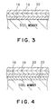
- Fig. 4 shows a multilayer coating formed on the surface of a base for a fuel delivery pipe in a second embodiment according to the present invention and consisting of a plated Ni film 22, a plated Zn-Ni alloy film 16, a plated Zn film 18 and a trivalent chromate coating formed in that order on the surface of the base.
- the plated Ni film 22 is formed in a thickness of 3 ⁇ m or above by an electroplating process that immerses a fuel delivery pipe 10 in a Ni-plating bath
- the plated Ni film 22 as the bottom layer improves the corrosion resistance of the fuel delivery pipe.
- the present invention is applicable to other piping members of an automotive fuel line, such as tubes each having an end part to be pressed in another member.
- the adhesion of the trivalent chromate coating as an alternative to a hexavalent chromate coating to a plated film can be increase, and the smoothness of the surface of the trivalent chromate coating can be improved.
- the injector namely, a member to be combined with the piping member
- the fuel delivery pipe can be coated with the multilayer coating according to the present invention
- the injector namely, a member to be combined with the piping member
- the fuel delivery pipe can be combined with the fuel delivery pipe by press fitting without damaging a sealing member, such as an O ring.
Landscapes
- Chemical & Material Sciences (AREA)
- Engineering & Computer Science (AREA)
- Mechanical Engineering (AREA)
- Chemical Kinetics & Catalysis (AREA)
- Materials Engineering (AREA)
- Metallurgy (AREA)
- Organic Chemistry (AREA)
- Inorganic Chemistry (AREA)
- General Engineering & Computer Science (AREA)
- Electrochemistry (AREA)
- Combustion & Propulsion (AREA)
- Ceramic Engineering (AREA)
- Other Surface Treatments For Metallic Materials (AREA)
- Fuel-Injection Apparatus (AREA)
- Electroplating Methods And Accessories (AREA)
- Chemical Treatment Of Metals (AREA)
Abstract
Description
Claims (4)
- A piping member for an automotive fuel line, coated with a multilayer coating including a chromate coating as a top layer;
characterized in that multilayer coating comprises a plated Zn-Ni alloy film as a bottom layer, a plated Zn film as an intermediate layer overlying the plated Zn-Ni alloy layer, and a trivalent chromate layer as a top layer overlying the plated Zn film. - The piping member for an automotive fuel line according to claim 1 characterized in that the multilayer coating further comprises a plated Ni film underlying the plated Zn-Ni alloy film.
- The piping member for an automotive fuel line according to claim 1 is a fuel delivery pipe provided with cups in which injectors are inserted by press fitting.
- The piping member for an automotive fuel line according to claim 1, wherein the plated Zn-Ni alloy film ha a thickness between t and 10 µm, the plated Zn film has a thickness between 5 and 10 Mm, and the trivalent chromate coating has a thickness between 0.1 and 1.0 µm.
Applications Claiming Priority (3)
| Application Number | Priority Date | Filing Date | Title |
|---|---|---|---|
| JP2002215209A JP2004052093A (en) | 2002-07-24 | 2002-07-24 | Multilayer plating automotive fuel piping parts |
| JP2002215209 | 2002-07-24 | ||
| PCT/JP2003/009203 WO2004009871A1 (en) | 2002-07-24 | 2003-07-18 | Multilayer plated fuel line parts for automobile |
Publications (2)
| Publication Number | Publication Date |
|---|---|
| EP1536037A1 true EP1536037A1 (en) | 2005-06-01 |
| EP1536037A4 EP1536037A4 (en) | 2007-07-11 |
Family
ID=30767916
Family Applications (1)
| Application Number | Title | Priority Date | Filing Date |
|---|---|---|---|
| EP03741513A Withdrawn EP1536037A4 (en) | 2002-07-24 | 2003-07-18 | PLATE MULTILAYER PARTS OF FUEL PIPES FOR AUTOMOTIVE |
Country Status (6)
| Country | Link |
|---|---|
| US (1) | US20050236060A1 (en) |
| EP (1) | EP1536037A4 (en) |
| JP (1) | JP2004052093A (en) |
| CN (1) | CN1332066C (en) |
| MX (1) | MXPA05000348A (en) |
| WO (1) | WO2004009871A1 (en) |
Cited By (2)
| Publication number | Priority date | Publication date | Assignee | Title |
|---|---|---|---|---|
| EP2784188A1 (en) * | 2013-03-26 | 2014-10-01 | ATOTECH Deutschland GmbH | Process for corrosion protection of iron containing materials |
| EP3277866B1 (en) | 2015-03-30 | 2020-07-22 | Benteler Steel/Tube GmbH | Pipe product and method for producing same |
Families Citing this family (13)
| Publication number | Priority date | Publication date | Assignee | Title |
|---|---|---|---|---|
| US7514153B1 (en) * | 2005-03-03 | 2009-04-07 | The United States Of America As Represented By The Secretary Of The Navy | Method for deposition of steel protective coating |
| JP4557889B2 (en) * | 2006-01-05 | 2010-10-06 | 株式会社共立精機 | Ball stud |
| DE102006035233A1 (en) * | 2006-07-26 | 2008-01-31 | Mahle International Gmbh | Galvanic surface coating of a component |
| KR101027791B1 (en) * | 2009-08-11 | 2011-04-07 | 주식회사 케피코 | Mounting Structure of Direct Fuel Rail |
| JP5773515B2 (en) * | 2010-07-23 | 2015-09-02 | 臼井国際産業株式会社 | Steel fuel pumping pipe |
| US9700928B2 (en) * | 2010-08-06 | 2017-07-11 | Toyo Kohan Co., Ltd. | Steel plate for producing pipe highly resistant to fuel vapor corrosion, pipe using same and method for producing pipe |
| JP6004521B2 (en) * | 2012-07-04 | 2016-10-12 | 臼井国際産業株式会社 | Piping with heat- and corrosion-resistant plating layer with excellent workability |
| KR101449203B1 (en) * | 2012-12-27 | 2014-10-13 | 현대자동차주식회사 | Coating method and coating layer for hose fitting of brake |
| CN105188457B (en) * | 2013-04-09 | 2017-12-01 | Ykk株式会社 | Slide fastener members alloy and slide fastener members |
| CN103912427A (en) * | 2014-04-04 | 2014-07-09 | 含山县全兴内燃机配件有限公司 | Oil injector |
| EP3153698B8 (en) * | 2015-10-07 | 2019-12-18 | CPT Group GmbH | Fuel rail assembly |
| JP6713755B2 (en) * | 2015-11-18 | 2020-06-24 | 三桜工業株式会社 | Fuel distribution pipe |
| JP2023042275A (en) * | 2021-09-14 | 2023-03-27 | 三桜工業株式会社 | fuel distribution pipe |
Family Cites Families (31)
| Publication number | Priority date | Publication date | Assignee | Title |
|---|---|---|---|---|
| US4457280A (en) * | 1982-05-04 | 1984-07-03 | Sharon Manufacturing Company | Fuel injection rail assembly |
| JPS60165387A (en) * | 1984-02-06 | 1985-08-28 | Maruyasu Kogyo Kk | Thin-film corrosion-resistant laminate plated steel pipe |
| JPS62278298A (en) * | 1985-08-28 | 1987-12-03 | Kawasaki Steel Corp | Chromated zn or zn alloy plated steel sheet and its production |
| US4885215A (en) * | 1986-10-01 | 1989-12-05 | Kawasaki Steel Corp. | Zn-coated stainless steel welded pipe |
| JPH064311B2 (en) * | 1989-02-27 | 1994-01-19 | 川崎製鉄株式会社 | Organic coated steel sheet with excellent corrosion resistance |
| JPH0696778B2 (en) * | 1990-10-05 | 1994-11-30 | 新日本製鐵株式会社 | Chromate treatment method for galvanized steel sheet |
| JPH05106058A (en) * | 1991-10-18 | 1993-04-27 | Kawasaki Steel Corp | Highly corrosion-resistant surface-treated steel sheet for fuel containers |
| DE4325980C2 (en) * | 1993-08-03 | 2003-06-26 | Bosch Gmbh Robert | Device for the common electrical contacting of several electrically excitable units of internal combustion engines |
| US5590691A (en) * | 1994-05-02 | 1997-01-07 | Itt Corporation | Extruded multiple plastic layer coating bonded to a metal tube |
| US5520223A (en) * | 1994-05-02 | 1996-05-28 | Itt Industries, Inc. | Extruded multiple plastic layer coating bonded to the outer surface of a metal tube having an optical non-reactive inner layer and process for making the same |
| US6500565B2 (en) * | 1994-08-30 | 2002-12-31 | Usui Kokusai Sangyo Kaisha Limited | Corrosion resistant resin coating structure in a metal tube |
| JP3445858B2 (en) * | 1994-12-29 | 2003-09-08 | 臼井国際産業株式会社 | Automotive metal piping with a protective coating layer |
| TWI221861B (en) * | 1998-04-22 | 2004-10-11 | Toyo Boseki | Agent for treating metallic surface, surface-treated metal material and coated metal material |
| US6387538B1 (en) * | 1998-12-01 | 2002-05-14 | Pohang Iron & Steel Co., Ltd. | Surface-treated steel sheet for fuel tanks and method of fabricating same |
| EP1032100B1 (en) * | 1999-02-25 | 2002-10-02 | Ngk Spark Plug Co., Ltd | Glow plug and spark plug, and manufacturing method therefor |
| JP4286398B2 (en) * | 1999-08-25 | 2009-06-24 | 日本特殊陶業株式会社 | Spark plug and manufacturing method thereof |
| JP4391650B2 (en) * | 1999-12-24 | 2009-12-24 | 日本特殊陶業株式会社 | Spark plug for internal combustion engine |
| CN1258763A (en) * | 1999-12-30 | 2000-07-05 | 上海交通大学 | Zinc-nickel alloy electroplating process using alkali electroplating liquid |
| US6976510B2 (en) * | 2000-01-19 | 2005-12-20 | Itt Manufacturing Enterprises, Inc. | Corrosion resistant metal tube and process for making the same |
| MY117334A (en) * | 2000-11-10 | 2004-06-30 | Nisshin Steel Co Ltd | Chemically processed steel sheet improved in corrosion resistance |
| DE10297178B4 (en) * | 2001-09-05 | 2016-11-03 | Usui Kokusai Sangyo Kaisha, Ltd. | Corrosion-resistant coating film structure containing no hexavalent chromium |
| US6601564B2 (en) * | 2001-09-26 | 2003-08-05 | Senior Investments Ag | Flexible fuel rail |
| JP3969247B2 (en) * | 2001-11-06 | 2007-09-05 | 株式会社デンソー | Fuel injection valve |
| JP3332374B1 (en) * | 2001-11-30 | 2002-10-07 | ディップソール株式会社 | A treatment solution for forming a hexavalent chromium-free rust preventive film on zinc and zinc alloy plating, a hexavalent chromium-free rust preventive film, and a method for forming the same. |
| JP3332373B1 (en) * | 2001-11-30 | 2002-10-07 | ディップソール株式会社 | A treatment solution for forming a hexavalent chromium-free rust preventive film on zinc and zinc alloy plating, a hexavalent chromium-free rust preventive film, and a method for forming the same. |
| US6651627B2 (en) * | 2001-12-12 | 2003-11-25 | Millennium Industries Corp. | Fuel rail pulse damper |
| US6725839B2 (en) * | 2002-05-29 | 2004-04-27 | Millennium Industries Corp. | Stamped metal fuel rail |
| US7051961B2 (en) * | 2002-06-07 | 2006-05-30 | Synerject, Llc | Fuel injector with a coating |
| US6761150B2 (en) * | 2002-11-05 | 2004-07-13 | Millennium Industries Corp. | Fuel rail flow-feed pulse damper |
| US20050031894A1 (en) * | 2003-08-06 | 2005-02-10 | Klaus-Peter Klos | Multilayer coated corrosion resistant article and method of production thereof |
| US7028668B1 (en) * | 2004-12-21 | 2006-04-18 | Robert Bosch Gmbh | Self-damping fuel rail |
-
2002
- 2002-07-24 JP JP2002215209A patent/JP2004052093A/en active Pending
-
2003
- 2003-07-18 CN CNB038174650A patent/CN1332066C/en not_active Expired - Lifetime
- 2003-07-18 MX MXPA05000348A patent/MXPA05000348A/en active IP Right Grant
- 2003-07-18 US US10/519,602 patent/US20050236060A1/en not_active Abandoned
- 2003-07-18 EP EP03741513A patent/EP1536037A4/en not_active Withdrawn
- 2003-07-18 WO PCT/JP2003/009203 patent/WO2004009871A1/en not_active Ceased
Cited By (3)
| Publication number | Priority date | Publication date | Assignee | Title |
|---|---|---|---|---|
| EP2784188A1 (en) * | 2013-03-26 | 2014-10-01 | ATOTECH Deutschland GmbH | Process for corrosion protection of iron containing materials |
| WO2014154366A1 (en) * | 2013-03-26 | 2014-10-02 | Atotech Deutschland Gmbh | Process for corrosion protection of iron containing materials |
| EP3277866B1 (en) | 2015-03-30 | 2020-07-22 | Benteler Steel/Tube GmbH | Pipe product and method for producing same |
Also Published As
| Publication number | Publication date |
|---|---|
| WO2004009871A1 (en) | 2004-01-29 |
| EP1536037A4 (en) | 2007-07-11 |
| JP2004052093A (en) | 2004-02-19 |
| CN1332066C (en) | 2007-08-15 |
| US20050236060A1 (en) | 2005-10-27 |
| MXPA05000348A (en) | 2005-08-19 |
| CN1671886A (en) | 2005-09-21 |
Similar Documents
| Publication | Publication Date | Title |
|---|---|---|
| EP1536037A1 (en) | Multilayer plated fuel line parts for automobile | |
| EP0913252B1 (en) | Steel plate for highly corrosion-resistant fuel tank | |
| KR100530285B1 (en) | Hexavalent chromium-free surface-treating agent for sn- or al-based coated steel sheet, and surface treated steel sheet | |
| AU718855B2 (en) | Rustproof steel sheet for automobile fuel tank with excellent resistance weldability corrosion resistance and press moldability | |
| US6143422A (en) | Surface-treated steel sheet having improved corrosion resistance after forming | |
| CN107208278B (en) | steel sheet for fuel tank | |
| JP3944129B2 (en) | Surface-treated steel sheet for containers with excellent weldability, corrosion resistance, and paint adhesion | |
| JPWO2007052683A1 (en) | Steel pipe for automobile piping | |
| JPH0243040A (en) | Lubricating resin treated steel plate excellent in corrosion resistance | |
| RU2704778C1 (en) | Electrodeposition device | |
| JP3849398B2 (en) | Surface-treated steel sheet for fuel containers with excellent corrosion resistance of deteriorated gasoline | |
| JP3847921B2 (en) | Steel plate for high corrosion resistant fuel tank | |
| JP2985772B2 (en) | Surface-treated steel sheet with excellent corrosion resistance after processing | |
| JPH0494771A (en) | Lubricant thin film resin steel sheet excellent in corrosion resistance and weldability | |
| JPH0849090A (en) | Surface-treated steel sheet for fuel tanks with excellent corrosion resistance and workability | |
| JP2010012974A (en) | Fuel feeding pipe | |
| JPH0760897A (en) | Lubricating black steel plate | |
| AU2023425429A1 (en) | Oil-Well Metal Pipe | |
| JPH0274333A (en) | Precoated steel plate for di can and manufacture of di can using it | |
| JPS63179083A (en) | Multi-ply alloy plated steel sheet having superior corrosion resistance and workability | |
| JP2001303231A (en) | Aluminum plated steel sheet for fuel tank | |
| JP2000313969A (en) | Steel plates for fuel tanks with excellent corrosion resistance and excellent top coat adhesion | |
| EA050029B1 (en) | METAL PIPE FOR OIL WELL | |
| JPH0617286A (en) | Method for manufacturing zinc-based plated aluminum plate | |
| JPH07305176A (en) | Lubricated steel sheet with excellent appearance, corrosion resistance and workability |
Legal Events
| Date | Code | Title | Description |
|---|---|---|---|
| PUAI | Public reference made under article 153(3) epc to a published international application that has entered the european phase |
Free format text: ORIGINAL CODE: 0009012 |
|
| 17P | Request for examination filed |
Effective date: 20050120 |
|
| AK | Designated contracting states |
Kind code of ref document: A1 Designated state(s): AT BE BG CH CY CZ DE DK EE ES FI FR GB GR HU IE IT LI LU MC NL PT RO SE SI SK TR |
|
| RBV | Designated contracting states (corrected) |
Designated state(s): DE ES FR GB HU TR |
|
| A4 | Supplementary search report drawn up and despatched |
Effective date: 20070611 |
|
| RIC1 | Information provided on ipc code assigned before grant |
Ipc: C25D 5/10 20060101ALI20070604BHEP Ipc: C23C 22/30 20060101ALI20070604BHEP Ipc: C25D 3/22 20060101ALI20070604BHEP Ipc: C25D 3/56 20060101ALI20070604BHEP Ipc: C23C 28/00 20060101AFI20070604BHEP Ipc: F02M 55/02 20060101ALI20070604BHEP Ipc: C23C 22/53 20060101ALI20070604BHEP |
|
| STAA | Information on the status of an ep patent application or granted ep patent |
Free format text: STATUS: THE APPLICATION HAS BEEN WITHDRAWN |
|
| 18W | Application withdrawn |
Effective date: 20070823 |