EP1535875A1 - Dispositif d'ascenseur - Google Patents
Dispositif d'ascenseur Download PDFInfo
- Publication number
- EP1535875A1 EP1535875A1 EP02765403A EP02765403A EP1535875A1 EP 1535875 A1 EP1535875 A1 EP 1535875A1 EP 02765403 A EP02765403 A EP 02765403A EP 02765403 A EP02765403 A EP 02765403A EP 1535875 A1 EP1535875 A1 EP 1535875A1
- Authority
- EP
- European Patent Office
- Prior art keywords
- car
- rope
- sheave
- deflector
- elevator system
- Prior art date
- Legal status (The legal status is an assumption and is not a legal conclusion. Google has not performed a legal analysis and makes no representation as to the accuracy of the status listed.)
- Granted
Links
Images


Classifications
-
- B—PERFORMING OPERATIONS; TRANSPORTING
- B66—HOISTING; LIFTING; HAULING
- B66B—ELEVATORS; ESCALATORS OR MOVING WALKWAYS
- B66B11/00—Main component parts of lifts in, or associated with, buildings or other structures
- B66B11/0035—Arrangement of driving gear, e.g. location or support
- B66B11/0045—Arrangement of driving gear, e.g. location or support in the hoistway
-
- B—PERFORMING OPERATIONS; TRANSPORTING
- B66—HOISTING; LIFTING; HAULING
- B66B—ELEVATORS; ESCALATORS OR MOVING WALKWAYS
- B66B11/00—Main component parts of lifts in, or associated with, buildings or other structures
- B66B11/0065—Roping
- B66B11/008—Roping with hoisting rope or cable operated by frictional engagement with a winding drum or sheave
-
- B—PERFORMING OPERATIONS; TRANSPORTING
- B66—HOISTING; LIFTING; HAULING
- B66B—ELEVATORS; ESCALATORS OR MOVING WALKWAYS
- B66B15/00—Main component parts of mining-hoist winding devices
- B66B15/02—Rope or cable carriers
- B66B15/04—Friction sheaves; "Koepe" pulleys
Definitions
- the present invention relates to an elevator system in which a driving device is disposed at an upper portion in a hoistway.
- This invention was devised to solve problems such as those mentioned above, and has its object to secure a low-priced and stable life of the main rope, by using general -purpose ropes. Another object is to minimize the length of the hoistway by contriving ways of suspending the car.
- the elevator system in the present invention comprises: a driving device provided on a support bench disposed in an upper part of a hoistway, the driving device including a drive sheave with a main elevator rope passed around and an electric motor for rotating the drive sheave, with at least the rotation axis of the drive sheave arranged in vertical direction; and a car and a counter weight suspended by the main rope in the hoistway and ascended and descended by the driving device.
- This elevator system comprises: an idler pulley with its axis of rotation arranged vertically at a predetermined distance from the driving device; and a main rope with one end connected to the counter weight, the middle part passed around the drive sheave, then around the idler pulley and again around the drive sheave, and the other end connected to the car.
- a deflector sheave for the car that is disposed on a support bench and changes the direction of the part of the main rope extending from the drive sheave to the car from the horizontal direction to the vertical direction
- a deflector sheave for the counter weight that is similarly disposed on a support bench and changes the direction of the part of the main rope extending from the drive sheave to the counter weight from the horizontal direction to the vertical direction.
- this driving device is formed so as to be thinner in the rotational axis direction compared to the radial direction in outer shape, and the drive sheave has a U-groove around which the main rope is passed, and the diameter of the semicircle at the bottom part of this U-groove is made so as to approximate the diameter of the main rope. Also, the driving device is arranged near the corner of the back part of the hoistway.
- first rope for the first path there is a first rope for the first path, and a second rope for the second path, both ropes independent of one another.
- first deflector sheave for the car for the first rope and a second deflector sheave for the car for the second rope, and they are arranged so that they are apart from each other and that at least one part of them overlaps the car in vertical projection area in the hoistway.
- at least one part of the deflector sheave for the counter weight overlaps the counter weight in vertical projection area in the hoistway.
- one end of both the first rope and the second rope are made to change direction from the drive sheave by the deflector sheave for the counter weight, and are connected to the counter weight.
- first and second ropes are made to change direction from the drive sheave respectively by a first deflector sheave for the car and a second deflector sheave for the car, and the ends of the first and second ropes are both connected to the car at lower parts of the sides of the car that are opposite to each other.
- the two ends are connected at positions that are opposite to each other across the center of gravity of the car.
- the idler pulley is arranged so that it is placed between a part of the main rope extending from the drive sheave to the deflector sheave for the car and a part of the main rope extending from the drive sheave to the deflector sheave for the counter weight.
- the elevator system in the present invention comprises a control panel to control the car and a governor, and the control panel, the governor and the idler pulley are positioned not to exceed the range of the maximum height dimension of any of the driving device, or the deflector sheave for the car and the deflector sheave for the counter weight.
- the elevator system in the present invention comprises main guide rails to guide the car and sub-guide rails to guide the counter weight
- the support bench is supported by at least any of: the main guide rails and the sub-guide rails, or the hoistway wall.
- the support bench is disposed interposing an anti-vibration material between the main guide rails and the sub-guide rails, or the hoistway wall.
- the idler pulley is arranged at a predetermined position from the driving device, it is possible to increase the degrees of the hoisting angle of the main rope to the drive sheave, and it becomes easier to secure frictional force between the main rope and the drive sheave. Therefore, a general-purpose rope can be used without the necessity to use a special high-friction main rope, and it is possible to secure a low-priced and stable life of the main ropes, and moreover, it facilitates maintenance and inspection of the main rope.
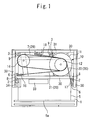
- Figures 1 and 2 are views showing an example of an arrangement of the machineroom-less elevator system in accordance with the first embodiment of the present invention
- Figure 1 is a plan view of the elevator system viewed from the upper side
- Figure 2 is a partial elevation of the elevator system viewed from the horizontal direction
- both are conceptual maps showing the major components of the elevator system.
- a car 5 is made to ascend and descend throughout the hoistway 1 guided by the main guide rails 2, and a counter weight 7 is made to ascend and descend throughout the hoistway 1 guided by the sub-guide rails 3.
- the car 5 has an entrance 5a at the front part of the hoistway as shown in the plan view of Figure 1; the main guide rails 2 are disposed near both sides of the surfaces that are orthogonal to the entrance surface, and the sub-guide rails 3 are disposed near the side of the rear surface that is opposite to the car entrance. Moreover, a plurality of guide shoes 8 that are coupled to the main guide rails 2 are disposed on the car 5, and a plurality of guide shoes 9 that are engaged with the sub-guide rails 3 are disposed on the counter weight 7. On each of the upper ends of the main guide rails 2 and the sub-guide rails 3, support bench brackets 31 are mounted for fixing support benches 30, and the support bench 30 is fixed to the support bench brackets 31 via an anti-vibration material 32.
- the support bench 30 may be fixed directly to the support bench brackets 31, but in order to prevent vibration generated by the driving device 10 from being transmitted to the building from the hoistway walls via the main guide rails 2, the sub-guide rails 3 and the rail brackets 4, it is preferable to be used with an anti-vibration material 32 interposed between the support bench brackets 31.
- the drive sheave 12, around which the main rope 20 is passed and is constructed so that the rotation axis is in the vertical direction, and the driving device 10, which comprises an electric motor 11 that rotates and drives the drive sheave 12, are thin-type, formed so as to be thinner in the rotational axis direction compared to the radial direction in outer shape.
- the idler pulley 14 is arranged so that the rotation axis is in the vertical direction, as is the drive sheave 12.
- the driving device 10 and the idler pulley 14 are loaded on the support bench 30, the driving device 10 is mounted on an upper part of the car 5, and the idler pulley 14 is arranged at a predetermined distance from the driving device 10.
- the driving device 10 is positioned near a corner of the hoistway 1, and the idler pulley 14 is positioned near another corner of the hoistway 1. Moreover, in Figure 1, the driving device 10 is in a desirable position (a position in which there is no fear of crossing of the main rope and occurrence of interference through the process of passing the main rope around the sheaves) from the viewpoint of roping, i.e. near a corner at the rear part of the hoistway.
- the idler pulley 14 may also be mounted on a support bench provided separately from the support bench 30.
- the main rope 20 has two parallel paths which includes a first independent rope 21 and a second independent rope 22, and the first rope 21 and the second rope 22 both comprise a set of unit ropes made of a plurality of ropes.
- the intermediate part of the main rope 20, which includes the first rope 21 and the second rope 22, is passed around the drive sheave 12, then around the idler pulley 14, and again around the drive sheave 12.
- One end of the main rope 20 is made to change direction from the horizontal direction to the vertical direction by the deflector sheave 18 for the counter weight, and extends from the drive sheave 12 to the counter weight 7. That is, the first rope 21 and the second rope 22 are parallel to each other and form a main rope 20 while being passed around the idler pulley 14 from the drive sheave 12, being passed around the drive sheave 12, and then being passed over to the counter weight 7 from the deflector sheave 18 for the counter weight.
- first rope 21 and the second rope 22 are connected to an upper beam 29 of the counter weight 7 interposing a rope shackle 26 and a buffer material 27 using a coil spring
- each of the first rope 21 and the second rope 22 are connected to two car brackets 6 which are provided at the bottom portions of the car 5 that are opposite to each other across the center of gravity of the car 5, via a rope shackle 24 and a buffer material 25 using a coil spring.
- the car 5 is supported by the bottom portion of the car 5
- the reduction in vertical dimension of the hoistway 1 may be realized by supporting the car 5 at two points lower than the top surface of the car, the supporting positions may be anywhere as long as they are in the sides of the car 5 that are opposite to each other.
- a deflector sheave for the car As a deflector sheave for the car, a first deflector sheave 16 for the car and a second deflector sheave 17 for the car are provided respectively to the first rope 21 and the second rope 22, and they are arranged so that they are apart from each other, and also that at least one part of them overlap the car 5 in vertical projection area in the hoistway 1. Furthermore, the first deflector sheave 16 for the car and the second deflector sheave 17 for the car are arranged at an upper portion of the rope shackle 24.
- first deflector sheave 16 for the car and the second deflector sheave 17 for the car overlaps the car 5 in vertical projection area, thus they are arranged so that there is no necessity to secure a long distance between the car 5 and the hoistway wall (so that there is no necessity to enlarge the plane of the hoistway 1).
- the deflector sheave 18 for the counter weight is provided so that at least one part of it overlaps the counter weight 7 in vertical projection area in the hoistway 1.
- the first deflector sheave 16 for the car, the second deflector sheave 17 for the car and the deflector sheave 18 for the counter weight are mounted on the support bench 30.
- the idler pulley 14 is arranged so that it is between the main rope 20 (the first rope 21) extending from the drive sheave 12 to the first deflector sheave 16 for the car, and the main rope 20 extending from the drive sheave 12 to the deflector sheave 18 for the counter weight.
- the drive sheave 12, the idler pulley 14, the first deflector sheave 16 for the car, the second deflector sheave 17 for the car, and the deflector sheave 18 for the counter weight so that there is no fear of crossing of the main rope 20 and occurrence of interference during the process of passing the main rope 20 around them in the order of structure.
- the car 5 is to be suspended by the sides of the car 5 that are opposite to each other, it is preferable to suspend the car 5 at positions that are opposite to each other across the center of gravity of the car 5, and in that case, the two suspension points of the car 5 will be near the side walls of almost the middle of the hoistway 1 (near the main guide rails 2) at vertical direction view of the hoistway 1, as shown in Figure 1.
- the idler pulley 14 in the abovementioned manner makes it possible to store apparatus provided at the upper part of the hoistway such as the driving device 10, idler pulley 14, the first deflector sheave 16 for the car, the second deflector sheave 17 for the car and the deflector sheave 18 for the counter weight which are mounted on the support bench 30 at one side of the hoistway when viewed in vertical projection area in one side of the hoistway 1, based on a line obtained by connecting the attaching positions of the first deflector sheave 16 for the car and the second deflector 17 for the car as a standard line, and this secures saving of space at the upper part of the hoistway 1, reduces the size of the support bench 30 and secures space for maintenance.
- apparatus provided at the upper part of the hoistway such as the driving device 10, idler pulley 14, the first deflector sheave 16 for the car, the second deflector sheave 17 for the car and the deflector sheave 18 for the counter weight which are mounted
- the idler pulley 14 may also be arranged so that it becomes between the main rope 20 extending from the drive sheave 12 to the second deflector sheave 17 for the car (the second rope 22), the main rope 20 extending from the drive sheave 12 to the deflector sheave 18 for the counterweight (specifically, between the main rope 20 extending from the drive sheave 12 to the deflector sheave 16 for the car (the first rope 21), the main rope 20 extending from the drive sheave 12 to the second deflector 17 for the car (the second rope 22) ).
- a control panel 33 for controlling ascents and descents of the car 5 and a governor 34 are mounted on the support bench 30, and the control panel 33, the governor 34 and the idler pulley 14 are provided so that they fit in the maximum height dimension of any of the driving device 10, the first deflector sheave 16 for the car, the second deflector sheave 17 for the car and the deflector sheave 18 for the counter weight. In Figure 2, they are positioned so that they stay within the height range of the driving device 10.
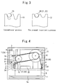
- Figure 3 are sectional views showing the conventional and the present invention's drive sheaves grooves.
- the main rope 20 is passed around the drive sheave 12, it is passed around the idler pulley 14, and then passed around the drive sheave 12 again, thus making the hoisting angle which indicates the contact amount of the drive sheave 12 and the main rope 20 increase, and making it easy to obtain the predetermined traction.
- the present invention has a steel general -purpose main rope 20 and a drive sheave 12 with a U-groove around which the main rope 20 passes and of which the diameter of the semicircle at the bottom part is made so as to approximate the diameter of the main rope 20, thus making it possible that the necessary traction can be provided, and this leads to long life of the main rope 20 and moreover, to reduction of the cost at the time of manufacturing and inspection.
- the driving device 10 is disposed on an upper part of a corner of the car 5, and the diameter of the idler pulley 14 is generally the same as the diameter of the drive sheave 12 or around 90% of it, and the idler pulley 14 is disposed at a predetermined distance from the driving device 10.
- the drive sheave 12 is placed at a corner in the hoistway 1 so that it would be the utmost far position from the other sheaves (i.e., the idler pulley 14, the first deflector sheave 16 for the car, the second deflector sheave 17 for the car and the deflector sheave 18 for the counter weight), it is possible to keep a sufficient distance to relieve the twist between the drive sheave 12 and the other sheaves which are different in axial direction, and also to secure a sufficient angle of hoisting for the drive sheave 12.
- the other sheaves i.e., the idler pulley 14, the first deflector sheave 16 for the car, the second deflector sheave 17 for the car and the deflector sheave 18 for the counter weight
- control panel 33, the governor 34, the idler pulley 14, and in addition, the first deflector sheave 16 for the car, the second deflector sheave 17 for the car and the deflector sheave 18 for the counter weight are disposed so that they do not exceed the maximum height dimension of the driving device 10, besides, the support bench 30 may also be disposed in the abovementioned dimension, thus miniaturizing the upper part of the hoistway 1. Moreover, it is not only the driving device 10 that indicates the maximum height dimension; for example, one of the first deflector 16 for the car, the second car 17 for the car and the deflector sheave 18 for the counter weight could also be so.
- a high-tension thin rope may be used to obtain further traction ability.
- the relation between the diameter of the sheave and the diameter of the main rope is diameter of the sheave/diameter of the main rope ⁇ 40, so, by using a high-tension rope which is smaller in diameter than the conventional main rope, sheaves such as the drive sheave 12, the idler pulley 14, the first deflector sheave 16 for the car, the second deflector sheave 17 for the car and the deflector sheave 18 for the counter weight may be miniaturized, and also the driving device 10 my be miniaturized, so space-saving in the upper part of the hoistway 1 will improve.
- Figure 4 is a plan view showing an example of an arrangement of the machineroom-less elevator system in accordance with the second embodiment of the present invention.
- the counter weight 7 is disposed behind the car 5 in the hoistway 1, however, as in Figure 4, a counter weight 7 is disposed at one side of the car 5 in the hoistway 1. That is, when the counter weight 7 is viewed from an entrance 5a of the car 5, the counter weight 7 is made to ascend and descend along one side of the car 5, so also the sub-guide rails 3 are disposed at a side of the hoistway (in this case, the left side) when viewed from an entrance of the hoistway.
- the form of the support bench 30 also changes.
- the idler pulley 14 is arranged so that it is between the main rope 20 (the first rope 21) extending from the drive sheave 12 to the first deflector sheave 16 for the car, and the main rope 20 extending from the drive sheave 12 to the deflector sheave 18 for the counter weight.
- the main rope 20 is passed around the drive sheave 12, it is passed around the idler pulley 14, and then passed around the drive sheave 12 again, thus making the hoisting angle which indicates the contact amount of the drive sheave 12 and the main rope 20 increase, and making it easy to obtain the predetermined traction.
- the car 5 is supported below at two points below the car 5, thus making it possible to reduce the strength of the structural members of the upper portion of the car 5, and also to reduce the weight and the manufacturing cost of the car 5.
- Figures 5 and 6 are plan views showing an example of an arrangement of the machineroom-less elevator system in accordance with the third embodiment of the present invention.
- the main rope 20 is comprised of a first rope 21 and a second rope 22, and is made to change direction of the part of the rope extending from the drive sheave 12 to the deflector sheave 16 for the car, and from the drive sheave 12 to deflector sheave 17 for the car, and the car 5 is supported by two brackets 6 at the bottom of the car 5.
- the present invention is not limited only to these features.
- a main rope 20 of only one path is passed around a drive sheave 12, passed around the idler pulley 14, and then passed around the drive sheave 12.
- One end of the main rope 20 is made to change direction from the horizontal direction to the vertical direction by a deflector 18 for the counter weight, and extends to the counter weight 18.
- the other end of the main rope 20 extending from the drive sheave 12 to the car 5 is changed from the direction of the horizontal direction to the vertical direction by the deflector 15 for the car, and is connected to an upper beam 28 of the car 5 via a rope shackle 24 and a buffer material 25 (figure omitted).
- the present invention may be applied also to a roping method in which the car 5 is supported by only point of the upper beam 28.
- a sufficient angle of hoisting and facilitates to secure the necessary traction (as in PCT international publication No. WO 02/16247 A1,) without using a special high-friction main rope 23 and a drive sheave 13 with an undercut groove, the use of general-purpose rope 20 becomes possible, thus making the life of the main rope longer, and reducing the manufacturing and inspection costs lower.
- the counter weight 7 is provided behind the car 5 in the hoistway 1, however, the present invention is also applicable for elevator systems in which the counter weight 7 is provided on the side of the car 5 in the hoistway 1, as shown in Figure 6.
- the support bench 30 on which the driving device 10, the idler pulley 14, the first deflector sheave 16 for the car, the second deflector sheave 17 for the car (the deflector sheave 15 for the car) and the deflector sheave 18 for the counter weight are disposed is fixed to the support bench brackets 31 provided on the main guide rails 2 and the sub-guide rails 3, via the anti-vibration material 32.
- hoistway walls are formed so as to be strength members, and as an example of variants of these embodiments, the support bench 30 on which the driving device 10, the idler pulley 14, the first deflector sheave 16 for the car, the second deflector sheave 17 for the car (the deflector sheave 15 for the car) and the deflector sheave 18 for the counter weight are disposed, may also be supported by a hoistway wall (figure omitted). Further, by putting an anti-vibration rubber material 32 between the support bench 30 and the hoistway wall, it is possible to prevent the vibration generated by the driving device 10 from transmitting to the wall.
- the present invention is composed as explained above and has the following effects.
- the idler pulley by disposing the idler pulley at a predetermined place from the driving device, it is possible to increase the hoisting angle of the main rope to the drive sheave, and the friction between the main rope and the drive sheave, so it is possible to use a general-use rope instead of using a special high-friction main rope, thus securing a low-priced and stable life of a main rope. Also, it facilitates maintenance and inspection of the main ropes. Moreover, usage of a high-tension fine main rope may be used to miniaturize the diameters of the drive sheave, idler pulley and the deflector sheaves.
- the present invention is suitable for elevators which are to be provided at difficult social conditions of a location where there are limitations such as the appearance or the outlook in installation space of elevators due to the external appearance or height of buildings.
Applications Claiming Priority (1)
| Application Number | Priority Date | Filing Date | Title |
|---|---|---|---|
| PCT/JP2002/008914 WO2004022471A1 (fr) | 2002-09-03 | 2002-09-03 | Dispositif d'ascenseur |
Publications (3)
| Publication Number | Publication Date |
|---|---|
| EP1535875A1 true EP1535875A1 (fr) | 2005-06-01 |
| EP1535875A4 EP1535875A4 (fr) | 2011-04-06 |
| EP1535875B1 EP1535875B1 (fr) | 2013-02-27 |
Family
ID=31972294
Family Applications (1)
| Application Number | Title | Priority Date | Filing Date |
|---|---|---|---|
| EP02765403A Expired - Fee Related EP1535875B1 (fr) | 2002-09-03 | 2002-09-03 | Dispositif d'ascenseur |
Country Status (4)
| Country | Link |
|---|---|
| EP (1) | EP1535875B1 (fr) |
| JP (1) | JP4216252B2 (fr) |
| CN (1) | CN1297468C (fr) |
| WO (1) | WO2004022471A1 (fr) |
Cited By (3)
| Publication number | Priority date | Publication date | Assignee | Title |
|---|---|---|---|---|
| WO2019076655A1 (fr) * | 2017-10-17 | 2019-04-25 | Inventio Ag | Installation d'ascenseur dotée d'éléments de renvoi ayant des rainures à géométries différentes |
| US10745245B2 (en) | 2016-08-02 | 2020-08-18 | Otis Elevator Company | Governor assembly and elevator |
| US10941020B2 (en) | 2018-01-30 | 2021-03-09 | Otis Elevator Company | Deflector sheave bracket for offset bedplate |
Families Citing this family (6)
| Publication number | Priority date | Publication date | Assignee | Title |
|---|---|---|---|---|
| JP4762907B2 (ja) * | 2004-10-13 | 2011-08-31 | 三菱電機株式会社 | エレベータ装置 |
| KR100766654B1 (ko) * | 2006-06-23 | 2007-10-15 | 미쓰비시덴키 가부시키가이샤 | 엘리베이터 장치 |
| FI125130B (fi) * | 2012-01-27 | 2015-06-15 | Kone Corp | Laitteisto hissin nostokoneiston kiinnittämiseksi ja kiinnitysjärjestely |
| US11305966B2 (en) | 2016-05-17 | 2022-04-19 | Inventio Ag | Method and device for detecting damage in a support for an elevator system |
| CN108125471B (zh) * | 2017-12-20 | 2021-09-28 | 合肥市东庐机械制造有限公司 | 一种矿山机械配件展示架 |
| US11254540B2 (en) * | 2017-12-20 | 2022-02-22 | Mitsubishi Electric Corporation | Machine-room-less elevator |
Citations (4)
| Publication number | Priority date | Publication date | Assignee | Title |
|---|---|---|---|---|
| DE2441992A1 (de) * | 1973-09-07 | 1975-04-03 | Hitachi Ltd | Aufzug |
| EP1018480A2 (fr) * | 1999-01-08 | 2000-07-12 | Mitsubishi Denki Kabushiki Kaisha | Câblage et emplacement machinerie pour ascenseur |
| EP1057771A2 (fr) * | 1999-06-03 | 2000-12-06 | Mitsubishi Denki Kabushiki Kaisha | Placement d'une machinerie de levage |
| ES2161183A1 (es) * | 1998-12-22 | 2001-11-16 | Otis Elevator Co | "maquina plana de ascensor que tiene rotacion orientada verticalmente.". |
Family Cites Families (6)
| Publication number | Priority date | Publication date | Assignee | Title |
|---|---|---|---|---|
| SE327071C (sv) * | 1969-07-21 | 1974-04-18 | T Hedstroem | Anordning för drivning av hängställning |
| JPS58117476U (ja) * | 1982-02-05 | 1983-08-10 | 三菱電機株式会社 | トラクシヨン式エレベ−タ装置 |
| FI92182C (fi) * | 1992-07-07 | 1994-10-10 | Kone Oy | Vetopyörähissi |
| DE59711862D1 (de) * | 1996-11-11 | 2004-09-23 | Inventio Ag | Aufzugsanlage mit im Aufzugsschacht angeordneter Antriebseinheit |
| DE60043310D1 (de) * | 2000-08-21 | 2009-12-24 | Mitsubishi Electric Corp | Aufzugseinrichtung |
| CN2484293Y (zh) * | 2001-06-13 | 2002-04-03 | 赵文斌 | 人力升降机 |
-
2002
- 2002-09-03 EP EP02765403A patent/EP1535875B1/fr not_active Expired - Fee Related
- 2002-09-03 JP JP2004534064A patent/JP4216252B2/ja not_active Expired - Fee Related
- 2002-09-03 CN CNB028221664A patent/CN1297468C/zh not_active Expired - Fee Related
- 2002-09-03 WO PCT/JP2002/008914 patent/WO2004022471A1/fr active Application Filing
Patent Citations (4)
| Publication number | Priority date | Publication date | Assignee | Title |
|---|---|---|---|---|
| DE2441992A1 (de) * | 1973-09-07 | 1975-04-03 | Hitachi Ltd | Aufzug |
| ES2161183A1 (es) * | 1998-12-22 | 2001-11-16 | Otis Elevator Co | "maquina plana de ascensor que tiene rotacion orientada verticalmente.". |
| EP1018480A2 (fr) * | 1999-01-08 | 2000-07-12 | Mitsubishi Denki Kabushiki Kaisha | Câblage et emplacement machinerie pour ascenseur |
| EP1057771A2 (fr) * | 1999-06-03 | 2000-12-06 | Mitsubishi Denki Kabushiki Kaisha | Placement d'une machinerie de levage |
Non-Patent Citations (1)
| Title |
|---|
| See also references of WO2004022471A1 * |
Cited By (5)
| Publication number | Priority date | Publication date | Assignee | Title |
|---|---|---|---|---|
| US10745245B2 (en) | 2016-08-02 | 2020-08-18 | Otis Elevator Company | Governor assembly and elevator |
| WO2019076655A1 (fr) * | 2017-10-17 | 2019-04-25 | Inventio Ag | Installation d'ascenseur dotée d'éléments de renvoi ayant des rainures à géométries différentes |
| AU2018351932B2 (en) * | 2017-10-17 | 2021-10-28 | Inventio Ag | Elevator system comprising deflecting elements having different groove geometries |
| US11820628B2 (en) | 2017-10-17 | 2023-11-21 | Inventio Ag | Elevator system comprising deflecting elements having different groove geometries |
| US10941020B2 (en) | 2018-01-30 | 2021-03-09 | Otis Elevator Company | Deflector sheave bracket for offset bedplate |
Also Published As
| Publication number | Publication date |
|---|---|
| CN1582252A (zh) | 2005-02-16 |
| WO2004022471A1 (fr) | 2004-03-18 |
| CN1297468C (zh) | 2007-01-31 |
| JP4216252B2 (ja) | 2009-01-28 |
| EP1535875B1 (fr) | 2013-02-27 |
| EP1535875A4 (fr) | 2011-04-06 |
| JPWO2004022471A1 (ja) | 2005-12-22 |
Similar Documents
| Publication | Publication Date | Title |
|---|---|---|
| US6598707B2 (en) | Elevator | |
| JP4490660B2 (ja) | エレベータ装置用駆動機械および駆動機械を取り付ける方法 | |
| KR100618467B1 (ko) | 엘리베이터 장치 | |
| CA2508686A1 (fr) | Montage a cables de rappel pour monte-charge | |
| JP2008156116A (ja) | 昇降路内で相互に上下に配置された2台のエレベータケージを有するエレベータ | |
| EP1481935A1 (fr) | Ascenseur | |
| EP1302430A1 (fr) | Dispositif d'ascenseur | |
| EP1535875B1 (fr) | Dispositif d'ascenseur | |
| EP1396460A2 (fr) | Système d' ascenseur | |
| US20110315487A1 (en) | Arrangement of elevator machines | |
| EP2284112B1 (fr) | Plaque de support compacte comprenant des éléments d'arrimage d'extrémité integrés, accessibles | |
| EP2108610A1 (fr) | Élévateur sans salle des machines | |
| KR20150022917A (ko) | 엘리베이터 장치 | |
| EP1828044A1 (fr) | Agencement de câblage d'ascenseur | |
| EP1512652A1 (fr) | Ascenseur | |
| JP2006016184A (ja) | Cwtレスエレベータ装置 | |
| JP2005306513A (ja) | エレベーター装置 | |
| EP1571113B1 (fr) | Equipement d'ascenseur | |
| EP1736431B1 (fr) | Appareillage d'ascenseur | |
| EP1500620A1 (fr) | Ascenseur | |
| EP1700813A1 (fr) | Systeme d'ascenseur | |
| EP1808399A2 (fr) | Ascenseur à câble élévateur doté d'un contrepoids d'entraînement | |
| JP4316507B2 (ja) | エレベータ装置 | |
| JP2011162291A (ja) | ロープ式エレベータ | |
| JPWO2003043921A1 (ja) | エレベーター装置 |
Legal Events
| Date | Code | Title | Description |
|---|---|---|---|
| PUAI | Public reference made under article 153(3) epc to a published international application that has entered the european phase |
Free format text: ORIGINAL CODE: 0009012 |
|
| 17P | Request for examination filed |
Effective date: 20040213 |
|
| AK | Designated contracting states |
Kind code of ref document: A1 Designated state(s): AT BE BG CH CY CZ DE DK EE ES FI FR GB GR IE IT LI LU MC NL PT SE SK TR |
|
| RBV | Designated contracting states (corrected) |
Designated state(s): NL |
|
| REG | Reference to a national code |
Ref country code: DE Ref legal event code: 8566 |
|
| RAP1 | Party data changed (applicant data changed or rights of an application transferred) |
Owner name: MITSUBISHI DENKI KABUSHIKI KAISHA |
|
| A4 | Supplementary search report drawn up and despatched |
Effective date: 20110307 |
|
| RIC1 | Information provided on ipc code assigned before grant |
Ipc: B66B 7/06 20060101ALI20110301BHEP Ipc: B66B 11/00 20060101ALI20110301BHEP Ipc: B66B 11/08 20060101AFI20040325BHEP |
|
| 17Q | First examination report despatched |
Effective date: 20111020 |
|
| GRAP | Despatch of communication of intention to grant a patent |
Free format text: ORIGINAL CODE: EPIDOSNIGR1 |
|
| RIC1 | Information provided on ipc code assigned before grant |
Ipc: B66B 7/06 20060101ALI20120816BHEP Ipc: B66B 15/04 20060101AFI20120816BHEP Ipc: B66B 11/00 20060101ALI20120816BHEP Ipc: B66B 11/08 20060101ALI20120816BHEP |
|
| GRAS | Grant fee paid |
Free format text: ORIGINAL CODE: EPIDOSNIGR3 |
|
| GRAA | (expected) grant |
Free format text: ORIGINAL CODE: 0009210 |
|
| AK | Designated contracting states |
Kind code of ref document: B1 Designated state(s): NL |
|
| REG | Reference to a national code |
Ref country code: NL Ref legal event code: T3 |
|
| PLBE | No opposition filed within time limit |
Free format text: ORIGINAL CODE: 0009261 |
|
| STAA | Information on the status of an ep patent application or granted ep patent |
Free format text: STATUS: NO OPPOSITION FILED WITHIN TIME LIMIT |
|
| 26N | No opposition filed |
Effective date: 20131128 |
|
| PGFP | Annual fee paid to national office [announced via postgrant information from national office to epo] |
Ref country code: NL Payment date: 20160810 Year of fee payment: 15 |
|
| REG | Reference to a national code |
Ref country code: NL Ref legal event code: MM Effective date: 20171001 |
|
| PG25 | Lapsed in a contracting state [announced via postgrant information from national office to epo] |
Ref country code: NL Free format text: LAPSE BECAUSE OF NON-PAYMENT OF DUE FEES Effective date: 20171001 |