EP1535848B1 - Elevated bottom carton - Google Patents
Elevated bottom carton Download PDFInfo
- Publication number
- EP1535848B1 EP1535848B1 EP05075321A EP05075321A EP1535848B1 EP 1535848 B1 EP1535848 B1 EP 1535848B1 EP 05075321 A EP05075321 A EP 05075321A EP 05075321 A EP05075321 A EP 05075321A EP 1535848 B1 EP1535848 B1 EP 1535848B1
- Authority
- EP
- European Patent Office
- Prior art keywords
- carton
- elevated
- panel
- exposed edge
- panels
- Prior art date
- Legal status (The legal status is an assumption and is not a legal conclusion. Google has not performed a legal analysis and makes no representation as to the accuracy of the status listed.)
- Expired - Lifetime
Links
Images


Classifications
-
- B—PERFORMING OPERATIONS; TRANSPORTING
- B65—CONVEYING; PACKING; STORING; HANDLING THIN OR FILAMENTARY MATERIAL
- B65D—CONTAINERS FOR STORAGE OR TRANSPORT OF ARTICLES OR MATERIALS, e.g. BAGS, BARRELS, BOTTLES, BOXES, CANS, CARTONS, CRATES, DRUMS, JARS, TANKS, HOPPERS, FORWARDING CONTAINERS; ACCESSORIES, CLOSURES, OR FITTINGS THEREFOR; PACKAGING ELEMENTS; PACKAGES
- B65D5/00—Rigid or semi-rigid containers of polygonal cross-section, e.g. boxes, cartons or trays, formed by folding or erecting one or more blanks made of paper
- B65D5/02—Rigid or semi-rigid containers of polygonal cross-section, e.g. boxes, cartons or trays, formed by folding or erecting one or more blanks made of paper by folding or erecting a single blank to form a tubular body with or without subsequent folding operations, or the addition of separate elements, to close the ends of the body
- B65D5/06—Rigid or semi-rigid containers of polygonal cross-section, e.g. boxes, cartons or trays, formed by folding or erecting one or more blanks made of paper by folding or erecting a single blank to form a tubular body with or without subsequent folding operations, or the addition of separate elements, to close the ends of the body with end-closing or contents-supporting elements formed by folding inwardly a wall extending from, and continuously around, an end of the tubular body
- B65D5/061—Rectangular containers having a body with gusset-flaps folded inwardly beneath the closure flaps
-
- B—PERFORMING OPERATIONS; TRANSPORTING
- B65—CONVEYING; PACKING; STORING; HANDLING THIN OR FILAMENTARY MATERIAL
- B65D—CONTAINERS FOR STORAGE OR TRANSPORT OF ARTICLES OR MATERIALS, e.g. BAGS, BARRELS, BOTTLES, BOXES, CANS, CARTONS, CRATES, DRUMS, JARS, TANKS, HOPPERS, FORWARDING CONTAINERS; ACCESSORIES, CLOSURES, OR FITTINGS THEREFOR; PACKAGING ELEMENTS; PACKAGES
- B65D5/00—Rigid or semi-rigid containers of polygonal cross-section, e.g. boxes, cartons or trays, formed by folding or erecting one or more blanks made of paper
- B65D5/02—Rigid or semi-rigid containers of polygonal cross-section, e.g. boxes, cartons or trays, formed by folding or erecting one or more blanks made of paper by folding or erecting a single blank to form a tubular body with or without subsequent folding operations, or the addition of separate elements, to close the ends of the body
- B65D5/06—Rigid or semi-rigid containers of polygonal cross-section, e.g. boxes, cartons or trays, formed by folding or erecting one or more blanks made of paper by folding or erecting a single blank to form a tubular body with or without subsequent folding operations, or the addition of separate elements, to close the ends of the body with end-closing or contents-supporting elements formed by folding inwardly a wall extending from, and continuously around, an end of the tubular body
- B65D5/067—Gable-top containers
-
- B—PERFORMING OPERATIONS; TRANSPORTING
- B65—CONVEYING; PACKING; STORING; HANDLING THIN OR FILAMENTARY MATERIAL
- B65D—CONTAINERS FOR STORAGE OR TRANSPORT OF ARTICLES OR MATERIALS, e.g. BAGS, BARRELS, BOTTLES, BOXES, CANS, CARTONS, CRATES, DRUMS, JARS, TANKS, HOPPERS, FORWARDING CONTAINERS; ACCESSORIES, CLOSURES, OR FITTINGS THEREFOR; PACKAGING ELEMENTS; PACKAGES
- B65D5/00—Rigid or semi-rigid containers of polygonal cross-section, e.g. boxes, cartons or trays, formed by folding or erecting one or more blanks made of paper
- B65D5/42—Details of containers or of foldable or erectable container blanks
Definitions
- the present invention relates to a carton having an elevated bottom. Specifically, the present invention relates to a carton having the edge portions of the bottom elevated to protect the raw paperboard edges from damage and absorption of moisture.
- Cartons fabricated from a carton blank on a form, fill and seal packaging machine risk absorption of moisture into the raw paperboard edges of the bottom of the carton. This absorption is accelerated if the raw paperboard edges are damaged and the carton is continuously exposed to moisture.
- the transportation, loading and storage of the carton from the conveyance between the packaging machine/packer unit and the retailer display are all sources for damage and moisture absorption.
- the raw paper edges are a by-product of the composition of the carton blank.
- the carton blank is cut and scored from a sheet of coated fiberboard material.
- the coated fiberboard material is usually composed of three layers, and may have a barrier layer juxtaposed between fiberboard layers.
- the exposed surfaces of this sheet are coated with a polymer material such as polyethylene.
- the coating does not extend to the edges which are thus left uncoated, and partially unprotected at least to moisture and sensitive to damage.
- these raw paper edges are most prevalent at the bottom of the carton. If moisture is absorbed into the raw paper edges, the water may be absorbed throughout the fibreboard interior layer, which due to its cellulose-like nature, has a strong affinity for liquids. This absorption of moisture may compromise the integrity of the carton thereby rendering it defective.
- U.S. Patent No. 5,222,667 for a Container Made of Paper-Base Laminate, similarly discloses a carton having an inverted V-shaped bottom to provide greater stability to the carton. As shown in FIG. 6 of the Patent, the raw paper edge of panel 27 is not inverted and is susceptible to moisture absorption since the V-shaped inversion begins at the raw paper edge and since the inversion must be centered to provide stability to the carton.
- the present invention is directed at a carton having a plurality of side panels and a plurality of bottom panels corresponding thereto, the plurality of bottom panels folded and sealed together to form a sealed base, the last folded and sealed bottom panel having an end exposed edge traversing the base of the carton.
- the base comprises a primary elevated portion inverted into the carton and extending along the length of the end exposed edge and first and second substantially planar portions of the bottom panels respectively on either side of the elevated portion and extending to the ends of the side panels corresponding thereto, each portion being substantially perpendicular to the corresponding side panel.
- the last folded and sealed bottom panel has a side exposed edge substantially perpendicular to the end exposed edge.
- the side exposed edge is elevated relative to its adjacent substantially planar portion by means of a side elevated portion extending the length of the side exposed edge between the primary elevated portion and the respective side panel.
- the penultimate folded and sealed bottom panel has a side exposed edge substantially perpendicular to the end exposed edge.
- the side exposed edge is elevated relative to its adjacent substantially planar portion by means of a side elevated portion extending the length of the side exposed edge between the primary elevated portion and the respective side panel.
- the primary elevated portion in a carton of the invention will normally comprise a planar section. It is also preferred, but not essential, that the substantially planar portions are substantially equal in area. Neither is it essential that the end exposed edge is at the centre of the primary elevated portion.
- the present invention offers a solution to the problem of absorption of moisture through raw paper edges by providing a carton having the raw paper edges elevated in order to protect the raw paperboard edges and reduce the susceptibility of moisture absorption. This is accomplished without adversely affecting the carton.
- the carton 10 not according to the invention in FIG. 1 has a plurality of side panels 12a and 12b, a top panel 14, a top fin 16, bottom score lines 18a and 18b defining the bottom from the side panels 12a and 12b, and an elevated portion 20.
- the side panel 12b is actually folded over and sealed to a sealing panel 22.
- the folding and sealing of the carton creates a raw paper edge which extends from the top 16 to the bottom of the carton 10 along this intersection of the sealing panel 22 and side panel 12b, top panel 14, top fin 16 and the bottom panel corresponding to side panel 12b.
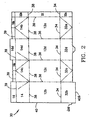
- FIG. 2 illustrates a blank 30 for the carton 10 not according to the invention of FIG. 1 .
- the side panels 12a-d are separated from bottom panels 32a-d by bottom horizontal score lines 34 and each of the side panels 12a-d and bottom panels 32a-d are separated from each other by vertical score lines 36.
- the side panels 12a-d are separated from top panels 14 and 14b-d by top horizontal score lines 38.
- the top fin panels 16 and 16b-d are separated from top panels 14 and 14b-d by upper horizontal score line 39.
- the sealing panel 22 is separated from side panel 12a by a vertical score line 36.
- a top sealing panel 22b and a bottom sealing panel 22c further define sealing panel 22.
- the raw paper edge 40 extends along top fin 16, top panel 14, side panel 12b and bottom panel 32b.
- the bottom of the carton 10 not according to the invention has the elevated portion 20 bounded by substantially planar portions 60 and 62.
- the planar portions 60 and 62 are substantially perpendicular to side panels 12a, 12b and 12c and 12d, not shown.
- the planar portions 60 and 62 contact the conveyor belt 54 while elevated portion 20 is elevated above the belt 54 and any moisture thereon. The same applies during distribution whether in a crate or a shelf at a store.
- the elevated portion 20 is further defined by angled portions 64 and 66 and elevated planar portion 70.
- the elevated planar portion 70 is further defined as elevated planar portion 70a and elevated planar portion 70b.
- the elevated planar portion 70a substantially includes a portion of panel 32b while elevated planar portion 70b includes a portion of panel 32d.
- the exposed raw paper edge 40a traverses the bottom of the carton 10, extending from the end of panel 12 a to the end of panel 12c, not shown.
- the elevated portion 20 traverses the bottom of the carton 10.
- elevated portion 20 is centered on the bottom of the carton 10 with planar portions 60 and 62 being equal in area to each other.
- planar portions 60 and 62 may be unequal and elevated portion 20 may be uncentered.
- elevated portion 70a, angled portion 64 and planar portion 60 all are part of bottom panel 32b. Also, elevated portion 70b, angled portion 66 and planar portion 62 all are part of bottom panel 32d.
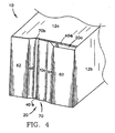
- FIG. 4 shows a first embodiment of the present invention.
- FIG. 4 is similar to FIG. 3 except that all exposed raw paper edges 40a and 40b are elevated.
- the exposed edge 40b is substantially perpendicular to exposed edge 40a.
- a second elevated portion 20a elevates this exposed edge 40a thereby preventing moisture absorption as with exposed edge 40b.
- the second elevated portion 20a has an angled portion 70 that engages planar portion 60, side panel 12a, and angled portion 64.
- the exposed raw edges may be elevated in a similar fashion.
- FIG. 5 A similar first embodiment of the present invention is illustrated in FIG. 5 .
- the exposed edge 40b is substantially perpendicular to exposed edge 40a.
- a side elevated portion 20a elevates this exposed edge 40a thereby preventing moisture absorption as with exposed edge 40b
- the side elevated portion 20a has an angled portion 72 which engages planar portion 60, side panel 12a, and angled portion 64.
- the exposed raw edges may be elevated in a similar fashion.
- the secondary elevated portion 100 prevents loss of elevation in the center of the bottom of the carton 10 during transportation from a packaging machine to the retailer/wholesaler to the consumer.
- the center of the bottom of the carton 10 is most susceptible to deelevation from the weight of the product.
- the weight of the product in the carton 10 is focused on the center of the bottom of the carton 10, and thus it is necessary to provide greater elevation in this area. This greater elevation is provided by the secondary elevated portion 100 which compensates for gravitational forces exerted by the product on the center of the bottom of the carton 10.
- the secondary elevated portion 100 is triangular in shape with its apex 101 near the exact center of the bottom of the carton 10.
- the secondary elevated portion 100 is substantially contained within elevated planar portions 70a and 70b. However, there is a transition to angled portion 66.
- the triangular shaped embodiment of the secondary elevated portion 100 may be rotated any degree from 1-360 degrees, about apex 101. Thus, the secondary elevated portion 100 may lie entirely within elevated planar portion 70a.
- the secondary elevated portion 100 is also partially defined by secondary angled portions 102, 104, 106 and 108.
- the secondary angled portions 102 and 104 form a transition from the secondary elevated portion 100 to elevated planar portion 70a whereas the secondary angled portions 106 and 108 form a transition from the secondary elevated portion 100 to elevated planar portion 70b.
- the bottom of the carton 10 is usually formed on a mandrel of a form, fill and seal packaging machine, not shown.
- the carton blanks 30 are fed from a magazine, not shown, to a bottom forming station of the machine, not shown. During the transfer from magazine to bottom forming station, the carton blank is erected. On the bottom forming station, the bottom panels are pretreated if necessary, and then heat-sealed together to form the bottom. This is accomplished by pressing against the bottom panels as they lie on the mandrel.
- a special press and mandrel that allows for the elevated bottom of the present invention.
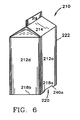
- a carton 210 not according to the invention is shown in FIG. 6 .
- the carton 210 has a plurality of side panels 212a and 212b, a top panel 214, a top fin 216, bottom score iines 218a and 218b defining the bottom from the side panels 212a and 212b, and an elevated portion 220.
- a sealing panel 222 is connected to the side panel 212a and is folded over and sealed to the side panel 212b, not shown.
- the folding and sealing of the carton creates a raw paperboard edge which extends from the top 216 to the bottom of the carton 210 along this intersection of the sealing panel 222 and side panel 212b, top panel 214, top fin 216 and the bottom panel corresponding to side panel 212d.
- FIG. 7 illustrates a blank 230 for the carton 210 not according to the invention of FIG. 6 .
- the side panels 212a-d are separated from bottom panels 232a-d by Bottom horizontal score lines 234 and each of the side panels 212a-d and bottom panels 232a-d are separated from each other by vertical score lines 236.
- the side panels 212a-d are separated from top panels 214a-d by top horizontal score lines 238.
- the top fin panels 216a-d are separated from top panels 214a-d by upper horizontal score line 239.
- the sealing panel 222 is separated from side panel 212a by a vertical score line 236.
- a top sealing panel 222b and a bottom sealing panel 222c further define sealing panel 222.
- the raw paperboard edge 240 extends along the entire perimeter of the carton blank 230. However, the most important portions of the raw paperboard edge 240 are portions 240a and 240b which lie on the bottom of the carton. All other portions of the raw paperboard edge 240 are either covered by a coated panel, or are elevated above the surface when the blank 230 is formed into a carton 210. Thus, moisture absorption by these portions of the raw paperboard edge 240 is highly unlikely.
- FIG. 8 shows the bottom of a carton of the kind shown in FIGs. 6 and 7 .
- the bottom of the carton 210 has the elevated portion 220 bounded by substantially planar portions 260 and 262.
- the planar portions 260 and 262 are substantially perpendicular to side panels 212a, 212b and 212c and 212d, not shown.
- the planar portions 260 and 262 contact a surface such as a conveyor belt on a packaging machine while the elevated portion 220 is elevated above the surface and any moisture thereon. The same applies during distribution of the carton whether in a crate or on a shelf at a store.
- the elevated portion 220 is further defined by angled portions 264 and 266 and elevated planar portion 270.
- the elevated planar portion 270 is further defined as elevated planar portion 270a and elevated planar portion 270b.
- the elevated planar portion 270a substantially includes a portion of panel 232b while elevated planar portion 270b includes a portion of panel 232d.
- the exposed raw paperboard edge 240b traverses the bottom of the carton 210, extending from the end of panel 212a to the end of panel 212c, not shown.
- the elevated portion 220 traverses the bottom of the carton 210.
- the elevated portion 220 is centered on the bottom of the carton 210 with planar portions 260 and 262 being equal in area to each other.
- planar portions 260 and 262 may be unequal and elevated portion 220 may be uncentered.
- the exposed edge 240a is substantially perpendicular to exposed edge 240b.
- a side elevated/angled portion 220a elevates this exposed edge 240a thereby preventing moisture absorption as with exposed edge 240b.
- the side elevated/angled portion 220a has an angled portion 272 which engages planar portion 260, side panel 212a, and angled portion 264. Those skilled in the art will recognize that the exposed raw edges may be elevated in a similar fashion.
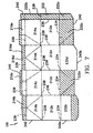
- FIG. 9 A similar second embodiment of the bottom of a carton of the present invention is shown in FIG. 9 .
- the carton 210 of FIG. 9 is similar to the carton 210 of FIG. 8 except that approximately in the center of the elevated portion 220 are secondary elevated portions 300 and 301.
- the secondary elevated portions 300 and 301 prevent loss of elevation in the center of the bottom of the carton 210 during transportation from a packaging machine to the retailer/wholesaler to the consumer.
- the center of the bottom of the carton 210 is most susceptible to deelevation from the weight of the product.
- the weight of the product in the carton 210 is focused on the center of the bottom of the carton 210, and thus it is necessary to provide greater elevation in this area. This greater elevation is provided by the secondary elevated portions 300 and 301 which compensate for gravitational forces exerted by the product on the center of the bottom of the carton 210.
- the secondary elevated portions 300 and 301 are triangular in shape with apices 302a-b facing the center of the bottom of the carton 210.
- the secondary elevated potions 300 and 301 are substantially contained within elevated planar portions 270a and 270b. However, there is a transition for each secondary elevated portions 300 and 301 to angled portions 266 and 264, respectively.
- the triangular shaped embodiment of the secondary elevated portions 300 and 301 may be rotated any degree from 1-360 degrees, about apices 302a-b. Thus the secondary elevated portions 300 and 301 may lie entirely within elevated planar portion 270b and 270a, respectively.
- the secondary elevated portions 300 and 301 are partially defined by secondary angled portions 304a-d.
- the secondary angled portions 304a-d form a transition from the secondary elevated portions 300 and 301 to the elevated planar portions 270b and 270a.
- the carton 210 of FIG. 9 may only have one secondary elevated portion 300 or 301 which may be disposed on either of planar portion 270a or 270b.
- the bottom of the carton 210 is usually formed on a mandrel of a form, fill and seal packaging machine, not shown.
- the carton blanks 230 are fed from a magazine, not shown, to a bottom forming station of the machine, not shown. During the transfer from magazine to bottom forming station, the carton blank is erected. On the bottom forming station, the bottom panels are pretreated if necessary, and then heat sealed together to form the bottom. This is accomplished by pressing against the bottom panels as they lie on the mandrel.
- a special sealing plate and mandrel which allows for the elevated bottom of the present invention.
Landscapes
- Engineering & Computer Science (AREA)
- Mechanical Engineering (AREA)
- Cartons (AREA)
- Packaging Frangible Articles (AREA)
- Laminated Bodies (AREA)
Abstract
Description
- The present invention relates to a carton having an elevated bottom. Specifically, the present invention relates to a carton having the edge portions of the bottom elevated to protect the raw paperboard edges from damage and absorption of moisture.
- Cartons fabricated from a carton blank on a form, fill and seal packaging machine risk absorption of moisture into the raw paperboard edges of the bottom of the carton. This absorption is accelerated if the raw paperboard edges are damaged and the carton is continuously exposed to moisture. The transportation, loading and storage of the carton from the conveyance between the packaging machine/packer unit and the retailer display are all sources for damage and moisture absorption.
- The raw paper edges are a by-product of the composition of the carton blank. Generally, the carton blank is cut and scored from a sheet of coated fiberboard material. The coated fiberboard material is usually composed of three layers, and may have a barrier layer juxtaposed between fiberboard layers. The exposed surfaces of this sheet are coated with a polymer material such as polyethylene. However, the coating does not extend to the edges which are thus left uncoated, and partially unprotected at least to moisture and sensitive to damage. When the carton is erected and partially formed, these raw paper edges are most prevalent at the bottom of the carton. If moisture is absorbed into the raw paper edges, the water may be absorbed throughout the fibreboard interior layer, which due to its cellulose-like nature, has a strong affinity for liquids. This absorption of moisture may compromise the integrity of the carton thereby rendering it defective.
- This problem has yet to be directly addressed by the packaging industry. However, inventions directed to resolving the stability of cartons have been disclosed in the prior art.
U.S. Patent Nos. 5,482,204 , and5,588,943 , respectively for a Carton Bottom Sealer and Carton Bottom Sealing Dies disclose cartons having an embossed inverse pyramidal bottom which is directed to providing greater stability to the filled carton and to reduce bulging of the carton. It should be noted, as shown inFIGS. 8 and9 of these Patents, that the end portions of the exposed raw paper edges of the bottom of the carton are not embossed, and therefore are susceptible to moisture absorption. -
U.S. Patent No. 5,222,667 , for a Container Made of Paper-Base Laminate, similarly discloses a carton having an inverted V-shaped bottom to provide greater stability to the carton. As shown inFIG. 6 of the Patent, the raw paper edge of panel 27 is not inverted and is susceptible to moisture absorption since the V-shaped inversion begins at the raw paper edge and since the inversion must be centered to provide stability to the carton. - Reference is also directed to
US Patent No. 3,586,232 which discloses a paperboard carton formed from a scored blank. Its bottom closure has overlapped and adhesively secured flaps, and is shaped to provide two opposing ridges with a recessed portion therebetween. - The present invention is directed at a carton having a plurality of side panels and a plurality of bottom panels corresponding thereto, the plurality of bottom panels folded and sealed together to form a sealed base, the last folded and sealed bottom panel having an end exposed edge traversing the base of the carton. The base comprises a primary elevated portion inverted into the carton and extending along the length of the end exposed edge and first and second substantially planar portions of the bottom panels respectively on either side of the elevated portion and extending to the ends of the side panels corresponding thereto, each portion being substantially perpendicular to the corresponding side panel.
- According to a first aspect of the invention the last folded and sealed bottom panel has a side exposed edge substantially perpendicular to the end exposed edge. The side exposed edge is elevated relative to its adjacent substantially planar portion by means of a side elevated portion extending the length of the side exposed edge between the primary elevated portion and the respective side panel.
- According to a second aspect of the invention the penultimate folded and sealed bottom panel has a side exposed edge substantially perpendicular to the end exposed edge. The side exposed edge is elevated relative to its adjacent substantially planar portion by means of a side elevated portion extending the length of the side exposed edge between the primary elevated portion and the respective side panel.
- The primary elevated portion in a carton of the invention will normally comprise a planar section. It is also preferred, but not essential, that the substantially planar portions are substantially equal in area. Neither is it essential that the end exposed edge is at the centre of the primary elevated portion.
- The present invention offers a solution to the problem of absorption of moisture through raw paper edges by providing a carton having the raw paper edges elevated in order to protect the raw paperboard edges and reduce the susceptibility of moisture absorption. This is accomplished without adversely affecting the carton.
- The invention and embodiments thereof will now be described by way of example and with reference to the accompanying drawings. In the drawings:
-
FIG. 1 is a perspective view of a carton according to the state of the art ; -
FIG. 2 is a plan view of a blank for the carton according to the state of the art ofFIG. 1 ; -
FIG. 3 is a bottom perspective view of the carton according to the state of the art ofFIG. 1 ; -
FIG. 4 is a bottom perspective view of the bottom of a carton according to a first embodiment of the present invention; -
FIG. 5 is a bottom perspective view of the bottom of another carton according to the first embodiment of the present invention; -
FIG. 6 is a perspective view of a carton according to the state of the art ; -
FIG. 7 is a plan view of a blank for the carton according to the state of the art ofFIG. 6 ; -
FIG. 8 is a bottom perspective view of the carton according to a second embodiment of the present invention ; and -
FIG. 9 is a bottom perspective view of the bottom of another carton according to the second embodiment of the present invention. - The
carton 10 not according to the invention inFIG. 1 has a plurality ofside panels top panel 14, atop fin 16,bottom score lines 18a and 18b defining the bottom from theside panels portion 20. Theside panel 12b is actually folded over and sealed to asealing panel 22. The folding and sealing of the carton creates a raw paper edge which extends from thetop 16 to the bottom of thecarton 10 along this intersection of thesealing panel 22 andside panel 12b,top panel 14,top fin 16 and the bottom panel corresponding toside panel 12b. -
FIG. 2 illustrates a blank 30 for thecarton 10 not according to the invention ofFIG. 1 . Theside panels 12a-d are separated frombottom panels 32a-d by bottomhorizontal score lines 34 and each of theside panels 12a-d andbottom panels 32a-d are separated from each other byvertical score lines 36. Theside panels 12a-d are separated fromtop panels horizontal score lines 38. Thetop fin panels top panels horizontal score line 39. Thesealing panel 22 is separated fromside panel 12a by avertical score line 36. Atop sealing panel 22b and abottom sealing panel 22c further definesealing panel 22. Theraw paper edge 40 extends alongtop fin 16,top panel 14,side panel 12b andbottom panel 32b. - As shown in
FIG. 3 , the bottom of thecarton 10 not according to the invention has theelevated portion 20 bounded by substantiallyplanar portions planar portions side panels planar portions portion 20 is elevated above the belt 54 and any moisture thereon. The same applies during distribution whether in a crate or a shelf at a store. - The elevated
portion 20 is further defined byangled portions planar portion 70. The elevatedplanar portion 70 is further defined as elevatedplanar portion 70a and elevatedplanar portion 70b. The elevatedplanar portion 70a substantially includes a portion ofpanel 32b while elevatedplanar portion 70b includes a portion ofpanel 32d. The exposed raw paper edge 40a traverses the bottom of thecarton 10, extending from the end ofpanel 12 a to the end ofpanel 12c, not shown. Likewise, theelevated portion 20 traverses the bottom of thecarton 10. Preferably, elevatedportion 20 is centered on the bottom of thecarton 10 withplanar portions planar portions portion 20 may be uncentered. - It is readily apparent that elevated
portion 70a,angled portion 64 andplanar portion 60 all are part ofbottom panel 32b. Also,elevated portion 70b,angled portion 66 andplanar portion 62 all are part ofbottom panel 32d. -
FIG. 4 shows a first embodiment of the present invention.FIG. 4 is similar toFIG. 3 except that all exposedraw paper edges 40a and 40b are elevated. The exposededge 40b is substantially perpendicular to exposed edge 40a. A secondelevated portion 20a elevates this exposed edge 40a thereby preventing moisture absorption as with exposededge 40b. The secondelevated portion 20a has an angledportion 70 that engagesplanar portion 60,side panel 12a, andangled portion 64. Those skilled in the art will recognize that the exposed raw edges may be elevated in a similar fashion. - A similar first embodiment of the present invention is illustrated in
FIG. 5 . As shown inFIG. 5 , the exposededge 40b is substantially perpendicular to exposed edge 40a. A sideelevated portion 20a elevates this exposed edge 40a thereby preventing moisture absorption as with exposededge 40b The side elevatedportion 20a has an angledportion 72 which engagesplanar portion 60,side panel 12a, andangled portion 64. Those skilled in the art will recognize that the exposed raw edges may be elevated in a similar fashion. - Approximately in the center of the
elevated portion 20 is a secondaryelevated portion 100. The secondaryelevated portion 100 prevents loss of elevation in the center of the bottom of thecarton 10 during transportation from a packaging machine to the retailer/wholesaler to the consumer. As is apparent, the center of the bottom of thecarton 10 is most susceptible to deelevation from the weight of the product. The weight of the product in thecarton 10 is focused on the center of the bottom of thecarton 10, and thus it is necessary to provide greater elevation in this area. This greater elevation is provided by the secondaryelevated portion 100 which compensates for gravitational forces exerted by the product on the center of the bottom of thecarton 10. - As shown in
FIG. 5 , the secondaryelevated portion 100 is triangular in shape with itsapex 101 near the exact center of the bottom of thecarton 10. The secondaryelevated portion 100 is substantially contained within elevatedplanar portions angled portion 66. Alternatively, the triangular shaped embodiment of the secondaryelevated portion 100 may be rotated any degree from 1-360 degrees, aboutapex 101. Thus, the secondaryelevated portion 100 may lie entirely within elevatedplanar portion 70a. - The secondary
elevated portion 100 is also partially defined by secondaryangled portions angled portions elevated portion 100 to elevatedplanar portion 70a whereas the secondaryangled portions 106 and 108 form a transition from the secondaryelevated portion 100 to elevatedplanar portion 70b. - The bottom of the
carton 10 is usually formed on a mandrel of a form, fill and seal packaging machine, not shown. Thecarton blanks 30 are fed from a magazine, not shown, to a bottom forming station of the machine, not shown. During the transfer from magazine to bottom forming station, the carton blank is erected. On the bottom forming station, the bottom panels are pretreated if necessary, and then heat-sealed together to form the bottom. This is accomplished by pressing against the bottom panels as they lie on the mandrel. In order to achieve the elevated bottom of the present invention, one may have a special press and mandrel that allows for the elevated bottom of the present invention. - A
carton 210 not according to the invention is shown inFIG. 6 . Thecarton 210 has a plurality ofside panels top panel 214, atop fin 216, bottom score iines 218a and 218b defining the bottom from theside panels elevated portion 220. A sealingpanel 222, partially shown inFIG. 6 , is connected to theside panel 212a and is folded over and sealed to theside panel 212b, not shown. The folding and sealing of the carton creates a raw paperboard edge which extends from the top 216 to the bottom of thecarton 210 along this intersection of the sealingpanel 222 andside panel 212b,top panel 214,top fin 216 and the bottom panel corresponding toside panel 212d. -
FIG. 7 illustrates a blank 230 for thecarton 210 not according to the invention ofFIG. 6 . Theside panels 212a-d are separated frombottom panels 232a-d by Bottomhorizontal score lines 234 and each of theside panels 212a-d andbottom panels 232a-d are separated from each other by vertical score lines 236. Theside panels 212a-d are separated fromtop panels 214a-d by top horizontal score lines 238. Thetop fin panels 216a-d are separated fromtop panels 214a-d by upperhorizontal score line 239. The sealingpanel 222 is separated fromside panel 212a by avertical score line 236. Atop sealing panel 222b and abottom sealing panel 222c further define sealingpanel 222. Theraw paperboard edge 240 extends along the entire perimeter of the carton blank 230. However, the most important portions of theraw paperboard edge 240 areportions raw paperboard edge 240 are either covered by a coated panel, or are elevated above the surface when the blank 230 is formed into acarton 210. Thus, moisture absorption by these portions of theraw paperboard edge 240 is highly unlikely. -
FIG. 8 shows the bottom of a carton of the kind shown inFIGs. 6 and7 . The bottom of thecarton 210 has theelevated portion 220 bounded by substantiallyplanar portions planar portions side panels planar portions elevated portion 220 is elevated above the surface and any moisture thereon. The same applies during distribution of the carton whether in a crate or on a shelf at a store. - The
elevated portion 220 is further defined byangled portions planar portion 270. The elevatedplanar portion 270 is further defined as elevatedplanar portion 270a and elevatedplanar portion 270b. The elevatedplanar portion 270a substantially includes a portion ofpanel 232b while elevatedplanar portion 270b includes a portion ofpanel 232d. The exposedraw paperboard edge 240b traverses the bottom of thecarton 210, extending from the end ofpanel 212a to the end ofpanel 212c, not shown. Likewise, theelevated portion 220 traverses the bottom of thecarton 210. Preferably, theelevated portion 220 is centered on the bottom of thecarton 210 withplanar portions planar portions elevated portion 220 may be uncentered. - It is readily apparent that
elevated portion 270a.angled portion 264 andplanar portion 260 all are part ofbottom panel 232b. Also,elevated portion 270b,angled portion 266 andplanar portion 262 all are part ofbottom panel 232d. - The exposed
edge 240a is substantially perpendicular to exposededge 240b. A side elevated/angled portion 220a elevates this exposededge 240a thereby preventing moisture absorption as with exposededge 240b. The side elevated/angled portion 220a has an angledportion 272 which engagesplanar portion 260,side panel 212a, andangled portion 264. Those skilled in the art will recognize that the exposed raw edges may be elevated in a similar fashion. - A similar second embodiment of the bottom of a carton of the present invention is shown in
FIG. 9 . Thecarton 210 ofFIG. 9 is similar to thecarton 210 ofFIG. 8 except that approximately in the center of theelevated portion 220 are secondaryelevated portions elevated portions carton 210 during transportation from a packaging machine to the retailer/wholesaler to the consumer. As is apparent, the center of the bottom of thecarton 210 is most susceptible to deelevation from the weight of the product. The weight of the product in thecarton 210 is focused on the center of the bottom of thecarton 210, and thus it is necessary to provide greater elevation in this area. This greater elevation is provided by the secondaryelevated portions carton 210. - In an exemplary embodiment, the secondary
elevated portions carton 210. The secondaryelevated potions planar portions elevated portions angled portions elevated portions elevated portions planar portion - In this embodiment, the secondary
elevated portions angled portions 304a-d. The secondaryangled portions 304a-d form a transition from the secondaryelevated portions planar portions - In an alternative embodiment not shown, the
carton 210 ofFIG. 9 may only have one secondaryelevated portion planar portion - The bottom of the
carton 210 is usually formed on a mandrel of a form, fill and seal packaging machine, not shown. The carton blanks 230 are fed from a magazine, not shown, to a bottom forming station of the machine, not shown. During the transfer from magazine to bottom forming station, the carton blank is erected. On the bottom forming station, the bottom panels are pretreated if necessary, and then heat sealed together to form the bottom. This is accomplished by pressing against the bottom panels as they lie on the mandrel. In order to achieve the elevated bottom of the present invention, one may have a special sealing plate and mandrel which allows for the elevated bottom of the present invention.
Claims (6)
- A carton (10) having a plurality of side panels (12) and a plurality of bottom panels (32) corresponding thereto, the plurality of bottom panels folded and sealed together to form a sealed base, the last folded and sealed bottom panel (32b) having an end exposed edge (40b) traversing the base of the carton, which base comprises:a primary elevated portion (20) inverted into the carton (10) and extending along the length of the end exposed edge (40b); andfirst and second substantially planar portions (60,62) of the bottom panels (32) respectively on either side of the elevated portion (20) and extending to the ends of the side panels (12) corresponding thereto, each portion being substantially perpendicular to the corresponding side panel,CHARACTERISED IN THATthe last folded and sealed bottom panel (32b) has a side exposed edge (40a) substantially perpendicular to the end exposed edge (40b) which side exposed edge (40a) is elevated relative to its adjacent substantially planar portion (60) by means of a side elevated portion (20a) extending the length of the side exposed edge (40a) between the primary elevated portion (20) and the respective side panel (12b).
- A carton (210) having a plurality of side panels (212) and a plurality of bottom panels (232) corresponding thereto, the plurality of bottom panels folded and sealed together to form a sealed base, the last folded and sealed bottom panel (232d) having an end exposed edge (240b) traversing the base of the carton, which base comprises:a primary elevated portion (220) inverted into the carton (210) and extending along the length of the end exposed edge (240b);first and second substantially planar portions (260,262) of the bottom panels (232) respectively on either side of the elevated portion (220) and extending to the ends of the side panels (212) corresponding thereto, each portion being substantially perpendicular to the corresponding side panel,CHARACTERISED IN THATthe penultimate folded and sealed bottom panel (232b) has a side exposed edge (240a) substantially perpendicular to the end exposed edge (240b) which side exposed edge (240a) is elevated relative to its adjacent substantially planar portion (260) by means of a side elevated portion (220a) extending the length of the side exposed edge (240a) between the primary elevated portion (220) and the respective side panel (212b).
- A carton according to Claim 1 or Claim 2 wherein the base has first and second angled portions (64,66,264,266) extending from either side of the primary elevated portion (20,220) to the respective substantially planar portion (60,62,260,262).
- A carton according to any preceding Claim wherein the primary elevated portion (20,220) comprises a planar section.
- A carton according to any preceding Claim wherein the first and second substantially planar portions (60,62,260,262) are substantially equal in area.
- A carton according to any preceding Claim wherein the exposed end edge (40a,240b) is not at the centre of the primary elevated portion (20,220).
Applications Claiming Priority (7)
| Application Number | Priority Date | Filing Date | Title |
|---|---|---|---|
| US955063 | 1978-10-26 | ||
| US128748 | 1987-12-04 | ||
| US08/955,063 US5845840A (en) | 1997-10-21 | 1997-10-21 | Elevated bottom carton |
| US52401 | 1998-03-31 | ||
| US09/052,401 US5988490A (en) | 1997-10-21 | 1998-03-31 | Elevated bottom carton |
| US09/128,748 US6027015A (en) | 1997-10-21 | 1998-08-04 | Elevated bottom carton |
| EP98953694A EP0999983B1 (en) | 1997-10-21 | 1998-10-19 | Elevated bottom carton |
Related Parent Applications (2)
| Application Number | Title | Priority Date | Filing Date |
|---|---|---|---|
| EP98953694.1 Division | 1998-10-19 | ||
| EP98953694A Division EP0999983B1 (en) | 1997-10-21 | 1998-10-19 | Elevated bottom carton |
Publications (2)
| Publication Number | Publication Date |
|---|---|
| EP1535848A1 EP1535848A1 (en) | 2005-06-01 |
| EP1535848B1 true EP1535848B1 (en) | 2012-02-22 |
Family
ID=25496326
Family Applications (1)
| Application Number | Title | Priority Date | Filing Date |
|---|---|---|---|
| EP05075321A Expired - Lifetime EP1535848B1 (en) | 1997-10-21 | 1998-10-19 | Elevated bottom carton |
Country Status (7)
| Country | Link |
|---|---|
| US (2) | US5845840A (en) |
| EP (1) | EP1535848B1 (en) |
| AT (1) | ATE546370T1 (en) |
| DK (1) | DK1535848T3 (en) |
| ES (1) | ES2386167T3 (en) |
| RU (1) | RU2187447C2 (en) |
| TW (1) | TW360609B (en) |
Families Citing this family (8)
| Publication number | Priority date | Publication date | Assignee | Title |
|---|---|---|---|---|
| US6739499B1 (en) * | 1997-06-11 | 2004-05-25 | Nimco Corporation | Method and apparatus for forming a stable container bottom |
| US5845840A (en) * | 1997-10-21 | 1998-12-08 | Tetra Laval Holdings & Finance, S.A. | Elevated bottom carton |
| US6094884A (en) * | 1997-10-21 | 2000-08-01 | Tetra Laval Holdings & Finance, Sa | Forming apparatus for an elevated bottom carton |
| US6328204B1 (en) | 2000-07-26 | 2001-12-11 | Tetra Laval Holdings & Finance, Sa | Carton with over-folded bottom |
| US6644539B2 (en) * | 2001-10-12 | 2003-11-11 | Tetra Laval Holdings & Finance, Sa | Package with bottom panel stand-offs |
| RU2407681C2 (en) * | 2005-01-29 | 2010-12-27 | Элопак Системc Аг | Container, preform, mandrel and method of producing container |
| JP5352876B2 (en) * | 2007-07-12 | 2013-11-27 | イマジニアリング株式会社 | Ignition / chemical reaction promotion / flame holding device, speed internal combustion engine, and furnace |
| JP6194196B2 (en) * | 2013-06-29 | 2017-09-06 | 日本テトラパック株式会社 | Packaging and filling equipment, paper containers and blanks |
Family Cites Families (33)
| Publication number | Priority date | Publication date | Assignee | Title |
|---|---|---|---|---|
| US1414236A (en) * | 1921-02-25 | 1922-04-25 | Walmsley William Edward | Collapsible box |
| US2142142A (en) * | 1936-08-03 | 1939-01-03 | Kitchener K Newsom | Container |
| US2523251A (en) * | 1949-08-17 | 1950-09-19 | Nat Folding Box Company Inc | Round cornered folding box |
| US2815164A (en) * | 1955-10-21 | 1957-12-03 | Claude D Painter | Popcorn box |
| US3236436A (en) * | 1963-06-27 | 1966-02-22 | Reynolds Metals Co | Gusseted corner carton |
| US3275216A (en) * | 1964-06-01 | 1966-09-27 | Olin Mathieson | Container |
| GB1075720A (en) * | 1964-12-02 | 1967-07-12 | Esseltepack Ab | A method of sealing cartons and cartons thus sealed |
| US3412922A (en) * | 1966-09-06 | 1968-11-26 | Ex Cell O Corp | Paperboard container closure |
| US3402876A (en) * | 1967-04-10 | 1968-09-24 | American Can Co | Easy open carton construction and blank therefor |
| US3586232A (en) * | 1969-02-06 | 1971-06-22 | Pneumatic Scale Corp | Carton |
| US3908890A (en) * | 1972-04-14 | 1975-09-30 | Kliklok Corp | Heat sealable carton and method of forming same |
| EP0010422A1 (en) * | 1978-10-13 | 1980-04-30 | Novus Corp. N.V. | Carton and method of producing carton blanks therefor |
| US4221162A (en) * | 1979-01-19 | 1980-09-09 | Ex-Cell-O Corporation | Carton bottom tucking and tacking apparatus for packaging machines |
| US4313556A (en) * | 1980-10-14 | 1982-02-02 | Champion International Corporation | Carton having foldable bottom and carton blank |
| NO152086B (en) * | 1982-12-22 | 1985-04-22 | Elopak As | SUBJECT FOR TANK WITH WASH PROTECTED EDGE IN THE BOTTOM |
| US4601425A (en) * | 1984-02-29 | 1986-07-22 | Nimco Corporation | Nonwicking bottom closure for a liquid-tight container |
| US4589862A (en) * | 1985-07-08 | 1986-05-20 | Ex-Cell-O Corporation | Apparatus for folding and tucking a container closure |
| SE457874B (en) * | 1986-04-18 | 1989-02-06 | Tetra Pak Ab | DEVICE FOR PACKAGING MACHINE |
| JPS6317007U (en) * | 1986-07-15 | 1988-02-04 | ||
| JPS63141108U (en) * | 1987-03-04 | 1988-09-16 | ||
| GB8901319D0 (en) * | 1989-01-21 | 1989-03-15 | Elopak Systems | Packaging |
| US4990128A (en) * | 1989-09-11 | 1991-02-05 | Elopak Systems A.G. | Carton end panel folding mechanism |
| JP2813820B2 (en) * | 1989-09-13 | 1998-10-22 | 四国化工機株式会社 | Container molding equipment |
| GB9012333D0 (en) * | 1990-06-02 | 1990-07-25 | Elopak Systems | Packaging |
| US5234398A (en) * | 1990-06-02 | 1993-08-10 | Elopak Systems Ag | Method and apparatus for folding end closure panels |
| JP3002753B2 (en) * | 1991-02-05 | 2000-01-24 | 四国化工機株式会社 | Paper-based laminate container and bottom crimping device therefor |
| US5152736A (en) * | 1991-10-28 | 1992-10-06 | Elopak Systems A.G. | Concave shaped container bottom end closure and method of forming same |
| US5265794A (en) * | 1992-01-10 | 1993-11-30 | Rexham Corporation | Tamper evident folding carton |
| US5232146A (en) * | 1992-08-19 | 1993-08-03 | Tino Antonacci | Box and blank therefor |
| US5482204A (en) | 1994-03-21 | 1996-01-09 | International Paper Company | Carton bottom sealer |
| US5725144A (en) * | 1996-06-26 | 1998-03-10 | Tenneco Packaging | Collapsible paperboard carton |
| US5762595A (en) * | 1996-10-01 | 1998-06-09 | Elopak Systems Ag | Flat-sitting container bottom end closure and mechanism for forming same |
| US5845840A (en) * | 1997-10-21 | 1998-12-08 | Tetra Laval Holdings & Finance, S.A. | Elevated bottom carton |
-
1997
- 1997-10-21 US US08/955,063 patent/US5845840A/en not_active Expired - Lifetime
-
1998
- 1998-03-31 US US09/052,401 patent/US5988490A/en not_active Expired - Lifetime
- 1998-09-05 TW TW087114754A patent/TW360609B/en not_active IP Right Cessation
- 1998-10-19 AT AT05075321T patent/ATE546370T1/en active
- 1998-10-19 ES ES05075321T patent/ES2386167T3/en not_active Expired - Lifetime
- 1998-10-19 RU RU2000112529/13A patent/RU2187447C2/en not_active IP Right Cessation
- 1998-10-19 DK DK05075321.9T patent/DK1535848T3/en active
- 1998-10-19 EP EP05075321A patent/EP1535848B1/en not_active Expired - Lifetime
Also Published As
| Publication number | Publication date |
|---|---|
| DK1535848T3 (en) | 2012-05-21 |
| US5845840A (en) | 1998-12-08 |
| EP1535848A1 (en) | 2005-06-01 |
| RU2187447C2 (en) | 2002-08-20 |
| ES2386167T3 (en) | 2012-08-10 |
| US5988490A (en) | 1999-11-23 |
| TW360609B (en) | 1999-06-11 |
| ATE546370T1 (en) | 2012-03-15 |
Similar Documents
| Publication | Publication Date | Title |
|---|---|---|
| EP1368233B1 (en) | Carton, blank, methods and apparatus for making a carton | |
| KR20000064741A (en) | Blanks for Packaging and Packaging | |
| WO2006137985A2 (en) | Methods and systems for packaging a product | |
| EP0735950B1 (en) | Gable top carton having a u-shaped stake seal and and apparatus for forming same | |
| RU2407681C2 (en) | Container, preform, mandrel and method of producing container | |
| AU2002237880A1 (en) | Carton, blank, methods and apparatus for making a carton | |
| US6027015A (en) | Elevated bottom carton | |
| EP1535848B1 (en) | Elevated bottom carton | |
| TW202248092A (en) | Article carrier and blank therefor | |
| EP0999983B1 (en) | Elevated bottom carton | |
| EP0876962B1 (en) | Packaging container made of a carton blank | |
| CA2694310A1 (en) | Container with reclosable pour spout | |
| EP1064146B1 (en) | A forming apparatus for an elevated bottom carton | |
| US11505360B2 (en) | Leak proof container with adhesive attachment | |
| EP0277517B1 (en) | A blank having folding lines for forming a container | |
| RU2200665C2 (en) | Apparatus for forming raised bottom carton | |
| MXPA00003426A (en) | Elevated bottom carton | |
| IL263588A (en) | Install anvil | |
| TW202120391A (en) | Carton and blank therefor | |
| JPS61287530A (en) | Flat top end cover for liquid vessel | |
| AU5360899A (en) | Packaging | |
| AU2123399A (en) | Minimal shipping container and method of construction |
Legal Events
| Date | Code | Title | Description |
|---|---|---|---|
| PUAI | Public reference made under article 153(3) epc to a published international application that has entered the european phase |
Free format text: ORIGINAL CODE: 0009012 |
|
| 17P | Request for examination filed |
Effective date: 20050209 |
|
| AC | Divisional application: reference to earlier application |
Ref document number: 0999983 Country of ref document: EP Kind code of ref document: P |
|
| AK | Designated contracting states |
Kind code of ref document: A1 Designated state(s): AT BE CH CY DE DK ES FI FR GB GR IE IT LI LU MC NL PT SE |
|
| AKX | Designation fees paid |
Designated state(s): AT BE CH CY DE DK ES FI FR GB GR IE IT LI LU MC NL PT SE |
|
| 17Q | First examination report despatched |
Effective date: 20080925 |
|
| GRAP | Despatch of communication of intention to grant a patent |
Free format text: ORIGINAL CODE: EPIDOSNIGR1 |
|
| GRAS | Grant fee paid |
Free format text: ORIGINAL CODE: EPIDOSNIGR3 |
|
| GRAA | (expected) grant |
Free format text: ORIGINAL CODE: 0009210 |
|
| AC | Divisional application: reference to earlier application |
Ref document number: 0999983 Country of ref document: EP Kind code of ref document: P |
|
| AK | Designated contracting states |
Kind code of ref document: B1 Designated state(s): AT BE CH CY DE DK ES FI FR GB GR IE IT LI LU MC NL PT SE |
|
| REG | Reference to a national code |
Ref country code: GB Ref legal event code: FG4D |
|
| REG | Reference to a national code |
Ref country code: CH Ref legal event code: EP |
|
| REG | Reference to a national code |
Ref country code: AT Ref legal event code: REF Ref document number: 546370 Country of ref document: AT Kind code of ref document: T Effective date: 20120315 |
|
| REG | Reference to a national code |
Ref country code: IE Ref legal event code: FG4D |
|
| RAP2 | Party data changed (patent owner data changed or rights of a patent transferred) |
Owner name: TETRA LAVAL HOLDINGS & FINANCE S.A. |
|
| REG | Reference to a national code |
Ref country code: DE Ref legal event code: R096 Ref document number: 69842609 Country of ref document: DE Effective date: 20120419 |
|
| REG | Reference to a national code |
Ref country code: NL Ref legal event code: T3 |
|
| REG | Reference to a national code |
Ref country code: DK Ref legal event code: T3 |
|
| REG | Reference to a national code |
Ref country code: SE Ref legal event code: TRGR |
|
| REG | Reference to a national code |
Ref country code: ES Ref legal event code: FG2A Ref document number: 2386167 Country of ref document: ES Kind code of ref document: T3 Effective date: 20120810 |
|
| PG25 | Lapsed in a contracting state [announced via postgrant information from national office to epo] |
Ref country code: BE Free format text: LAPSE BECAUSE OF FAILURE TO SUBMIT A TRANSLATION OF THE DESCRIPTION OR TO PAY THE FEE WITHIN THE PRESCRIBED TIME-LIMIT Effective date: 20120222 Ref country code: PT Free format text: LAPSE BECAUSE OF FAILURE TO SUBMIT A TRANSLATION OF THE DESCRIPTION OR TO PAY THE FEE WITHIN THE PRESCRIBED TIME-LIMIT Effective date: 20120622 Ref country code: FI Free format text: LAPSE BECAUSE OF FAILURE TO SUBMIT A TRANSLATION OF THE DESCRIPTION OR TO PAY THE FEE WITHIN THE PRESCRIBED TIME-LIMIT Effective date: 20120222 Ref country code: GR Free format text: LAPSE BECAUSE OF FAILURE TO SUBMIT A TRANSLATION OF THE DESCRIPTION OR TO PAY THE FEE WITHIN THE PRESCRIBED TIME-LIMIT Effective date: 20120523 |
|
| REG | Reference to a national code |
Ref country code: AT Ref legal event code: MK05 Ref document number: 546370 Country of ref document: AT Kind code of ref document: T Effective date: 20120222 |
|
| PG25 | Lapsed in a contracting state [announced via postgrant information from national office to epo] |
Ref country code: CY Free format text: LAPSE BECAUSE OF FAILURE TO SUBMIT A TRANSLATION OF THE DESCRIPTION OR TO PAY THE FEE WITHIN THE PRESCRIBED TIME-LIMIT Effective date: 20120222 |
|
| PLBE | No opposition filed within time limit |
Free format text: ORIGINAL CODE: 0009261 |
|
| STAA | Information on the status of an ep patent application or granted ep patent |
Free format text: STATUS: NO OPPOSITION FILED WITHIN TIME LIMIT |
|
| 26N | No opposition filed |
Effective date: 20121123 |
|
| PG25 | Lapsed in a contracting state [announced via postgrant information from national office to epo] |
Ref country code: AT Free format text: LAPSE BECAUSE OF FAILURE TO SUBMIT A TRANSLATION OF THE DESCRIPTION OR TO PAY THE FEE WITHIN THE PRESCRIBED TIME-LIMIT Effective date: 20120222 |
|
| REG | Reference to a national code |
Ref country code: DE Ref legal event code: R097 Ref document number: 69842609 Country of ref document: DE Effective date: 20121123 |
|
| PG25 | Lapsed in a contracting state [announced via postgrant information from national office to epo] |
Ref country code: MC Free format text: LAPSE BECAUSE OF NON-PAYMENT OF DUE FEES Effective date: 20121031 |
|
| REG | Reference to a national code |
Ref country code: CH Ref legal event code: PL |
|
| REG | Reference to a national code |
Ref country code: IE Ref legal event code: MM4A |
|
| REG | Reference to a national code |
Ref country code: FR Ref legal event code: ST Effective date: 20130628 |
|
| PG25 | Lapsed in a contracting state [announced via postgrant information from national office to epo] |
Ref country code: IE Free format text: LAPSE BECAUSE OF NON-PAYMENT OF DUE FEES Effective date: 20121019 Ref country code: CH Free format text: LAPSE BECAUSE OF NON-PAYMENT OF DUE FEES Effective date: 20121031 Ref country code: LI Free format text: LAPSE BECAUSE OF NON-PAYMENT OF DUE FEES Effective date: 20121031 |
|
| PG25 | Lapsed in a contracting state [announced via postgrant information from national office to epo] |
Ref country code: FR Free format text: LAPSE BECAUSE OF NON-PAYMENT OF DUE FEES Effective date: 20121031 |
|
| PG25 | Lapsed in a contracting state [announced via postgrant information from national office to epo] |
Ref country code: LU Free format text: LAPSE BECAUSE OF NON-PAYMENT OF DUE FEES Effective date: 20121019 |
|
| PGFP | Annual fee paid to national office [announced via postgrant information from national office to epo] |
Ref country code: ES Payment date: 20160913 Year of fee payment: 19 |
|
| PGFP | Annual fee paid to national office [announced via postgrant information from national office to epo] |
Ref country code: DE Payment date: 20161011 Year of fee payment: 19 Ref country code: GB Payment date: 20161019 Year of fee payment: 19 Ref country code: DK Payment date: 20161012 Year of fee payment: 19 Ref country code: NL Payment date: 20161010 Year of fee payment: 19 |
|
| PGFP | Annual fee paid to national office [announced via postgrant information from national office to epo] |
Ref country code: IT Payment date: 20161024 Year of fee payment: 19 Ref country code: SE Payment date: 20161011 Year of fee payment: 19 |
|
| REG | Reference to a national code |
Ref country code: DE Ref legal event code: R119 Ref document number: 69842609 Country of ref document: DE |
|
| REG | Reference to a national code |
Ref country code: DK Ref legal event code: EBP Effective date: 20171031 |
|
| REG | Reference to a national code |
Ref country code: SE Ref legal event code: EUG |
|
| REG | Reference to a national code |
Ref country code: NL Ref legal event code: MM Effective date: 20171101 |
|
| GBPC | Gb: european patent ceased through non-payment of renewal fee |
Effective date: 20171019 |
|
| PG25 | Lapsed in a contracting state [announced via postgrant information from national office to epo] |
Ref country code: DE Free format text: LAPSE BECAUSE OF NON-PAYMENT OF DUE FEES Effective date: 20180501 Ref country code: NL Free format text: LAPSE BECAUSE OF NON-PAYMENT OF DUE FEES Effective date: 20171101 Ref country code: GB Free format text: LAPSE BECAUSE OF NON-PAYMENT OF DUE FEES Effective date: 20171019 |
|
| PG25 | Lapsed in a contracting state [announced via postgrant information from national office to epo] |
Ref country code: SE Free format text: LAPSE BECAUSE OF NON-PAYMENT OF DUE FEES Effective date: 20171020 |
|
| PG25 | Lapsed in a contracting state [announced via postgrant information from national office to epo] |
Ref country code: IT Free format text: LAPSE BECAUSE OF NON-PAYMENT OF DUE FEES Effective date: 20171019 |
|
| PG25 | Lapsed in a contracting state [announced via postgrant information from national office to epo] |
Ref country code: DK Free format text: LAPSE BECAUSE OF NON-PAYMENT OF DUE FEES Effective date: 20171031 |
|
| REG | Reference to a national code |
Ref country code: ES Ref legal event code: FD2A Effective date: 20181220 |
|
| PG25 | Lapsed in a contracting state [announced via postgrant information from national office to epo] |
Ref country code: ES Free format text: LAPSE BECAUSE OF NON-PAYMENT OF DUE FEES Effective date: 20171020 |