EP1535840A1 - Befestigungsvorrichtung für eine Verkleidung zwischen einem Lufteinlass eines Flugzeugtriebwerkes und eines Pylons - Google Patents
Befestigungsvorrichtung für eine Verkleidung zwischen einem Lufteinlass eines Flugzeugtriebwerkes und eines Pylons Download PDFInfo
- Publication number
- EP1535840A1 EP1535840A1 EP04292493A EP04292493A EP1535840A1 EP 1535840 A1 EP1535840 A1 EP 1535840A1 EP 04292493 A EP04292493 A EP 04292493A EP 04292493 A EP04292493 A EP 04292493A EP 1535840 A1 EP1535840 A1 EP 1535840A1
- Authority
- EP
- European Patent Office
- Prior art keywords
- mast
- fairing
- engine
- flexible
- mounting device
- Prior art date
- Legal status (The legal status is an assumption and is not a legal conclusion. Google has not performed a legal analysis and makes no representation as to the accuracy of the status listed.)
- Granted
Links
Images


Classifications
-
- B—PERFORMING OPERATIONS; TRANSPORTING
- B64—AIRCRAFT; AVIATION; COSMONAUTICS
- B64D—EQUIPMENT FOR FITTING IN OR TO AIRCRAFT; FLIGHT SUITS; PARACHUTES; ARRANGEMENT OR MOUNTING OF POWER PLANTS OR PROPULSION TRANSMISSIONS IN AIRCRAFT
- B64D29/00—Power-plant nacelles, fairings or cowlings
- B64D29/06—Attaching of nacelles, fairings or cowlings
Definitions
- the present invention relates in a to an aircraft comprising at least one engine having an air inlet, each engine being fixed to a mast itself attached to a structural element of this aircraft, a fairing being mounted between the air inlet engine and the mast.
- the fairing also called “cap” (from English “visor)
- the fairing has a form suitable for integrate with the aerodynamic forms of the mast and engine air intake, and is classically intended to reduce misalignment encountered between this air inlet and the engine pylon concerned.
- the invention relates also to a device for mounting such a fairing.
- the mast 2 of an aircraft constitutes a link between the same engine 4 and a structural element of this aircraft, such as its wing or its fuselage (not shown). It is specified that in this figure 1, the mast 2 represented is designed to be fixed under one of the wings of the aircraft.
- the mast 2 makes it possible to transmit to the structure of the aircraft the efforts generated by the engine, and also allows the passage fuel, electricity, hydraulics and air, between the engine 4 and the structure of the aircraft.
- the mast 2 is usually designed to respect different constraints such as that relating to the need to present maximum security, or such as obtaining induced aerodynamic drag, mass and as low as possible.
- the mast 2 has a main and central structure 6 usually endowed a frame, for example in the form of a box.
- this framework can include ribs and panels, as well as fasteners through which the mast 2 is fixed with a part of the engine 4, and secondly to the structure of the aircraft.
- An attachment 8 of the mast 2 intended to participate the maintenance of the motor 4 is shown in the figure 1.
- the fastener 8 is anchored to a central casing 16 of the engine 4.
- the mast 2 gets inside the annular secondary flow channel 18 formed between the central casing 16 and the nacelle 20 surrounding it.
- the mast 2 comprises also a secondary structure before 10 as well that a secondary secondary structure 12, the terms "Before” and “backward” referring here as well as in following the description in the sense of flow of air through the motor 4, as represented by the arrow referenced Ea in FIG.
- this one has a rear fairing 14 connected to the rear of the secondary secondary structure 12, and designed to constitute an aerodynamic extension 15 of the upper surface of the wing to which this mast 2 is fixed.
- a fairing 26 is disposed between the engine 4 and the mast 2, and more particularly between the air inlet 22 and the secondary structure before 10.
- the fairing or "Cap” 26 has a shape adapted to integrate with the aerodynamic forms of the secondary structure before 10 and the air inlet 22, and is classically intended to decrease the misalignment between these last two elements, this misalignment being accentuated by the effect bending moment when pushing the aircraft.
- a fairing 26 also called “fairing aerodynamically integrated", of substantially complex in that it has a central part 26a bulging, provided to ensure continuity aerodynamic with the secondary structure before 10 of mast 2.
- the fairing 26 can be in a simpler form such as that of a rectangle with a slight curvature to be able to properly marry the air inlet 22, this fairing 26 can therefore in this case be assimilated to a simple annular sector.
- a curved length L of this sector ring is in a plane (not shown) substantially orthogonal to a main direction longitudinal 28 of the mast 2 which is itself substantially parallel to the longitudinal main axis 24 of engine 4, and whose straight width 1 is substantially parallel to this main direction longitudinal 28.
- FIG. 2a there is represented schematically and partially assembly 1 of FIG. 1, as well as a diagram of principle of a mounting device 31 of the fairing 26 according to a conventional embodiment of the prior art, when the engine 4 is not submitted at the moment of bending indicated above.
- the part rear of fairing 26 is connected to the structure secondary front 10 of the mast 2, in particular by through flexible means 30 taking the form a leaf spring or a coil spring extending substantially parallel to the direction main longitudinal 28 of the mast 2.
- these flexible means 30, forming an integral part mounting device 31 of the fairing 26 comprise a first end 30a secured to first means link 32 themselves integral with the structure secondary front 10 and a second end 30b secured to second connecting means 34 themselves attached to the fairing 26.
- the front portion of the fairing 26 is resting against a portion 36 of the air inlet 22, this portion 36 projecting towards the rear and with a slight detachment towards the bottom in order to allow a perfect aerodynamic continuity between both elements 22 and 26. It is noted that this freedom of movement between these two elements 22 and 26 is planned so that the fairing 26 can follow the 22 airflow moves, and more specifically his upward movement spawned by the aforementioned bending moment under high thrust, as this will be explained more clearly below. In addition, always when the motor 4 is not subject to the moment bending indicated above, the rear part of the fairing 26 bears against the secondary structure before 10 of the mast 2.
- the fairing 26 not only performs a rotation movement bringing the front part of this fairing 26 in height relative to its rear part, but also performs a translation movement upwards which causes a misalignment between the rear part of the fairing 26 and the structure secondary front 10 of the mast 2, this misalignment leaving then an opening 38 as well as a aerodynamic discontinuity between the two elements 26 and 10.
- the object of the invention is therefore to propose a device for mounting a fairing arranged between a part of an air intake of an aircraft engine and other a mast attached to the engine as well as an element of structure of this aircraft, the design of this mounting device to remedy at least partially to the disadvantages mentioned above relating to the achievements of the prior art.
- the invention also purpose of presenting an aircraft equipped with at least one mounting device such as the one meeting the goal mentioned above.
- the second means of linkage comprise a primary unit of solidarity fairing as well as a secondary unit of the second end of the flexible means, and the primary and secondary sets are interconnected using a pivot link.
- the mounting device according to the invention allows the fairing to pivot around the pivot connection when it follows the movement ascension of the air intake, generated by the moment bending encountered under high engine thrust associated.
- the fairing behaves approximately as if there was a simple pivotal connection between the rear part of the fairing and the secondary structure before the mast. So the combination of movement of rotation and the translation movement encountered with the mounting device of the prior art described above is here substantially transformed into a unique rotational movement, not causing mismatch between the rear part of the fairing and the secondary structure before the mast.
- the first connecting means are connected to the mast.
- the pivot link is located near a middle portion of the fairing, considered according to a longitudinal main direction of the mast.
- the primary set of second connecting means consists of a single primary part attached to the middle portion of the fairing considered according to the longitudinal main direction said mast, and the secondary set of these second connecting means consists of a single piece secondary connected to the primary part using the pivot connection.
- pivot link is preferably carried out via an axis of pivoting around which can rotate each of primary and secondary parts.
- the first connecting means comprise a base now fixedly the first end means flexible, this base being attached to a front end of the mast.
- the first means of liaison may also include means of implementation constraints of flexible means, these means of implementation constraint cooperating with the base.
- the first means of link are connected to the air inlet.
- this mode of preferred embodiment allows to completely remove the risk of scooping, namely the uprising of the party before fairing, as long as the flow aerodynamics then tends to flatten the fairing simultaneously against the secondary structure before the mast and against the air intake of the engine.
- the means hoses consist of a flexible blade extending substantially parallel to a direction longitudinal main of the mast, or a plurality of superposed flexible blades extending substantially parallel to this same direction longitudinal main of the mast.
- the subject of the invention is a aircraft comprising at least one engine having a air intake, each engine being attached to a mast itself attached to a structural element of this aircraft, a fairing being mounted between the air intake of the engine and the mast.
- the fairing is mounted between the air inlet of the engine and the mast via at least one device mounting as described above and also object of the present invention.
- the invention relates first of all to a aircraft (not shown), comprising at least one assembly 1 similar to that described in the art previous and shown in Figure 1, and comprising preferably one or two of these assemblies 1 under each of its two wings.
- a aircraft not shown
- the elements bearing the same numerical references correspond to identical or similar elements.
- the assembly 1 is no longer equipped with one or more mounting devices 31 of the fairing 26, but of one or more 131 which will be explained in detail below, and which are also object of the present invention.
- the two mounting devices 131 are arranged on both sides of the main direction longitudinal 28 of the mast 2, and cooperate with the fairing 26 which here has a rectangle shape without a domed central part, but which presents a slight curvature to be able to marry properly the air inlet 22.
- the fairing 26 can be assimilated to an annular sector.
- the curved length L of this sector ring is in a plane (not shown) substantially orthogonal to the main direction longitudinal 28 of the mast 2, and the right width 1 is substantially parallel to this same direction longitudinal main 28.
- assemblies 1 of the aircraft according to the invention could comprise a higher or lower number of mounting devices 131, without departing from the scope of the invention. Moreover, he is of course specified that their locations by compared to fairing 26 and mast 2 can be adapted depending on the constraints encountered.
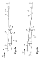
- the device 131 has flexible means 130 in the form of a leaf spring or a leaf spring strands extending substantially parallel to the longitudinal main direction 28 of the mast 2.
- the flexible means 130 are constrained in permanence even when this entry 22 is not subjected to bending moment, which explains their shape slightly curved down represented on this Figure 4a.
- the flexible means 130 comprise a first end 130a integral with first means of link 132 themselves integral with the structure secondary front 10 of the mast 2, as well as a second end 130b integral with second connecting means 134 themselves integral with the fairing 26.
- this device assembly 131 of the fairing 26 lies in the fact that the second connecting means 134 have a set primary 140 secured to the fairing 26, as well as a secondary assembly 142 integral with the second end 130b of the flexible means 130, and that the primary and secondary sets 140 and 142 are connected between them using a pivot link 144.
- pivot link 144 is arranged to allow the described operation above, to generate permanent contact between the fairing 26 and the mast 2.
- this pivot link 144 could be presented as being arranged so that its axis is substantially parallel to an axis according to which the moment of bending applied to the motor 4, or that its axis is substantially orthogonal to a vertical plane passing by the longitudinal main direction 28 of the mast 2, when the aircraft is on the ground.
- the mast 2 being fixed on an upper end of the motor 4, the above vertical plane would be substantially confused with a sharp vertical plane diametrically and longitudinally the motor 4.
- the pivot link 144 is located at near a middle portion 146 of the fairing 26, considered according to the longitudinal main direction 28
- the pivot link 144 is arranged below and in the vertical extension of this middle portion 146, which as an example illustrative, can represent half the width right 1 (not referenced in this figure) of the fairing 26 in the form of annular sector.
- the vertical distance D between the middle portion 146 and the pivot connection 144 corresponds approximately to one quarter of the right width 1 of the fairing 26 in the form of annular sector.
- the whole primary 140 of the second connecting means 134 is consisting of a single primary part attached below of the middle portion 146 of the fairing 26, on a reinforcement 147 integral with the latter. Without leaving the framework of the invention, it would also be possible to provide that the only primary part 140 be directly attached to the middle portion 146 of the fairing 26.
- the secondary set 142 of these second connecting means 134 consists of a single secondary part connected to the primary part 140 using the pivot connection 144, the latter taking the shape of a pivot axis 148 around which can rotate each of these primary and secondary parts 140 and 142.
- pivot axis 148 could be attached to one of the two rooms primary and secondary education 140 and 142, the other pieces 140 and 142 then being able to turn around of this same axis 148.
- the front part of the fairing 26 is plated against the portion 36 of the air inlet 22, this portion 36 protruding rearward and presenting a slight step down to allow a perfect aerodynamic continuity between the two elements 22 and 26.
- the rear part of the fairing 26 is in turn pressed against a portion 150 of the secondary structure before 10, this portion 150 protruding forward and presenting a slight step down to allow a perfect aerodynamic continuity between the two elements 10 and 26.
- Teflon supports 152 and 154 respectively arranged between the rear portion of the fairing 26 and the portion 150, and between the front portion of the fairing 26 and the portion 36.
- Teflon 152 and 154 in the form of platelets can indifferently be integral with the portions 36,150, or of the fairing 26.
- the second end 130b of these the latter is first fixed jointly and severally secondary part 142, for example using a simple screw.
- first end 130a of these flexible means 130 is introduced inside a housing 156 provided on a base 158 belonging to the first connection means 132, this base 158 being fixed solidarily at a front end of the structure secondary front 10 of the mast 2.
- flexible means 130 are abutting within the housing 156, but are not yet constrained. At this As such, it is noted that this pre-assembly state of flexible means 130 is shown in dotted lines on FIG. 5, these same means 130 then adopting a substantially straight shape symbolizing the absence of constraint.
- the first means of connection 132 further include constraint means flexible means 130, these means of implementation constraint that could for example take the form of a or several screws 160 mounted on the base 158 and being associated with a support plate 162. Indeed, as this is clearly shown in Figure 5, the screwing down the screws 160 into the base 158 causes a displacement also vertical downwards of the support plate 162, which then pushes on the flexible means 130 at both ends 130a and 130b respectively blocked in the housing 156 and on the secondary room 142. In this way ,.
- the secondary part 142 secured to the second end 130b rotates slightly around the pivot axis 148 in the direction of the needles of a watch as represented by the arrow P, and the flexible means 130 are thus curved progressively downward by developing a restoring force ensuring the plating of the fairing 26 on the portions 36 and 150. It is specified that once the screws are screwed 160 completed, the flexible means 130 are maintained fixed by clamping between the base 158 and the plate 162.
- the flexible means 130 are consisting of a plurality of flexible blades 164 superimposed in the sense of height, and extending so each substantially substantially parallel to the direction main longitudinal 28 of the mast 2.
- the flexible means 130 consist of two identical flexible blades 164 and superimposed, these blades 164 being preferably leaf spring type.
- a mounting device 231 of the fairing 26, according to another preferred embodiment of the present invention.
- this device 231 is likely to equip the assemblies 1 of the aircraft according to the invention, at the same as the mounting device 131 described above.
- the second connecting means 134 are always attached to the fairing 26, while the first connecting means 132 are no longer attached to the mast 2, but attached to a rear end of the entrance 22 air motor 4.
- the means flexible 130 are more constrained when the motor 4 is not subject to bending moment when there is is precisely subject, this particularity ensuring a permanent contact between the rear part of the fairing 26 and the secondary structure before 10 of the mast 2.
- the upward movement Ma tends to decrease the restoring force generated by flexible means 130, even if it is still sufficient to cause a plating of the fairing 26 against the mast 2, whatever the positions relative to the latter and the air inlet 22.
- the mounting device 231 is advantageous in that it allows you to completely remove the risk of scooping, as long as the flow aerodynamic tends to flatten the fairing 26 simultaneously against the secondary structure before 10 of the mast 2, and against the rear end of the entrance of air 22.
- the fairing 26 is approximately as if there was a simple pivot connection between the back part of this fairing 26 and the secondary structure before 10 of the mast 2.
Landscapes
- Engineering & Computer Science (AREA)
- Aviation & Aerospace Engineering (AREA)
- Structures Of Non-Positive Displacement Pumps (AREA)
- Aerodynamic Tests, Hydrodynamic Tests, Wind Tunnels, And Water Tanks (AREA)
- Cooling, Air Intake And Gas Exhaust, And Fuel Tank Arrangements In Propulsion Units (AREA)
- Connection Of Plates (AREA)
- Mattresses And Other Support Structures For Chairs And Beds (AREA)
Applications Claiming Priority (2)
| Application Number | Priority Date | Filing Date | Title |
|---|---|---|---|
| FR0350715A FR2861364B1 (fr) | 2003-10-22 | 2003-10-22 | Dispositif de montage d'un carenage dispose entre une entree d'air d'un moteur d'aeronef et un mat. |
| FR0350715 | 2003-10-22 |
Publications (2)
| Publication Number | Publication Date |
|---|---|
| EP1535840A1 true EP1535840A1 (de) | 2005-06-01 |
| EP1535840B1 EP1535840B1 (de) | 2006-10-04 |
Family
ID=34400910
Family Applications (1)
| Application Number | Title | Priority Date | Filing Date |
|---|---|---|---|
| EP04292493A Expired - Lifetime EP1535840B1 (de) | 2003-10-22 | 2004-10-20 | Anordnung mit einer Befestigungsvorrichtung für eine Verkleidung zwischen einem Lufteinlass eines Flugzeugtriebwerkes und eines Pylons |
Country Status (7)
| Country | Link |
|---|---|
| US (1) | US7147185B2 (de) |
| EP (1) | EP1535840B1 (de) |
| AT (1) | ATE341485T1 (de) |
| CA (1) | CA2485435C (de) |
| DE (1) | DE602004002655T2 (de) |
| ES (1) | ES2273185T3 (de) |
| FR (1) | FR2861364B1 (de) |
Cited By (2)
| Publication number | Priority date | Publication date | Assignee | Title |
|---|---|---|---|---|
| EP3543140A1 (de) * | 2018-03-22 | 2019-09-25 | Airbus Operations S.A.S. | Frontseitige verkleidung eines luftfahrzeug-pylons mit einer beweglichen kappe und ein luftfahrzeug, das mit einer solchen frontverkleidung ausgestattet ist |
| EP4001120A1 (de) * | 2020-11-24 | 2022-05-25 | Airbus Operations (S.A.S.) | Baugruppe für ein luftfahrzeug mit einem mast und einer gondel, die eine haube umfasst, die mit spann- und zentriersystemen ausgestattet ist |
Families Citing this family (15)
| Publication number | Priority date | Publication date | Assignee | Title |
|---|---|---|---|---|
| FR2902406B1 (fr) * | 2006-06-20 | 2008-07-18 | Airbus France Sas | Carenage pour mat de suspension d'un turbomoteur a une aile d'aeronef |
| FR2903075B1 (fr) * | 2006-06-29 | 2008-10-10 | Airbus France Sas | Dispositif d'articulation d'un capot de nacelle de moteur d'aeronef sur une structure portante |
| FR2903666B1 (fr) * | 2006-07-11 | 2008-10-10 | Airbus France Sas | Ensemble moteur pour aeronef comprenant un capotage aerodynamique de jonction monte sur deux elements distincts |
| FR2915461B1 (fr) * | 2007-04-24 | 2009-06-05 | Airbus France Sas | Agencement d'entree d'air pour vehicule, notamment un aeronef. |
| FR2933957B1 (fr) * | 2008-07-18 | 2010-07-30 | Airbus France | Dispositif pour ceinturer une nacelle d'aeronef |
| FR2933956B1 (fr) * | 2008-07-18 | 2010-07-30 | Airbus France | Dispositif pour ceinturer une nacelle d'aeronef |
| FR2936778B1 (fr) * | 2008-10-07 | 2011-06-10 | Airbus France | Agencement d'entree d'air pour aeronef |
| FR2961173B1 (fr) | 2010-06-09 | 2012-06-22 | Airbus Operations Sas | Nacelle incorporant une entree d'air au niveau d'une casquette |
| EP3024729B1 (de) | 2013-07-26 | 2022-04-27 | MRA Systems, LLC | Triebwerkspylon für luftfahrzeug |
| FR3010049B1 (fr) * | 2013-09-04 | 2017-03-31 | Snecma | Structure de liaison moteur-nacelle a secteurs de virole pivotants |
| FR3011584B1 (fr) * | 2013-10-04 | 2018-02-23 | Safran Aircraft Engines | Extension de carter intermediaire |
| FR3040737B1 (fr) * | 2015-09-04 | 2017-09-22 | Snecma | Ensemble propulsif muni de parties de carter decouplables |
| FR3114300A1 (fr) * | 2020-09-21 | 2022-03-25 | Airbus Operations (S.A.S.) | Assemblage d’un moteur avec un mat d’aeronef |
| US11878808B2 (en) * | 2022-04-05 | 2024-01-23 | Rohr, Inc. | Nacelle inlet structure fitting with locator clip and hoist bracket |
| FR3163054A1 (fr) * | 2024-06-10 | 2025-12-12 | Safran Nacelles | Ensemble propulsif pour un aéronef avec carénage pour pylône amélioré |
Citations (1)
| Publication number | Priority date | Publication date | Assignee | Title |
|---|---|---|---|---|
| GB499846A (en) * | 1936-07-25 | 1939-01-30 | Nl Vliegtuigenfabriek Nv | Improvements in or relating to fastenings for cowlings, inspection doors and the like on aircraft and other means of transport |
Family Cites Families (4)
| Publication number | Priority date | Publication date | Assignee | Title |
|---|---|---|---|---|
| US3347578A (en) * | 1964-11-18 | 1967-10-17 | Boeing Co | Flush-type safety latch |
| FR2291091A1 (fr) * | 1974-11-13 | 1976-06-11 | Snecma | Dispositif de montage sur avion d'un turboreacteur |
| US4474346A (en) * | 1982-07-02 | 1984-10-02 | The Boeing Company | Collapsible cowl structure for gas-turbine engine strut |
| US4555078A (en) * | 1983-12-27 | 1985-11-26 | Societe Belge D'exploitation De La Navigation Aerienne (Sabena) | Apparatus for the suspension of an aircraft engine cowling |
-
2003
- 2003-10-22 FR FR0350715A patent/FR2861364B1/fr not_active Expired - Fee Related
-
2004
- 2004-10-01 US US10/954,192 patent/US7147185B2/en not_active Expired - Lifetime
- 2004-10-19 CA CA2485435A patent/CA2485435C/en not_active Expired - Fee Related
- 2004-10-20 DE DE602004002655T patent/DE602004002655T2/de not_active Expired - Lifetime
- 2004-10-20 EP EP04292493A patent/EP1535840B1/de not_active Expired - Lifetime
- 2004-10-20 ES ES04292493T patent/ES2273185T3/es not_active Expired - Lifetime
- 2004-10-20 AT AT04292493T patent/ATE341485T1/de not_active IP Right Cessation
Patent Citations (1)
| Publication number | Priority date | Publication date | Assignee | Title |
|---|---|---|---|---|
| GB499846A (en) * | 1936-07-25 | 1939-01-30 | Nl Vliegtuigenfabriek Nv | Improvements in or relating to fastenings for cowlings, inspection doors and the like on aircraft and other means of transport |
Cited By (5)
| Publication number | Priority date | Publication date | Assignee | Title |
|---|---|---|---|---|
| EP3543140A1 (de) * | 2018-03-22 | 2019-09-25 | Airbus Operations S.A.S. | Frontseitige verkleidung eines luftfahrzeug-pylons mit einer beweglichen kappe und ein luftfahrzeug, das mit einer solchen frontverkleidung ausgestattet ist |
| FR3079215A1 (fr) * | 2018-03-22 | 2019-09-27 | Airbus Operations | Carenage avant d'un mat d'aeronef comprenant une coiffe mobile et aeronef equipe dudit carenage avant |
| US11034458B2 (en) | 2018-03-22 | 2021-06-15 | Airbus Operations S.A.S. | Front fairing of an aircraft pylon comprising a mobile shroud and aircraft equipped with said front fairing |
| EP4001120A1 (de) * | 2020-11-24 | 2022-05-25 | Airbus Operations (S.A.S.) | Baugruppe für ein luftfahrzeug mit einem mast und einer gondel, die eine haube umfasst, die mit spann- und zentriersystemen ausgestattet ist |
| US11814184B2 (en) | 2020-11-24 | 2023-11-14 | Airbus Operations Sas | Assembly for an aircraft having a pylon and a nacelle comprising a visor fitted with tensioning systems and centering systems |
Also Published As
| Publication number | Publication date |
|---|---|
| US7147185B2 (en) | 2006-12-12 |
| CA2485435A1 (en) | 2005-04-22 |
| DE602004002655D1 (de) | 2006-11-16 |
| ES2273185T3 (es) | 2007-05-01 |
| ATE341485T1 (de) | 2006-10-15 |
| FR2861364B1 (fr) | 2006-02-03 |
| US20060060697A1 (en) | 2006-03-23 |
| FR2861364A1 (fr) | 2005-04-29 |
| EP1535840B1 (de) | 2006-10-04 |
| DE602004002655T2 (de) | 2007-08-16 |
| CA2485435C (en) | 2012-05-15 |
Similar Documents
| Publication | Publication Date | Title |
|---|---|---|
| CA2697380C (fr) | Berceau de support de capot de soufflante monte sur le mat d'accrochage et sur l'entree d'air de la nacelle | |
| EP1535840A1 (de) | Befestigungsvorrichtung für eine Verkleidung zwischen einem Lufteinlass eines Flugzeugtriebwerkes und eines Pylons | |
| EP2038176B1 (de) | Motoranordnung für ein luftfahrzeug mit an zwei getrennten elementen angebrachter aerodynamischer kupplungsverteilung | |
| CA2623760C (fr) | Ensemble moteur pour aeronef comprenant un moteur ainsi qu'un dispositif d'accrochage d'un tel moteur | |
| EP2038175B1 (de) | Triebwerksanordnung für ein flugzeug mit stützgestell für eine auf zwei separaten elementen montierte lüfterhaube | |
| FR2978730A1 (fr) | Berceau d'articulation de capots de soufflante supportes par ces capots en position fermee | |
| CA2652317A1 (fr) | Dispositif d'accrochage d'un moteur d'aeronef | |
| FR2891244A1 (fr) | Mat d'accrochage de moteur pour aeronef | |
| CA2715809C (fr) | Ensemble moteur pour aeronef comprenant un turboreacteur avec des structures de renfort reliant le carter de soufflante au carter central | |
| FR3040369A1 (fr) | Ensemble moteur d'aeronef comprenant une attache moteur avant amelioree | |
| WO2006021721A1 (fr) | Ensemble moteur pour aeronef | |
| CA2575982C (fr) | Ensemble moteur pour aeronef | |
| FR2963320A1 (fr) | Attache moteur avant amelioree pour moteur d'aeronef | |
| EP1571082A1 (de) | Aufhängevorrichtung eines Flugzeugtriebwerks an einem Flügelpylon | |
| CA2608944C (fr) | Ensemble moteur pour aeronef | |
| EP2352674B1 (de) | Flugzeugmotor mit starrem modularem aufbau für einen montagemast | |
| EP2188178B1 (de) | Triebwerksgondel zum einbau in ein flugzeug | |
| FR3009542A1 (fr) | Assemblage pour aeronef comprenant un panneau d'acces aux articulations d'un capot de nacelle monte pivotant sur un dispositif d'accrochage de moteur d'aeronef | |
| FR2887522A1 (fr) | Ensemble pour aeronef comprenant un element de voilure ainsi qu'un mat d'accrochage | |
| EP2447158A2 (de) | Verkleidung eines Luftfahrzeugs, die mit Mitteln zur Begrenzung der Stauphänomene magnetischer Art ausgestattet ist | |
| FR3009543A1 (fr) | Assemblage pour aeronef comprenant un panneau d'acces aux articulations d'un capot de nacelle deplacable par cooperation entre une rampe et un organe d'appui | |
| FR3147251A1 (fr) | Ensemble propulsif pour aéronef comportant un turboréacteur, un mât et des moyens d’accrochage du turboréacteur au mât | |
| FR2909639A1 (fr) | Assemblage pour aeronef comprenant un panneau retractable formant porte d'acces aux articulations d'un capot de nacelle |
Legal Events
| Date | Code | Title | Description |
|---|---|---|---|
| REG | Reference to a national code |
Ref country code: SE Ref legal event code: TRGR |
|
| PUAI | Public reference made under article 153(3) epc to a published international application that has entered the european phase |
Free format text: ORIGINAL CODE: 0009012 |
|
| AK | Designated contracting states |
Kind code of ref document: A1 Designated state(s): AT BE BG CH CY CZ DE DK EE ES FI FR GB GR HU IE IT LI LU MC NL PL PT RO SE SI SK TR |
|
| AX | Request for extension of the european patent |
Extension state: AL HR LT LV MK |
|
| 17P | Request for examination filed |
Effective date: 20050715 |
|
| AKX | Designation fees paid |
Designated state(s): AT BE BG CH CY CZ DE DK EE ES FI FR GB GR HU IE IT LI LU MC NL PL PT RO SE SI SK TR |
|
| RTI1 | Title (correction) |
Free format text: ARRANGEMENT FOR AIRCRAFT COMPRISING A DEVICE FOR MOUNTING A FAIRING BETWEEN A NACELLE OF AN AIRCRAFT ENGINE AND A PYLON |
|
| GRAP | Despatch of communication of intention to grant a patent |
Free format text: ORIGINAL CODE: EPIDOSNIGR1 |
|
| GRAS | Grant fee paid |
Free format text: ORIGINAL CODE: EPIDOSNIGR3 |
|
| GRAA | (expected) grant |
Free format text: ORIGINAL CODE: 0009210 |
|
| AK | Designated contracting states |
Kind code of ref document: B1 Designated state(s): AT BE BG CH CY CZ DE DK EE ES FI FR GB GR HU IE IT LI LU MC NL PL PT RO SE SI SK TR |
|
| PG25 | Lapsed in a contracting state [announced via postgrant information from national office to epo] |
Ref country code: SI Free format text: LAPSE BECAUSE OF FAILURE TO SUBMIT A TRANSLATION OF THE DESCRIPTION OR TO PAY THE FEE WITHIN THE PRESCRIBED TIME-LIMIT Effective date: 20061004 Ref country code: IT Free format text: LAPSE BECAUSE OF FAILURE TO SUBMIT A TRANSLATION OF THE DESCRIPTION OR TO PAY THE FEE WITHIN THE PRESCRIBED TIME-LIMIT;WARNING: LAPSES OF ITALIAN PATENTS WITH EFFECTIVE DATE BEFORE 2007 MAY HAVE OCCURRED AT ANY TIME BEFORE 2007. THE CORRECT EFFECTIVE DATE MAY BE DIFFERENT FROM THE ONE RECORDED. Effective date: 20061004 Ref country code: CZ Free format text: LAPSE BECAUSE OF FAILURE TO SUBMIT A TRANSLATION OF THE DESCRIPTION OR TO PAY THE FEE WITHIN THE PRESCRIBED TIME-LIMIT Effective date: 20061004 Ref country code: AT Free format text: LAPSE BECAUSE OF FAILURE TO SUBMIT A TRANSLATION OF THE DESCRIPTION OR TO PAY THE FEE WITHIN THE PRESCRIBED TIME-LIMIT Effective date: 20061004 Ref country code: NL Free format text: LAPSE BECAUSE OF FAILURE TO SUBMIT A TRANSLATION OF THE DESCRIPTION OR TO PAY THE FEE WITHIN THE PRESCRIBED TIME-LIMIT Effective date: 20061004 Ref country code: IE Free format text: LAPSE BECAUSE OF FAILURE TO SUBMIT A TRANSLATION OF THE DESCRIPTION OR TO PAY THE FEE WITHIN THE PRESCRIBED TIME-LIMIT Effective date: 20061004 Ref country code: SK Free format text: LAPSE BECAUSE OF FAILURE TO SUBMIT A TRANSLATION OF THE DESCRIPTION OR TO PAY THE FEE WITHIN THE PRESCRIBED TIME-LIMIT Effective date: 20061004 Ref country code: FI Free format text: LAPSE BECAUSE OF FAILURE TO SUBMIT A TRANSLATION OF THE DESCRIPTION OR TO PAY THE FEE WITHIN THE PRESCRIBED TIME-LIMIT Effective date: 20061004 Ref country code: RO Free format text: LAPSE BECAUSE OF FAILURE TO SUBMIT A TRANSLATION OF THE DESCRIPTION OR TO PAY THE FEE WITHIN THE PRESCRIBED TIME-LIMIT Effective date: 20061004 Ref country code: PL Free format text: LAPSE BECAUSE OF FAILURE TO SUBMIT A TRANSLATION OF THE DESCRIPTION OR TO PAY THE FEE WITHIN THE PRESCRIBED TIME-LIMIT Effective date: 20061004 |
|
| REG | Reference to a national code |
Ref country code: GB Ref legal event code: FG4D Free format text: NOT ENGLISH |
|
| PG25 | Lapsed in a contracting state [announced via postgrant information from national office to epo] |
Ref country code: MC Free format text: LAPSE BECAUSE OF NON-PAYMENT OF DUE FEES Effective date: 20061031 |
|
| REG | Reference to a national code |
Ref country code: CH Ref legal event code: EP |
|
| REG | Reference to a national code |
Ref country code: IE Ref legal event code: FG4D Free format text: LANGUAGE OF EP DOCUMENT: FRENCH |
|
| REF | Corresponds to: |
Ref document number: 602004002655 Country of ref document: DE Date of ref document: 20061116 Kind code of ref document: P |
|
| PG25 | Lapsed in a contracting state [announced via postgrant information from national office to epo] |
Ref country code: BG Free format text: LAPSE BECAUSE OF FAILURE TO SUBMIT A TRANSLATION OF THE DESCRIPTION OR TO PAY THE FEE WITHIN THE PRESCRIBED TIME-LIMIT Effective date: 20070104 Ref country code: DK Free format text: LAPSE BECAUSE OF FAILURE TO SUBMIT A TRANSLATION OF THE DESCRIPTION OR TO PAY THE FEE WITHIN THE PRESCRIBED TIME-LIMIT Effective date: 20070104 |
|
| PG25 | Lapsed in a contracting state [announced via postgrant information from national office to epo] |
Ref country code: PT Free format text: LAPSE BECAUSE OF FAILURE TO SUBMIT A TRANSLATION OF THE DESCRIPTION OR TO PAY THE FEE WITHIN THE PRESCRIBED TIME-LIMIT Effective date: 20070316 |
|
| NLV1 | Nl: lapsed or annulled due to failure to fulfill the requirements of art. 29p and 29m of the patents act | ||
| REG | Reference to a national code |
Ref country code: ES Ref legal event code: FG2A Ref document number: 2273185 Country of ref document: ES Kind code of ref document: T3 |
|
| REG | Reference to a national code |
Ref country code: IE Ref legal event code: FD4D |
|
| PLBE | No opposition filed within time limit |
Free format text: ORIGINAL CODE: 0009261 |
|
| STAA | Information on the status of an ep patent application or granted ep patent |
Free format text: STATUS: NO OPPOSITION FILED WITHIN TIME LIMIT |
|
| 26N | No opposition filed |
Effective date: 20070705 |
|
| BERE | Be: lapsed |
Owner name: AIRBUS FRANCE Effective date: 20061031 |
|
| PG25 | Lapsed in a contracting state [announced via postgrant information from national office to epo] |
Ref country code: GR Free format text: LAPSE BECAUSE OF FAILURE TO SUBMIT A TRANSLATION OF THE DESCRIPTION OR TO PAY THE FEE WITHIN THE PRESCRIBED TIME-LIMIT Effective date: 20070105 |
|
| PG25 | Lapsed in a contracting state [announced via postgrant information from national office to epo] |
Ref country code: EE Free format text: LAPSE BECAUSE OF FAILURE TO SUBMIT A TRANSLATION OF THE DESCRIPTION OR TO PAY THE FEE WITHIN THE PRESCRIBED TIME-LIMIT Effective date: 20061004 |
|
| PG25 | Lapsed in a contracting state [announced via postgrant information from national office to epo] |
Ref country code: LU Free format text: LAPSE BECAUSE OF NON-PAYMENT OF DUE FEES Effective date: 20061020 Ref country code: TR Free format text: LAPSE BECAUSE OF FAILURE TO SUBMIT A TRANSLATION OF THE DESCRIPTION OR TO PAY THE FEE WITHIN THE PRESCRIBED TIME-LIMIT Effective date: 20061004 Ref country code: HU Free format text: LAPSE BECAUSE OF FAILURE TO SUBMIT A TRANSLATION OF THE DESCRIPTION OR TO PAY THE FEE WITHIN THE PRESCRIBED TIME-LIMIT Effective date: 20070405 |
|
| PG25 | Lapsed in a contracting state [announced via postgrant information from national office to epo] |
Ref country code: CY Free format text: LAPSE BECAUSE OF FAILURE TO SUBMIT A TRANSLATION OF THE DESCRIPTION OR TO PAY THE FEE WITHIN THE PRESCRIBED TIME-LIMIT Effective date: 20061004 |
|
| REG | Reference to a national code |
Ref country code: CH Ref legal event code: PL |
|
| PG25 | Lapsed in a contracting state [announced via postgrant information from national office to epo] |
Ref country code: BE Free format text: LAPSE BECAUSE OF FAILURE TO SUBMIT A TRANSLATION OF THE DESCRIPTION OR TO PAY THE FEE WITHIN THE PRESCRIBED TIME-LIMIT Effective date: 20061031 |
|
| PG25 | Lapsed in a contracting state [announced via postgrant information from national office to epo] |
Ref country code: LI Free format text: LAPSE BECAUSE OF NON-PAYMENT OF DUE FEES Effective date: 20081031 Ref country code: CH Free format text: LAPSE BECAUSE OF NON-PAYMENT OF DUE FEES Effective date: 20081031 |
|
| REG | Reference to a national code |
Ref country code: GB Ref legal event code: 732E Free format text: REGISTERED BETWEEN 20110721 AND 20110727 |
|
| REG | Reference to a national code |
Ref country code: FR Ref legal event code: CJ Effective date: 20110916 Ref country code: FR Ref legal event code: CD Owner name: AIRBUS HOLDING, FR Effective date: 20110916 Ref country code: FR Ref legal event code: CA Effective date: 20110916 Ref country code: FR Ref legal event code: TP Owner name: AIRBUS HOLDING, FR Effective date: 20110913 |
|
| REG | Reference to a national code |
Ref country code: ES Ref legal event code: PC2A Owner name: AIRBUS OPERATIONS SAS Effective date: 20120308 |
|
| REG | Reference to a national code |
Ref country code: DE Ref legal event code: R082 Ref document number: 602004002655 Country of ref document: DE Representative=s name: HENKEL, BREUER & PARTNER, DE |
|
| REG | Reference to a national code |
Ref country code: DE Ref legal event code: R081 Ref document number: 602004002655 Country of ref document: DE Owner name: AIRBUS OPERATIONS SAS, FR Free format text: FORMER OWNER: AIRBUS FRANCE, TOULOUSE, FR Effective date: 20120326 Ref country code: DE Ref legal event code: R082 Ref document number: 602004002655 Country of ref document: DE Representative=s name: PATENTANWAELTE HENKEL, BREUER & PARTNER, DE Effective date: 20120326 |
|
| PGFP | Annual fee paid to national office [announced via postgrant information from national office to epo] |
Ref country code: SE Payment date: 20121019 Year of fee payment: 9 Ref country code: ES Payment date: 20121026 Year of fee payment: 9 |
|
| REG | Reference to a national code |
Ref country code: SE Ref legal event code: EUG |
|
| PG25 | Lapsed in a contracting state [announced via postgrant information from national office to epo] |
Ref country code: SE Free format text: LAPSE BECAUSE OF NON-PAYMENT OF DUE FEES Effective date: 20131021 |
|
| REG | Reference to a national code |
Ref country code: ES Ref legal event code: FD2A Effective date: 20150504 |
|
| PG25 | Lapsed in a contracting state [announced via postgrant information from national office to epo] |
Ref country code: ES Free format text: LAPSE BECAUSE OF NON-PAYMENT OF DUE FEES Effective date: 20131021 |
|
| REG | Reference to a national code |
Ref country code: FR Ref legal event code: PLFP Year of fee payment: 12 |
|
| REG | Reference to a national code |
Ref country code: FR Ref legal event code: PLFP Year of fee payment: 13 |
|
| PGFP | Annual fee paid to national office [announced via postgrant information from national office to epo] |
Ref country code: IT Payment date: 20161024 Year of fee payment: 13 |
|
| REG | Reference to a national code |
Ref country code: FR Ref legal event code: PLFP Year of fee payment: 14 |
|
| REG | Reference to a national code |
Ref country code: FR Ref legal event code: PLFP Year of fee payment: 15 |
|
| PG25 | Lapsed in a contracting state [announced via postgrant information from national office to epo] |
Ref country code: IT Free format text: LAPSE BECAUSE OF NON-PAYMENT OF DUE FEES Effective date: 20171020 |
|
| PGFP | Annual fee paid to national office [announced via postgrant information from national office to epo] |
Ref country code: DE Payment date: 20181019 Year of fee payment: 15 |
|
| PGFP | Annual fee paid to national office [announced via postgrant information from national office to epo] |
Ref country code: FR Payment date: 20191028 Year of fee payment: 16 |
|
| PGFP | Annual fee paid to national office [announced via postgrant information from national office to epo] |
Ref country code: GB Payment date: 20191021 Year of fee payment: 16 |
|
| REG | Reference to a national code |
Ref country code: DE Ref legal event code: R119 Ref document number: 602004002655 Country of ref document: DE |
|
| PG25 | Lapsed in a contracting state [announced via postgrant information from national office to epo] |
Ref country code: DE Free format text: LAPSE BECAUSE OF NON-PAYMENT OF DUE FEES Effective date: 20200501 |
|
| GBPC | Gb: european patent ceased through non-payment of renewal fee |
Effective date: 20201020 |
|
| PG25 | Lapsed in a contracting state [announced via postgrant information from national office to epo] |
Ref country code: FR Free format text: LAPSE BECAUSE OF NON-PAYMENT OF DUE FEES Effective date: 20201031 |
|
| PG25 | Lapsed in a contracting state [announced via postgrant information from national office to epo] |
Ref country code: GB Free format text: LAPSE BECAUSE OF NON-PAYMENT OF DUE FEES Effective date: 20201020 |