EP1535708B1 - Outil de coupe pour une tondeuse électrique - Google Patents
Outil de coupe pour une tondeuse électrique Download PDFInfo
- Publication number
- EP1535708B1 EP1535708B1 EP20040028058 EP04028058A EP1535708B1 EP 1535708 B1 EP1535708 B1 EP 1535708B1 EP 20040028058 EP20040028058 EP 20040028058 EP 04028058 A EP04028058 A EP 04028058A EP 1535708 B1 EP1535708 B1 EP 1535708B1
- Authority
- EP
- European Patent Office
- Prior art keywords
- cutting tool
- comb
- clipping
- cutting
- tool according
- Prior art date
- Legal status (The legal status is an assumption and is not a legal conclusion. Google has not performed a legal analysis and makes no representation as to the accuracy of the status listed.)
- Expired - Lifetime
Links
- 210000004209 hair Anatomy 0.000 title claims description 38
- 208000019300 CLIPPERS Diseases 0.000 title claims description 25
- 208000021930 chronic lymphocytic inflammation with pontine perivascular enhancement responsive to steroids Diseases 0.000 title claims description 25
- 238000010438 heat treatment Methods 0.000 claims description 17
- 238000004659 sterilization and disinfection Methods 0.000 claims description 10
- 239000004020 conductor Substances 0.000 claims description 4
- 230000001960 triggered effect Effects 0.000 claims description 4
- 239000000919 ceramic Substances 0.000 claims description 3
- 238000010008 shearing Methods 0.000 description 42
- 230000001681 protective effect Effects 0.000 description 13
- 238000000034 method Methods 0.000 description 7
- 238000007789 sealing Methods 0.000 description 6
- 241000700605 Viruses Species 0.000 description 4
- 244000052769 pathogen Species 0.000 description 4
- 241000894006 Bacteria Species 0.000 description 3
- 102000029797 Prion Human genes 0.000 description 2
- 108091000054 Prion Proteins 0.000 description 2
- 230000000694 effects Effects 0.000 description 2
- 230000003719 hair strength Effects 0.000 description 2
- 244000005700 microbiome Species 0.000 description 2
- 230000001717 pathogenic effect Effects 0.000 description 2
- 230000000284 resting effect Effects 0.000 description 2
- 208000030507 AIDS Diseases 0.000 description 1
- 241000193738 Bacillus anthracis Species 0.000 description 1
- 235000014469 Bacillus subtilis Nutrition 0.000 description 1
- 241001112696 Clostridia Species 0.000 description 1
- 241000991587 Enterovirus C Species 0.000 description 1
- 241000233866 Fungi Species 0.000 description 1
- 206010034133 Pathogen resistance Diseases 0.000 description 1
- 240000004808 Saccharomyces cerevisiae Species 0.000 description 1
- 230000004913 activation Effects 0.000 description 1
- 230000001580 bacterial effect Effects 0.000 description 1
- 244000052616 bacterial pathogen Species 0.000 description 1
- 230000006835 compression Effects 0.000 description 1
- 238000007906 compression Methods 0.000 description 1
- 238000010276 construction Methods 0.000 description 1
- 230000001276 controlling effect Effects 0.000 description 1
- 230000007613 environmental effect Effects 0.000 description 1
- 230000002349 favourable effect Effects 0.000 description 1
- 230000002538 fungal effect Effects 0.000 description 1
- 230000003660 hair regeneration Effects 0.000 description 1
- 208000006454 hepatitis Diseases 0.000 description 1
- 231100000283 hepatitis Toxicity 0.000 description 1
- 208000005252 hepatitis A Diseases 0.000 description 1
- 208000015181 infectious disease Diseases 0.000 description 1
- 238000002955 isolation Methods 0.000 description 1
- 239000011148 porous material Substances 0.000 description 1
- 230000001105 regulatory effect Effects 0.000 description 1
- 239000002689 soil Substances 0.000 description 1
- 241000894007 species Species 0.000 description 1
Images


Classifications
-
- B—PERFORMING OPERATIONS; TRANSPORTING
- B26—HAND CUTTING TOOLS; CUTTING; SEVERING
- B26B—HAND-HELD CUTTING TOOLS NOT OTHERWISE PROVIDED FOR
- B26B19/00—Clippers or shavers operating with a plurality of cutting edges, e.g. hair clippers, dry shavers
- B26B19/38—Details of, or accessories for, hair clippers, or dry shavers, e.g. housings, casings, grips, guards
- B26B19/3806—Accessories
- B26B19/382—Built-in accessories
-
- B—PERFORMING OPERATIONS; TRANSPORTING
- B26—HAND CUTTING TOOLS; CUTTING; SEVERING
- B26B—HAND-HELD CUTTING TOOLS NOT OTHERWISE PROVIDED FOR
- B26B19/00—Clippers or shavers operating with a plurality of cutting edges, e.g. hair clippers, dry shavers
- B26B19/02—Clippers or shavers operating with a plurality of cutting edges, e.g. hair clippers, dry shavers of the reciprocating-cutter type
- B26B19/04—Cutting heads therefor; Cutters therefor; Securing equipment thereof
- B26B19/06—Cutting heads therefor; Cutters therefor; Securing equipment thereof involving co-operating cutting elements both of which have shearing teeth
-
- B—PERFORMING OPERATIONS; TRANSPORTING
- B26—HAND CUTTING TOOLS; CUTTING; SEVERING
- B26B—HAND-HELD CUTTING TOOLS NOT OTHERWISE PROVIDED FOR
- B26B19/00—Clippers or shavers operating with a plurality of cutting edges, e.g. hair clippers, dry shavers
- B26B19/38—Details of, or accessories for, hair clippers, or dry shavers, e.g. housings, casings, grips, guards
- B26B19/3846—Blades; Cutters
-
- B—PERFORMING OPERATIONS; TRANSPORTING
- B26—HAND CUTTING TOOLS; CUTTING; SEVERING
- B26B—HAND-HELD CUTTING TOOLS NOT OTHERWISE PROVIDED FOR
- B26B19/00—Clippers or shavers operating with a plurality of cutting edges, e.g. hair clippers, dry shavers
- B26B19/38—Details of, or accessories for, hair clippers, or dry shavers, e.g. housings, casings, grips, guards
- B26B19/3873—Electric features; Charging; Computing devices
-
- B—PERFORMING OPERATIONS; TRANSPORTING
- B26—HAND CUTTING TOOLS; CUTTING; SEVERING
- B26B—HAND-HELD CUTTING TOOLS NOT OTHERWISE PROVIDED FOR
- B26B19/00—Clippers or shavers operating with a plurality of cutting edges, e.g. hair clippers, dry shavers
- B26B19/38—Details of, or accessories for, hair clippers, or dry shavers, e.g. housings, casings, grips, guards
- B26B19/3873—Electric features; Charging; Computing devices
- B26B19/388—Sensors; Control
-
- B—PERFORMING OPERATIONS; TRANSPORTING
- B26—HAND CUTTING TOOLS; CUTTING; SEVERING
- B26B—HAND-HELD CUTTING TOOLS NOT OTHERWISE PROVIDED FOR
- B26B21/00—Razors of the open or knife type; Safety razors or other shaving implements of the planing type; Hair-trimming devices involving a razor-blade; Equipment therefor
- B26B21/40—Details or accessories
- B26B21/48—Heating means
Definitions
- the invention relates to a cutting set for electric hair cutting machines according to the preamble of claim 1 and a hair clipper according to the preamble of claim 13.
- Such cutting sets and hair clippers are known for example from DE 297 24 477 U1.
- hot scissors Examples of electrically heatable shears are known from DE 196 26 069 A1 or DE 101 07 284 A1.
- the advantage of such scissors is that simultaneously with the cutting the cut surfaces of the individual hairs are sealed with the hot cutting edge. This promotes hair regeneration, should prevent hair splitting and protect the hair from environmental influences. With permanent use the hair gets more volume and shine.
- a disadvantage is the time associated with such, manually operated scissors time for a haircut.
- the aim of the invention is to provide a cutting set for an electric hair clipper or a hair clipper available that allows a sealing of the cut surfaces of the hair analogous to the hot scissors.
- the object is achieved by a cutting set for electric hair clippers with the characterizing features of claim 1 and by a hair clipper with the characterizing features of claim 13.
- the cutting set according to the invention for electric hair clippers has a shearing comb and a shearing ridge resting on the shearing comb, which are fastened via a drive side Driver is oscillating, on, wherein at least one electrically heatable element in the region of the cutting comb and / or the doctor blade is arranged.
- the electrically heatable elements By the electrically heatable elements, the shearing blade and / or the cutting comb is heated, so that when cutting with the hair clipper by the cooperating heated cutting edges of the cutting comb and the doctor blade an effect similar to a hot pair of scissors is achieved.
- the short contact time between the cutting edges and the hair is quite sufficient to ensure the required sealing of the cut surfaces of the cut hair ends.
- Another advantage is that the high temperatures on the cutting set germs, bacteria and pathogens are killed.
- the resulting thermal disinfection leads to a high level of hygiene without any special additional measures.
- an electrically heatable element is arranged in the region of the shearing comb and in the region of the shearing blade.
- the two interacting cutting edges of the cutting comb and the doctor blade thus have the same temperature, which is particularly favorable for the sealing of the cut surfaces of the individual hair.
- the electrically heatable element is a layer connected to the shearing comb or the shearing blade or an insert integrated into the shearing comb or the shearing blade, wherein the layer or insert is thermally bonded to the cutting edges of the shearing comb or of the shearing blade is coupled.
- the at least one electrically heatable element is a ceramic board with an integrated heating conductor, a hybrid heating element, a heating tape, a heating resistor or a transistor.
- the shearing comb is provided with a protective comb.
- the protective comb thermally insulates the outer surfaces of the cutting comb and thereby reliably prevents inadvertent contact between the hot cutting comb and the skin. He thereby excludes any risk of burns to the skin.
- the protective comb is firmly connected to the cutting comb and can not be removed by the user, so that the greatest possible protection is granted.
- the comb-like construction of the protective comb ensures that, on the one hand, the shearing comb is thermally insulated, but on the other hand, the teeth of the shaving comb are largely open, so that the hair can be easily grasped and cut.
- control electronics are provided for the at least one electrically heatable element. This allows a targeted adjustment of the temperature.
- control electronics in the cutting set in the handset of the electric hair clipper or in an external module, which is connected via a supply line to the handset or the cutting set housed.
- control electronics is housed in the cutting set, since in this case the heatable cutting set is independent of the handset and thus already known electrical Hair clippers can be equipped with the new heatable cutting set according to the invention.
- control electronics are powered by a battery or a plug-in transformer for mains operation with power
- the battery is integrated in the handset or in an external module, which is connected via a supply line to the handset or the cutting set is housed or wherein the plug-in transformer is connected via a supply line with the handset or the cutting set.
- the control electronics powered by a battery with power which is housed in an external module and connected directly to the cutting set via a supply line or the control electronics via a plug-in transformer for mains operation with power
- the plug-in transformer is connected via a supply line with the cutting set
- the cutting set is independent of the handset and can thus be used for existing electric hair clippers.
- a temperature sensor is arranged in the shearing comb or shearing blade. This monitors the heating temperature, so that it can be controlled with the help of the control electronics.
- the temperature of the at least one electrically heatable element is set to a specific value, adjustable in several stages or infinitely variable. In order to allow a wider range of applications, a control in stages or a continuous control of the temperature is preferred.
- the speed of the oscillating driver is variable.
- the speed becomes the cutting speed affects what affects the sealing process.
- the sealing process can thus be optimized by varying the speed, wherein the choice of the optimal speed depends on the hair strength of the person to be treated and the working speed of the user.
- a disinfection process can be triggered manually or automatically controlled, in which the cutting set is heated with the drive off for a predetermined time.
- thermoresistance of the microorganisms or pathogens of transmissible diseases to be destroyed a temperature between about 60 ° C and 170 ° C for a heating time between 5 minutes and 1 hour according to the following tables should be considered.
- Temp. In ° C killing time Killed or inactive pathogen resistance levels 80-100 5-10 min Vegetative bacteria, fungi, fungal pores I 105 5-10 min Spores of B. anthracis spores, B. subtilis, HAV / HBV I 121 134 15 min 3 min Native soil spores, spores of B.
- thermophilic Gram-positive rods IV 134 1 h Prions (CJK, vCJK, BSE) V Temp. In ° C killing time Killed or inactive pathogen 62.5 30 min TBC pathogens, pathogenic streptococci, polioviruses 80 30 min Vegetative bacteria, yeasts, molds, all viruses (including AIDS viruses). Exception: hepatitis viruses 98-100 10 min All vegetative bacterial species, all viruses, also hepatitis A, B, C
- an individually predefinable or permanently preset disinfection cycle (temperature and holding time) can thus be provided.
- the activation of the disinfection process can be triggered individually manually, for example via an actuating button attached to the housing or otherwise.
- the triggering can be done automatically when inserting the hair clipper in a corresponding charging stand. This has the advantage that the disinfection is triggered at least during each charging process.
- the disinfection process can also be activated by other criteria, for example at certain intervals, via an integrated control device.
- the thermal disinfection can thus be used even if the hair clipper otherwise conventionally, i. to be operated in the cold state. Furthermore, a heating exceeding the usual operating temperature can be carried out in order to reliably kill particularly resistant microorganisms, such as, for example, the prions reproduced in the table above.
- the hair clipper according to the invention is equipped with a cutting set according to the invention.
- the necessary components for the cutting set such as control and power supply can be arranged in different components of the hair clipper or an external module.
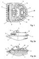
- FIG. 1 shows a first exemplary embodiment of a cutting set 20 with a cutting comb 1 and a shearing blade 2 resting thereon, which can be moved in an oscillating manner parallel to the longitudinal axis of the cutting comb 1 via a driver 9 fixed on the drive side.
- the shearing blade 2 is pressed by two cutting compression springs 10 against the shearing comb.
- the shearing comb 1 is fixed on a cutting set carrier 8 via two screws 13.
- each an electrically heatable element 3 is integrated as a deposit (see Figure 2b).
- the electrically heatable elements 3 are thermally coupled to the shearing comb 1 or the shearing blade 2 and thus heat the cutting edges of the shearing comb 1 and of the shearing blade 2.
- the size and the power of the electrically heatable elements 3 are on the mass of the shearing comb to be heated 1 and 2 of the Schermesserers.
- the heatable elements 3 are, for example, a ceramic board with an integrated heating conductor, a hybrid heating element, a heating tape, a heating resistor or a transistor and are positioned in such a way that that the heating power distribution optimally affects the cutting edges of the cutting comb 1 and the doctor blade 2 to be heated.
- the shearing comb 1 and the shearing blade 2 are insulated by a protective comb 7, which is preferably made of plastic (see Figures 1, 3 and 5).
- the protective comb 7 is firmly connected via the two screws 13 with the cutting comb 1 and can not be removed by the user. It serves to eliminate any risk of burns to the skin.
- the protective comb 7 is comb-shaped, so that the cutting edges of the shearing comb 1 and the shearing blade 2 are partially exposed as in a known Aufsteckkamm. This design of the protective comb 7 ensures that the hair can be easily detected and cut.
- the outer dimensions of the cutting set carrier 8 including the protective comb 7 are designed so that the cutting set 20 according to the invention can be placed on conventional handheld devices 30 for electric hair cutting machines.
- an adjusting lever 11 is mounted, with which the relative position between the cutting comb 1 and the shearing blade 2 and thus the cutting length can be changed.
- the cutting length can also be defined by the design of the protective comb 7 by the distance between the outer surface of the protective comb 7 and the cutting edges of the cutting comb 1 and the doctor blade 2 is selected accordingly.
- the protective comb 7 thus assumes the function of a known Aufsteckkamms in addition to the isolation of the heated cutting edges of the shear comb 1 and the doctor blade 2.
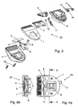
- FIG. 3 shows an exploded view of a second exemplary embodiment of a cutting set 20 according to the invention.
- the electrically heatable element 3, which is connected via supply lines 4 to control electronics 6, is inserted into the cutting comb 1 so that it rests on the cutting comb 1.
- the electrically heatable element 3 comes to lie below the teeth of the cutting comb 1.
- the shearing blade 2 is not heated.
- the control electronics 6 is inserted into a continuous opening of the cutting comb 1.
- the shearing comb 1 is made of a heat-conducting material, so that the cutting edge of the shearing comb 1 is heated via the contact between the shearing comb 1 and the electrically heatable element 3, as soon as the electrically heatable element is heated.
- Not shown is arranged on the cutting comb 1 temperature sensor, which is connected to the control electronics 6 and measures the temperature of the cutting comb 1 and passes on to the control electronics 6 for controlling the temperature.
- the shear comb 1 is inserted into the protective comb 7, from which it is surrounded on the entire back.
- the shearing blade 2 is placed, which is connected to the driver 9 via a contact bridge 12 and is pressed over the two cutting pressure springs 10 to the cutting comb 1.
- two contactors 5 are mounted for contacting between the cutting set 20 and the handset 30. As a contactor 5 stamped and bent parts, contact plates, contact plates or pins can be used.
- the arrangement of the control electronics 6 in the cutting set 20 allows for a suitable power supply independent of the handset 30 operation of the electrically heatable element 3, so that the cutting set 20 according to the invention also can be placed on handsets 30 of already known electric hair clippers.
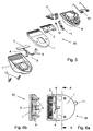
- FIG 5 shows an exploded view of a third embodiment of the cutting set 20 according to the invention, while Figures 6a and 6b show this embodiment in the mounted state.
- This cutting set 20 differs from the first embodiment in that on the cutting comb 1, the electrically heatable element 3, which is connected via the leads 4 to the contactors 5, is placed, while the associated control electronics 6 is not in the cutting set 20, but is arranged for example in the handset 30.
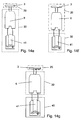
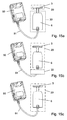
- FIGS. 14a to 14g and 15a to 15c schematically show various possibilities of arranging electrically heatable element 3, control electronics 6 and power supply.
- the different components can be arranged either in the cutting set 20, the hand-held device 30 or an external module 40.
- the dotted line indicates the cutting set 20, while the dashed line symbolize the handset 30 and the solid line the external module 40.
- FIG. 14 a the electrically heatable element 3 is arranged in the cutting set 20, while both the control electronics 6 and the power supply are arranged via a battery 41 in an external module 40, which is connected to the handset 30.
- Figure 14 b shows the same arrangement of the electrically heatable element 3, the control electronics 6 and the battery 41, wherein the external module 40 is coupled directly to the cutting set 20.
- Figures 14c and 14d show an embodiment in which both the electrically heatable element 3 and the control electronics 6 are arranged in the cutting set 20, wherein the power supply via the battery 41 in the external module 40 is done.
- the external module 40 is connected to the handheld device 30, while in the variant illustrated in FIG. 14 d, the external module 40 is connected directly to the cutting set 20.
- FIG. 14e shows the embodiment variant in which the electrically heatable element 3 is arranged in the cutting set 20, while both the control electronics 6 and the battery 41 are arranged in the handset 30.
- both the electrically heatable element 3 and the control electronics 6 may be arranged in the cutting set 20, while the battery 41 is arranged in the handset 30.
- the electrically heatable element 3 is arranged in the cutting set 20, while the control electronics 6 are arranged in the handheld device 30 and the power supply via the battery 41 is realized in the external module 40.
- FIGS 15a to 15c show three embodiments of an electric hair clipper, in which the power supply of the control electronics 6 via a plug transformer 50 which is connected via a supply line 51 either with the handset 30 or the cutting set 20 is realized.
- the electrically heatable element 3 is arranged in the cutting set 20, while the control electronics 6 are arranged in the handset 30.
- the Steckertrafo 50 is connected via the cable 51 to the handset 30.
- both the electrically heatable element 3 and the control electronics 6 are in the cutting set 20 arranged while the Steckertrafo 50 is connected via the supply line 51 to the handset 30.
- the plug-type transformer 50 can be connected directly to the cutting set 20 via the supply line 51.
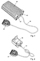
- FIGs 7 and 8 show an embodiment of the cutting set 20, in which the cutting set 20 can be operated completely independently of the handset 30.
- the electrically heatable element 3 and the control electronics 6 are arranged in the cutting set 20.
- the power supply of the control electronics 6 is done as shown in Figure 7 via the external module 40, in which the battery 41 is arranged, and which is connected via a feed line 44 with the cutting set 20 (see also Figure 14d).
- a control element 43 is arranged for switching on and regulating the temperature of the electrically heatable element 3, wherein the temperature of the electrically heatable element 3 is displayed on a display element 42.
- the cutting set 20, in which the electrically heatable element 3 and the control electronics 6 are integrated, is connected via the supply line 51 to the plug-in transformer 50 for mains operation (see also FIG. 15c).
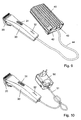
- FIGS. 9 and 10 show two exemplary embodiments in which the power supply is connected to the handheld device 30.
- Figure 9 shows the variant in which the power supply via the battery 41 is implemented in the external module 40, which is connected via the supply line 44 to the handset 30.
- On the handset 30 is an on / off switch 31, with which both the heating function of the electrically heatable element 3 and the cutting function of the cutting set 20 is switched on and off.
- a status indicator 32 is arranged consisting of four LEDs, which informs the user about the current temperature of the electrically heatable element 30 informed. For example, of the four light-emitting diodes of the status indicator 32, the more diodes the warmer the electrically heatable element 3 is, the more diodes are illuminated.
- a display panel may also be arranged on the handset 30, which indicates the absolute temperature of the electrically heatable element 3.
- the embodiment of the handset 30 is identical to the embodiment shown in Figure 9, wherein the power supply of the handset 30 via the plug transformer 50 is realized, which is connected via the supply line 51 to the handset 30.
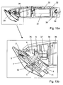
- FIGS. 11 to 13 show an exemplary embodiment in which all the components required for the electrically heatable cutting set 20, such as the electrically heatable element 3, the control electronics 6 and the power supply, are integrated in the handset 30 and the cutting set 20, respectively no external module 40 is needed.
- the electrically heatable element 3 rests on the shearing comb 1 as already described in FIG.
- the control electronics 6 is also integrated in the cutting set 20.
- the battery 41 is disposed in the handset 30 so that the handset 30 can be operated independently of the external module 40 or the network.
- a female connector 39 is recessed to charge the battery 41 when needed.
- the socket 39 is connected via charging contact plates 38 to the battery 41.
- the battery 41 contacts a circuit board 33, which is connected via two supply lines 34 with a motor 36 and serves to control the motor 36.
- the motor 36 is connected via an eccentric 37 with the driver 9 of the cutting set 20, so that over this the shearing blade 20 oscillating with respect to the cutting comb. 1 is movable.
- the speed of the motor 36 and thus the cutting speed can be varied via the on / off switch 31.
- the sealing process when cutting the hair with the heated cutting edges of the cutting set 20 can thus be optimized, the choice of the optimal speed depends on the hair strength of the person to be treated and the working speed of the user.
- the contact between the cutting set 20 and the handset 30 is ensured by the contactor 5, which abut two retaining springs 35 which are connected via the leads 34 to the board 33.
Landscapes
- Life Sciences & Earth Sciences (AREA)
- Forests & Forestry (AREA)
- Engineering & Computer Science (AREA)
- Mechanical Engineering (AREA)
- Dry Shavers And Clippers (AREA)
Claims (13)
- Ensemble de coupe pour tondeuse à cheveux électrique comprenant un peigne de coupe (1) et une lame (2) placée sur le peigne de coupe (1) et pouvant être déplacée de façon oscillante au moyen d'un entraîneur (9) fixé côté entraînement,
caractérisé en ce qu'
au moins un élément (3) pouvant être chauffé électriquement est disposé dans la zone du peigne de coupe (1) et/ou de la lame (2). - Ensemble de coupe selon la revendication 1
caractérisé en ce qu'
un élément (3) pouvant être chauffé électriquement est respectivement disposé dans la zone du peigne de coupe (1) et dans la zone de la lame (2). - Ensemble de coupe selon l'une quelconque des revendications précédentes,
caractérisé en ce que
l'élément (3) pouvant être chauffé électriquement est une couche reliée au peigne de coupe (1) ou à la lame (2), ou un insert intégré dans le peigne de coupe (1) ou la lame (2), la couche ou l'insert étant couplé thermiquement avec les arêtes de coupe du peigne de coupe (1) ou de la lame (2). - Ensemble de coupe selon l'une quelconque des revendications précédentes,
caractérisé en ce qu'
au moins un élément (3) pouvant être chauffé électriquement est une platine en céramique avec conducteur chauffant intégré, un élément chauffant hybride, un ruban chauffant, une résistance chauffante ou un transistor. - Ensemble de coupe selon l'une quelconque des revendications précédentes,
caractérisé en ce que
le peigne de coupe (1) est muni d'un peigne de protection (7). - Ensemble de coupe selon l'une quelconque des revendications précédentes,
caractérisé en ce qu'
une électronique de commande (6) est prévue pour au moins un élément (3) pouvant être chauffé électriquement. - Ensemble de coupe selon la revendication 6,
caractérisé en ce que
l'électronique de commande (6) est logée dans l'ensemble de coupe (20), dans l'appareil portatif (30) de la tondeuse à cheveux électrique ou dans un module extérieur (40) relié par une ligne d'alimentation (44) à l'appareil portatif (30) ou à l'ensemble de coupe (10). - Ensemble de coupe selon la revendication 6 ou 7,
caractérisé en ce que
l'électronique de commande (6) est alimentée en courant par un accumulateur (41) ou par un transformateur à fiche (50) pour un fonctionnement sur secteur, l'accumulateur (41) étant intégré dans l'appareil portatif (30) ou dans un module extérieur (40) relié par une ligne d'alimentation (44) à l'appareil portatif (30) ou à l'ensemble de coupe (20), ou le transformateur à fiche (50) est relié par une ligne d'alimentation (51) à l'appareil portatif (30) ou à l'ensemble de coupe (20). - Ensemble de coupe selon l'une quelconque des revendications précédentes,
caractérisé en ce qu'
un capteur de température est disposé dans le peigne de coupe (1) et/ ou la lame (2). - Ensemble de coupe selon l'une quelconque des revendications précédentes,
caractérisé en ce que
la température d'au moins un élément (3) pouvant être chauffé électriquement est réglée sur une valeur déterminée, sur plusieurs paliers ou en continu. - Ensemble de coupe selon l'une quelconque des revendications précédentes,
caractérisé en ce que
la vitesse de rotation de l'entraîneur (9) oscillant est variable. - Ensemble de coupe selon l'une quelconque des revendications précédentes,
caractérisé en ce qu'
on peut déclencher un processus de désinfection thermique lorsque l'entraînement est arrêté. - Tondeuse à cheveux comprenant un appareil portatif (30) et un ensemble de coupe (20),
caractérisée en ce que
l'ensemble de coupe (20) est configuré selon l'une des revendications 1 à 12.
Applications Claiming Priority (2)
| Application Number | Priority Date | Filing Date | Title |
|---|---|---|---|
| DE2003155154 DE10355154A1 (de) | 2003-11-26 | 2003-11-26 | Schneidsatz für elektrische Haarschneidemaschinen |
| DE10355154 | 2003-11-26 |
Publications (2)
| Publication Number | Publication Date |
|---|---|
| EP1535708A1 EP1535708A1 (fr) | 2005-06-01 |
| EP1535708B1 true EP1535708B1 (fr) | 2006-09-13 |
Family
ID=34442290
Family Applications (1)
| Application Number | Title | Priority Date | Filing Date |
|---|---|---|---|
| EP20040028058 Expired - Lifetime EP1535708B1 (fr) | 2003-11-26 | 2004-11-25 | Outil de coupe pour une tondeuse électrique |
Country Status (3)
| Country | Link |
|---|---|
| EP (1) | EP1535708B1 (fr) |
| DE (2) | DE10355154A1 (fr) |
| ES (1) | ES2271765T3 (fr) |
Families Citing this family (24)
| Publication number | Priority date | Publication date | Assignee | Title |
|---|---|---|---|---|
| JP4697079B2 (ja) * | 2006-07-20 | 2011-06-08 | パナソニック電工株式会社 | シェーバ |
| DE102007015805B4 (de) | 2007-03-30 | 2008-11-13 | Wahl Gmbh | Schneidsatz für elektrische Haarschneidemaschinen |
| DE102007050379A1 (de) * | 2007-10-22 | 2009-04-23 | Braun Gmbh | Haartrimmer |
| US20120110859A1 (en) * | 2010-11-09 | 2012-05-10 | Kammer Carl G | Electric hair trimmer |
| EP4166289A1 (fr) | 2012-01-12 | 2023-04-19 | Spectrum Brands, Inc. | Tondeuse électrique à cheveux |
| US9751228B2 (en) * | 2014-01-14 | 2017-09-05 | The Gillette Company Llc | Shaving cartridges having thermal sensors |
| US10384358B2 (en) | 2014-11-06 | 2019-08-20 | Koninklijke Philips N.V. | Hair clipping device |
| US10652956B2 (en) | 2016-06-22 | 2020-05-12 | The Gillette Company Llc | Personal consumer product with thermal control circuitry and methods thereof |
| EP3351358B1 (fr) | 2017-01-20 | 2019-11-20 | The Gillette Company LLC | Élément chauffant pour un rasoir |
| JP6837221B2 (ja) * | 2017-04-11 | 2021-03-03 | パナソニックIpマネジメント株式会社 | 刃ユニット、および、バリカン |
| AU2019242730A1 (en) | 2018-03-30 | 2020-09-24 | The Gillette Company Llc | Razor handle with movable members |
| JP2021517043A (ja) | 2018-03-30 | 2021-07-15 | ザ ジレット カンパニー リミテッド ライアビリティ カンパニーThe Gillette Company Llc | 枢動部分を有するかみそりハンドル |
| CN111819046B (zh) | 2018-03-30 | 2022-09-13 | 吉列有限责任公司 | 具有可移动构件的剃刀柄部 |
| WO2019191345A1 (fr) | 2018-03-30 | 2019-10-03 | The Gillette Company Llc | Poignée de rasoir comprenant une partie rotative |
| USD874061S1 (en) | 2018-03-30 | 2020-01-28 | The Gillette Company Llc | Shaving razor cartridge |
| JP7090727B2 (ja) | 2018-03-30 | 2022-06-24 | ザ ジレット カンパニー リミテッド ライアビリティ カンパニー | 枢動部分を有するかみそりハンドル |
| US11123888B2 (en) | 2018-03-30 | 2021-09-21 | The Gillette Company Llc | Razor handle with a pivoting portion |
| AU2019242568A1 (en) | 2018-03-30 | 2020-09-03 | The Gillette Company Llc | Razor handle with a pivoting portion |
| US11607820B2 (en) | 2018-03-30 | 2023-03-21 | The Gillette Company Llc | Razor handle with movable members |
| EP3774214B1 (fr) | 2018-03-30 | 2023-11-15 | The Gillette Company LLC | Système de rasoir |
| AU2019242768B2 (en) | 2018-03-30 | 2022-03-10 | The Gillette Company Llc | Razor handle with movable members |
| EP3774233B1 (fr) | 2018-03-30 | 2024-08-07 | The Gillette Company LLC | Manche de rasoir avec une portion pivotante |
| BR112020020126A2 (pt) | 2018-03-30 | 2021-04-06 | The Gillette Company Llc | Cabo de aparelho de barbear ou depilar com uma porção articulada |
| WO2023040964A1 (fr) * | 2021-09-17 | 2023-03-23 | 宁波开利控股集团股份有限公司 | Rasoir manuel ayant une fonction de changement de température |
Family Cites Families (7)
| Publication number | Priority date | Publication date | Assignee | Title |
|---|---|---|---|---|
| FR2716402B1 (fr) * | 1994-02-23 | 1996-03-29 | Garets Christian Des | Perfectionnements apportés à un dispositif de rasage. |
| DE29618310U1 (de) * | 1996-10-16 | 1996-12-12 | Homann, Steffen, 79110 Freiburg | Beheizbares Schneidinstrument, insbesondere Schere, Messer, Haarschneidemaschine o.dgl. |
| DE29724477U1 (de) * | 1997-02-28 | 2001-08-02 | Moser Elektrogeräte GmbH, 78089 Unterkirnach | Haarschneidemaschine mit Schnittlängen-Verstelleinrichtung |
| DE19922506A1 (de) * | 1997-12-06 | 2000-11-16 | Feiler Carola | Beheiztes Schneidinstrument |
| DE10121427C2 (de) * | 2001-05-02 | 2003-06-26 | Jaguar Stahlwarenfabrik Gmbh | Steuergerät für zumindest ein beheizbares Friseur- Schneidwerkzeug und Verfahren zu dessen Betrieb |
| IL159910A0 (en) * | 2001-07-23 | 2004-06-20 | Pulsed electric shaver | |
| US20030131480A1 (en) * | 2002-01-11 | 2003-07-17 | Conair Corporation | Hair clipper with turbo-cutting mode |
-
2003
- 2003-11-26 DE DE2003155154 patent/DE10355154A1/de not_active Ceased
-
2004
- 2004-11-25 DE DE200450001463 patent/DE502004001463D1/de not_active Expired - Lifetime
- 2004-11-25 EP EP20040028058 patent/EP1535708B1/fr not_active Expired - Lifetime
- 2004-11-25 ES ES04028058T patent/ES2271765T3/es not_active Expired - Lifetime
Also Published As
| Publication number | Publication date |
|---|---|
| DE502004001463D1 (de) | 2006-10-26 |
| EP1535708A1 (fr) | 2005-06-01 |
| ES2271765T3 (es) | 2007-04-16 |
| DE10355154A1 (de) | 2005-06-30 |
Similar Documents
| Publication | Publication Date | Title |
|---|---|---|
| EP1535708B1 (fr) | Outil de coupe pour une tondeuse électrique | |
| EP2205412B1 (fr) | Tondeuse | |
| DE69406070T2 (de) | Sicherheitsvorrichtung für ein von einer Bedienungsperson zu handhabendes Gerät mit elektrischem Motor | |
| EP3524317B1 (fr) | Appareil pouvant être tenu dans la main destiné au traitement de la peau assisté électriquement | |
| EP2851166A1 (fr) | Station de charge pour un rasoir électrique équipé d'un refroidissement intégré | |
| WO2007136445A2 (fr) | Appareil perfectionné de coiffage et de défrisage | |
| WO2004080234A8 (fr) | Rasoir electrique a tete amovible de rasage a la chaleur | |
| EP4013571B1 (fr) | Appareil à main électrique de type pistolet | |
| WO2004080233A8 (fr) | Rasoir electrique a element coupant chauffe et distributeur de deodorant | |
| EP2599513A1 (fr) | Inhalateur d'extraction d'air chaud doté d'un commutateur de température | |
| DE60112142T2 (de) | Elektrische Heissversiegelungsvorrichtung | |
| EP2108216B1 (fr) | Dispositif de commande pour moteur électrique | |
| DE1588888B2 (fr) | ||
| DE102012206623A1 (de) | Handwerkzeugakku mit einer Temperiereinheit | |
| WO2005086349A1 (fr) | Circuit electrique pour outil electrique | |
| EP2197312A1 (fr) | Appareil de soins capillaires à répondeur | |
| EP4131716A1 (fr) | Bloc d'accumulateur à limitation de courant | |
| EP2151305B1 (fr) | Ciseaux manuels | |
| DE102018127795A1 (de) | Elektrisches Handgerät zum Einbringen von kosmetischen Präparaten in die Haut | |
| DE102008030813A1 (de) | Ansteuereinrichtung für einen Elektromotor | |
| EP0964774B1 (fr) | Instrument de coupe chauffe | |
| DE102007031016A1 (de) | Elektrischer Schalter | |
| DE202005015883U1 (de) | Haarschneidemaschine | |
| DE4018107C1 (en) | Electrically heated modelling appts. for dental wax - has heating element exhibiting large resistance jump upon reaching reference temp. | |
| DE102006006201B4 (de) | Wärmegerät mit einem schmiegsamen Heizkörper |
Legal Events
| Date | Code | Title | Description |
|---|---|---|---|
| PUAI | Public reference made under article 153(3) epc to a published international application that has entered the european phase |
Free format text: ORIGINAL CODE: 0009012 |
|
| AK | Designated contracting states |
Kind code of ref document: A1 Designated state(s): AT BE BG CH CY CZ DE DK EE ES FI FR GB GR HU IE IS IT LI LU MC NL PL PT RO SE SI SK TR |
|
| AX | Request for extension of the european patent |
Extension state: AL HR LT LV MK YU |
|
| 17P | Request for examination filed |
Effective date: 20051015 |
|
| AKX | Designation fees paid |
Designated state(s): DE ES FR |
|
| GRAP | Despatch of communication of intention to grant a patent |
Free format text: ORIGINAL CODE: EPIDOSNIGR1 |
|
| GRAS | Grant fee paid |
Free format text: ORIGINAL CODE: EPIDOSNIGR3 |
|
| GRAA | (expected) grant |
Free format text: ORIGINAL CODE: 0009210 |
|
| AK | Designated contracting states |
Kind code of ref document: B1 Designated state(s): DE ES FR |
|
| REF | Corresponds to: |
Ref document number: 502004001463 Country of ref document: DE Date of ref document: 20061026 Kind code of ref document: P |
|
| ET | Fr: translation filed | ||
| REG | Reference to a national code |
Ref country code: ES Ref legal event code: FG2A Ref document number: 2271765 Country of ref document: ES Kind code of ref document: T3 |
|
| PLBE | No opposition filed within time limit |
Free format text: ORIGINAL CODE: 0009261 |
|
| STAA | Information on the status of an ep patent application or granted ep patent |
Free format text: STATUS: NO OPPOSITION FILED WITHIN TIME LIMIT |
|
| 26N | No opposition filed |
Effective date: 20070614 |
|
| PGFP | Annual fee paid to national office [announced via postgrant information from national office to epo] |
Ref country code: ES Payment date: 20091123 Year of fee payment: 6 |
|
| PGFP | Annual fee paid to national office [announced via postgrant information from national office to epo] |
Ref country code: FR Payment date: 20091202 Year of fee payment: 6 |
|
| REG | Reference to a national code |
Ref country code: FR Ref legal event code: ST Effective date: 20110801 |
|
| PG25 | Lapsed in a contracting state [announced via postgrant information from national office to epo] |
Ref country code: FR Free format text: LAPSE BECAUSE OF NON-PAYMENT OF DUE FEES Effective date: 20101130 |
|
| REG | Reference to a national code |
Ref country code: ES Ref legal event code: FD2A Effective date: 20120110 |
|
| PG25 | Lapsed in a contracting state [announced via postgrant information from national office to epo] |
Ref country code: ES Free format text: LAPSE BECAUSE OF NON-PAYMENT OF DUE FEES Effective date: 20101126 |
|
| PGFP | Annual fee paid to national office [announced via postgrant information from national office to epo] |
Ref country code: DE Payment date: 20161223 Year of fee payment: 13 |
|
| REG | Reference to a national code |
Ref country code: DE Ref legal event code: R119 Ref document number: 502004001463 Country of ref document: DE |
|
| PG25 | Lapsed in a contracting state [announced via postgrant information from national office to epo] |
Ref country code: DE Free format text: LAPSE BECAUSE OF NON-PAYMENT OF DUE FEES Effective date: 20180602 |