EP1535654A1 - Fish-shaped underwater navigating body, control system thereof, and aquarium - Google Patents
Fish-shaped underwater navigating body, control system thereof, and aquarium Download PDFInfo
- Publication number
- EP1535654A1 EP1535654A1 EP02722888A EP02722888A EP1535654A1 EP 1535654 A1 EP1535654 A1 EP 1535654A1 EP 02722888 A EP02722888 A EP 02722888A EP 02722888 A EP02722888 A EP 02722888A EP 1535654 A1 EP1535654 A1 EP 1535654A1
- Authority
- EP
- European Patent Office
- Prior art keywords
- fish
- section
- underwater navigation
- type underwater
- navigation body
- Prior art date
- Legal status (The legal status is an assumption and is not a legal conclusion. Google has not performed a legal analysis and makes no representation as to the accuracy of the status listed.)
- Withdrawn
Links
Images



Classifications
-
- B—PERFORMING OPERATIONS; TRANSPORTING
- B63—SHIPS OR OTHER WATERBORNE VESSELS; RELATED EQUIPMENT
- B63H—MARINE PROPULSION OR STEERING
- B63H1/00—Propulsive elements directly acting on water
- B63H1/30—Propulsive elements directly acting on water of non-rotary type
- B63H1/36—Propulsive elements directly acting on water of non-rotary type swinging sideways, e.g. fishtail type
-
- A—HUMAN NECESSITIES
- A63—SPORTS; GAMES; AMUSEMENTS
- A63H—TOYS, e.g. TOPS, DOLLS, HOOPS OR BUILDING BLOCKS
- A63H23/00—Toy boats; Floating toys; Other aquatic toy devices
- A63H23/02—Boats; Sailing boats
- A63H23/04—Self-propelled boats, ships or submarines
-
- A—HUMAN NECESSITIES
- A63—SPORTS; GAMES; AMUSEMENTS
- A63H—TOYS, e.g. TOPS, DOLLS, HOOPS OR BUILDING BLOCKS
- A63H23/00—Toy boats; Floating toys; Other aquatic toy devices
- A63H23/08—Cartesian or other divers
-
- A—HUMAN NECESSITIES
- A63—SPORTS; GAMES; AMUSEMENTS
- A63H—TOYS, e.g. TOPS, DOLLS, HOOPS OR BUILDING BLOCKS
- A63H23/00—Toy boats; Floating toys; Other aquatic toy devices
- A63H23/10—Other water toys, floating toys, or like buoyant toys
-
- A—HUMAN NECESSITIES
- A63—SPORTS; GAMES; AMUSEMENTS
- A63H—TOYS, e.g. TOPS, DOLLS, HOOPS OR BUILDING BLOCKS
- A63H23/00—Toy boats; Floating toys; Other aquatic toy devices
- A63H23/10—Other water toys, floating toys, or like buoyant toys
- A63H23/14—Special drives
-
- A—HUMAN NECESSITIES
- A63—SPORTS; GAMES; AMUSEMENTS
- A63H—TOYS, e.g. TOPS, DOLLS, HOOPS OR BUILDING BLOCKS
- A63H23/00—Toy boats; Floating toys; Other aquatic toy devices
- A63H23/10—Other water toys, floating toys, or like buoyant toys
- A63H23/16—Aquatic toy installations; Harbour arrangements
-
- A—HUMAN NECESSITIES
- A63—SPORTS; GAMES; AMUSEMENTS
- A63H—TOYS, e.g. TOPS, DOLLS, HOOPS OR BUILDING BLOCKS
- A63H30/00—Remote-control arrangements specially adapted for toys, e.g. for toy vehicles
- A63H30/02—Electrical arrangements
- A63H30/04—Electrical arrangements using wireless transmission
-
- B—PERFORMING OPERATIONS; TRANSPORTING
- B63—SHIPS OR OTHER WATERBORNE VESSELS; RELATED EQUIPMENT
- B63G—OFFENSIVE OR DEFENSIVE ARRANGEMENTS ON VESSELS; MINE-LAYING; MINE-SWEEPING; SUBMARINES; AIRCRAFT CARRIERS
- B63G8/00—Underwater vessels, e.g. submarines; Equipment specially adapted therefor
- B63G8/001—Underwater vessels adapted for special purposes, e.g. unmanned underwater vessels; Equipment specially adapted therefor, e.g. docking stations
-
- B—PERFORMING OPERATIONS; TRANSPORTING
- B63—SHIPS OR OTHER WATERBORNE VESSELS; RELATED EQUIPMENT
- B63G—OFFENSIVE OR DEFENSIVE ARRANGEMENTS ON VESSELS; MINE-LAYING; MINE-SWEEPING; SUBMARINES; AIRCRAFT CARRIERS
- B63G8/00—Underwater vessels, e.g. submarines; Equipment specially adapted therefor
- B63G8/14—Control of attitude or depth
- B63G8/20—Steering equipment
Definitions
- the present invention is relates to a fish-type underwater navigation body, a control system of the fish-type underwater navigation body, and an aquarium to exhibit a fish-type underwater navigation body.
- a first conventional example of an underwater navigation body is known in Japan Laid Open Patent Application (JP-A-Heisei 11-152085), in which a wing is vibrated like the fin of a fish for propulsion and steering.
- the first conventional example of the underwater navigation body is composed of wing portions 201a and 201b, as shown in Fig. 1.
- the wing portions 201a and 201b are connected in series.
- the wing portions 201a and 201b are turned around rotation axes 204 and 205, respectively.
- the vibration of the wing portions 201a and 201b is controlled in cooperation to each other, and the wing portions 201a and 201b operate flexibly like a caudal fin of the fish as a whole.
- the first conventional example of the underwater navigation body acquires propulsion. Also, the vibration of the wing portions 201a and 201b is controlled in the cooperation to each other and the steering is carried out.
- the first conventional example of the underwater navigation body contains a single tank 207. The up and down control of the underwater navigation body is carried out by water filling and drainage to the tank 207.
- a second conventional example of the underwater navigation body is known in the above-mentioned reference.
- the second conventional example of the underwater navigation body is composed of a plurality of vibration wings 121 on the both edges of a main unit 222, as shown in Fig. 2.
- the vibration wings 221 are driven by a first actuator 224 to rotate around a vertical axis 225.
- the vibration wings 221 are driven by a second actuator 223 to turn around an axis 226.
- an angle is adjusted.
- the propulsion and steering are carried out by the plurality of vibration wings 221. Either of the vibration wings 221 contributes both of the propulsion and the steering.
- One of the application fields of such an underwater navigation body includes a fish robot (artificial fish). A lot of people expect new amusement facilities for their leisure. Such a fish robot has a high entertainment and a high needs as the new amusement facilities.
- the amusement facilities in which the plurality of fish robots swim while imitating ecology in actual undersea do not exist conventionally, and the amusement facilities can be expected in collection of many visitors. Especially, the visitor collecting is effected in the amusement facilities where an ancient fish which does not exist like coelacanth swims.
- an object of the present invention is to provide a fish-type underwater navigation body like a fish robot imitating a fish having a plurality of fins such as pectoral fins, pelvic fins and a caudal fin.
- Another object of the present invention is to provide a fish-type underwater navigation body like a fish robot which is stable in the attitude while swimming to generate propulsion.
- Another object of the present invention is to provide a fish-type underwater navigation body like a fish robot which can be controlled externally.
- Another object of the present invention is to provide a fish-type underwater navigation body control system which controls a fish-type underwater navigation body like a fish robot externally.
- Another object of the present invention is to realize an aquarium in which a fish-type underwater navigation body like a fish robot swims, and which is an amusement facilities having a high visitor collecting effect.
- a fish-type underwater navigation body includes a caudal turning section provided for a caudal section of a main unit, a pair of first side turning sections provided in front lower sections of the main unit, and a pair of second side turning sections provided in side lower sections between a center section and the caudal section in the main unit.
- the fish-type underwater navigation body generates propulsion by turning the caudal turning section.
- the pair of first side turning sections, the pair of second side turning sections and the caudal turning section function for attitude control of the fish-type underwater navigation body.
- the fish-type underwater navigation body may further include a dorsal turning section provided for an upper section between the center section and the caudal section in the main unit and functions for attitude control of the fish-type underwater navigation body.
- the fish-type underwater navigation body may further include another caudal turning section provided in the lower section between the center section and the caudal section in the main unit and functions for attitude control of the fish-type underwater navigation body.
- the caudal turning section of the fish-type underwater navigation body may include a first caudal turning section, and a second caudal turning section connected with the first caudal turning section.
- the first caudal turning section turns in response to a turning operation of the second caudal turning section so as to realize an operation similar to a fish. It is desirable that the turning frequency of the caudal turning section is determined based on a speed of the fish-type underwater navigation body and a width of the fish-type underwater navigation body in a direction perpendicular to a direction of movement of the fish-type underwater navigation body.
- the fish-type underwater navigation body may further include a flotage tank section, and movement of the fish-type underwater navigation body upwardly and downwardly is controlled based on a quantity of water in the flotage tank section.
- the flotage tank section includes a front flotage tank section and a rear flotage tank section.
- the rear flotage tank section includes a pair of flotage tank sections.
- the fish-type underwater navigation body may further include a driving section which drives the caudal turning section, the pair of first side turning sections and the pair of second side turning sections independently, a receiving section which receives a radio wave instruction signal propagated in underwater, and a control section which controls the driving section based on the radio wave instruction signal.
- a frequency of the radio wave instruction signal is equal to or less than 100 MHz, in consideration of the attenuation of the radio wave instruction signal.
- the fish-type underwater navigation body further includes a transmitting section which replies a content of the radio wave instruction signal when the radio wave instruction signal is received. Thus, it is possible to determine whether the instruction reached right.
- a fish-type underwater navigation body control system in another aspect of the present invention, includes the above fish-type underwater navigation body, and a control unit which transmits a radio wave instruction signal to the fish-type underwater navigation body through underwater.
- the fish-type underwater navigation body further includes a driving section which drives the pair of first side turning sections, the a pair of second side turning sections and the caudal turning section independently, a receiving section which receives the radio wave instruction signal propagated in the underwater, and a drive control unit which controls the driving section based on the radio wave instruction signal.
- the frequency of the radio wave instruction signal is equal to or less than 100 MHz.
- control unit may further include an operation unit, and a transmitting section which outputs the radio wave instruction signal in the underwater based on an operation of the operation unit.
- the fish-type underwater navigation body may include a supersonic transmission section.
- the fish-type underwater navigation body control system further includes a position detecting section which detects the position of the fish-type underwater navigation body based on supersonic signals outputted from the supersonic transmission sections of the plurality of fish-type underwater navigation bodies.
- the control unit outputs the radio wave instruction signal to one of the plurality of fish-type underwater navigation bodies for avoidance of collision with another of the plurality of fish-type underwater navigation bodies based on the position detected by the position detecting section.
- movement of one of the plurality of fish-type underwater navigation bodies is desirably determined based on the radio wave instruction signal generated based on the position detected by the position detecting section, for prevention of collision.
- an aquarium in another aspect of the present invention, includes a water tank and at least one of the fish-type underwater navigation bodies.
- the fish-type underwater navigation body swims in the water tank.
- each of the plurality of fish-type underwater navigation bodies swim in the water tank, and each of the plurality of fish-type underwater navigation bodies move along closed loops, respectively. Also, each of the plurality of fish-type underwater navigation bodies sinks and floats periodically in a gravity direction.
- the aquarium may further include a control unit which transmits a radio wave instruction signal to the fish-type underwater navigation body through underwater.
- the fish-type underwater navigation body includes a driving section which drives the pair of first side turning sections, the pair of second side turning sections and the caudal turning section independently; a receiving section which receives the radio wave instruction signal propagated in the underwater; and a drive control unit which controls the driving section based on the radio wave instruction signal.
- the control unit further includes an operation section; and a transmitting section which outputs the radio wave instruction signal into the underwater based on an operation of the operation section.
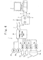
- FIG. 3 shows a fish robot and a control system according to the first embodiment of the present invention.
- a fish robot 1 in a water tank 2 is controlled by a manual control system 3 or an automatic control system 4.
- a switch 5 provided for the manual control system 3.
- An antenna 6 is provided for the manual control system 3 to transmit control radio wave 7 to the fish robot 1.
- the control radio wave 7 propagates through water in the water tank 2 and reaches the fish robot 1.
- the fish robot 1 operates in response to the control radio wave 7.
- the fish robot 1 sends echo radio wave 8.
- the echo radio wave 8 contains data transmitted by the control radio wave 7, and is used to check whether the control radio wave 7 is normally transmitted.
- the antenna 6 receives the echo radio wave 8.
- Fig. 4A and 4B show the structure of the fish robot 1.
- the fish robot 1 imitates the form of a coelacanth.
- the fish robot 1 has many fins, as coelacanth having many fins.
- Fig. 4A is a plan view of the outward appearance of the fish robot 1
- Fig. 4B is a side view of the outward appearance of the fish robot 1.
- the fish robot 1 is composed of a fish robot main unit 11.
- Two pectoral fins 12 1 and 12 2, two pelvic fins 13 1 and 13 2 , a first dorsal fin 14, a second dorsal fin 15, a first caudal fin 16 are connected with the fish robot main unit 11.
- a second caudal fin 17 is connected with a caudal portion of the fish robot main unit 11.
- a caudal fin 18 is connected with the second caudal fin 17.
- Each of the pectoral fins 12 1 and 12 2 , the pelvic fins 13 1 and 13 2 , the first dorsal fin 14, the second dorsal fin 15, the first caudal fin 16, the second caudal fin 17 and the caudal fin 18 is formed of a metal plate covered by a soft plastic film.
- Fig. 5A is a plan view showing the internal structure of the fish robot 1.
- the pectoral fins 12 1 and 12 2 are turnably connected with rotation axes 19 1 and 19 2 , respectively.
- the pectoral fin 12 1 is driven by a motor 20 1 to vibrate (or turn) around the rotation axis 19 1 as shown by the arrow 21 1 .
- the pectoral fin 12 2 is driven by a motor 20 2 to vibrate around the rotation axis 19 2 , as shown by the arrow 21 2 .
- the pelvic fins 13 1 and 13 2 are also turnably connected with rotation axes (not illustrated), respectively.
- the pelvic fins 13 1 and 13 2 are driven by motors 20 3 and 20 4 shown in Fig. 5B, respectively.
- the pelvic fins 13 1 and 13 2 are vibrated as shown by the arrows 22 1 and 22 2 in Fig. 5A, respectively.
- the second dorsal fin 15 and the first caudal fin 16 are turnably connected with rotation axes (not shown), respectively, in the same way.
- the second dorsal fin 15 and the first caudal fin 16 are driven by motors 20 5 and 20 6 shown in Fig. 5B, as shown by the arrows 23 and 24, respectively.
- the first dorsal fin 14 is fixed.
- the first dorsal fin 14 makes the posture of the fish robot 1 stable.
- the second caudal fin 17 contains a vibration fin 17 1 and a vibration fin 17 2 .
- One end of the vibration fin 17 1 is turnably connected with a rotation axis 25, as shown in Fig. 5A.
- the vibration fin 17 1 is driven by a motor 20 7 to vibrate around rotation axis 25 as shown by the arrow 26.
- the other end of the vibration fin 17 1 is connected with a rotation axis 27.
- One end of the vibration wing 17 2 is turnably connected with the rotation axis 27.
- the vibration fin 17 2 vibrates around the rotation axis 27 as shown by the arrow 26.
- the phase of the vibration of the vibration fin 17 1 and the phase of the vibration of the vibration fin 17 2 are shifted from each other and the vibration fin 17 2 operates in response to the operation of the vibration fin 17 1 . That is, the vibration fin 17 1 and the vibration fin 17 2 vibrate flexibly just like actual coelacanth.
- the constant S is set based on the movement and shape of an actual fish.
- the caudal fin 18 is connected with the second caudal fin 17.
- the caudal fin 18 turns around the rotation axis (not shown).
- the caudal fin 18 vibrates around the rotation axis (not shown) as shown by the arrow 26.
- the propulsion of the fish robot 1 is substantially generated only by the second caudal fin 17.
- the above-mentioned pectoral fins 12 1 and 12 2 , pelvic fin 13 1 and 13 2 , second dorsal fin 15, first caudal fin 16 and caudal fin 18 do not generate the propulsion of the fish robot 1 substantially.
- the posture of the fish robot 1 is controlled by all of the pectoral fins 12 1 and 12 2 , the pelvic fins 13 1 and 13 2 , the second dorsal fins 15, the first caudal fins 16, the second caudal fin 17 and the caudal fins 18. In this way, the behavior of the fish robot when the propulsion is generated and the posture is controlled is same as the actual coelacanth, resulting in the improvement of reality of the fish robot 1.
- each of the pectoral fins 12 1 and 12 2 , the pelvic fins 13 1 and 13 2 , the second dorsal fin 15, and the first caudal fin 16, and the caudal fin 18 vibrates around only one rotation axis, and the number of degrees of freedom is single.
- the pectoral fins 12 1 and 12 2 , the pelvic fins 13 1 and 13 2 , the second dorsal fin 15, the first caudal fin 16 and the caudal fin 18 are driven by the motors, respectively.
- the pectoral fins 12 1 and 12 2 , the pelvic fins 13 1 and 13 2 , the second dorsal fin 15, the first caudal fin 16 and the caudal fin 18 which are used only for the control of the posture of the fish robot 1 do not have to do always a complicated movement. Therefore, the number of degrees of freedom in each of the pectoral fins 12 1 and 12 2 , the pelvic fins 13 1 and 13 2, the second dorsal fin 15, the first caudal fin 16 and the caudal fin 18 is made single and a driving mechanical section can be made small in size.
- the fish robot 1 contains pumps 28 1 and 28 2 and tanks 29 1 and 29 2 as shown in Fig. 5B.
- the tank 29 1 is situated on the head of the fish robot 1.
- the tank 29 2 contains two portions which are located to sandwich the above-mentioned motors 20 3 to 20 8 .
- the pumps 28 1 and 28 2 injects and drains water into and from the tanks 29 1 and 29 2 .
- a position of the fish robot 1 in a gravity direction is controlled based on the quantity of water inside the tanks.
- the fish robot 1 sinks and floats into and from the gravity direction by injecting and draining water into and from the tanks 29 1 and 29 2 .
- the posture of the fish robot 1 is controlled. In this way, the provision of the plurality of the tanks 29 1 and 29 2 facilitates the control of the posture of the fish robot 1.
- the fish robot 1 contains a battery cell 31 as a power section (Fig. 5B).
- the battery cell 31 supplies the whole fish robot 1 with the power supply voltage.
- Fig. 6 shows the control system for instructing the operation of the fish robot 1.
- the fish robot 1 further contains a transmitting and receiving section 30.
- the transmitting and receiving section 30 receives the control radio wave 7 for instructing the operation of the fish robot 1.
- the control radio wave 7 contains a control process quantity of each of the motors 20 1 to 20 8 and the pumps 28 1 and 28 2 .
- the motors 20 1 to 20 8 and the pumps 28 1 and 28 2 operate based on the control radio wave 7.
- the frequency, phase and amplitude of the vibration of each of the above-mentioned pectoral fins 12 1 and 12 2, pelvic fins 13 1 and 13 2 , second dorsal fin 15, first caudal fin 16, second caudal fin 17 and caudal fin 18 are controlled based on the control radio wave 7.
- the frequency, phase and amplitude of vibration of the pectoral fins 12 1 and 12 2 , pelvic fins 13 1 and 13 2 , second dorsal fin 15, first caudal fin 16, first vibration fin 17 1 and second vibration fin 17 2 of the second caudal fin 17, and caudal fin 18 are determined for the fish robot 1 to move in a desired direction at a desired speed.
- "Propulsion System with Flexible/Rigid Oscillating Fin" (IEEE Journal of Oceanic Engineering vol. 20, No. 1, (1995), pp. 23-30) or a neural network described in Japanese Patent No. 3117310 may be used for the determination.
- the pectoral fins 12 1 and 12 2 , the pelvic fins 13 1 and 13 2 , the second dorsal fin 15, the first caudal fin 16, the second caudal fin 17 and the caudal fin 18 are controlled by the control system 5, and move flexibly just as the fins of actual coelacanth. Such a movement delights the person who sees the fish robot 1.
- the fish robot 1 is possible to move without being connected with a cable. Because the fish robot 1 can move without being connected with the cable, the reality of the fish robot 1 is improved.
- the transmitting and receiving section 30 sends data of the control process quantity of each of the motors 20 1 to 20 8 and the pumps 28 1 and 28 2 transmitted with the control radio wave 7, as echo radio wave 8.
- the control radio wave 7 to be propagated in underwater has a possibility to erroneously transfer the control process quantity.
- the echo radio wave 8 is used to confirm whether the control process quantity to each of the motors 20 1 to 20 8 , and the pumps 28 1 and 28 2 is right transmitted.
- the operation of the fish robot 1 is controlled by either of the manual control system 3 and the automatic control system 4.
- the fish robot 1 is controlled is switched by the switch 5.
- the manual control system 3 is used for the person who operates the fish robot 1 to instruct the operation of the fish robot 1.
- the control process quantity of each of the pumps 28 1 and 28 2 and the motors 20 1 to 20 8 contained in the fish robot 1 is determined in accordance with the operation of the manual control system 3 by the operation person.
- the control process quantity is transmitted to the fish robot 1 with the control radio wave 7.
- the automatic control system 4 When the automatic control system 4 is selected by the switch 5, the automatic control system 4 controls the fish robot 1 in accordance with algorithm defined by the software loaded thereinto.
- the automatic control system 4 determines the control process quantity of each of the pumps 28 1 and 28 2 and the motors 20 1 to 20 8 contained in the fish robot 1.
- the control process quantity is transferred to the manual control system 3 by a control signal 9 and then is transmitted to the fish robot 1 with the control radio wave 7 from the manual control system 3.
- the control radio wave 7 is a FM wave which is generated by carrying out frequency modulation (FM) to an electric signal with the amplitude proportional to the control process quantity. Because the control radio wave 7 is the FM wave, it is difficult for the control process quantity to be erroneously transmitted, even if the control radio wave 7 is attenuated with water.
- FM frequency modulation
- the control radio wave 7 is received by the transmitting and receiving section 30.
- the transmitting and receiving section 30 transfers the control process quantities of the pumps 28 1 and 28 2 and the motors 20 1 to 20 8 transmitted by the control radio wave 7 to the pumps 28 1 and 28 2 and the motors 20 1 to 20 8 , respectively.
- only the pumps 28 1 and 28 2 , and the motors 20 1 , 20 1 , 20 7 , and 20 8 are illustrated in Fig. 6.
- the pumps 28 1 and 28 2 inject and drain water into and from the tanks 29 1 and 29 2 in accordance with the transferred control process quantities.
- the motors 20 1 to 20 8 set displacement quantities in accordance with the transferred control process quantities.
- the motors 20 1 to 20 8 vibrate the pectoral fins 12 1 and 12 2 , the pelvic fins 13 1 and 13 2 , the first dorsal fin 14, the second dorsal fin 15, the first caudal fin 16, the first vibration fin 17 1 and the second the vibration fin 17 2 of the second caudal fin 17, respectively.
- the fish robot 1 is controlled by the manual control system 3 or the automatic control system 4.
- the transmitting and receiving section 30 transmits the control process quantity transmitted by the control radio wave 7 to the manual control system 3 with the echo radio wave 8.
- the manual control system 3 transfers the control process quantity transmitted by the echo radio wave 8 to the automatic control system 4 as an echo signal 10.
- the automatic control system 4 determines based on the echo signal 10, whether the control process quantity is transmitted right. Based on the determination, the automatic control system 4 sets a control process quantity of each of the pumps 28 1 and 28 2 and the motors 20 1 to 20 8 to be transmitted to the fish robot 1.
- a supersonic transmitter may be used instead of the antenna 6.
- a supersonic signal is used instead of the control radio wave 7 for controlling the fish robot 1.
- the control radio wave 7 is equal to or less than 100 MHz because the attenuation of the radio wave in the underwater becomes high as the frequency is increased.
- the present invention provides the fish robot realistically imitating fish which has a plurality of fins and a fin for the caudal portion.
- the underwater navigation body of the fish robot type imitating the fish which has a plurality of fins can be made more compact.
- an aquarium is provided in which the fish robots or fish robots similar to the above-mentioned fish robot swim in the water tank.
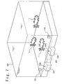
- Fig. 7 shows the structure of the aquarium.
- the aquarium has a water tank 102 in which water has been filled and a plurality of fish robots 1 are swimming in the water tank 102.
- the fish robot 1 imitates the form of fish like abyssal fish which it is difficult to acquire, ancient fish like coelacanth, or fish which it is impossible to acquire because it had become extinct, from the viewpoint of increase of amusement.
- the fish robot 1 imitates the form of the coelacanth.
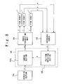
- Fig. 8 shows a control system of the fish robot in the second embodiment.
- the aquarium further contains a supersonic sensor 103, an operation unit 104, a control unit 105 and a radio wave transmitting unit 106.
- the supersonic sensor 103 is used to detect the position of the fish robot 1.
- a joystick 104a and a switch are provided for the operation unit 104.
- a visitor who visits the aquarium can instruct how the fish robot 1 swim by operating the joystick 104a.
- the switch 4b designates whether the fish robot 1 is controlled based on the operation of the joystick 104a or in accordance with the algorithm which is described in the software loaded into the control unit 105, like the first embodiment.
- the control unit 105 controls the fish robot 1 in accordance with the operation of the joystick 104a or the algorithm which is described in the loaded software based on the state of the switch 4b.
- the control unit 105 generates a signal for controlling the fish robot 1.
- the radio wave transmitting unit 106 sends the signal to the fish robot 1 with radio wave.
- the fish robot 1 generates a supersonic signal a.
- the supersonic signal a is used for the detection of the position of the fish robot 1.
- the supersonic sensor 103 receives and converts the supersonic signal a propagated in the underwater into an electric signal b.
- the electric signal b is transferred to the control unit 5.
- the operation unit 104 transmits to the control unit 105 an operation signal c1 to indicate the content of the operation accomplished by the joystick 104a. Also, the operation unit 104 outputs to the control unit 105 a specification signal c2 for specifying that the fish robot 1 should be controlled in accordance with which of the detected movement of the fish robot 1 and the operation of the joystick 104a, based on the state of the switch 4b.
- the control unit 105 contains a position detecting section 105 1 and a control section 105 2 .
- the position detecting section 105 1 detects the position of the fish robot 1 based on the electric signal b.
- the position of the fish robot 1 is notified to the control unit 105 2 by a position signal d.
- the control section 105 2 determines the movement of the fish robot 1. When it is designated based on the switch that the fish robot 1 is controlled in accordance with the operation of the joystick 104a, the control section 105 2 determines the movement of the fish robot 1 based on the content of the operation of the joystick 104a. When it is designated based on the switch that the fish robot 1 is controlled in accordance with the algorithm which is described in the software loaded into the control unit 105, the control section 105 2 determines the movement of the fish robot 1 while the control unit 105 refers to the position of the fish robot 1 in accordance with the algorithm. The control section 105 2 generates and outputs a control signal e for instructing the movement of the fish robot 1 to the radio wave transmitting unit 106. The radio wave transmitting unit 106 converts the control signal e into a control radio wave f and sends it to the fish robot 1.
- Fig. 9A is a plan view of the outward appearance of the fish robot 1.
- Fig. 9B is a side view of the outward appearance of the fish robot 1.
- the fish robot 1 contains a fish robot main unit 11.
- Two pectoral fins 12 1 and 12 2 , two pelvic fins 13 1 and 13 2 , the first dorsal fin 14, the second dorsal fin 15, the first caudal fin 16, the second caudal fin 17 are connected with the fish robot main unit 11.
- the caudal fin 18 is connected with the second caudal fin 17.
- the pectoral fins 12 1 and 12 2 , the pelvic fins 13 1 and 13 2 , the first dorsal fin 14, the second dorsal fin 15, the first caudal fin 16, the second caudal fin 17 and the caudal fin 18 are formed of plastic material with elasticity.
- the internal structure of the fish robot 1 in the second embodiment is same as in the first embodiment shown in Figs. 5A and 5B.
- the different point between the first and second embodiments is in that the fish robot 1 contains the supersonic transmitting units 31.
- the supersonic transmitting unit 31 sends the above-mentioned supersonic signal a.
- the supersonic signal a is used for the detection of the position of the fish robot 1, as described above.
- the fish robot 1 sinks and floats periodically.
- the sinking and floating movement of the fish robot is achieved by injecting and draining water into and from the tanks 29 1 and 29 2 by the pumps 28 1 and 28 2 .
- the fish robots 1 move to avoid crash.
- the distance ⁇ I is detected based on the positions of the fish robots 1 which are detected by the position detecting section 5 1 . As shown in Fig. 12, it is supposed that the distance ⁇ I between the fish robot 1 1 and the fish robot 1 2 becomes smaller than the predetermined distance L. In this case, the angles ⁇ 1 and ⁇ 2 different each other are set to the fish robots 1 1 and the fish robots 1 2 , respectively.
- the first vibration fin 17 1 and the second vibration fin 17 2 of the fish robot 1 1 are controlled to vibrate taking as a vibration center the angle ⁇ 1 from centerline 11a of the fish robot main unit 11, and the first vibration fin 17 1 and the second vibration fin 17 2 of the fish robot 1 2 are controlled to vibrate taking as a vibration center the angle ⁇ 2 from centerline 11a of the fish robot main unit 1 1 .
- the fish robot 1 1 and the fish robot 1 2 move in different directions and crash of the fish robots can be avoided.
- such a movement delights the visitor which sees the fish robots 1.
- the fish robot 1 moves in response to the operation of the joystick 104a.
- the control unit 105 controls the changes of the pectoral fins 12 1 and 12 2 , the pelvic fins 13 1 and 13 2 , the second dorsal fin 15, the first caudal fin 16, the second caudal fin 17 and the caudal fin 18 for the fish robot 1 to move in the specified direction.
- the fish robot 1 moves in the specified direction in accordance with the operation of the joystick of 104a.
- the operation person who operates the joystick 104a can enjoy that the fish robot 1 moves in accordance with the operation of the joystick 104a.
- the movement of the fish robot 1 delights the person seeing it.
- the entertainment of the aquarium in this embodiment is high and the visitor collecting effect can look forward to it.
- a supersonic transmitting unit may be used instead of the radio wave transmitting unit 106.
- a supersonic signal is used instead of the control radio wave f for controlling the fish robot 1.
- the attenuation percentage of the radio wave in the underwater is about 10 dB/m when the frequency is 100Mz. This means that the communication between two in the radio wave is sufficiently possible, if the distance between the two is within 10 m. Therefore, the control of the fish robot 1 is carried out while using the control radio wave f and the quick signal processing inside the fish robot 1 is attempted.
- control radio wave f is generated by FM-modulating the control signal e. It is difficult for the control radio wave f as an FM wave to undergo attenuation influence.
- amusement facilities where the high visitor collection effect is expected can be provided in the present invention.
Landscapes
- Engineering & Computer Science (AREA)
- Mechanical Engineering (AREA)
- Ocean & Marine Engineering (AREA)
- Aviation & Aerospace Engineering (AREA)
- Computer Networks & Wireless Communication (AREA)
- Chemical & Material Sciences (AREA)
- Combustion & Propulsion (AREA)
- Toys (AREA)
Abstract
A fish-type underwater navigation body includes a caudal turning section provided for a caudal section of a main unit, a pair of first side turning sections provided in front lower sections of the main unit, and a pair of second side turning sections provided in side lower sections between a center section and the caudal section in the main unit. The fish-type underwater navigation body gets propulsion by turning the caudal turning section. Also, the pair of first side turning sections, the pair of second side turning sections and the caudal turning section function for attitude control of the fish-type underwater navigation body. <IMAGE>
Description
The present invention is relates to a fish-type
underwater navigation body, a control system
of the fish-type underwater navigation body, and
an aquarium to exhibit a fish-type underwater
navigation body.
A first conventional example of an
underwater navigation body is known in Japan Laid
Open Patent Application (JP-A-Heisei 11-152085),
in which a wing is vibrated like the fin of a
fish for propulsion and steering. The first
conventional example of the underwater navigation
body is composed of wing portions 201a and 201b,
as shown in Fig. 1. The wing portions 201a and
201b are connected in series. The wing portions
201a and 201b are turned around rotation axes 204
and 205, respectively. The vibration of the wing
portions 201a and 201b is controlled in
cooperation to each other, and the wing portions
201a and 201b operate flexibly like a caudal fin
of the fish as a whole. Thus, the first
conventional example of the underwater navigation
body acquires propulsion. Also, the vibration of
the wing portions 201a and 201b is controlled in
the cooperation to each other and the steering is
carried out. The first conventional example of
the underwater navigation body contains a single
tank 207. The up and down control of the
underwater navigation body is carried out by
water filling and drainage to the tank 207.
A second conventional example of the
underwater navigation body is known in the above-mentioned
reference. The second conventional
example of the underwater navigation body is
composed of a plurality of vibration wings 121 on
the both edges of a main unit 222, as shown in
Fig. 2. The vibration wings 221 are driven by a
first actuator 224 to rotate around a vertical
axis 225. In addition, the vibration wings 221
are driven by a second actuator 223 to turn
around an axis 226. Thus, an angle is adjusted.
In the second conventional example of the
underwater navigation body, the propulsion and
steering are carried out by the plurality of
vibration wings 221. Either of the vibration
wings 221 contributes both of the propulsion and
the steering.
One of the application fields of such an
underwater navigation body includes a fish robot
(artificial fish). A lot of people expect new
amusement facilities for their leisure. Such a
fish robot has a high entertainment and a high
needs as the new amusement facilities.
However, the amusement facilities in which
the plurality of fish robots swim while imitating
ecology in actual undersea do not exist
conventionally, and the amusement facilities can
be expected in collection of many visitors.
Especially, the visitor collecting is effected in
the amusement facilities where an ancient fish
which does not exist like coelacanth swims.
Therefore, an object of the present
invention is to provide a fish-type underwater
navigation body like a fish robot imitating a
fish having a plurality of fins such as pectoral
fins, pelvic fins and a caudal fin.
Another object of the present invention is
to provide a fish-type underwater navigation body
like a fish robot which is stable in the attitude
while swimming to generate propulsion.
Another object of the present invention is
to provide a fish-type underwater navigation body
like a fish robot which can be controlled
externally.
Another object of the present invention is
to provide a fish-type underwater navigation body
control system which controls a fish-type
underwater navigation body like a fish robot
externally.
Another object of the present invention is
to realize an aquarium in which a fish-type
underwater navigation body like a fish robot
swims, and which is an amusement facilities
having a high visitor collecting effect.
In a first aspect of the present invention,
a fish-type underwater navigation body includes a
caudal turning section provided for a caudal
section of a main unit, a pair of first side
turning sections provided in front lower sections
of the main unit, and a pair of second side
turning sections provided in side lower sections
between a center section and the caudal section
in the main unit.
Here, the fish-type underwater navigation
body generates propulsion by turning the caudal
turning section. Also, the pair of first side
turning sections, the pair of second side turning
sections and the caudal turning section function
for attitude control of the fish-type underwater
navigation body.
Also, the fish-type underwater navigation
body may further include a dorsal turning section
provided for an upper section between the center
section and the caudal section in the main unit
and functions for attitude control of the fish-type
underwater navigation body. Also, the fish-type
underwater navigation body may further
include another caudal turning section provided
in the lower section between the center section
and the caudal section in the main unit and
functions for attitude control of the fish-type
underwater navigation body.
Also, the caudal turning section of the
fish-type underwater navigation body may include
a first caudal turning section, and a second
caudal turning section connected with the first
caudal turning section. The first caudal turning
section turns in response to a turning operation
of the second caudal turning section so as to
realize an operation similar to a fish. It is
desirable that the turning frequency of the
caudal turning section is determined based on a
speed of the fish-type underwater navigation body
and a width of the fish-type underwater
navigation body in a direction perpendicular to a
direction of movement of the fish-type underwater
navigation body.
Also, the fish-type underwater navigation
body may further include a flotage tank section,
and movement of the fish-type underwater
navigation body upwardly and downwardly is
controlled based on a quantity of water in the
flotage tank section. For smooth flotage and
sinking operation, it is desirable that the
flotage tank section includes a front flotage
tank section and a rear flotage tank section.
Also, for valance in the left and right
directions, it is desirable that the rear flotage
tank section includes a pair of flotage tank
sections.
Also, the fish-type underwater navigation
body may further include a driving section which
drives the caudal turning section, the pair of
first side turning sections and the pair of
second side turning sections independently, a
receiving section which receives a radio wave
instruction signal propagated in underwater, and
a control section which controls the driving
section based on the radio wave instruction
signal. In this way, it is possible to control
the fish-type underwater navigation body. At the
time, it is desirable that a frequency of the
radio wave instruction signal is equal to or less
than 100 MHz, in consideration of the attenuation
of the radio wave instruction signal. Also, it is
desirable that the fish-type underwater
navigation body further includes a transmitting
section which replies a content of the radio wave
instruction signal when the radio wave
instruction signal is received. Thus, it is
possible to determine whether the instruction
reached right.
In another aspect of the present invention,
a fish-type underwater navigation body control
system includes the above fish-type underwater
navigation body, and a control unit which
transmits a radio wave instruction signal to the
fish-type underwater navigation body through
underwater. The fish-type underwater navigation
body further includes a driving section which
drives the pair of first side turning sections,
the a pair of second side turning sections and
the caudal turning section independently, a
receiving section which receives the radio wave
instruction signal propagated in the underwater,
and a drive control unit which controls the
driving section based on the radio wave
instruction signal.
In this case, it is desirable that the
frequency of the radio wave instruction signal is
equal to or less than 100 MHz.
Also, the control unit may further include
an operation unit, and a transmitting section
which outputs the radio wave instruction signal
in the underwater based on an operation of the
operation unit.
Also, the fish-type underwater navigation
body may include a supersonic transmission
section. In this case, the fish-type underwater
navigation body control system further includes a
position detecting section which detects the
position of the fish-type underwater navigation
body based on supersonic signals outputted from
the supersonic transmission sections of the
plurality of fish-type underwater navigation
bodies. The control unit outputs the radio wave
instruction signal to one of the plurality of
fish-type underwater navigation bodies for
avoidance of collision with another of the
plurality of fish-type underwater navigation
bodies based on the position detected by the
position detecting section.
Also, when the plurality of the fish-type
underwater navigation bodies swim, movement of
one of the plurality of fish-type underwater
navigation bodies is desirably determined based
on the radio wave instruction signal generated
based on the position detected by the position
detecting section, for prevention of collision.
In another aspect of the present invention,
an aquarium includes a water tank and at least
one of the fish-type underwater navigation
bodies. The fish-type underwater navigation body
swims in the water tank.
Here, an outward appearance of the main
unit of the fish-type underwater navigation body
imitates coelacanth.
Also, a plurality of the fish-type
underwater navigation body swim in the water
tank, and each of the plurality of fish-type
underwater navigation bodies move along closed
loops, respectively. Also, each of the plurality
of fish-type underwater navigation bodies sinks
and floats periodically in a gravity direction.
Also, the aquarium may further include a
control unit which transmits a radio wave
instruction signal to the fish-type underwater
navigation body through underwater. The fish-type
underwater navigation body includes a driving
section which drives the pair of first side
turning sections, the pair of second side turning
sections and the caudal turning section
independently; a receiving section which receives
the radio wave instruction signal propagated in
the underwater; and a drive control unit which
controls the driving section based on the radio
wave instruction signal. The control unit further
includes an operation section; and a transmitting
section which outputs the radio wave instruction
signal into the underwater based on an operation
of the operation section.
Hereinafter, an underwater navigation body
like a fish robot of the present invention will
be described in detail with reference to the
attached drawings.
Fig. 3 shows a fish robot and a control
system according to the first embodiment of the
present invention. A fish robot 1 in a water tank
2 is controlled by a manual control system 3 or
an automatic control system 4. By which of the
manual control system 3 and the automatic control
system 4 the fish robot 1 is controlled is
switched by a switch 5 provided for the manual
control system 3.
An antenna 6 is provided for the manual
control system 3 to transmit control radio wave 7
to the fish robot 1. The control radio wave 7
propagates through water in the water tank 2 and
reaches the fish robot 1. The fish robot 1
operates in response to the control radio wave 7.
Also, the fish robot 1 sends echo radio wave 8.
The echo radio wave 8 contains data transmitted
by the control radio wave 7, and is used to check
whether the control radio wave 7 is normally
transmitted. The antenna 6 receives the echo
radio wave 8.
Fig. 4A and 4B show the structure of the
fish robot 1. The fish robot 1 imitates the form
of a coelacanth. The fish robot 1 has many fins,
as coelacanth having many fins.
Fig. 4A is a plan view of the outward
appearance of the fish robot 1, and Fig. 4B is a
side view of the outward appearance of the fish
robot 1. The fish robot 1 is composed of a fish
robot main unit 11. Two pectoral fins 121 and
122, two pelvic fins 131 and 132, a first dorsal
fin 14, a second dorsal fin 15, a first caudal
fin 16 are connected with the fish robot main
unit 11. A second caudal fin 17 is connected with
a caudal portion of the fish robot main unit 11.
A caudal fin 18 is connected with the second
caudal fin 17. Each of the pectoral fins 121 and
122, the pelvic fins 131 and 132, the first dorsal
fin 14, the second dorsal fin 15, the first
caudal fin 16, the second caudal fin 17 and the
caudal fin 18 is formed of a metal plate covered
by a soft plastic film.
Fig. 5A is a plan view showing the internal
structure of the fish robot 1. As shown in Fig.
5A, the pectoral fins 121 and 122 are turnably
connected with rotation axes 191 and 192,
respectively. The pectoral fin 121 is driven by a
motor 201 to vibrate (or turn) around the rotation
axis 191 as shown by the arrow 211. The pectoral
fin 122 is driven by a motor 202 to vibrate around
the rotation axis 192, as shown by the arrow 212.
Similarly, the pelvic fins 131 and 132 are
also turnably connected with rotation axes (not
illustrated), respectively. The pelvic fins 131
and 132 are driven by motors 203 and 204 shown in
Fig. 5B, respectively. The pelvic fins 131 and
132 are vibrated as shown by the arrows 221 and
222 in Fig. 5A, respectively.
Moreover, the second dorsal fin 15 and the
first caudal fin 16 are turnably connected with
rotation axes (not shown), respectively, in the
same way. The second dorsal fin 15 and the first
caudal fin 16 are driven by motors 205 and 206
shown in Fig. 5B, as shown by the arrows 23 and
24, respectively.
The first dorsal fin 14 is fixed. The
first dorsal fin 14 makes the posture of the fish
robot 1 stable.
The second caudal fin 17 contains a
vibration fin 171 and a vibration fin 172. One
end of the vibration fin 171 is turnably connected
with a rotation axis 25, as shown in Fig. 5A. The
vibration fin 171 is driven by a motor 207 to
vibrate around rotation axis 25 as shown by the
arrow 26. The other end of the vibration fin 171
is connected with a rotation axis 27. One end of
the vibration wing 172 is turnably connected with
the rotation axis 27. The vibration fin 172
vibrates around the rotation axis 27 as shown by
the arrow 26.
The phase of the vibration of the vibration
fin 171 and the phase of the vibration of the
vibration fin 172 are shifted from each other and
the vibration fin 172 operates in response to the
operation of the vibration fin 171. That is, the
vibration fin 171 and the vibration fin 172
vibrate flexibly just like actual coelacanth.
The frequency f of the vibration by the
vibration fin 171 and the vibration fin 172 is
expressed by the following equation:
f = S·(U/D)
where D is the width D of the fish robot main
unit 11 (see Fig. 2A), U is the speed of the fish
robot 1, and S is a constant. The constant S is
set based on the movement and shape of an actual
fish. By determining the frequency f in this way,
the second caudal fin 17 vibrates just like
genuine fish.
As shown in Fig. 5B, the caudal fin 18 is
connected with the second caudal fin 17. The
caudal fin 18 turns around the rotation axis (not
shown). The caudal fin 18 vibrates around the
rotation axis (not shown) as shown by the arrow
26.
The propulsion of the fish robot 1 is
substantially generated only by the second caudal
fin 17. The above-mentioned pectoral fins 121 and
122, pelvic fin 131 and 132, second dorsal fin 15,
first caudal fin 16 and caudal fin 18 do not
generate the propulsion of the fish robot 1
substantially. On the other hand, the posture of
the fish robot 1 is controlled by all of the
pectoral fins 121 and 122, the pelvic fins 131 and
132, the second dorsal fins 15, the first caudal
fins 16, the second caudal fin 17 and the caudal
fins 18. In this way, the behavior of the fish
robot when the propulsion is generated and the
posture is controlled is same as the actual
coelacanth, resulting in the improvement of
reality of the fish robot 1.
Here, each of the pectoral fins 121 and 122,
the pelvic fins 131 and 132, the second dorsal fin
15, and the first caudal fin 16, and the caudal
fin 18 vibrates around only one rotation axis,
and the number of degrees of freedom is single.
The pectoral fins 121 and 122, the pelvic fins 131
and 132, the second dorsal fin 15, the first
caudal fin 16 and the caudal fin 18 are driven by
the motors, respectively. The pectoral fins 121
and 122, the pelvic fins 131 and 132, the second
dorsal fin 15, the first caudal fin 16 and the
caudal fin 18 which are used only for the control
of the posture of the fish robot 1 do not have to
do always a complicated movement. Therefore, the
number of degrees of freedom in each of the
pectoral fins 121 and 122, the pelvic fins 131 and
132, the second dorsal fin 15, the first caudal
fin 16 and the caudal fin 18 is made single and a
driving mechanical section can be made small in
size.
Moreover; the fish robot 1 contains pumps
281 and 282 and tanks 291 and 292 as shown in Fig.
5B. The tank 291 is situated on the head of the
fish robot 1. The tank 292 contains two portions
which are located to sandwich the above-mentioned
motors 203 to 208.
The pumps 281 and 282 injects and drains
water into and from the tanks 291 and 292. A
position of the fish robot 1 in a gravity
direction is controlled based on the quantity of
water inside the tanks. The fish robot 1 sinks
and floats into and from the gravity direction by
injecting and draining water into and from the
tanks 291 and 292. Thus, the posture of the fish
robot 1 is controlled. In this way, the provision
of the plurality of the tanks 291 and 292
facilitates the control of the posture of the
fish robot 1.
Moreover, the fish robot 1 contains a
battery cell 31 as a power section (Fig. 5B). The
battery cell 31 supplies the whole fish robot 1
with the power supply voltage.
Fig. 6 shows the control system for
instructing the operation of the fish robot 1.
Referring to Fig. 6, the fish robot 1 further
contains a transmitting and receiving section 30.
The transmitting and receiving section 30
receives the control radio wave 7 for instructing
the operation of the fish robot 1. The control
radio wave 7 contains a control process quantity
of each of the motors 201 to 208 and the pumps 281
and 282. The motors 201 to 208 and the pumps 281
and 282 operate based on the control radio wave 7.
That is, the frequency, phase and amplitude of
the vibration of each of the above-mentioned
pectoral fins 121 and 122, pelvic fins 131 and 132,
second dorsal fin 15, first caudal fin 16, second
caudal fin 17 and caudal fin 18 are controlled
based on the control radio wave 7.
The frequency, phase and amplitude of
vibration of the pectoral fins 121 and 122, pelvic
fins 131 and 132, second dorsal fin 15, first
caudal fin 16, first vibration fin 171 and second
vibration fin 172 of the second caudal fin 17, and
caudal fin 18 are determined for the fish robot 1
to move in a desired direction at a desired
speed. "Propulsion System with Flexible/Rigid
Oscillating Fin", (IEEE Journal of Oceanic
Engineering vol. 20, No. 1, (1995), pp. 23-30) or
a neural network described in Japanese Patent No.
3117310 may be used for the determination. As a
result, the pectoral fins 121 and 122, the pelvic
fins 131 and 132, the second dorsal fin 15, the
first caudal fin 16, the second caudal fin 17 and
the caudal fin 18 are controlled by the control
system 5, and move flexibly just as the fins of
actual coelacanth. Such a movement delights the
person who sees the fish robot 1.
In this way, the fish robot 1 is possible
to move without being connected with a cable.
Because the fish robot 1 can move without being
connected with the cable, the reality of the fish
robot 1 is improved.
Moreover, the transmitting and receiving
section 30 sends data of the control process
quantity of each of the motors 201 to 208 and the
pumps 281 and 282 transmitted with the control
radio wave 7, as echo radio wave 8. The control
radio wave 7 to be propagated in underwater has a
possibility to erroneously transfer the control
process quantity. The echo radio wave 8 is used
to confirm whether the control process quantity
to each of the motors 201 to 208, and the pumps
281 and 282 is right transmitted.
As mentioned above, the operation of the
fish robot 1 is controlled by either of the
manual control system 3 and the automatic control
system 4. By which of the manual control system 3
and automatic control system 4, the fish robot 1
is controlled is switched by the switch 5.
The manual control system 3 is used for the
person who operates the fish robot 1 to instruct
the operation of the fish robot 1. When the
manual control system 3 is selected by the switch
5, the control process quantity of each of the
pumps 281 and 282 and the motors 201 to 208
contained in the fish robot 1 is determined in
accordance with the operation of the manual
control system 3 by the operation person. The
control process quantity is transmitted to the
fish robot 1 with the control radio wave 7.
When the automatic control system 4 is
selected by the switch 5, the automatic control
system 4 controls the fish robot 1 in accordance
with algorithm defined by the software loaded
thereinto. The automatic control system 4
determines the control process quantity of each
of the pumps 281 and 282 and the motors 201 to 208
contained in the fish robot 1. The control
process quantity is transferred to the manual
control system 3 by a control signal 9 and then
is transmitted to the fish robot 1 with the
control radio wave 7 from the manual control
system 3.
The control radio wave 7 is a FM wave which
is generated by carrying out frequency modulation
(FM) to an electric signal with the amplitude
proportional to the control process quantity.
Because the control radio wave 7 is the FM wave,
it is difficult for the control process quantity
to be erroneously transmitted, even if the
control radio wave 7 is attenuated with water.
The control radio wave 7 is received by the
transmitting and receiving section 30. The
transmitting and receiving section 30 transfers
the control process quantities of the pumps 281
and 282 and the motors 201 to 208 transmitted by
the control radio wave 7 to the pumps 281 and 282
and the motors 201 to 208, respectively. However,
only the pumps 281 and 282, and the motors 201,
201, 207, and 208 are illustrated in Fig. 6. The
pumps 281 and 282 inject and drain water into and
from the tanks 291 and 292 in accordance with the
transferred control process quantities. The
motors 201 to 208 set displacement quantities in
accordance with the transferred control process
quantities. The motors 201 to 208 vibrate the
pectoral fins 121 and 122, the pelvic fins 131 and
132, the first dorsal fin 14, the second dorsal
fin 15, the first caudal fin 16, the first
vibration fin 171 and the second the vibration fin
172 of the second caudal fin 17, respectively. In
this way, the fish robot 1 is controlled by the
manual control system 3 or the automatic control
system 4.
Moreover, the transmitting and receiving
section 30 transmits the control process quantity
transmitted by the control radio wave 7 to the
manual control system 3 with the echo radio wave
8. The manual control system 3 transfers the
control process quantity transmitted by the echo
radio wave 8 to the automatic control system 4 as
an echo signal 10. The automatic control system 4
determines based on the echo signal 10, whether
the control process quantity is transmitted
right. Based on the determination, the automatic
control system 4 sets a control process quantity
of each of the pumps 281 and 282 and the motors
201 to 208 to be transmitted to the fish robot 1.
It should be noted that in this embodiment,
a supersonic transmitter may be used instead of
the antenna 6. In this case, instead of the
control radio wave 7 for controlling the fish
robot 1, a supersonic signal is used. However, it
is desirable to control the fish robot 1 using
the control radio wave 7 like this embodiment,
from the viewpoint of the high-speed signal
processing in the fish robot 1.
It is generally thought that it is
difficult to transmit a signal through the
underwater using the radio wave because the
attenuation of the radio wave in the underwater
is large. For this reason, when the signal is
transmitted through the underwater, a supersonic
signal is often used. However, it is actually
possible to transmit a signal through the
underwater with the radio wave. This is because
the attenuation of the radio wave in the
underwater is about 10 dB/m when the frequency is
100Mz. Therefore, the distance between two points
is within 10 m, the communication between the two
points is sufficiently possible using the radio
wave. It should be noted that it is desirable
that the control radio wave 7 is equal to or less
than 100 MHz because the attenuation of the radio
wave in the underwater becomes high as the
frequency is increased.
The present invention provides the fish
robot realistically imitating fish which has a
plurality of fins and a fin for the caudal
portion.
Also, according to the present invention,
the underwater navigation body of the fish robot
type imitating the fish which has a plurality of
fins can be made more compact.
Next, the second embodiment of the present
invention will be described. In the second
embodiment, an aquarium is provided in which the
fish robots or fish robots similar to the above-mentioned
fish robot swim in the water tank.
Fig. 7 shows the structure of the aquarium.
The aquarium has a water tank 102 in which water
has been filled and a plurality of fish robots 1
are swimming in the water tank 102.
It is desirable that the fish robot 1
imitates the form of fish like abyssal fish which
it is difficult to acquire, ancient fish like
coelacanth, or fish which it is impossible to
acquire because it had become extinct, from the
viewpoint of increase of amusement. In this
embodiment, the fish robot 1 imitates the form of
the coelacanth.
Fig. 8 shows a control system of the fish
robot in the second embodiment. The aquarium
further contains a supersonic sensor 103, an
operation unit 104, a control unit 105 and a
radio wave transmitting unit 106. The supersonic
sensor 103 is used to detect the position of the
fish robot 1. A joystick 104a and a switch (not
shown) are provided for the operation unit 104. A
visitor who visits the aquarium can instruct how
the fish robot 1 swim by operating the joystick
104a. The switch 4b designates whether the fish
robot 1 is controlled based on the operation of
the joystick 104a or in accordance with the
algorithm which is described in the software
loaded into the control unit 105, like the first
embodiment.
The control unit 105 controls the fish
robot 1 in accordance with the operation of the
joystick 104a or the algorithm which is described
in the loaded software based on the state of the
switch 4b. The control unit 105 generates a
signal for controlling the fish robot 1. The
radio wave transmitting unit 106 sends the signal
to the fish robot 1 with radio wave.
The fish robot 1 generates a supersonic
signal a. The supersonic signal a is used for the
detection of the position of the fish robot 1.
The supersonic sensor 103 receives and converts
the supersonic signal a propagated in the
underwater into an electric signal b. The
electric signal b is transferred to the control
unit 5.
On the other hand, the operation unit 104
transmits to the control unit 105 an operation
signal c1 to indicate the content of the
operation accomplished by the joystick 104a.
Also, the operation unit 104 outputs to the
control unit 105 a specification signal c2 for
specifying that the fish robot 1 should be
controlled in accordance with which of the
detected movement of the fish robot 1 and the
operation of the joystick 104a, based on the
state of the switch 4b.
The control unit 105 contains a position
detecting section 1051 and a control section 1052.
The position detecting section 1051 detects the
position of the fish robot 1 based on the
electric signal b. The position of the fish robot
1 is notified to the control unit 1052 by a
position signal d.
The control section 1052 determines the
movement of the fish robot 1. When it is
designated based on the switch that the fish
robot 1 is controlled in accordance with the
operation of the joystick 104a, the control
section 1052 determines the movement of the fish
robot 1 based on the content of the operation of
the joystick 104a. When it is designated based on
the switch that the fish robot 1 is controlled in
accordance with the algorithm which is described
in the software loaded into the control unit 105,
the control section 1052 determines the movement
of the fish robot 1 while the control unit 105
refers to the position of the fish robot 1 in
accordance with the algorithm. The control
section 1052 generates and outputs a control
signal e for instructing the movement of the fish
robot 1 to the radio wave transmitting unit 106.
The radio wave transmitting unit 106 converts the
control signal e into a control radio wave f and
sends it to the fish robot 1.
Next, the structure of the fish robot 1
will be described. Fig. 9A is a plan view of the
outward appearance of the fish robot 1. Fig. 9B
is a side view of the outward appearance of the
fish robot 1. The fish robot 1 contains a fish
robot main unit 11. Two pectoral fins 121 and
122, two pelvic fins 131 and 132, the first dorsal
fin 14, the second dorsal fin 15, the first
caudal fin 16, the second caudal fin 17 are
connected with the fish robot main unit 11. The
caudal fin 18 is connected with the second caudal
fin 17. The pectoral fins 121 and 122, the pelvic
fins 131 and 132, the first dorsal fin 14, the
second dorsal fin 15, the first caudal fin 16,
the second caudal fin 17 and the caudal fin 18
are formed of plastic material with elasticity.
The internal structure of the fish robot 1
in the second embodiment is same as in the first
embodiment shown in Figs. 5A and 5B. The
different point between the first and second
embodiments is in that the fish robot 1 contains
the supersonic transmitting units 31. The
supersonic transmitting unit 31 sends the above-mentioned
supersonic signal a. The supersonic
signal a is used for the detection of the
position of the fish robot 1, as described above.
Next, the movement of the fish robot 1 will
be described with reference to Fig. 10A and 10B.
When it is designated based on the switch that
the fish robot 1 is controlled in accordance with
the algorithm which is described to the software
loaded into the control unit 105, an instruction
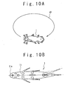
is given for the fish robot 1 to swim along a
closed loop 41, as shown in Fig. 10A. That is,
the instruction is given to the fish robot 1 to
vibrate the first vibration fin 171 and the second
vibration fins 172 of the second caudal fin 17,
such that the fish robot 1 swims to have a
predetermined angle from the centerline 11a of
the fish robot main unit 11, as shown in Fig.
10B. When the first vibration fin 171 and the
second vibration fin 172 are vibrated to have the
predetermined angle with respect to the
centerline 11a, the fish robot 1 goes around
along the closed loop 41.
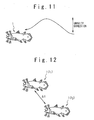
At this time, as shown in Fig. 11, the fish
robot 1 sinks and floats periodically. Through
the periodically sinking and floating movement of
the fish robot 1, the movement of the fish robot
1 gets to be nearer the movement of the actual
fish and the reality increases. The sinking and
floating movement of the fish robot is achieved
by injecting and draining water into and from the
tanks 291 and 292 by the pumps 281 and 282.
It should be noted that when the distance
ΔI between the fish robots 1 becomes smaller than
a predetermined distance L, the fish robots 1
move to avoid crash. The distance ΔI is detected
based on the positions of the fish robots 1 which
are detected by the position detecting section 51.
As shown in Fig. 12, it is supposed that the
distance ΔI between the fish robot 11 and the fish
robot 12 becomes smaller than the predetermined
distance L. In this case, the angles 1 and 2
different each other are set to the fish robots 11
and the fish robots 12, respectively. The first
vibration fin 171 and the second vibration fin 172
of the fish robot 11 are controlled to vibrate
taking as a vibration center the angle 1 from
centerline 11a of the fish robot main unit 11,
and the first vibration fin 171 and the second
vibration fin 172 of the fish robot 12 are
controlled to vibrate taking as a vibration
center the angle 2 from centerline 11a of the
fish robot main unit 11. Thus, the fish robot 11
and the fish robot 12 move in different directions
and crash of the fish robots can be avoided.
Moreover, such a movement delights the visitor
which sees the fish robots 1.
On the other hand, when it is specified
that the fish robot 1 is controlled in accordance
with the operation of the joystick 104a by the
switch, as mentioned above, the fish robot 1
moves in response to the operation of the
joystick 104a. When the direction in which the
fish robot 1 should move is set by the joystick
104a, the control unit 105 controls the changes
of the pectoral fins 121 and 122, the pelvic fins
131 and 132, the second dorsal fin 15, the first
caudal fin 16, the second caudal fin 17 and the
caudal fin 18 for the fish robot 1 to move in the
specified direction. Thus, the fish robot 1 moves
in the specified direction in accordance with the
operation of the joystick of 104a. The operation
person who operates the joystick 104a can enjoy
that the fish robot 1 moves in accordance with
the operation of the joystick 104a.
In this way, the movement of the fish robot
1 delights the person seeing it. The
entertainment of the aquarium in this embodiment
is high and the visitor collecting effect can
look forward to it.
It should be noted that in this embodiment,
a supersonic transmitting unit may be used
instead of the radio wave transmitting unit 106.
In this case, instead of the control radio wave f
for controlling the fish robot 1, a supersonic
signal is used. However, it is desirable to
control the fish robots 1 using the control radio
wave f like this embodiment from the viewpoint of
a quick signal processing inside the fish robot 1. It is considered generally that it is
difficult to transmit a signal in the underwater
with the radio wave, because the attenuation
percentage of the radio wave in the underwater is
large. Therefore, when a signal is transmitted in
the underwater, a supersonic signal is often
used. However, it is actually possible to
transmit a signal in the radio wave to be
propagated in underwater. The reason is that the
attenuation percentage of the radio wave in the
underwater is about 10 dB/m when the frequency is
100Mz. This means that the communication between
two in the radio wave is sufficiently possible,
if the distance between the two is within 10 m.
Therefore, the control of the fish robot 1 is
carried out while using the control radio wave f
and the quick signal processing inside the fish
robot 1 is attempted.
It is desirable that the control radio wave
f is generated by FM-modulating the control
signal e. It is difficult for the control radio
wave f as an FM wave to undergo attenuation
influence.
The amusement facilities where the high
visitor collection effect is expected can be
provided in the present invention.
Claims (23)
- A fish-type underwater navigation body comprising:a caudal turning section provided for a caudal section of a main unit;a pair of first side turning sections provided in front lower sections of said main unit; anda pair of second side turning sections provided in side lower sections between a center section and the caudal section in said main unit.
- The fish-type underwater navigation body according to claim 1, wherein propulsion is generated by turning said caudal turning section.
- The fish-type underwater navigation body according to claim 1 or 2, wherein said pair of first side turning sections, said pair of second side turning sections and said caudal turning section function for attitude control of said fish-type underwater navigation body.
- The fish-type underwater navigation body according to any of claims 1 to 3, further comprising:a dorsal turning section provided for an upper section between the center section and the caudal section in said main unit and functioning for attitude control of said fish-type underwater navigation body.
- The fish-type underwater navigation body according to any of claims 1 to 4, further comprising:another caudal turning section provided in a lower section between the center section and the caudal section in said main unit and functioning for attitude control of said fish-type underwater navigation body.
- The fish-type underwater navigation body according to any of claims 1 to 6, wherein said caudal turning section comprises:a first caudal turning section; anda second caudal turning section connected with said first caudal turning section, andsaid first caudal turning section turns in response to a turning operation of said second caudal turning section.
- The fish-type underwater navigation body according to claim 6, wherein a turning frequency of said caudal turning section is determined based on a speed of said fish-type underwater navigation body and a width of said fish-type underwater navigation body in a direction perpendicular to a direction of movement of said fish-type underwater navigation body.
- The fish-type underwater navigation body according to any of claims 1 to 7, further comprising:wherein movement of said fish-type underwater navigation body upwardly and downwardly is controlled based on a quantity of water in said flotage tank section.a flotage tank section, and
- The fish-type underwater navigation body according to claim 8, wherein said flotage tank section comprises:a front flotage tank section and a pair of rear flotage tank sections.
- The fish-type underwater navigation body according to any of claims 1 to 9, further comprising:a driving section which drives said caudal turning section, said pair of first side turning sections and said pair of second side turning sections independently;a receiving section which receives a radio wave instruction signal propagated in underwater; anda control section which controls said driving section based on said radio wave instruction signal.
- The fish-type underwater navigation body according to claim 10, wherein a frequency of said radio wave instruction signal is equal to or less than 100 MHz.
- The fish-type underwater navigation body according to claim 10 or 11, further comprising:a transmitting section which replies a content of said radio wave instruction signal when said radio wave instruction signal is received.
- A fish-type underwater navigation body control system comprising:wherein said fish-type underwater navigation body further comprises:said fish-type underwater navigation body according to any of claims 1 to 12; anda control unit which transmits a radio wave instruction signal to said fish-type underwater navigation body through underwater,a driving section which drives said pair of first side turning section, said pair of second side turning sections and said caudal turning section independently;a receiving section which receives said radio wave instruction signal propagated in the underwater; anda drive control unit which controls said driving section based on said radio wave instruction signal.
- The fish-type underwater navigation body control system according to claim 13, wherein a frequency of said radio wave instruction signal is equal to or less than 100 MHz.
- The fish-type underwater navigation body control system according to claim 13 or 14,
wherein said control unit comprises:an operation unit; anda transmitting unit which outputs said radio wave instruction signal in the underwater based on an operation of said operation unit. - The fish-type underwater navigation body control system according to any of claims 13 to 15, wherein said fish-type underwater navigation body comprises:a supersonic transmitting section,said fish-type underwater navigation body control system further comprises:a position detecting section which detects a position of each of a plurality of said fish-type underwater navigation bodies based on supersonic signals outputted from said supersonic transmitting sections of said plurality of fish-type underwater navigation bodies, andsaid control unit outputs said radio wave instruction signal to one of said plurality of fish-type underwater navigation bodies for avoidance of collision with another of said plurality of fish-type underwater navigation bodies based on the positions detected by said position detecting section.
- The fish-type underwater navigation body control system according to any of claim 13 to 16, wherein said plurality of the fish-type underwater navigation bodies swim, and
movement of one of said plurality of fish-type underwater navigation bodies is determined based on said radio wave instruction signal generated based on the positions detected by said position detecting section. - An aquarium comprising:wherein said fish-type underwater navigation body swims in said water tank.a water tank; andat least one of said fish-type underwater navigation bodies according to any of claims 1 to 12, and
- The aquarium according to claim 18, wherein an outward appearance of said main unit of said fish-type underwater navigation body imitates coelacanth.
- The aquarium according to claim 18 or 19, wherein a plurality of said fish-type underwater navigation bodies swim in said water tank, and
each of said plurality of fish-type underwater navigation bodies moves along a closed loop. - The aquarium according to any of claims 18 to 20, wherein each of said plurality of fish-type underwater navigation bodies sinks and floats periodically in a gravity direction.
- The aquarium according to any of claims 18 to 21, further comprising:a control unit which transmits a radio wave instruction signal to said fish-type underwater navigation body through underwater, andsaid fish-type underwater navigation body comprises:a driving section which drives said pair of first side turning sections, said pair of second side turning sections and said caudal turning section independently;a receiving section which receives said radio wave instruction signal propagated in the underwater; anda drive control unit which controls said driving section based on said radio wave instruction signal.
- The aquarium according to claim 22, wherein the control unit comprises:an operation section; anda transmitting section which outputs said radio wave instruction signal into the underwater based on an operation of the operation section.
Applications Claiming Priority (1)
| Application Number | Priority Date | Filing Date | Title |
|---|---|---|---|
| PCT/JP2002/004306 WO2003092843A1 (en) | 2002-04-30 | 2002-04-30 | Fish-shaped underwater navigating body, control system thereof, and aquarium |
Publications (2)
| Publication Number | Publication Date |
|---|---|
| EP1535654A1 true EP1535654A1 (en) | 2005-06-01 |
| EP1535654A4 EP1535654A4 (en) | 2005-12-07 |
Family
ID=29287937
Family Applications (1)
| Application Number | Title | Priority Date | Filing Date |
|---|---|---|---|
| EP02722888A Withdrawn EP1535654A4 (en) | 2002-04-30 | 2002-04-30 | Fish-shaped underwater navigating body, control system thereof, and aquarium |
Country Status (3)
| Country | Link |
|---|---|
| US (1) | US20050235899A1 (en) |
| EP (1) | EP1535654A4 (en) |
| WO (1) | WO2003092843A1 (en) |
Cited By (10)
| Publication number | Priority date | Publication date | Assignee | Title |
|---|---|---|---|---|
| CN100372734C (en) * | 2006-09-01 | 2008-03-05 | 北京大学 | A sinusoidal propulsion mechanism with adjustable swing for robotic dolphins |
| WO2008026013A1 (en) * | 2006-08-31 | 2008-03-06 | Constantinos Kaiserlis | Specialised hydrodynamic structure of hulls for sea-vessels |
| FR2915956A1 (en) * | 2007-05-10 | 2008-11-14 | Christophe Tiraby | SUBMERSIBLE APPARATUS WITH SOFT SEALING MEMBRANES |
| EP1991328A4 (en) * | 2006-03-08 | 2011-06-22 | Swimways Corp | Submersible device with selectable buoyancy |
| CN102152845A (en) * | 2011-04-11 | 2011-08-17 | 中国科学院深圳先进技术研究院 | Sine feed mechanism |
| KR101204419B1 (en) * | 2010-10-28 | 2012-11-26 | (주)아이엠테크놀로지 | Submarine robot control system and method for controlling the same |
| CN103224017A (en) * | 2013-04-06 | 2013-07-31 | 哈尔滨工业大学 | Planar series-parallel bionic swing propelling mechanism with variable stiffness |
| CN103785179A (en) * | 2012-11-01 | 2014-05-14 | 西安华科光电有限公司 | Bionic goldfish toy with underwater wireless power supply function and wireless power supply and control system of bionic goldfish toy |
| IT201700036646A1 (en) * | 2017-04-04 | 2018-10-04 | Daniele Checchin | UNDERWATER ROBOT CONTROLLED FROM DISTANCE |
| CN113305850A (en) * | 2021-06-15 | 2021-08-27 | 西南科技大学 | Flexible robot and design method thereof |
Families Citing this family (28)
| Publication number | Priority date | Publication date | Assignee | Title |
|---|---|---|---|---|
| US20060156851A1 (en) * | 2004-12-02 | 2006-07-20 | Jacobsen Stephen C | Mechanical serpentine device |
| CN101583530B (en) | 2006-11-13 | 2012-07-04 | 雷神萨科斯公司 | Tracked robotic crawler having a moveable arm |
| US20080136254A1 (en) | 2006-11-13 | 2008-06-12 | Jacobsen Stephen C | Versatile endless track for lightweight mobile robots |
| EP2082159B1 (en) | 2006-11-13 | 2013-04-10 | Raytheon Company | Serpentine robotic crawler |
| ATE504486T1 (en) | 2006-11-13 | 2011-04-15 | Raytheon Co | ADJUSTABLE TRACK ARRANGEMENT FOR A TRACKER ROBOT |
| CN100465065C (en) * | 2006-12-11 | 2009-03-04 | 北京大学 | A modular bionic robotic fish |
| WO2008137953A1 (en) * | 2007-05-07 | 2008-11-13 | Raytheon Sarcos, Llc | Method for manufacturing a complex structure |
| EP2170683A2 (en) | 2007-07-10 | 2010-04-07 | Raytheon Sarcos, LLC | Modular robotic crawler |
| US8392036B2 (en) | 2009-01-08 | 2013-03-05 | Raytheon Company | Point and go navigation system and method |
| WO2010144813A1 (en) | 2009-06-11 | 2010-12-16 | Raytheon Sarcos, Llc | Method and system for deploying a surveillance network |
| EP2440448B1 (en) | 2009-06-11 | 2015-09-30 | Sarcos LC | Amphibious robotic crawler |
| US20120040324A1 (en) * | 2010-08-12 | 2012-02-16 | Polytechnic Institute Of New York University | Remotely controlled biomimetic robotic fish as a scientific and educational tool |
| US8393422B1 (en) | 2012-05-25 | 2013-03-12 | Raytheon Company | Serpentine robotic crawler |
| US9031698B2 (en) | 2012-10-31 | 2015-05-12 | Sarcos Lc | Serpentine robotic crawler |
| US9409292B2 (en) | 2013-09-13 | 2016-08-09 | Sarcos Lc | Serpentine robotic crawler for performing dexterous operations |
| CN104325828A (en) * | 2014-11-21 | 2015-02-04 | 杨温圣 | Wireless powered simulated fish tank |
| CN105022269B (en) * | 2015-07-13 | 2017-08-25 | 北京航空航天大学 | The control method and device in bionic machine fish joint |
| US10807659B2 (en) | 2016-05-27 | 2020-10-20 | Joseph L. Pikulski | Motorized platforms |
| US10071303B2 (en) | 2015-08-26 | 2018-09-11 | Malibu Innovations, LLC | Mobilized cooler device with fork hanger assembly |
| WO2018195918A1 (en) * | 2017-04-28 | 2018-11-01 | 博雅工道(北京)机器人科技有限公司 | Single-joint water machine fish |
| CN111290414B (en) * | 2018-12-10 | 2024-09-27 | 中国科学院沈阳自动化研究所 | Underwater equipment control method and device based on attitude control |
| WO2020222320A1 (en) * | 2019-04-29 | 2020-11-05 | 엘지전자 주식회사 | Swimming robot and display device |
| US10935986B1 (en) * | 2019-11-28 | 2021-03-02 | Institute Of Automation, Chinese Academy Of Sciences | Gliding depth control method, system and device for biomimetic gliding robotic dolphin |
| CN112429182A (en) * | 2020-12-03 | 2021-03-02 | 上海江南长兴造船有限责任公司 | Underwater ship shell inspection equipment |
| US12311550B2 (en) | 2020-12-31 | 2025-05-27 | Sarcos Corp. | Smart control system for a robotic device |
| CN113075936A (en) * | 2021-06-07 | 2021-07-06 | 深之蓝海洋科技股份有限公司 | Underwater robot display method, device and system |
| CN115561418B (en) * | 2022-10-08 | 2026-05-01 | 四川轻化工大学 | Reverse bionic mechanical tortoise for detecting water area environment in aquaculture industry |
| WO2025163641A1 (en) * | 2024-02-01 | 2025-08-07 | Maytronics Ltd. | Wireless communication with at least partly submerged pool cleaning platform through intermediary low frequency radio repeater |
Family Cites Families (12)
| Publication number | Priority date | Publication date | Assignee | Title |
|---|---|---|---|---|
| US2329564A (en) * | 1942-07-18 | 1943-09-14 | Frank E Thomas | Toy crocodile |
| US3077698A (en) * | 1959-07-27 | 1963-02-19 | Marvin I Glass | Toy fish |
| US4082063A (en) * | 1976-08-23 | 1978-04-04 | Strickland Robert E | Alternately ascending and descending aquatic article |
| JPS61200090A (en) * | 1985-02-28 | 1986-09-04 | Okuyama Akita | Floating and diving system for compact diving boat |
| US4687456A (en) * | 1986-01-23 | 1987-08-18 | Wang Ming Jeng | Irregular motion type fish shape diving toy |
| GB8626817D0 (en) * | 1986-11-10 | 1986-12-10 | Duncan Products Ltd | Aquatic toys |
| JPH03112251U (en) * | 1990-03-01 | 1991-11-18 | ||
| US5405465A (en) * | 1993-04-02 | 1995-04-11 | Masudaya Corporation | Method of making a magnetic toy fish |
| US5344357A (en) * | 1993-10-04 | 1994-09-06 | Lyczek Edmund K | Controllable aquatic toy with oscillating and steerable tail |
| JP3474344B2 (en) * | 1996-01-09 | 2003-12-08 | 日本信号株式会社 | Mobile control device |
| JP3416522B2 (en) * | 1997-09-18 | 2003-06-16 | 三菱重工業株式会社 | Underwater vehicle with vibrating wings |
| JP2002055154A (en) * | 2000-08-10 | 2002-02-20 | Mitsubishi Heavy Ind Ltd | Swimming body in water vessel, and controller and position measuring instrument therefor |
-
2002
- 2002-04-30 WO PCT/JP2002/004306 patent/WO2003092843A1/en not_active Ceased
- 2002-04-30 EP EP02722888A patent/EP1535654A4/en not_active Withdrawn
- 2002-04-30 US US10/398,657 patent/US20050235899A1/en not_active Abandoned
Cited By (16)
| Publication number | Priority date | Publication date | Assignee | Title |
|---|---|---|---|---|
| EP1991328A4 (en) * | 2006-03-08 | 2011-06-22 | Swimways Corp | Submersible device with selectable buoyancy |
| WO2008026013A1 (en) * | 2006-08-31 | 2008-03-06 | Constantinos Kaiserlis | Specialised hydrodynamic structure of hulls for sea-vessels |
| CN100372734C (en) * | 2006-09-01 | 2008-03-05 | 北京大学 | A sinusoidal propulsion mechanism with adjustable swing for robotic dolphins |
| CN101678884B (en) * | 2007-05-10 | 2013-05-29 | 克里斯托夫·蒂拉比 | Diving device with flexible sealing film |
| WO2008141913A3 (en) * | 2007-05-10 | 2009-02-05 | Christophe Tiraby | Submersible apparatus including flexible waterproofing membranes |
| US8322296B2 (en) | 2007-05-10 | 2012-12-04 | Christophe Tiraby | Submersible apparatus including flexible waterproofing membranes |
| FR2915956A1 (en) * | 2007-05-10 | 2008-11-14 | Christophe Tiraby | SUBMERSIBLE APPARATUS WITH SOFT SEALING MEMBRANES |
| KR101204419B1 (en) * | 2010-10-28 | 2012-11-26 | (주)아이엠테크놀로지 | Submarine robot control system and method for controlling the same |
| CN102152845A (en) * | 2011-04-11 | 2011-08-17 | 中国科学院深圳先进技术研究院 | Sine feed mechanism |
| CN102152845B (en) * | 2011-04-11 | 2013-07-03 | 中国科学院深圳先进技术研究院 | Sine feed mechanism |
| CN103785179A (en) * | 2012-11-01 | 2014-05-14 | 西安华科光电有限公司 | Bionic goldfish toy with underwater wireless power supply function and wireless power supply and control system of bionic goldfish toy |
| CN103224017A (en) * | 2013-04-06 | 2013-07-31 | 哈尔滨工业大学 | Planar series-parallel bionic swing propelling mechanism with variable stiffness |
| CN103224017B (en) * | 2013-04-06 | 2015-05-06 | 哈尔滨工业大学 | Planar series-parallel bionic swing propelling mechanism with variable stiffness |
| IT201700036646A1 (en) * | 2017-04-04 | 2018-10-04 | Daniele Checchin | UNDERWATER ROBOT CONTROLLED FROM DISTANCE |
| CN113305850A (en) * | 2021-06-15 | 2021-08-27 | 西南科技大学 | Flexible robot and design method thereof |
| CN113305850B (en) * | 2021-06-15 | 2022-03-08 | 西南科技大学 | Flexible robot and design method thereof |
Also Published As
| Publication number | Publication date |
|---|---|
| EP1535654A4 (en) | 2005-12-07 |
| US20050235899A1 (en) | 2005-10-27 |
| WO2003092843A1 (en) | 2003-11-13 |
Similar Documents
| Publication | Publication Date | Title |
|---|---|---|
| US20050235899A1 (en) | Fish-shaped underwater navigating body, control system thereof, and aquarium | |
| US5344357A (en) | Controllable aquatic toy with oscillating and steerable tail | |
| US10882591B2 (en) | Modular biomimetic underwater vehicle | |
| CN111746764B (en) | Biological heuristic underwater robot | |
| US7246567B2 (en) | Remote operated vehicles | |
| EP2616317B1 (en) | Self-propelled buoy for monitoring underwater objects | |
| Yu et al. | Parameter optimization of simplified propulsive model for biomimetic robot fish | |
| CN109760811B (en) | Based on bionical squid of sea house ornamental type | |
| JP2002136776A (en) | Fish robot and underwater communication apparatus | |
| CN109633659A (en) | Small sonar array system and device for underwater monitoring combined with unmanned ship | |
| US20050102883A1 (en) | Remote control bobber | |
| WO2013119433A1 (en) | Semi-autonomous underwater vehicle | |
| CN111268072B (en) | Underwater buffer robot and working method thereof | |
| CN209905022U (en) | An ornamental bionic squid based on aquarium | |
| Hu et al. | Development and target following of vision-based autonomous robotic fish | |
| US20050138857A1 (en) | Transmitting control device for a navigable fishing apparatus and a fishing pole and transmitter assembly | |
| JPH01127487A (en) | Underwater robot | |
| JPWO2004047335A1 (en) | Communications system | |
| JP7136497B1 (en) | Detection direction adjustment device and underwater detection system | |
| JP2003202922A (en) | Wireless steering system and wireless steering method | |
| JP2002136775A (en) | Aquarium | |
| Yu et al. | Design of a free-swimming biomimetic robot fish | |
| Hu et al. | Modular design and motion control of reconfigurable robotic fish | |
| US20040224597A1 (en) | Miniature motorized vehicles on retrievable tether line | |
| JP2957973B2 (en) | Vibrating lure |
Legal Events
| Date | Code | Title | Description |
|---|---|---|---|
| PUAI | Public reference made under article 153(3) epc to a published international application that has entered the european phase |
Free format text: ORIGINAL CODE: 0009012 |
|
| 17P | Request for examination filed |
Effective date: 20041012 |
|
| AK | Designated contracting states |
Kind code of ref document: A1 Designated state(s): AT BE CH CY DE DK ES FI FR GB GR IE IT LI LU MC NL PT SE TR |
|
| A4 | Supplementary search report drawn up and despatched |
Effective date: 20051024 |
|
| 17Q | First examination report despatched |
Effective date: 20061121 |
|
| STAA | Information on the status of an ep patent application or granted ep patent |
Free format text: STATUS: THE APPLICATION IS DEEMED TO BE WITHDRAWN |
|
| 18D | Application deemed to be withdrawn |
Effective date: 20070403 |