EP1535645A1 - Sromwellenform für Elektrotherapie - Google Patents
Sromwellenform für Elektrotherapie Download PDFInfo
- Publication number
- EP1535645A1 EP1535645A1 EP05075510A EP05075510A EP1535645A1 EP 1535645 A1 EP1535645 A1 EP 1535645A1 EP 05075510 A EP05075510 A EP 05075510A EP 05075510 A EP05075510 A EP 05075510A EP 1535645 A1 EP1535645 A1 EP 1535645A1
- Authority
- EP
- European Patent Office
- Prior art keywords
- phase
- current
- storage device
- charge storage
- patient
- Prior art date
- Legal status (The legal status is an assumption and is not a legal conclusion. Google has not performed a legal analysis and makes no representation as to the accuracy of the status listed.)
- Withdrawn
Links
Images


Classifications
-
- A—HUMAN NECESSITIES
- A61—MEDICAL OR VETERINARY SCIENCE; HYGIENE
- A61N—ELECTROTHERAPY; MAGNETOTHERAPY; RADIATION THERAPY; ULTRASOUND THERAPY
- A61N1/00—Electrotherapy; Circuits therefor
- A61N1/18—Applying electric currents by contact electrodes
- A61N1/32—Applying electric currents by contact electrodes alternating or intermittent currents
- A61N1/38—Applying electric currents by contact electrodes alternating or intermittent currents for producing shock effects
- A61N1/39—Heart defibrillators
- A61N1/3925—Monitoring; Protecting
-
- A—HUMAN NECESSITIES
- A61—MEDICAL OR VETERINARY SCIENCE; HYGIENE
- A61N—ELECTROTHERAPY; MAGNETOTHERAPY; RADIATION THERAPY; ULTRASOUND THERAPY
- A61N1/00—Electrotherapy; Circuits therefor
- A61N1/18—Applying electric currents by contact electrodes
- A61N1/32—Applying electric currents by contact electrodes alternating or intermittent currents
- A61N1/38—Applying electric currents by contact electrodes alternating or intermittent currents for producing shock effects
- A61N1/39—Heart defibrillators
- A61N1/3904—External heart defibrillators [EHD]
-
- A—HUMAN NECESSITIES
- A61—MEDICAL OR VETERINARY SCIENCE; HYGIENE
- A61N—ELECTROTHERAPY; MAGNETOTHERAPY; RADIATION THERAPY; ULTRASOUND THERAPY
- A61N1/00—Electrotherapy; Circuits therefor
- A61N1/18—Applying electric currents by contact electrodes
- A61N1/32—Applying electric currents by contact electrodes alternating or intermittent currents
- A61N1/38—Applying electric currents by contact electrodes alternating or intermittent currents for producing shock effects
- A61N1/39—Heart defibrillators
- A61N1/3925—Monitoring; Protecting
- A61N1/3937—Monitoring output parameters
- A61N1/3943—Monitoring output parameters for threshold determination
-
- A—HUMAN NECESSITIES
- A61—MEDICAL OR VETERINARY SCIENCE; HYGIENE
- A61N—ELECTROTHERAPY; MAGNETOTHERAPY; RADIATION THERAPY; ULTRASOUND THERAPY
- A61N1/00—Electrotherapy; Circuits therefor
- A61N1/18—Applying electric currents by contact electrodes
- A61N1/32—Applying electric currents by contact electrodes alternating or intermittent currents
- A61N1/38—Applying electric currents by contact electrodes alternating or intermittent currents for producing shock effects
- A61N1/39—Heart defibrillators
- A61N1/3956—Implantable devices for applying electric shocks to the heart, e.g. for cardioversion
-
- A—HUMAN NECESSITIES
- A61—MEDICAL OR VETERINARY SCIENCE; HYGIENE
- A61N—ELECTROTHERAPY; MAGNETOTHERAPY; RADIATION THERAPY; ULTRASOUND THERAPY
- A61N1/00—Electrotherapy; Circuits therefor
- A61N1/18—Applying electric currents by contact electrodes
- A61N1/32—Applying electric currents by contact electrodes alternating or intermittent currents
- A61N1/38—Applying electric currents by contact electrodes alternating or intermittent currents for producing shock effects
- A61N1/39—Heart defibrillators
- A61N1/3906—Heart defibrillators characterised by the form of the shockwave
- A61N1/3912—Output circuitry therefor, e.g. switches
Definitions
- This invention relates to electrotherapy circuits and more particularly relates to external defibrillators that apply defibrillation shocks to a patient's heart through electrodes placed externally on the patient's body or externally on the patient's heart during surgery.
- VF ventricular fibrillation
- Defibrillators produce a large current pulse that disrupts the chaotic electrical activity of the heart associated with ventricular fibrillation and provide the heart's electro-chemical system with the opportunity to re-synchronize itself. Once organized electrical activity is restored, synchronized muscle contractions usually follow, leading to the restoration of effective cardiac pumping.
- the current required for effective defibrillation is dependent upon the particular shape of the current waveform, including its amplitude, duration, shape (i.e., sine, damped sine, square, exponential decay), and whether the current waveform has a single polarity (monophasic) or has both positive and negative polarity (biphasic). It has been suggested that large defibrillation currents may cause damage to cardiac tissue, however.
- Kerber et al. "Advance Prediction of Transthoracic Impedance in Human Defibrillation and Cardioversion: Importance of Impedance in Determining the Success of Low-Energy Shocks," 1984, discloses a method of selecting the energy of defibrillation shocks based on patient impedance measured using a high-frequency signal.
- the invention provides a method and circuit for forming an electrotherapy current waveform.
- a charge storage device located externally of a patient's body is charged, and is discharged through the patient's body through at least two discharge electrodes connected by electrical circuitry to opposite poles of the charge storage device.
- a continuous discharge of the charge storage device through the electrodes is controlled so as to produce at least one phase of a current waveform that includes a ripple.
- the phase of the waveform having the ripple is a substantially rectilinear positive phase of a biphasic waveform.
- the ripple has a height (upward jump) less than one-third of the height of the peak current of the phase, and more preferably less than one-fourth or one-fifth of the height of the peak current of the phase, in order to provide a lower threshold of average current required for effective defibrillation and minimize the possibility of damaging the patient's tissue.
- this phase is followed by another phase of the current waveform having an opposite polarity and a shorter duration.
- the duration of the phase that includes the ripple should be between 50 and 70 percent (e.g., three-fifths or five-eighths) of the combined duration of the phase that includes the ripple and the other phase.
- any sawtooth ripple in either phase of the waveform should preferably have a height less than about one-quarter of the average height of the phase, and more preferably less than about one-sixth of the average height of the phase, in order to further minimize the threshold of average current required for effective defibrillation and the possibility of damaging the patient's tissue.
- the difference between the peak current of the phase and the lowest current of the phase is less than one third of the peak current of the phase, and more preferably less than one-fourth or one-fifth of the peak current of the phase.
- the electrotherapy circuit includes a resistive circuit connected between the charge storage device and one of the electrodes, and a control circuit.
- the control circuit is connected to the resistive circuit and controls the resistance of the resistive circuit during discharge of the charge storage device so as to shape a current waveform produced between the discharge electrodes.
- the resistive circuit includes a set of resistors connected together in series.
- control circuit decides, based on the patient impedance sensed during an initial sensing pulse portion of the discharge of the charge storage device, how many (if any) resistors to include in the defibrillation path at the beginning of a therapeutic discharge portion of the discharge of the charge storage device (e.g., at the beginning of a biphasic defibrillation waveform). This may mean, depending on the sensed patient impedance, that the current level steps up from the sensing pulse to the beginning of the biphasic defibrillation waveform.
- the resistors that are present in the defibrillation path are successively shorted out, thereby creating a sawtooth approximation to a rectilinear shape in the output current (output decays and then jumps up every time a resistor is shorted out).
- the invention provides an improved, low-cost way of creating a biphasic waveform having a rectilinear first phase.
- Resistors are relatively inexpensive as compared with capacitors, and a total of N steps in resistance values can be obtained with log 2 N resistors, as opposed to N capacitors, simply by connecting the resistors in series in a binary sequence (1-2-4-etc.). Because resistors are used instead of capacitors, no circuitry is required to equalize voltages on capacitors upon recharge or to prevent reversal of voltages on capacitors.
- variable resistor stage that tends to smooth out the ripple pattern.
- the variable resistor stage is a circuit that is reset to its maximum resistance value every time one of the fixed-value resistors is shorted out and then decreases to zero over the time interval before the next resistance step reduction.
- Another advantage of the invention is that the resistors in the defibrillation path inherently protect against possible short circuits.
- the electrotherapy circuit includes a variable impedance connected between the charge storage device and one of the electrodes, a sensor that senses a patient-dependent electrical parameter (such as a patient impedance sensor), and a control circuit.
- the control circuit is connected to the sensor and the variable impedance and controls the variable impedance during discharge of the charge storage device based on a patient-dependent electrical parameter (such as the patient impedance) sensed by the sensor.
- the discharge is controlled in a manner so as to reduce the dependence of peak discharge current on the electrical parameter for a given amount of charge stored by the charge storage device.
- the electrotherapy circuit By controlling the discharge of the charge storage device based on the sensed patient impedance, it is possible to limit the difference in the peak current that passes through a low-impedance patient as compared with a high-impedance patient. Thus, the current is made more constant over a range of patient impedances, and the electrotherapy circuit provides effective defibrillation while maintaining controlled current levels to reduce any possibility of damage to heart, skin, and muscle tissue.
- the discharge of the charge storage device includes a current waveform having a sensing pulse portion, with insufficient energy for performing therapy, during which the sensor senses the patient-dependent electrical parameter, and a therapeutic discharge portion, with sufficient energy for performing therapy, having an initial discharge current controlled by the control circuit based on the patient-dependent electrical parameter as sensed by the sensor.
- the sensing pulse portion has a discharge current that is at least about one-third of the initial discharge current of the therapeutic discharge portion.
- the impedance of a patient when a large direct current is passing through the patient is different from the impedance of the patient when a small current is passing through the patient or when an alternating current is passing through the patient.
- the current level of the sensing portion should always be at least one-third, and more preferably one-half, of the current level at the beginning of the therapeutic discharge portion in order to ensure detection of a patient impedance that is similar to the impedance of the patient during the therapeutic discharge portion.
- the discharge of the charge storage device occurs without recharging of the charge storage device between the sensing pulse portion and the therapeutic discharge portion of the current waveform.
- the biphasic current waveform begins with an initial "sensing pulse" 10, which has insufficient energy for performing therapy.
- the sensing pulse is integral with, i.e., immediately followed by, a biphasic defibrillation waveform having sufficient energy for defibrillating the patient's heart.
- the biphasic defibrillation waveform includes a six-millisecond, generally rectilinear positive phase 12 having a sawtooth ripple 14, which is in turn followed by a four millisecond negative phase 16 that decays exponentially until the waveform is truncated.
- rectilinear means having a straight line, regardless of whether the straight line is flat or slightly tilted.
- the current waveform decreases through a series of steps 18 from the end of the positive phase to the beginning of negative phase, one of the steps being at the zero crossing. Note that for purposes of clarity this 0.1-millisecond transition is not drawn to scale in Fig. 1; if drawn to scale the duration of this transition would be much shorter than shown in Fig. 1.
- a biphasic defibrillation waveform having a positive rectilinear pulse of 6 milliseconds duration followed by 0.1-millisecond transition and a 4 millisecond negative pulse having an initial amplitude equal to the final amplitude of the positive pulse is an especially effective waveform for defibrillation.
- the negative pulse does not need to be rectilinear.
- FIG. 2 The basic circuitry for producing the biphasic waveform is shown in Fig. 2.
- a storage capacitor 20 (115 ⁇ F) is charged to a maximum of 2200 volts by a charging circuit 22 while relays 26 and 28 and the H-bridge are open, and then the electric charge stored in storage capacitor 20 is allowed to pass through electrodes 21 and 23 and the body of a patient 24.
- relay switches 17 and 19 are opened, and then relay switches 26 and 28 are closed.
- H-bridge switches 30, 32, 34, and 36 of H-bridge 48 are closed to allow the electric current to pass through the patient's body in one direction, after which electronic H-bridge switches 30, 32, 34, and 36 are opened and H-bridge switches 38, 40, 42, and 44 are closed to allow the electric current to pass through the patient's body in the opposite direction.
- Electronic switches 30-44 are controlled by signals from respective opto-isolators, which are in turn controlled by signals from a microprocessor 46, or alternatively a hard-wired processor circuit.
- Relay switches 26, and 28, which are also controlled by microprocessor 46 isolate patient 24 from leakage currents of bridge switches 30-44, which may be about 500 micro-amps.
- Relay switches 26 and 28 may be relatively inexpensive because they do not have to "hot switch" the current pulse. They close a few milliseconds before H-bridge 48 is "fired” by closure of some of the H-bridge switches.
- Electrodes 21 and 23 may be standard defibrillation electrodes having flat surfaces that adhere to the chest of the patient, but they may alternatively be hand-held paddles that are applied to the chest of the patient or hand-held spoons that are applied directly to the patient's heart during open heart surgery.
- Storage capacitor 20 may be a single capacitor or a set of series-connected or parallel-connected capacitors.
- a resistive circuit 50 that includes series-connected resistors 52, 54, and 56 is provided in the current path, each of the resistors being connected in parallel with a shorting switch 58, 60, and 62 controlled by microprocessor 46.
- the resistors are of unequal value, stepped in a binary sequence to yield 2 n possible resistances where n is the number of resistors.
- Current-sensing transformer 64 senses the current passing through the patient 24, from which microprocessor 46 determines the resistance of the patient 24.
- the initial sensing pulse is integral with, i.e., immediately followed by, a biphasic defibrillation waveform, and no re-charging of storage capacitor 20 occurs between the initial sensing pulse and the biphasic defibrillation waveform.
- the resistor-shorting switches 58, 60, and 62 are left open at the end of the sensing pulse so that all of the resistors 52, 54, and 56 remain in the current path (the resistors are then successively shorted out during the positive phase of the biphasic defibrillation waveform in the manner described below in order to approximate a rectilinear positive phase).
- the current at the beginning of the positive first phase 12 of the biphasic defibrillation waveform is the same as the current during sensing pulse 10.
- the biphasic defibrillation waveform immediately after the sensing pulse, the biphasic defibrillation waveform has an initial discharge current that is controlled by microprocessor 46 based on the patient impedance sensed by current-sensing transformer 64.
- the current level of the sensing pulse is always at least 50 percent of the current level at the beginning of positive first phase 12, and the sensing pulse, like the defibrillation pulse, is of course a direct-current pulse.
- microprocessor 46 reduces (but does not eliminate) the dependence of peak discharge current on patient impedance, for a given amount of charge stored by the charge storage device. For a patient resistance of 15 ohms the peak current is about 25 amps, whereas for a patient resistance of 125 ohms the peak current is about 12.5 amps (a typical patient impedance is about 75 ohms).
- the current waveform decreases through a series of rapid steps from the end of the positive phase to the beginning of negative phase, one of the steps being at the zero crossing.
- Microprocessor 46 accomplishes this by 1) successively increasing the resistance of resistive circuit 50 in fixed increments through manipulation of resistor-shorting switches 58, 60, and 62, then 2) opening all of the switches in H-bridge 48 to bring the current waveform down to the zero crossing, then 3) reversing the polarity of the current waveform by closing the H-bridge switches that had previously been open in the positive phase of the current waveform, and then 4) successively decreasing the resistance of resistance circuit 50 in fixed increments through manipulation of resistor-shorting switches 58, 60, and 62 until the resistance of resistance circuit 50 is the same as it was at the end of the positive phase.
- variable resistor 66 is provided in series with the other resistors 52, 54, and 56 to reduce the sawtooth ripple. Every time one of the fixed-value resistors 52, 54, or 56 is shorted out, the resistance of variable resistor 66 automatically jumps to a high value and then decreases until the next fixed-value resistor is shorted out. This tends, to some extent, to smooth out the height of the sawtooth ripple from about 3 amps to about 0.1 to 0.2 amps, and reduces the need for smaller increments of the fixed-value resistors (i.e., it reduces the need for additional fixed-value resistor stages).
- the rectilinear phase may exhibit a degree of tilt, either slightly up, or slightly down. This occurs because of the "graininess" of the steps, because patient impedance may change during the waveform, and because of inherent inaccuracies of circuit elements. For example, with respect to graininess of the steps, calculations might show that, for a 50-ohm patient, the optimal resistance required at the end of the rectilinear phase is 14 ohms, in which case we must choose between 10 or 20 ohms based on the available fixed-value resistors.
- capacitor 115 ⁇ F and voltage (2200 volts) are based on the desired current requirements and allowable droop during the negative phase.
- the capacitor stores the minimum energy required to meet the delivered charge requirements (i.e., the charge required to produce the desired current waveform having the desired duration).
- the switches in the left-hand side of H-bridge 48 can be tested by closing switches 17 and 19, opening switches 26 and 28, closing switches 30 and 32, then after a short time closing switches 42 and 44, then after a short time opening switches 30 and 32, and then after a short time opening switches 42 and 44. If the switches are working properly, current-sensing transformer 64 will sense the passage of current when all four switches are closed, and will sense no current when switches 30 and 32 or switches 42 and 44 are open. Otherwise, current-sensing transformer 64 will detect the possible presence of a short circuit or an open circuit.
- the switches in the right-hand side of H-bridge 48 can be tested by closing switches 38 and 40, then after a short time closing switches 34 and 36, then after a short time opening switches 38 and 40, and then after a short time opening switches 34 and 36.
- This valuable safety test does not require current to pass through the patient, due to the placement of current-sensing transformer 64 outside the legs of H-bridge 48.
- Microprocessor 46 easily accommodates a complex environment and functions in harmony with various controls, interlocks, and safety features of the electrotherapy system.
- the microprocessor may operate a strip chart, a pacer, an ecg monitor, etc.
- the microprocessor can be re-programmed to alter the current waveforms applied to the patient.
- the microprocessor could accommodate a waveform change to produce a rising or falling rectilinear ramp voltage with time, or a waveform having a negative phase amplitude less than (or greater than) the positive phase amplitude.
- the storage capacitor must have enough stored charge to support the required output.
- the negative phase of the current waveform is substantially rectilinear, rather than exponentially decaying, and the techniques described above for providing a substantially rectilinear positive phase would be extended to produce the substantially rectilinear negative phase.
- Such a substantially rectilinear negative phase would require the use of a higher capacitance and voltage and higher-rated switching devices than those employed in the circuit of Fig. 2 (for a given initial current value of the negative phase).
- the resistive circuit 50 of Fig. 2 includes resistors 52 (10 ohms), 54 (two 10-ohm resistors), and 56 (four 10-ohm resistors) and IGBT shorting switches 58, 60, and 62.
- resistors 52 (10 ohms)
- 54 two 10-ohm resistors
- 56 four 10-ohm resistors
- IGBT shorting switches 58, 60, and 62 Alternatively, other semiconductor switching devices may be used.
- the resistor string is designed to switch in 10-ohm steps. This allows for a maximum resistance of 80-ohms (including the 10-ohm variable resistor), which makes it possible to limit patient current to 21.5 amps for a 15-ohm patient resistance (the current pulse would be 25.6 amps in the event of a short circuit between the electrodes).
- the values of the resistors, as well as the 115 ⁇ F value of the storage capacitor and the capacitor voltage of 2200 volts, are determined by the current required to be delivered into the patient load (about 12.5 - 25 amps) and the range of the patient load (e.g., 125 ohms - 15 ohms).
- the IGBT shorting switches are switched on and off by means of opto-isolator circuits 68, 70, and 72 controlled by the microprocessor.
- H-bridge 48 of Fig. 2 includes IGBT switches 30-44 similarly switched on and off by means of opto-isolator circuits 74, 76, 78, and 80 controlled by the microprocessor.
- switches 30-44 may be other types of semiconductor switching devices. Only one opto-isolator is provided to control each pair of switches in each arm of the H-bridge.
- variable resistor 66 of Fig. 2 includes resistor 82 connected between resistive circuit 50 and storage capacitor 20.
- the effective resistance of variable resistor 66 is controlled by the circuitry connected in parallel with resistor 82, through which some of the current from storage capacitor 20 to resistive circuit 50 can pass.
- the microprocessor shorts out one of the fixed-value resistors in resistive circuit 50, it also shorts capacitor 84. This causes transistor 86 to turn on, which pulls the gate of FET or IGBT transistor 88 to ground, thereby turning transistor 88 off. Because transistor 88 is turned off, all of the current from storage capacitor 20 to resistive circuit 50 passes through resistor 82.
- Capacitor 84 then begins to charge linearly because of the current source in the collector of transistor 86. This causes the voltage at the drain/collector of transistor 88 to increase linearly, which causes the current in transistor 88 to increase linearly. When the current in transistor 88 increases, the current passing through resistor 82 decreases, thereby reducing the voltage across resistor 82 and therefore reducing the effective resistance of variable resistor 66.
- the electrotherapy circuit can be operated in either a "normal” mode of operation or a "high-energy” mode of operation. These two modes of operation are identical when the sensed patient impedance is below 40 ohms. If the sensed patient impedance is above 40 ohms, however, the microprocessor selects an initial resistance value of the series-connected resistors (after the sensing pulse) that depends on the mode of operation. In particular, in the "high-energy” mode of operation the microprocessor selects a lower initial resistance than in the "normal” mode of operation. Thus, more energy will be delivered to the patient in the "high-energy” mode of operation than in the "normal” mode of operation. A practitioner may try to defibrillate in the "normal” mode, then switch to the "high-energy” mode if unsuccessful.
- the microprocessor schedules the resistance values of the series-connected resistors based on the measured patient impedance, in a manner such that the stepwise resistance decrease of the series-connected resistors over the course of the rectilinear phase matches the decrease in voltage of the storage capacitor.
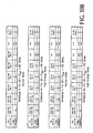
- the initial sensing pulse and the series of steps between the end of the positive phase and the beginning of negative phase have been omitted from Figs. 6-9, and it is assumed the variable resistor discussed above is not used.
- Figs. 6-9 are all examples of the "high-energy" mode. Fig.
- Fig. 6 which corresponds to Schedule 3A in Fig. 10A, is based on a patient impedance of 50 ohms, in which case the microprocessor selects an initial series-connected resistance of 30 ohms and a residual series-connected resistance of 0 ohms at the end of the positive phase.
- the total energy delivered to the patient is about 182 joules.
- Fig. 7, corresponding to Schedule 4A is based on a patient impedance of 75 ohms, an initial resistance of 10 ohms, a residual resistance of 0 ohms, and an energy of 222 joules.
- Fig. 7 corresponding to Schedule 4A
- corresponding to Schedule 5A is based on a patient impedance of 100 ohms, an initial resistance of 0 ohms, and a residual resistance of 0 ohms, and an energy of 217 joules.
- Fig. 9, corresponding to Schedule 5A is based on a patient impedance of 125 ohms, an initial resistance of 40 ohms, a residual resistance of 0 ohms, and an energy of 199 joules.
- Fig. 11 includes a table, corresponding to the "normal" mode of operation, that identifies, as a function of the patient impedance, the positive-phase current (in amps), ripple (in amps, assuming the variable resistor is not used), tilt of the negative phase (expressed as a percentage of the initial current value of the negative phase), total delivered energy (in joules), and the deviation of the total delivered energy from the normal mode's "rating" of 150 joules.
- Fig. 11 includes a table, corresponding to the "normal" mode of operation, that identifies, as a function of the patient impedance, the positive-phase current (in amps), ripple (in amps, assuming the variable resistor is not used), tilt of the negative phase (expressed as a percentage of the initial current value of the negative phase), total delivered energy (in joules), and the deviation of the total delivered energy from the normal mode's "rating" of 150 joules.
- 11 also includes a similar table for the "high-energy" mode of operation, identifying positive-phase current, tilt of the positive phase (based on a straight-line average through the ripples), ripple, tilt of the negative phase, total delivered energy, and the deviation of the total delivered energy from the "rating" of 170 joules.
- the storage capacitor In both the high-energy and normal modes described above, the storage capacitor is charged to its maximum voltage of 2200 volts. Other modes of operation can be developed in which the storage capacitor is charged to a lesser voltage, or in which different resistance schedules are used.
Applications Claiming Priority (15)
| Application Number | Priority Date | Filing Date | Title |
|---|---|---|---|
| US769045 | 1991-09-30 | ||
| US08/769,777 US5800463A (en) | 1996-12-18 | 1996-12-18 | Electrotherapy circuit having controlled peak current |
| US769776 | 1996-12-18 | ||
| US08/769,778 US5769872A (en) | 1996-12-18 | 1996-12-18 | Electrotherapy circuit and method for shaping current waveforms |
| US769046 | 1996-12-18 | ||
| US08/769,046 US5797968A (en) | 1996-12-18 | 1996-12-18 | Electrotherapy circuit for producing current waveform with sawtooth ripple |
| US769777 | 1996-12-18 | ||
| US08/769,045 US5800462A (en) | 1996-12-18 | 1996-12-18 | Electrotherapy circuit for producing therapeutic discharge waveform based on high-current sensing pulse |
| US08/769,773 US6096063A (en) | 1996-12-18 | 1996-12-18 | Electrotherapy circuit having controlled current discharge based on patient-dependent electrical parameter |
| US08/769,776 US5733310A (en) | 1996-12-18 | 1996-12-18 | Electrotherapy circuit and method for producing therapeutic discharge waveform immediately following sensing pulse |
| US769773 | 1996-12-18 | ||
| US08/910,757 US5904706A (en) | 1996-12-18 | 1997-08-13 | Method and apparatus for producing electrotherapy current waveform with ripple |
| US910757 | 1997-08-13 | ||
| EP97954585A EP0973582B1 (de) | 1996-12-18 | 1997-12-16 | Stromwellenform für elektrotherapy |
| US769778 | 2010-04-29 |
Related Parent Applications (1)
| Application Number | Title | Priority Date | Filing Date |
|---|---|---|---|
| EP97954585A Division EP0973582B1 (de) | 1996-12-18 | 1997-12-16 | Stromwellenform für elektrotherapy |
Publications (1)
| Publication Number | Publication Date |
|---|---|
| EP1535645A1 true EP1535645A1 (de) | 2005-06-01 |
Family
ID=27569916
Family Applications (2)
| Application Number | Title | Priority Date | Filing Date |
|---|---|---|---|
| EP97954585A Expired - Lifetime EP0973582B1 (de) | 1996-12-18 | 1997-12-16 | Stromwellenform für elektrotherapy |
| EP05075510A Withdrawn EP1535645A1 (de) | 1996-12-18 | 1997-12-16 | Sromwellenform für Elektrotherapie |
Family Applications Before (1)
| Application Number | Title | Priority Date | Filing Date |
|---|---|---|---|
| EP97954585A Expired - Lifetime EP0973582B1 (de) | 1996-12-18 | 1997-12-16 | Stromwellenform für elektrotherapy |
Country Status (4)
| Country | Link |
|---|---|
| EP (2) | EP0973582B1 (de) |
| JP (1) | JP4108758B2 (de) |
| DE (1) | DE69733276T2 (de) |
| WO (1) | WO1998026841A1 (de) |
Cited By (4)
| Publication number | Priority date | Publication date | Assignee | Title |
|---|---|---|---|---|
| WO2009078942A3 (en) * | 2007-12-13 | 2009-08-13 | Cardiac Pacemakers Inc | Defibrillation shock output circuit |
| US8433404B2 (en) | 2009-05-19 | 2013-04-30 | Cardiac Pacemakers, Inc. | Integrated high voltage output circuit |
| US9415230B2 (en) | 2006-02-01 | 2016-08-16 | Koninklijke Philips N.V. | Energy efficient defibrillation current limiter |
| WO2021242882A1 (en) * | 2020-05-26 | 2021-12-02 | Zoll Medical Corporation | Electrotherapeutic waveform and pulse generation and delivery system and method |
Families Citing this family (16)
| Publication number | Priority date | Publication date | Assignee | Title |
|---|---|---|---|---|
| FR2788699B1 (fr) | 1999-01-27 | 2001-05-25 | Bruker Medical Sa | Impulsions ou serie d'impulsions de defibrillation et dispositif pour les generer |
| FR2879937B1 (fr) * | 2004-12-23 | 2008-01-11 | Schiller Medical Sas | Defibrillateur dont le circuit de decharge est securise et comporte un pont en h |
| JP5563652B2 (ja) | 2009-03-17 | 2014-07-30 | カーディオスライヴ インコーポレイテッド | 体外除細動器 |
| WO2010146492A1 (en) | 2009-06-19 | 2010-12-23 | Koninklijke Philips Electronics, N.V. | Biphasic defibrillator waveform with adjustable second phase tilt |
| EP2446927A1 (de) * | 2010-10-28 | 2012-05-02 | Schiller Medical S.A.S. | Ultrakurze elektrische Hochspannungsdefibrillationsimpulse |
| US10149973B2 (en) | 2013-06-14 | 2018-12-11 | Cardiothrive, Inc. | Multipart non-uniform patient contact interface and method of use |
| US10279189B2 (en) | 2013-06-14 | 2019-05-07 | Cardiothrive, Inc. | Wearable multiphasic cardioverter defibrillator system and method |
| US9616243B2 (en) | 2013-06-14 | 2017-04-11 | Cardiothrive, Inc. | Dynamically adjustable multiphasic defibrillator pulse system and method |
| US9833630B2 (en) | 2013-06-14 | 2017-12-05 | Cardiothrive, Inc. | Biphasic or multiphasic pulse waveform and method |
| EP4039322B1 (de) | 2014-02-24 | 2023-09-06 | Element Science, Inc. | Externer defibrillator |
| CA2994436A1 (en) | 2015-08-26 | 2017-03-02 | Element Science, Inc. | Wearable devices |
| KR102187563B1 (ko) * | 2018-01-19 | 2020-12-07 | 주식회사 아모센스 | 피부 미용 기기의 출력 제어 장치 및 방법 |
| CN111565794A (zh) * | 2018-01-19 | 2020-08-21 | 阿莫善斯有限公司 | 用于控制皮肤护理美容仪器的输出的设备和方法 |
| KR102187629B1 (ko) * | 2018-01-19 | 2020-12-07 | 주식회사 아모센스 | 피부 미용 기기의 출력 제어 장치 |
| JP2022504629A (ja) | 2018-10-10 | 2022-01-13 | エレメント サイエンス,インク | 使い捨て部品と再使用可能部品を備えたウェアラブル医療機器 |
| US11638819B2 (en) | 2020-09-11 | 2023-05-02 | Galvanize Therapeutics, Inc. | Signal generators for use with tissue modification systems |
Citations (16)
| Publication number | Priority date | Publication date | Assignee | Title |
|---|---|---|---|---|
| US3258013A (en) * | 1963-07-01 | 1966-06-28 | Zenith Radio Corp | Defibrillators |
| US3886950A (en) * | 1973-10-01 | 1975-06-03 | Spacelabs Inc | Defibrillator |
| US4823796A (en) * | 1987-04-03 | 1989-04-25 | Laerdal Manufacturing Corp. | Defibrillator circuit for producing a trapezoidal defibrillation pulse |
| EP0326290A1 (de) * | 1988-01-19 | 1989-08-02 | Telectronics N.V. | Verfahren und Apparat zur Anwendung von asymmetrischen, zweiphasigen, abgeschnittenen exponentiellen Gegenschocks |
| EP0445800A1 (de) * | 1990-03-07 | 1991-09-11 | Müller, Gerhard | Elektrische Schaltung zum Bereitstellen eines Hochspannungsimpulses, inbesondere für einen Defibrillator |
| US5199429A (en) | 1991-05-23 | 1993-04-06 | Angemed, Inc. | Implantable defibrillator system employing capacitor switching networks |
| EP0546666A2 (de) * | 1991-11-08 | 1993-06-16 | Physio-Control Corporation | Elektronische Schaltung zur Energieübertragung |
| US5230336A (en) | 1991-08-16 | 1993-07-27 | Ventritex, Inc. | Method and apparatus for impedance based automatic pulse duration adjustment for defibrillation shock delivery |
| EP0553864A2 (de) * | 1992-01-30 | 1993-08-04 | Cardiac Pacemakers, Inc. | Defibrillator-Wellenformerzeuger zum Erzeugen von Langzeitwellenformen |
| EP0558353A2 (de) * | 1992-02-26 | 1993-09-01 | Angemed, Inc. | Optimale Energiesteuerung für einen implantierbaren Defibrillator |
| US5350403A (en) | 1992-06-17 | 1994-09-27 | Siemens Aktiengesellschaft | Apparatus for charging living tissue with electrical pulses |
| US5391186A (en) * | 1993-12-13 | 1995-02-21 | Angeion Corporation | Method and apparatus for utilizing short tau capacitors in an implantable cardioverter defibrillator |
| WO1995005215A2 (en) | 1993-08-06 | 1995-02-23 | Heartstream, Inc. | Electrotherapy method and apparatus |
| US5431687A (en) * | 1993-04-09 | 1995-07-11 | Angeion Corporation | Impedance timed defibrillation system |
| US5531764A (en) * | 1992-03-24 | 1996-07-02 | Angeion Corporation | Implantable defibrillator system and method having successive changeable defibrillation waveforms |
| WO1997038753A1 (en) * | 1996-04-12 | 1997-10-23 | Survivalink Corporation | External defibrillation waveforms |
Family Cites Families (2)
| Publication number | Priority date | Publication date | Assignee | Title |
|---|---|---|---|---|
| US5507781A (en) * | 1991-05-23 | 1996-04-16 | Angeion Corporation | Implantable defibrillator system with capacitor switching circuitry |
| DE59209886D1 (de) * | 1992-05-12 | 2001-02-15 | Pacesetter Ab Jaerfaella | Implantierbares Defibrillationssystem |
-
1997
- 1997-12-16 DE DE69733276T patent/DE69733276T2/de not_active Expired - Lifetime
- 1997-12-16 JP JP52797698A patent/JP4108758B2/ja not_active Expired - Fee Related
- 1997-12-16 EP EP97954585A patent/EP0973582B1/de not_active Expired - Lifetime
- 1997-12-16 WO PCT/US1997/023400 patent/WO1998026841A1/en active IP Right Grant
- 1997-12-16 EP EP05075510A patent/EP1535645A1/de not_active Withdrawn
Patent Citations (17)
| Publication number | Priority date | Publication date | Assignee | Title |
|---|---|---|---|---|
| US3258013A (en) * | 1963-07-01 | 1966-06-28 | Zenith Radio Corp | Defibrillators |
| US3886950A (en) * | 1973-10-01 | 1975-06-03 | Spacelabs Inc | Defibrillator |
| US4823796A (en) * | 1987-04-03 | 1989-04-25 | Laerdal Manufacturing Corp. | Defibrillator circuit for producing a trapezoidal defibrillation pulse |
| EP0326290A1 (de) * | 1988-01-19 | 1989-08-02 | Telectronics N.V. | Verfahren und Apparat zur Anwendung von asymmetrischen, zweiphasigen, abgeschnittenen exponentiellen Gegenschocks |
| EP0445800A1 (de) * | 1990-03-07 | 1991-09-11 | Müller, Gerhard | Elektrische Schaltung zum Bereitstellen eines Hochspannungsimpulses, inbesondere für einen Defibrillator |
| US5199429A (en) | 1991-05-23 | 1993-04-06 | Angemed, Inc. | Implantable defibrillator system employing capacitor switching networks |
| US5230336A (en) | 1991-08-16 | 1993-07-27 | Ventritex, Inc. | Method and apparatus for impedance based automatic pulse duration adjustment for defibrillation shock delivery |
| EP0546666A2 (de) * | 1991-11-08 | 1993-06-16 | Physio-Control Corporation | Elektronische Schaltung zur Energieübertragung |
| EP0553864A2 (de) * | 1992-01-30 | 1993-08-04 | Cardiac Pacemakers, Inc. | Defibrillator-Wellenformerzeuger zum Erzeugen von Langzeitwellenformen |
| EP0558353A2 (de) * | 1992-02-26 | 1993-09-01 | Angemed, Inc. | Optimale Energiesteuerung für einen implantierbaren Defibrillator |
| US5514160A (en) | 1992-02-26 | 1996-05-07 | Angeion Corporation | Implantable defibrillator for producing a rectangular-shaped defibrillation waveform |
| US5531764A (en) * | 1992-03-24 | 1996-07-02 | Angeion Corporation | Implantable defibrillator system and method having successive changeable defibrillation waveforms |
| US5350403A (en) | 1992-06-17 | 1994-09-27 | Siemens Aktiengesellschaft | Apparatus for charging living tissue with electrical pulses |
| US5431687A (en) * | 1993-04-09 | 1995-07-11 | Angeion Corporation | Impedance timed defibrillation system |
| WO1995005215A2 (en) | 1993-08-06 | 1995-02-23 | Heartstream, Inc. | Electrotherapy method and apparatus |
| US5391186A (en) * | 1993-12-13 | 1995-02-21 | Angeion Corporation | Method and apparatus for utilizing short tau capacitors in an implantable cardioverter defibrillator |
| WO1997038753A1 (en) * | 1996-04-12 | 1997-10-23 | Survivalink Corporation | External defibrillation waveforms |
Non-Patent Citations (1)
| Title |
|---|
| ALFERNESS C ET AL: "THE INFLUENCE OF SHOCK WAVEFORMS ON DEFIBRILLATION EFFICACY", IEEE ENGINEERING IN MEDICINE AND BIOLOGY MAGAZINE, IEEE SERVICE CENTER, PISACATAWAY, NJ, US, vol. 9, no. 2, 1 June 1990 (1990-06-01), pages 25 - 27, XP000173566, ISSN: 0739-5175, DOI: 10.1109/51.57863 * |
Cited By (6)
| Publication number | Priority date | Publication date | Assignee | Title |
|---|---|---|---|---|
| US9415230B2 (en) | 2006-02-01 | 2016-08-16 | Koninklijke Philips N.V. | Energy efficient defibrillation current limiter |
| WO2009078942A3 (en) * | 2007-12-13 | 2009-08-13 | Cardiac Pacemakers Inc | Defibrillation shock output circuit |
| US8116865B2 (en) | 2007-12-13 | 2012-02-14 | Cardiac Pacemarkers, Inc. | Defibrillation shock output circuit |
| US8489187B2 (en) | 2007-12-13 | 2013-07-16 | Cardiac Pacemakers, Inc. | Defibrillation shock output circuit |
| US8433404B2 (en) | 2009-05-19 | 2013-04-30 | Cardiac Pacemakers, Inc. | Integrated high voltage output circuit |
| WO2021242882A1 (en) * | 2020-05-26 | 2021-12-02 | Zoll Medical Corporation | Electrotherapeutic waveform and pulse generation and delivery system and method |
Also Published As
| Publication number | Publication date |
|---|---|
| DE69733276D1 (de) | 2005-06-16 |
| EP0973582A4 (de) | 2001-02-07 |
| EP0973582B1 (de) | 2005-05-11 |
| EP0973582A1 (de) | 2000-01-26 |
| DE69733276T2 (de) | 2006-05-04 |
| JP2001506157A (ja) | 2001-05-15 |
| WO1998026841A1 (en) | 1998-06-25 |
| JP4108758B2 (ja) | 2008-06-25 |
Similar Documents
| Publication | Publication Date | Title |
|---|---|---|
| US5733310A (en) | Electrotherapy circuit and method for producing therapeutic discharge waveform immediately following sensing pulse | |
| US6096063A (en) | Electrotherapy circuit having controlled current discharge based on patient-dependent electrical parameter | |
| US5769872A (en) | Electrotherapy circuit and method for shaping current waveforms | |
| EP0973582B1 (de) | Stromwellenform für elektrotherapy | |
| US5735879A (en) | Electrotherapy method for external defibrillators | |
| US5749904A (en) | Electrotherapy method utilizing patient dependent electrical parameters | |
| EP0808639B1 (de) | Von einem Patienten tragbare Energieabgabevorrichtung | |
| US6241751B1 (en) | Defibrillator with impedance-compensated energy delivery | |
| EP1118353B1 (de) | Auf Ladung basierte Vorrichtung zur Defibrillation | |
| US7079894B2 (en) | Damped biphasic energy delivery circuit for a defibrillator | |
| US5797968A (en) | Electrotherapy circuit for producing current waveform with sawtooth ripple | |
| US20080177342A1 (en) | Defibrillator With Impedance-Compensated Energy Delivery | |
| US5904706A (en) | Method and apparatus for producing electrotherapy current waveform with ripple | |
| US5800462A (en) | Electrotherapy circuit for producing therapeutic discharge waveform based on high-current sensing pulse | |
| US5800463A (en) | Electrotherapy circuit having controlled peak current | |
| EP0956095B1 (de) | High energy defibrillator employing current control circuitry | |
| US20100228305A1 (en) | Energy Efficient Defibrillation Current Limiter | |
| EP1458445B1 (de) | Vorrichtung zur abgabe von defibrillations- und reizungsenergie aus einer einzigen energiequelle | |
| EP0888149B1 (de) | Elektrotherapiegerät |
Legal Events
| Date | Code | Title | Description |
|---|---|---|---|
| PUAI | Public reference made under article 153(3) epc to a published international application that has entered the european phase |
Free format text: ORIGINAL CODE: 0009012 |
|
| 17P | Request for examination filed |
Effective date: 20050302 |
|
| AC | Divisional application: reference to earlier application |
Ref document number: 0973582 Country of ref document: EP Kind code of ref document: P |
|
| AK | Designated contracting states |
Kind code of ref document: A1 Designated state(s): DE FR GB |
|
| RIN1 | Information on inventor provided before grant (corrected) |
Inventor name: AYATI, SHERVIN Inventor name: LOPIN, MICHAEL L. |
|
| AKX | Designation fees paid |
Designated state(s): DE FR GB |
|
| RAP1 | Party data changed (applicant data changed or rights of an application transferred) |
Owner name: ZOLL MEDICAL CORPORATION |
|
| 17Q | First examination report despatched |
Effective date: 20100325 |
|
| STAA | Information on the status of an ep patent application or granted ep patent |
Free format text: STATUS: EXAMINATION IS IN PROGRESS |
|
| STAA | Information on the status of an ep patent application or granted ep patent |
Free format text: STATUS: THE APPLICATION IS DEEMED TO BE WITHDRAWN |
|
| 18D | Application deemed to be withdrawn |
Effective date: 20170701 |