EP1535640B1 - Sicherheitsspritze - Google Patents
Sicherheitsspritze Download PDFInfo
- Publication number
- EP1535640B1 EP1535640B1 EP03257489A EP03257489A EP1535640B1 EP 1535640 B1 EP1535640 B1 EP 1535640B1 EP 03257489 A EP03257489 A EP 03257489A EP 03257489 A EP03257489 A EP 03257489A EP 1535640 B1 EP1535640 B1 EP 1535640B1
- Authority
- EP
- European Patent Office
- Prior art keywords
- needle
- slidable sleeve
- safety
- pack
- hub
- Prior art date
- Legal status (The legal status is an assumption and is not a legal conclusion. Google has not performed a legal analysis and makes no representation as to the accuracy of the status listed.)
- Expired - Lifetime
Links
- 238000002347 injection Methods 0.000 claims abstract description 38
- 239000007924 injection Substances 0.000 claims abstract description 38
- 230000007246 mechanism Effects 0.000 claims description 19
- 239000000463 material Substances 0.000 claims description 14
- 238000000034 method Methods 0.000 claims description 7
- 239000012528 membrane Substances 0.000 claims description 6
- 239000004033 plastic Substances 0.000 claims description 5
- 229920003023 plastic Polymers 0.000 claims description 5
- IAYPIBMASNFSPL-UHFFFAOYSA-N Ethylene oxide Chemical compound C1CO1 IAYPIBMASNFSPL-UHFFFAOYSA-N 0.000 claims description 3
- 230000037452 priming Effects 0.000 claims description 3
- 208000012266 Needlestick injury Diseases 0.000 abstract description 10
- 239000003814 drug Substances 0.000 description 13
- 229940079593 drug Drugs 0.000 description 12
- 230000008901 benefit Effects 0.000 description 3
- 238000006073 displacement reaction Methods 0.000 description 3
- 239000011521 glass Substances 0.000 description 3
- 238000001990 intravenous administration Methods 0.000 description 3
- 230000001681 protective effect Effects 0.000 description 3
- 210000003491 skin Anatomy 0.000 description 3
- 238000004659 sterilization and disinfection Methods 0.000 description 3
- 238000001647 drug administration Methods 0.000 description 2
- 210000002615 epidermis Anatomy 0.000 description 2
- 229920001903 high density polyethylene Polymers 0.000 description 2
- 239000004700 high-density polyethylene Substances 0.000 description 2
- 239000000314 lubricant Substances 0.000 description 2
- 239000002184 metal Substances 0.000 description 2
- 229920000642 polymer Polymers 0.000 description 2
- 229940071643 prefilled syringe Drugs 0.000 description 2
- 230000008569 process Effects 0.000 description 2
- 210000003462 vein Anatomy 0.000 description 2
- 241000894006 Bacteria Species 0.000 description 1
- 206010028980 Neoplasm Diseases 0.000 description 1
- 239000004793 Polystyrene Substances 0.000 description 1
- 239000004775 Tyvek Substances 0.000 description 1
- 229920000690 Tyvek Polymers 0.000 description 1
- 208000027418 Wounds and injury Diseases 0.000 description 1
- 201000011510 cancer Diseases 0.000 description 1
- 238000006243 chemical reaction Methods 0.000 description 1
- 238000002512 chemotherapy Methods 0.000 description 1
- 230000001010 compromised effect Effects 0.000 description 1
- 238000011109 contamination Methods 0.000 description 1
- 229940127089 cytotoxic agent Drugs 0.000 description 1
- 239000002254 cytotoxic agent Substances 0.000 description 1
- 231100000599 cytotoxic agent Toxicity 0.000 description 1
- 230000006378 damage Effects 0.000 description 1
- 230000000994 depressogenic effect Effects 0.000 description 1
- 239000003085 diluting agent Substances 0.000 description 1
- 239000013013 elastic material Substances 0.000 description 1
- 230000008020 evaporation Effects 0.000 description 1
- 238000001704 evaporation Methods 0.000 description 1
- 230000036541 health Effects 0.000 description 1
- 208000006454 hepatitis Diseases 0.000 description 1
- 231100000283 hepatitis Toxicity 0.000 description 1
- 208000015181 infectious disease Diseases 0.000 description 1
- 208000014674 injury Diseases 0.000 description 1
- 238000003780 insertion Methods 0.000 description 1
- 230000037431 insertion Effects 0.000 description 1
- 238000012986 modification Methods 0.000 description 1
- 230000004048 modification Effects 0.000 description 1
- 206010033675 panniculitis Diseases 0.000 description 1
- 239000000546 pharmaceutical excipient Substances 0.000 description 1
- 238000009512 pharmaceutical packaging Methods 0.000 description 1
- 239000004417 polycarbonate Substances 0.000 description 1
- 229920000515 polycarbonate Polymers 0.000 description 1
- 229920000728 polyester Polymers 0.000 description 1
- 229920012287 polyphenylene sulfone Polymers 0.000 description 1
- 229920002223 polystyrene Polymers 0.000 description 1
- 229920000915 polyvinyl chloride Polymers 0.000 description 1
- 239000011148 porous material Substances 0.000 description 1
- 230000036316 preload Effects 0.000 description 1
- 230000002028 premature Effects 0.000 description 1
- 230000005855 radiation Effects 0.000 description 1
- 230000000717 retained effect Effects 0.000 description 1
- 238000005096 rolling process Methods 0.000 description 1
- 238000007789 sealing Methods 0.000 description 1
- 230000007480 spreading Effects 0.000 description 1
- 229910001220 stainless steel Inorganic materials 0.000 description 1
- 239000010935 stainless steel Substances 0.000 description 1
- 230000001954 sterilising effect Effects 0.000 description 1
- 210000000434 stratum corneum Anatomy 0.000 description 1
- 210000004304 subcutaneous tissue Anatomy 0.000 description 1
- 210000001519 tissue Anatomy 0.000 description 1
Images


Classifications
-
- A—HUMAN NECESSITIES
- A61—MEDICAL OR VETERINARY SCIENCE; HYGIENE
- A61M—DEVICES FOR INTRODUCING MEDIA INTO, OR ONTO, THE BODY; DEVICES FOR TRANSDUCING BODY MEDIA OR FOR TAKING MEDIA FROM THE BODY; DEVICES FOR PRODUCING OR ENDING SLEEP OR STUPOR
- A61M5/00—Devices for bringing media into the body in a subcutaneous, intra-vascular or intramuscular way; Accessories therefor, e.g. filling or cleaning devices, arm-rests
- A61M5/46—Devices for bringing media into the body in a subcutaneous, intra-vascular or intramuscular way; Accessories therefor, e.g. filling or cleaning devices, arm-rests having means for controlling depth of insertion
-
- A—HUMAN NECESSITIES
- A61—MEDICAL OR VETERINARY SCIENCE; HYGIENE
- A61M—DEVICES FOR INTRODUCING MEDIA INTO, OR ONTO, THE BODY; DEVICES FOR TRANSDUCING BODY MEDIA OR FOR TAKING MEDIA FROM THE BODY; DEVICES FOR PRODUCING OR ENDING SLEEP OR STUPOR
- A61M5/00—Devices for bringing media into the body in a subcutaneous, intra-vascular or intramuscular way; Accessories therefor, e.g. filling or cleaning devices, arm-rests
- A61M5/002—Packages specially adapted therefor, e.g. for syringes or needles, kits for diabetics
-
- A—HUMAN NECESSITIES
- A61—MEDICAL OR VETERINARY SCIENCE; HYGIENE
- A61M—DEVICES FOR INTRODUCING MEDIA INTO, OR ONTO, THE BODY; DEVICES FOR TRANSDUCING BODY MEDIA OR FOR TAKING MEDIA FROM THE BODY; DEVICES FOR PRODUCING OR ENDING SLEEP OR STUPOR
- A61M5/00—Devices for bringing media into the body in a subcutaneous, intra-vascular or intramuscular way; Accessories therefor, e.g. filling or cleaning devices, arm-rests
- A61M5/178—Syringes
- A61M5/31—Details
- A61M5/32—Needles; Details of needles pertaining to their connection with syringe or hub; Accessories for bringing the needle into, or holding the needle on, the body; Devices for protection of needles
- A61M5/3205—Apparatus for removing or disposing of used needles or syringes, e.g. containers; Means for protection against accidental injuries from used needles
- A61M5/321—Means for protection against accidental injuries by used needles
- A61M5/3243—Means for protection against accidental injuries by used needles being axially-extensible, e.g. protective sleeves coaxially slidable on the syringe barrel
- A61M5/326—Fully automatic sleeve extension, i.e. in which triggering of the sleeve does not require a deliberate action by the user
-
- A—HUMAN NECESSITIES
- A61—MEDICAL OR VETERINARY SCIENCE; HYGIENE
- A61M—DEVICES FOR INTRODUCING MEDIA INTO, OR ONTO, THE BODY; DEVICES FOR TRANSDUCING BODY MEDIA OR FOR TAKING MEDIA FROM THE BODY; DEVICES FOR PRODUCING OR ENDING SLEEP OR STUPOR
- A61M5/00—Devices for bringing media into the body in a subcutaneous, intra-vascular or intramuscular way; Accessories therefor, e.g. filling or cleaning devices, arm-rests
- A61M5/178—Syringes
- A61M5/31—Details
- A61M5/32—Needles; Details of needles pertaining to their connection with syringe or hub; Accessories for bringing the needle into, or holding the needle on, the body; Devices for protection of needles
- A61M5/3205—Apparatus for removing or disposing of used needles or syringes, e.g. containers; Means for protection against accidental injuries from used needles
- A61M5/321—Means for protection against accidental injuries by used needles
- A61M5/3243—Means for protection against accidental injuries by used needles being axially-extensible, e.g. protective sleeves coaxially slidable on the syringe barrel
- A61M5/3245—Constructional features thereof, e.g. to improve manipulation or functioning
- A61M2005/3247—Means to impede repositioning of protection sleeve from needle covering to needle uncovering position
-
- A—HUMAN NECESSITIES
- A61—MEDICAL OR VETERINARY SCIENCE; HYGIENE
- A61M—DEVICES FOR INTRODUCING MEDIA INTO, OR ONTO, THE BODY; DEVICES FOR TRANSDUCING BODY MEDIA OR FOR TAKING MEDIA FROM THE BODY; DEVICES FOR PRODUCING OR ENDING SLEEP OR STUPOR
- A61M5/00—Devices for bringing media into the body in a subcutaneous, intra-vascular or intramuscular way; Accessories therefor, e.g. filling or cleaning devices, arm-rests
- A61M5/178—Syringes
- A61M5/31—Details
- A61M5/32—Needles; Details of needles pertaining to their connection with syringe or hub; Accessories for bringing the needle into, or holding the needle on, the body; Devices for protection of needles
- A61M5/3205—Apparatus for removing or disposing of used needles or syringes, e.g. containers; Means for protection against accidental injuries from used needles
- A61M5/321—Means for protection against accidental injuries by used needles
- A61M5/3243—Means for protection against accidental injuries by used needles being axially-extensible, e.g. protective sleeves coaxially slidable on the syringe barrel
- A61M5/326—Fully automatic sleeve extension, i.e. in which triggering of the sleeve does not require a deliberate action by the user
- A61M2005/3267—Biased sleeves where the needle is uncovered by insertion of the needle into a patient's body
- A61M2005/3268—Biased sleeves where the needle is uncovered by insertion of the needle into a patient's body having cantilever elastically spreadable arms, e.g. to accumulate energy during needle uncovering movement for urging protection sleeve to return to needle covering position
-
- A—HUMAN NECESSITIES
- A61—MEDICAL OR VETERINARY SCIENCE; HYGIENE
- A61M—DEVICES FOR INTRODUCING MEDIA INTO, OR ONTO, THE BODY; DEVICES FOR TRANSDUCING BODY MEDIA OR FOR TAKING MEDIA FROM THE BODY; DEVICES FOR PRODUCING OR ENDING SLEEP OR STUPOR
- A61M5/00—Devices for bringing media into the body in a subcutaneous, intra-vascular or intramuscular way; Accessories therefor, e.g. filling or cleaning devices, arm-rests
- A61M5/178—Syringes
- A61M5/31—Details
- A61M5/32—Needles; Details of needles pertaining to their connection with syringe or hub; Accessories for bringing the needle into, or holding the needle on, the body; Devices for protection of needles
- A61M5/3205—Apparatus for removing or disposing of used needles or syringes, e.g. containers; Means for protection against accidental injuries from used needles
- A61M5/321—Means for protection against accidental injuries by used needles
- A61M5/3243—Means for protection against accidental injuries by used needles being axially-extensible, e.g. protective sleeves coaxially slidable on the syringe barrel
- A61M5/3271—Means for protection against accidental injuries by used needles being axially-extensible, e.g. protective sleeves coaxially slidable on the syringe barrel with guiding tracks for controlled sliding of needle protective sleeve from needle exposing to needle covering position
- A61M5/3272—Means for protection against accidental injuries by used needles being axially-extensible, e.g. protective sleeves coaxially slidable on the syringe barrel with guiding tracks for controlled sliding of needle protective sleeve from needle exposing to needle covering position having projections following labyrinth paths
-
- A—HUMAN NECESSITIES
- A61—MEDICAL OR VETERINARY SCIENCE; HYGIENE
- A61M—DEVICES FOR INTRODUCING MEDIA INTO, OR ONTO, THE BODY; DEVICES FOR TRANSDUCING BODY MEDIA OR FOR TAKING MEDIA FROM THE BODY; DEVICES FOR PRODUCING OR ENDING SLEEP OR STUPOR
- A61M5/00—Devices for bringing media into the body in a subcutaneous, intra-vascular or intramuscular way; Accessories therefor, e.g. filling or cleaning devices, arm-rests
- A61M5/50—Devices for bringing media into the body in a subcutaneous, intra-vascular or intramuscular way; Accessories therefor, e.g. filling or cleaning devices, arm-rests having means for preventing re-use, or for indicating if defective, used, tampered with or unsterile
- A61M5/5086—Devices for bringing media into the body in a subcutaneous, intra-vascular or intramuscular way; Accessories therefor, e.g. filling or cleaning devices, arm-rests having means for preventing re-use, or for indicating if defective, used, tampered with or unsterile for indicating if defective, used, tampered with or unsterile
Definitions
- This invention relates to a safety needle and in particular to safety needle pack.
- Needle stick injuries carry a significant risk of spreading infection, such as HIV and hepatitis, and are commonplace among healthcare workers.
- the USA has led the way in introducing legislation that obliges healthcare providers to use the safest devices when giving injections, intravenous drug administration and similar invasive procedures.
- Other countries are following and, even without legislation, the ever-present risk of litigation has alerted pharmaceutical companies and health authorities to seek suitable safe devices.
- WO03/066141 discloses a safety shield system for a needle cannula of a pen needle injector or similar device, wherein a safety shield may be retracted from a first position enclosing the needle cannula to a second position exposing the needle cannula for injection.
- the safety shield system permits retraction of the safety shield during use, but extends the shield enclosing the needle cannula in a locked position following use. The end of the needle cannula is never exposed.
- a common requirement for drug administration is to draw the drug from a vial or bulk container, or first reconstitute a lyophilised drug, and then draw up the required volume of drug from the reconstitution vessel.
- Good practice demands that separate needles are used for such procedures, to avoid contamination and "coring" of the rubber vial closure, and from a practical viewpoint, the needle used to draw up the drug usually will be larger than the delivery needle.
- the present invention provides a safety needle comprising a hollow needle having a tip, a needle hub surrounding the hollow needle, a slidable sleeve slidably mounted on the needle hub and a pack surrounding the hollow needle, needle hub and slidable sleeve, the needle hub, the slidable sleeve and the pack each having a receiving end which is distal to the tip of the needle and an injection end which is proximal to the tip of the needle, wherein the receiving end of the needle hub is suitable for connection to an injection device and the slidable sleeve is adapted to slide in the direction of the length of the needle between an extended position in which the tip of the needle is located inside the slidable sleeve and a retracted position in which the tip of the needle projects from the slidable sleeve, via an intermediate position between the extended position and the retracted position in which the tip of the needle projects partially from the slidable sleeve, such that, in
- This safety needle pack protects the user from needle stick injuries while the safety accessory, namely the needle hub and the slidable sleeve, arc primed for use.
- the slidable sleeve is caused to move in to an intermediate position between the extended and retracted positions such that the needle bevel is exposed.
- the present invention also provides a method for priming an injection device comprising the steps of inserting an injection device in to the receiving end of the needle hub of the safety needle as claimed in any preceding claim, moving the pack towards the injection device such that the slidable sleeve moves in to the intermediate position, and removing the pack.
- the present invention further provides a method for injecting a patient using the safety needle as defined above.
- the applicants have found that the process of exposing the tip of the needle can, in itself lead to needle stick injuries. This is particularly undesirable where the user is injecting cytotoxic agents, for example during cancer chemotherapy.
- the safety needle pack of the present invention avoids such injuries by providing a pack which shields the user from the needle tip whilst the tip of the needle is being exposed, at least partially.
- the tip of the needle is not exposed to the extent that it is exposed when the user injects the needle through the skin of the patient but is exposed sufficiently for the user to see the bevel of the needle, in order to guide the tip in to a specific part of the patient or to aspirate air or expel any excess drug.
- the arrangement of the slidable sleeve and the needle hub hold the slidable sleeve in this intermediate position.
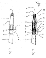
- Figs. 1-8 exemplify a safety needle for preventing needle stick injuries which is suitable for use with the pack of the present invention.
- Fig. 1 shows the general arrangement of a safety needle 1 (i.e. the safety needle accessory and the needle 3) of the type which may be used with the present invention as fitted to a male Luer taper connector 4 of syringe 2, with the end of the hollow (e.g. hypodermic) needle 3 enclosed by the slidable sleeve 5.
- the slidable sleeve 5 is prevented from longitudinal movement on the needle hub 7 by a locking ring 13, which may be removed by pulling on the tab 14.
- the removable locking ring may be connected to the needle hub and/or the slidable sleeve.
- the cylindrical shape of the needle hub and slidable sleeve may be replaced by triangular, rectangular or other shapes to suit the application.
- Fig. 2 is a cross-section through the axis of the safety needle 1.
- the needle hub 7 is cylindrical and terminates at the end which receives the syringe with a conical section 8, and is moulded onto the needle 3.
- the conical section 8 has an inner female Luer cone 24 which is shown frictionally attached to the male Luer cone 4 of syringe 2 (the Luer system for attaching the needle to the syringe has two main forms, that is a taper friction fit and a screw thread and both are included in the present invention).
- the cylindrical slidable sleeve 5 shrouds the needle 3 and the needle hub 7, and is freely sliding on and guided by the needle hub 7. At the receiving end (i.e.
- Locking ring 13 is moulded integrally with the slidable sleeve 5 by a frangible joint 15, and may be partially or wholly detached by pulling on the tab 14 to break the frangible joint 15. It is preferred that the ring 13 remains attached to the slidable sleeve 5 to reduce the number of discarded parts.
- the frangible joint provides a tamper-evident lock.
- the locking ring 13 may be moulded to the needle hub 7 via a suitable frangible connection.
- the slidable sleeve 5 When the locking ring 15 is removed, as shown in Fig. 3 the slidable sleeve 5 may be pushed in the direction of arrow X by acting on the face 6, when it will move relative to the needle hub 7 to expose the needle 3.
- the cantilever arms 9 As the slidable sleeve 5 moves, the cantilever arms 9 are forced outwards by the surface 18 of the conical section 8.
- the cantilever arms 9 are resilient and the reaction force against the surface 18 produce a resultant force Y acting against arrow X, so that when the original force is removed, the slidable sleeve 5 returns to cover the tip of needle 3. Since the restoring force is provided by the slidable sleeve 5 itself, no separate spring, e.g. a helical spring, is required in this embodiment although a separate spring could be used if desired
- the cantilever arms 9 may have pads 17 which bear onto the surface 18 and, by suitably designing the bearing surfaces of the pads 17, various spring characteristics may be obtained. Although four cantilever arms 9 are shown, any number could be employed. At least one cantilever arm 9 is required for this embodiment although 2 to 6 are preferred and particularly preferably four.
- the surface 18 is exemplified by a conical surface, other embodiments may be used within the scope of the present invention.
- the surface is straight, i.e. substantially conical by which the applicant means sufficiently conical to generate a restoring force, however, the surface need not be straight as shown, but may be curved to give a more linear return rate.
- the force Y could be substantially constant over a reasonable working stroke of the slidable sleeve 5.
- the whole surface 18 of the receiving end of the needle hub 17 need not be conical. In fact just one tapered section, e.g. a tapered ridge, would be sufficient. The tapered section does not have to project from the surface of the needle hub 7.
- the tapered section could also descend into the wall of the needle hub, i.e. a tapered detent rather than a tapered ridge. Also, as described below with reference to Fig. 8 , provided the slidable sleeve 5 is suitably configured, a projection in the surface 18 of the needle hub 7 will suffice.
- linearity of the return rate may be varied depending on the particular requirements for a particular application.
- the slidable sleeve preferably has a first extended position where the slidable sleeve is able to be moved towards the receiving end of the needle hub and a second extended position where the slidable sleeve is in a locked position.
- the different start and finish positions of the slidable sleeve 5 is achieved by a detent mechanism shown in Fig. 5 , which is to be read in conjunction with Figs. 2 , 3 and 4 .
- a detent integral with the slidable sleeve "switches” so that the return of the slidable sleeve trips a latching pawl, so that the slidable sleeve returns only to the "safe” position; that is the pawl prevents the slidable sleeve from being moved towards the syringe a second time, and thus protects the tip of the needle.
- an inside surface of the slidable sleeve has a pin 10 which engages a sprag 26 and a resilient pawl 19 attached to the needle hub 7 thereby holding the slidable sleeve in the first extended position and, in use, allowing the slidable sleeve to move into the second extended position.
- Pin 10 is integral or attached to the slidable sleeve 5.
- Sprag 26, resilient pawl 19, and recess 27 are moulded integrally with the needle hubs 7, 8, and the pin 10 extends into the recess, and allowed to move freely except where controlled by the detent and the boundaries of the recess.
- the slidable sleeve 5 is placed over the needle 3 with pin 10 proximate to the sprag 26 (formed as part of the needle hub 7) at position a ( Fig. 5 ).
- the pin 10 deflects the resilient pawl 19, until the pin 10 is trapped behind sprag 26 at position b .
- the slidable sleeve 5 is trapped on the needle hubs 7, 8 and cannot be removed without applying considerable force. This is the position of the components as supplied to the end user, and the location of the locking ring 13 takes account of this.
- the slidable sleeve 5 With the locking ring 13 removed, the slidable sleeve 5 is pushed further towards the syringe 2, and pin 10 again deflects the resilient pawl 19 until the pin 10 reaches position c .
- This distance i defines the initial displacement of the slidable sleeve 5, when starting the injection, and the tip of needle 3 may be level with the face 6 of slidable sleeve 5.
- the slidable sleeve 5 may now be moved towards the syringe until the pin 10 reaches the end wall 28 of the recess 27 at position d . This position defines the maximum displacement of slidable sleeve 5, and thus the maximum exposure of the needle 3.
- the detent mechanism is interchangeable between the slidable sleeve 5 and needle hub 7 if required.
- the detent mechanism described hereinabove is but one of a number of such mechanisms, the main requirement being to permit the following sequence of operation: permit the slidable sleeve to be moved sufficiently so that the opening in the slidable sleeve is level with or just in front of the needle tip, at which position the detent must be activated so that if the displacing force on the slidable sleeve is removed, the slidable sleeve slides forward and locks, thus protecting the user from contact with the needle tip.
- the tip of the needle would be about 3 mm back from the face of the opening in the slidable sleeve at the start, and 1 mm back from the face when the detent is activated.
- Fig. 7 shows the device 1 as previously described, except that in this embodiment the needle 3 is bonded into the outlet end of the syringe barrel 29.
- the needle is free to pass through the needle hub 7, and the cone 9 is adapted at 31 to snap-fit over the projection 30.
- the form of projection 30 is produced as a result of rolling the glass onto a mandrel, whereby the excess glass is forced in to the shape as shown.
- a more defined snap-fitting termination may be formed, the object being to make the device 1 difficult to remove after assembling it to the syringe barrel.
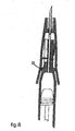
- Fig. 8 shows a safety needle 1 in which the needle hub 7 is integral with the barrel of the syringe 2.
- the slidable sleeve 5 is then attached to the needle hub 7 in the manner as described hereinbelow.
- the material of the needle hub 7, which also constitutes the barrel of the syringe, would, of course, have to be made from a drug-compatible material.
- Fig. 8 also shows the separate feature of the projection 32 on the surface 18 of the needle hub 7 which may be used to deflect the slidable sleeve 5 thereby generating the restoring force.
- This embodiment i.e. incorporating the projection 32, provides a highly non-linear return rate since the length of the slidable sleeve 5 is effectively reduced as the slidable sleeve 5 and the needle hub 7 are slid together, thereby increasing the stiffness of the slidable sleeve 5.
- the slidable sleeve has at least one cantilever arm which engages a helical track in the outer surface of the needle hub such that, in use, as the needle is inserted into a patient, the at least one cantilever arm is displaced radially by the helical track in the outer surface of the needle hub thereby generating the restoring force.
- the slidable sleeve 5 is caused to move towards the receiving end of the needle hub 7, one or more cantilever arms 9 are forced to follow the direction of the helical tracks. Since the cantilever arms 9 are resilient, a restoring force will be generated.
- the receiving end of the slidable sleeve itself may have elastic properties such that, in use, as the needle is inserted into a patient, the restoring force is generated within the slidable sleeve.
- elastic properties the applicant means that the restoring force is generated within a radially continuous slidable sleeve, i.e. a sleeve without cantilever arms.
- the elastic properties may be achieved by using an elastic material, such as an elastomeric polymer.
- the receiving end of the slidable sleeve may be concertinaed, with the ridges, of course, running parallel to the hollow needle.
- the elastic properties could also be generated using a circumambient spring attached to the slidable sleeve.
- the safety needle may incorporate an alternative, or additional, restoring mechanism, such as a helical spring.
- a helical spring Such safety needles are exemplified in US 4,911,693 , US 4,813,940 and US 5,104,384 .
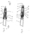
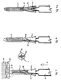
- Figs. 9-14a show an embodiment of the present invention in which the needle hub and the slidable sleeve are adapted to allow the slidable sleeve to be retracted into and held at an intermediate position between the extended position and the retracted position such that, in use, the tip of the needle 2 projects partially from the slidable sleeve, that is the needle bevel is exposed.
- the locking mechanism is not engaged and hence the slidable sleeve may be retracted further into the (fully) retracted position as it is inserted into the patient.
- exposing the tip of the needle partially allows the user to position the needle more precisely on, for example, the patient's skin, and also facilitates the aspiration of trapped air and excess drug.
- the use of the pack prevents needle stick injuries when the safety needle is in the intermediate position.
- Fig. 9 shows the device as assembled by the manufacturer, and comprises a needle hub 7, being of conical or other tapering form.
- Slidable sleeve 5 has cantilever arms 9 attached or integral, the arms terminating with a projection 33, which engages with undercut 34 of the needle hub 7, shown in greater detail in Fig. 9a .
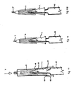
- this is a centre-line cross-section through the safety needle assembled into its pack 35.
- Pack 35 is releasably mounted on the needle hub and slidable sleeve.
- the pack 35 preferably tubular and also preferably made from a deep-drawn vacuum formed plastics material.
- the pack 35 is shown with a flange 36 and open at the receiving end of the needle hub 7, and closed at the injection end by the extension 37.
- the inner face of shoulder 38 rests on the end face of the slidable sleeve 5.
- the needle hub 7 has one or more projections 39, which provide a light frictional retaining force on the inside of the pack 35 to prevent the safety needle from falling out.
- the safety needle may be further retained inside the pack 35 by a releasable (peel-off) membrane 40, which is preferably gas permeable.
- the membrane 40 is bonded to flange 36, and may be made from a porous material such as Tyvek® which is spun-bonded high-density polyethylene available from DuPont and which is used extensively in pharmaceutical packaging to permit a sterilising gas, such as ethylene oxide, to penetrate the pack whilst preventing ingress of bacteria during storage. Other peelable materials may be used according to the sterilisation process used.
- the membrane 40 may have a tag 41 to assist removal.
- the needle hub 7 has a syringe adaptor 24 which may be configured to suit the common Luer taper or threaded Luer lock syringe nozzles.
- the user removes the peelable membrane 40 by pulling on tag 41. Holding the pack 35, the user pushes the adaptor 24 of the needle hub 7 in the direction of the arrow X onto the syringe connector 43. This causes the inner face of the shoulders 38 to press against face of slidable sleeve 5 which moves towards the syringe.
- the injection end of the pack 35 has an extended portion which is capable of housing the tip of the needle 3 in the intermediate position and the shoulders 38 of the extended portion abut against the injection end of the slidable sleeve thereby causing the slidable sleeve 5 to move in to the intermediate position when the pack 35 is caused to move towards the receiving end of the needle hub 7.
- the cantilever arms 9 are forced outwards as they travel up the surface of the needle hub 7, until the small shoulder 44 on the slidable sleeve 5 reaches the projection 45 on the needle hub 7, thus preventing further movement.
- at least one of the projections 33 snaps over a catch 46 on the needle hub 7.
- Fig. 12a shows the safety needle ready for use, as in Fig. 12 , but with an extension 47 on face of slidable sleeve 5 extended to shroud partly the tip of the needle 3, which will afford more protection, but make aspiration of air and excess drug slightly more difficult.
- the user pushes the needle 3 in the direction of arrow A through the patient's epidermis 48 and into the subcutaneous tissue 49, which brings the face of the slidable sleeve 5 into contact with the stratum corneum of the patient's epidermis 48. Further movement in the direction of arrow A pushes the slidable sleeve 5 towards the syringe 42, and thus the cantilever arms 9 are forced further outwards by the conical surface of the needle hub 7.
- the end of at least one cantilever arm 9 is forced against a cam 50 which causes the slidable sleeve 5 and cantilever arms 9 to rotate in the direction of arrow B, until the end of cantilever arm 9 drops into the groove 51.
- Groove 51 has a slope towards the needle, which maintains the resultant force of the cantilever arm 9.
- the resultant force of the cantilever arms 9 urges the slidable sleeve 5 towards the tip of the needle 3 until the tip of the needle 3 is shielded by the slidable sleeve 5.
- any slidable sleeve 5 may be locked into position using one or more projections 33 and corresponding one or more holes 52.
- Such an arrangement results in a less complex, and hence less costly, safety needle accessory and avoids introducing opposing frictional and/or detent forces which result from an integral but independent locking mechanism.
- An advantage of the projection 33/hole 52 mechanism is that the locking mechanism provides substantially no resistance against the restoring force as the slidable sleeve 5 moves from the retracted position to the extended position. When the slidable sleeve 5 reaches the extended position the locking mechanism engages which then resists the restoring force.
- the protective pack 35 confers safe storage and handling advantages, allows the safety needle to be assembled to a syringe without risking premature operation of the safety mechanism, and does not add to the overall cost of the device, since it is similar to the vacuum-formed packs already in use for needles and syringes. For the user, the operation of the safety needle is practically identical to the use of a standard needle.
- the coefficient of friction between the slidable sleeve 5 and the needle hub 7 is low, so that the resultant biasing force to return the slidable sleeve is not compromised by "stiction", or so high that the force required on the patient's skin to deflect the slidable sleeve 5 is excessive.
- the needle hub could be made from a high-density polyethylene or similar drug-compatible plastics material, and the slidable sleeve from an inexpensive plastics material such as polycarbonate, polystyrene, polyester or PVC.
- the slidable sleeve, or just the at least one cantilever arm may be made from metal, preferably stainless steel.
- the metal would be fabricated sufficiently thinly to provide the required elastic properties.
- a lubricant may be used, or a lubricant may be incorporated with the polymers.
- the materials should be suitable for sterilisation by gamma radiation, but it is possible to select materials compatible with sterilisation by steam or other gas such as ethylene oxide.
- the slidable sleeve prior to use, is not under any substantial load. Any substantial load indicates a load which is sufficient to cause the material of the slidable sleeve to undergo creepage during storage at ambient temperature.
- the syringe may be supplied empty or pre-filled.
- the syringe is preferably sealed using a sealing cap or plug to prevent evaporation or loss of the drug, excipient, carrier and/or diluent by, for example, thermal expansion.
- the same safety needle accessory described herein could form the basis of a intravenous giving set, so that the insertion of the needle into the patient's vein is simple and safe.
- the safety needle accessory of the present invention may be used with any suitable injection device.
Landscapes
- Health & Medical Sciences (AREA)
- Engineering & Computer Science (AREA)
- Hematology (AREA)
- Anesthesiology (AREA)
- Biomedical Technology (AREA)
- Heart & Thoracic Surgery (AREA)
- Vascular Medicine (AREA)
- Life Sciences & Earth Sciences (AREA)
- Animal Behavior & Ethology (AREA)
- General Health & Medical Sciences (AREA)
- Public Health (AREA)
- Veterinary Medicine (AREA)
- Diabetes (AREA)
- Environmental & Geological Engineering (AREA)
- Infusion, Injection, And Reservoir Apparatuses (AREA)
Claims (27)
- Sicherheitskantile (1), bestehend aus einer Hohlkanüle (3), die eine Spitze, einen die Hohlkanäle umschließenden Kanülenansatz (7), eine verschiebbar am Kanülenansatz montierte Gleithülse (5) sowie eine die Hohlkanüle, den Kanülenansatz und die Gleithülse umschließende Ummantelung (35) aufweist,
wobei der Kanülenansatz (7), die Gleithülse (5) und die Ummantelung (35) jeweils eine Eingangsseite aufweisen, die distal zur Spitze der Kanüle (3) angeordnet ist, und eine Injektionsseite, die proximal zur Spitze der Kanüle (3) angeordnet ist,
wobei die Eingangsseite des Kanülenansatzes (7) zum Verbinden mit einer Injektionsspritze geeignet ist und die Gleithülse (5) so ausgelegt ist, dass sie in Längsrichtung der Kanüle (3) zwischen einer ausgefahrenen Position, in der sich die Spitze der Kanüle (3) innerhalb der Gleithülse (5) befindet, und einer eingefahrenen Position, in der die Spitze der Kanüle (3) über die Gleithülse (5) hinausragt, über eine Mittelstellung zwischen der ausgefahrenen und der eingefahrenen Position, in der die Spitze der Kanüle (3) teilweise über die Gleithülse (5) hinausragt, gleiten kann, so dass bei der Anwendung die Gleithülse (5) zur Injektion in einen Patienten in die Mittelstellung bewegt wird und danach die Gleithülse (5) beim Einführen der Kanüle (3) in den Patienten in die eingefahrene Position bewegt wird,
wobei der Kanülenansatz (7) eine Außenfläche (18) aufweist, die so ausgelegt ist, dass die Gleithülse (5) abgelenkt wird, wenn die Kanüle (3) bei der Anwendung in den Patienten eingeführt wird, und die Gleithülse (5) elastisch an der Außenfläche (18) des Kanülenansatzes (7) abgestützt wird, so dass bei der Anwendung eine Rückholkraft innerhalb der Gleithülse (5) erzeugt wird, wenn die Bewegung der Gleithülse (5) in Richtung der Eingangsseite des Kanülenansatzes (7) und in die eingefahrene Position bewirkt wird, so dass bei Entfernen der Kanüle (3) vom Patienten die Rückholkraft bewirkt, dass die Gleithülse (5) sich in Richtung der Injektionsseite des Kanülenansatzes (7) und in die ausgefahrene Position bewegt; weiterhin weist die Sicherheitskanüle (1) einen Verriegelungsmechanismus auf, der in der Lage ist, die Gleithülse nach dem Entfernen der Kanüle vom Patienten in der ausgefahrenen Position zu halten, wobei die Ummantelung (35) lösbar auf dem Kanülenansatz (7) und der Gleithülse (5) angebracht ist, so dass die Injektionsseite der Ummantelung (35) mindestens die Injektionsseite der Kanüle (3) bedeckt, und die Eingangsseite der Ummantelung (35) einen offenen Teil aufweist, der die Eingangsseite des Kanülenansatzes (7) freilegt, und bei der somit ausgelösten Bewegung der Ummantelung (35) in Richtung der Eingangsseite des Kanülenansatzes (7) die Ummantelung (35) in die Gleithülse (5) eingreift, die aus der ausgefahrenen Position in die Mittelstellung eingefahren wird. - Sicherheitskanüle nach Anspruch 1, wobei der offene Teil mit einer ablösbaren Membran (40) bedeckt ist.
- Sicherheitskanüle nach Anspruch 2, wobei die ablösbare Membran (40) gasdurchlässig ist.
- Sicherheitskanüle nach einem der vorhergehenden Ansprüche, wobei die Injektionsseite der Ummantelung (35) einen verlängerten Teil aufweist (37), der die Kanülenspitze in der Mittelstellung aufnehmen kann, sowie Ansätze (38) des verlängerten Teils, die an der Injektionsseite der Gleithülse (5) anliegen und dabei bewirken, dass die Gleithülse (5) in die Mittelstellung bewegt wird, wenn die Ummantelung (35) in Richtung der Eingangsseite des Kanülenansatzes bewegt wird (7).
- Sicherheitskanüle nach einem der vorhergehenden Ansprüche, wobei der Kanülenansatz (7) einen oder mehrere Vorsprünge aufweist (39), die an einem oder mehreren Ansätzen im Inneren der Ummantelung (35) anliegen, wenn sich die Gleithülse (5) in der Mittelstellung befindet.
- Sicherheitskanüle nach einem der vorhergehenden Ansprüche, wobei die Ummantelung (35) rohrförmig ausgeführt ist.
- Sicherheitskanüle nach einem der vorhergehenden Ansprüche, wobei die Ummantelung (35) aus vakuumgeformtem Kunststoff besteht.
- Sicherheitskanüle nach Anspruch 1, wobei mindestens ein Teil der Eingangsseite des Kanülenansatzes (7) eine konische Außenfläche (18) aufweist, die sich in Richtung der Injektionsseite verjüngt, so dass bei der Anwendung bei Einführung der Kanüle (3) in den Patienten die Gleithülse (5) durch die konische Außenfläche (18) des Kanülenansatzes (7) nach außen bewegt wird und dabei die Rückholkraft erzeugt.
- Sicherheitskanülen-Ummantelung nach Anspruch 8, wobei die Außenfläche (18) der Eingangsseite des Kanülenansatzes (7) eine im Wesentlichen konische Form aufweist, die sich in Richtung der Injektionsseite verjüngt.
- Sicherheitskanüle nach einem der Ansprüche 1 bis 9, wobei die Gleithülse (5) mindestens eine Auskragung (9) aufweist, die elastisch auf der konischen Außenfläche (18) des Kanülenansatzes (7) aufliegt, und bei der Anwendung bei Einführung der Kanüle (3) in den Patienten die mindestens eine Auskragung (9) durch die konische Außenfläche (18) des Kanülenansatzes (7) nach außen bewegt wird und dabei die Rückholkraft erzeugt.
- Sicherheitskanüle nach einem der Ansprüche 1 bis 10, wobei die Gleithülse (5) mindestens eine Auskragung (9) aufweist, die in eine spiralförmige Führung in der Außenfläche (18) des Kanülenansatzes (7) eingreift, so dass bei der Anwendung bei Einführung der Kanüle (3) in den Patienten die mindestens eine Auskragung (9) durch die spiralförmige Führung in der Außenfläche (18) des Kanülenansatzes (7) radial bewegt wird und dabei die Rückholkraft erzeugt.
- Sicherheitskanüle nach einem der Ansprüche 1 bis 11, wobei die Sicherheitskanüle 2 bis 6 Auskragungen (9) aufweist.
- Sicherheitskanüle nach Anspruch 12, wobei die Sicherheitskanüle 4 Auskragungen aufweist.
- Sicherheitskanüle nach einem der Ansprüche 1 bis 9, wobei die Eingangsseite der Gleithülse (5) elastische Eigenschaften aufweist und bei der Anwendung bei Einführung der Kanüle (3) in den Patienten die Rückholkraft innerhalb der Gleithülse (5) erzeugt wird.
- Sicherheitskanüle nach einem der Ansprüche 1 bis 9, wobei die Eingangsseite der Gleithülse (5) faltenbalgartig funktioniert.
- Sicherheitskanüle nach einem der vorhergehenden Ansprüche, wobei der Verriegelungsmechanismus der Rückholkraft im Wesentlichen keinen Widerstand bietet, wenn sich die Gleithülse (5) von der eingefahrenen Position in die ausgefahrene Position bewegt.
- Sicherheitskanüle nach einem der vorhergehenden Ansprüche, wobei die Gleithülse (5) eine erste ausgefahrene Position aufweist, in der die Gleithülse (5) in Richtung der Eingangsseite des Kanülenansatzes (7) bewegt werden kann, sowie eine zweite ausgefahrene Position, in der die Gleithülse (5) sich in einer verriegelten Position befindet.
- Sicherheitskanüle nach Anspruch 17, wobei der Verriegelungsmechanismus eine Verriegelungsraste (20) an der Innenfläche der Gleithülse aufweist, die in einen Ansatz (16) an der Außenfläche des Kanülenansatzes (7) einrasten kann, wenn sich die Gleithülse in der zweiten ausgefahrenen Position befindet.
- Sicherheitskanüle nach Anspruch 17 oder 18, wobei eine Innenfläche der Gleithülse (5) einen Stift (10) aufweist, der in einen Keil (26) und eine elastische Raste (19) eingreift, die am Kanülenansatz (7) angebracht sind, und dabei die Gleithülse (5) in der ersten ausgefahrenen Position hält und bei der Anwendung die Bewegung der Gleithülse (5) in die zweite Position ermöglicht.
- Sicherheitskanüle nach einem der Ansprüche 1 bis 17, wobei der Verriegelungsmechanismus einen oder mehrere Vorsprünge (33) an der Gleithülse (5) und entsprechend eine oder mehrere Vertiefungen (52) am Kanülenansatz (7) aufweist, so dass nach dem Abnehmen vom Patienten in ausgefahrener Position der eine Vorsprung bzw. mehrere Vorsprünge (33) blockierbar in die entsprechende Vertiefung bzw. in mehrere Vertiefungen (52) eingreift bzw. eingreifen.
- Sicherheitskanüle nach einem der vorhergehenden Ansprüche, wobei die Ummantelung (35) der Sicherheitskanüle aus Material hergestellt ist, das mit Gamrnabestrahlung und/oder Ethylenoxid sterilisiert werden kann.
- Sicherheitskanüle nach einem der vorhergehenden Ansprüche, die ferner eine Schraubenfeder umfasst, die bei der Anwendung die Rückholkraft erzeugt, während die Gleithülse (5) zur Eingangsseite des Kanülenansatzes (7) und in die eingefahrene Position bewegt wird.
- Sicherheitskanüle nach einem der vorhergehenden Ansprüche, wobei die Gleithülse (5) vor der Anwendung nicht erheblich belastet ist.
- Ein Verfahren zum Füllen einer Injektionsspritze, das die folgenden Schritte umfasst: Einführen einer Injektionsspritze in die Eingangsseite des Kanülenansatzes (7) der Sicherheitskanüle nach einem der vorhergehenden Ansprüche, wobei der Kanülenansatz (35) zur Injektionsspritze bewegt wird, so dass die Gleithülse (5) sich in die Mittelstellung bewegt, und Abnehmen der Ummantelung (35).
- Sicherheitskanüle nach Anspruch 20, wobei die eine Vertiefung oder mehrere Vertiefungen (52) am Kanülenansatz (7) als umlaufende durchgehende Vertiefung ausgeführt ist bzw. sind.
- Sicherheitskanüle nach Anspruch 1, wobei der Kanülenansatz so ausgeführt ist, dass er die Gleithülse (5) lösbar in einer Mittelstellung zwischen der ausgefahrenen und der eingefahrenen Position hält.
- Sicherheitskanüle nach Anspruch 1, wobei die Kanülenspitze in Mittelstellung teilweise verdeckt ist, so dass eine Abschrägung der Kanüle sichtbar ist.
Priority Applications (2)
| Application Number | Priority Date | Filing Date | Title |
|---|---|---|---|
| AT03257489T ATE542559T1 (de) | 2003-11-27 | 2003-11-27 | Sicherheitsspritze |
| EP03257489A EP1535640B1 (de) | 2003-11-27 | 2003-11-27 | Sicherheitsspritze |
Applications Claiming Priority (1)
| Application Number | Priority Date | Filing Date | Title |
|---|---|---|---|
| EP03257489A EP1535640B1 (de) | 2003-11-27 | 2003-11-27 | Sicherheitsspritze |
Publications (2)
| Publication Number | Publication Date |
|---|---|
| EP1535640A1 EP1535640A1 (de) | 2005-06-01 |
| EP1535640B1 true EP1535640B1 (de) | 2012-01-25 |
Family
ID=34443077
Family Applications (1)
| Application Number | Title | Priority Date | Filing Date |
|---|---|---|---|
| EP03257489A Expired - Lifetime EP1535640B1 (de) | 2003-11-27 | 2003-11-27 | Sicherheitsspritze |
Country Status (2)
| Country | Link |
|---|---|
| EP (1) | EP1535640B1 (de) |
| AT (1) | ATE542559T1 (de) |
Families Citing this family (11)
| Publication number | Priority date | Publication date | Assignee | Title |
|---|---|---|---|---|
| DE602004003549T2 (de) | 2003-02-11 | 2007-09-27 | Salvus Technology Ltd., Stradbroke | Sicherheitsnadel |
| US8597255B2 (en) | 2005-02-03 | 2013-12-03 | Salvus Technology Limited | Safety needle |
| WO2006082350A1 (en) * | 2005-02-03 | 2006-08-10 | Salvus Technology Ltd | A safety needle |
| US8827961B2 (en) | 2005-02-03 | 2014-09-09 | West Pharmaceutical Services, Inc. | Safety needle |
| US9352079B2 (en) | 2005-02-25 | 2016-05-31 | Salvus Technology Limited | Safety needle accessory |
| GB0600351D0 (en) | 2006-01-10 | 2006-02-15 | Weston Terence E | Safe hypodermic needle |
| GB0620117D0 (en) * | 2006-10-11 | 2006-11-22 | Liversidge Barry P | Safety needle pack |
| GB0621310D0 (en) | 2006-10-27 | 2006-12-06 | Liversidge Barry P | Medical needle safety devices |
| EP2189173B1 (de) * | 2008-11-24 | 2014-01-08 | West Pharmaceutical Services, Inc. | Sicherheitsnadel |
| ES2779624T3 (es) | 2011-11-07 | 2020-08-18 | Safety Syringes Inc | Protector de aguja con activación de disparo por contacto |
| CN111093740A (zh) | 2017-09-14 | 2020-05-01 | 贝克顿迪金森法国公司 | 安全组件 |
Family Cites Families (14)
| Publication number | Priority date | Publication date | Assignee | Title |
|---|---|---|---|---|
| US3677245A (en) * | 1970-04-06 | 1972-07-18 | Becton Dickinson Co | Self-contained disposable syringe |
| EP0268445B1 (de) | 1986-11-19 | 1991-01-23 | Sterimatic Holdings Limited | Injektionsvorrichtungen |
| CA1315166C (en) | 1988-10-05 | 1993-03-30 | John S. Parry | Injection devices |
| US4911693A (en) | 1988-10-17 | 1990-03-27 | Paris Frassetti R | Hypodermic syringe needle guard |
| US4927019A (en) * | 1989-06-12 | 1990-05-22 | Habley Medical Technology Corporation | Combination needle sheath and sterility package |
| ATE129906T1 (de) * | 1990-07-19 | 1995-11-15 | Nardino Righi | Sicherheitsspritze zum einmaligen gebrauch. |
| US5242401A (en) * | 1992-10-09 | 1993-09-07 | Colsky Andrew E | Disposable needle head assembly |
| DE4438360C2 (de) * | 1994-10-27 | 1999-05-20 | Schott Glas | Vorfüllbare partikelarme, sterile Einmalspritze für die Injektion von Präparaten und Verfahren zu ihrer Herstellung |
| JP2001523485A (ja) * | 1997-11-19 | 2001-11-27 | メディコ ディベロップメント インヴェストメント カンパニー | ニードル装置 |
| DE19856167C1 (de) * | 1998-12-05 | 2000-05-04 | Vetter & Co Apotheker | Nadelschutzanordnung für Spritzen, Karpulen und dergleichen Injektionsinstrumente |
| US20020004652A1 (en) * | 1999-06-18 | 2002-01-10 | Asbaghi Hooman A. | Protective device for a fillable injection syringe |
| US20010031949A1 (en) * | 1999-06-18 | 2001-10-18 | Asbaghi Hooman A. | Protective device for a prefilled injection syringe |
| US6986760B2 (en) * | 2000-08-02 | 2006-01-17 | Becton, Dickinson And Company | Pen needle and safety shield system |
| DE10203598A1 (de) * | 2002-01-30 | 2003-08-07 | Disetronic Licensing Ag | Injektionsgerät mit steril montierter Injektionsnadel sowie Nadelträger und Ampulle für solch ein Injektionsgerät |
-
2003
- 2003-11-27 EP EP03257489A patent/EP1535640B1/de not_active Expired - Lifetime
- 2003-11-27 AT AT03257489T patent/ATE542559T1/de active
Also Published As
| Publication number | Publication date |
|---|---|
| EP1535640A1 (de) | 2005-06-01 |
| ATE542559T1 (de) | 2012-02-15 |
Similar Documents
| Publication | Publication Date | Title |
|---|---|---|
| US8235950B2 (en) | Safety needle | |
| US8827961B2 (en) | Safety needle | |
| US8597255B2 (en) | Safety needle | |
| US8282609B2 (en) | Safety needle | |
| US9339600B2 (en) | Safety needle | |
| EP2189173B1 (de) | Sicherheitsnadel | |
| CN101594899B (zh) | 具有封锁住的保护位置的针保护装置 | |
| US10561801B2 (en) | Passively shielding needle assembly with skin sensor | |
| EP0910988A1 (de) | Blutabnahmevorrichtung | |
| JP2005530597A (ja) | 医療用注射針アセンブリ | |
| JP2002529152A (ja) | 単位投与量注射器用の改良型注射器保護システム | |
| EP1447108A1 (de) | Sicherheitszubehör für Nadeln | |
| EP1535640B1 (de) | Sicherheitsspritze | |
| US20200289792A1 (en) | Medical device with resiliently retracting safety needle | |
| WO2009126720A1 (en) | Fluid control device having a safety needle | |
| WO1997029798A1 (en) | Device | |
| JP6096229B2 (ja) | 針アセンブリの作動方法 | |
| HK1114032A (en) | A safety needle | |
| WO2004043514A2 (en) | Pre-filled retractable needle injection device |
Legal Events
| Date | Code | Title | Description |
|---|---|---|---|
| PUAI | Public reference made under article 153(3) epc to a published international application that has entered the european phase |
Free format text: ORIGINAL CODE: 0009012 |
|
| AK | Designated contracting states |
Kind code of ref document: A1 Designated state(s): AT BE BG CH CY CZ DE DK EE ES FI FR GB GR HU IE IT LI LU MC NL PT RO SE SI SK TR |
|
| AX | Request for extension of the european patent |
Extension state: AL LT LV MK |
|
| 17P | Request for examination filed |
Effective date: 20051116 |
|
| AKX | Designation fees paid |
Designated state(s): AT BE BG CH CY CZ DE DK EE ES FI FR GB GR HU IE IT LI LU MC NL PT RO SE SI SK TR |
|
| RAP1 | Party data changed (applicant data changed or rights of an application transferred) |
Owner name: SALVUS TECHNOLOGY LIMITED |
|
| 17Q | First examination report despatched |
Effective date: 20071015 |
|
| GRAP | Despatch of communication of intention to grant a patent |
Free format text: ORIGINAL CODE: EPIDOSNIGR1 |
|
| GRAS | Grant fee paid |
Free format text: ORIGINAL CODE: EPIDOSNIGR3 |
|
| GRAA | (expected) grant |
Free format text: ORIGINAL CODE: 0009210 |
|
| AK | Designated contracting states |
Kind code of ref document: B1 Designated state(s): AT BE BG CH CY CZ DE DK EE ES FI FR GB GR HU IE IT LI LU MC NL PT RO SE SI SK TR |
|
| REG | Reference to a national code |
Ref country code: GB Ref legal event code: FG4D |
|
| REG | Reference to a national code |
Ref country code: CH Ref legal event code: EP |
|
| REG | Reference to a national code |
Ref country code: AT Ref legal event code: REF Ref document number: 542559 Country of ref document: AT Kind code of ref document: T Effective date: 20120215 |
|
| REG | Reference to a national code |
Ref country code: IE Ref legal event code: FG4D |
|
| RIN2 | Information on inventor provided after grant (corrected) |
Inventor name: EMMOTT, DOUGLAS ARTHUR Inventor name: WESTON, JUDITH MARY Inventor name: WESTON, TERENCE EDWARD |
|
| REG | Reference to a national code |
Ref country code: DE Ref legal event code: R096 Ref document number: 60339819 Country of ref document: DE Effective date: 20120322 |
|
| REG | Reference to a national code |
Ref country code: NL Ref legal event code: VDEP Effective date: 20120125 |
|
| PG25 | Lapsed in a contracting state [announced via postgrant information from national office to epo] |
Ref country code: NL Free format text: LAPSE BECAUSE OF FAILURE TO SUBMIT A TRANSLATION OF THE DESCRIPTION OR TO PAY THE FEE WITHIN THE PRESCRIBED TIME-LIMIT Effective date: 20120125 Ref country code: BE Free format text: LAPSE BECAUSE OF FAILURE TO SUBMIT A TRANSLATION OF THE DESCRIPTION OR TO PAY THE FEE WITHIN THE PRESCRIBED TIME-LIMIT Effective date: 20120125 Ref country code: BG Free format text: LAPSE BECAUSE OF FAILURE TO SUBMIT A TRANSLATION OF THE DESCRIPTION OR TO PAY THE FEE WITHIN THE PRESCRIBED TIME-LIMIT Effective date: 20120425 |
|
| PG25 | Lapsed in a contracting state [announced via postgrant information from national office to epo] |
Ref country code: GR Free format text: LAPSE BECAUSE OF FAILURE TO SUBMIT A TRANSLATION OF THE DESCRIPTION OR TO PAY THE FEE WITHIN THE PRESCRIBED TIME-LIMIT Effective date: 20120426 Ref country code: PT Free format text: LAPSE BECAUSE OF FAILURE TO SUBMIT A TRANSLATION OF THE DESCRIPTION OR TO PAY THE FEE WITHIN THE PRESCRIBED TIME-LIMIT Effective date: 20120525 Ref country code: FI Free format text: LAPSE BECAUSE OF FAILURE TO SUBMIT A TRANSLATION OF THE DESCRIPTION OR TO PAY THE FEE WITHIN THE PRESCRIBED TIME-LIMIT Effective date: 20120125 |
|
| REG | Reference to a national code |
Ref country code: AT Ref legal event code: MK05 Ref document number: 542559 Country of ref document: AT Kind code of ref document: T Effective date: 20120125 |
|
| PG25 | Lapsed in a contracting state [announced via postgrant information from national office to epo] |
Ref country code: CY Free format text: LAPSE BECAUSE OF FAILURE TO SUBMIT A TRANSLATION OF THE DESCRIPTION OR TO PAY THE FEE WITHIN THE PRESCRIBED TIME-LIMIT Effective date: 20120125 |
|
| PG25 | Lapsed in a contracting state [announced via postgrant information from national office to epo] |
Ref country code: RO Free format text: LAPSE BECAUSE OF FAILURE TO SUBMIT A TRANSLATION OF THE DESCRIPTION OR TO PAY THE FEE WITHIN THE PRESCRIBED TIME-LIMIT Effective date: 20120125 Ref country code: DK Free format text: LAPSE BECAUSE OF FAILURE TO SUBMIT A TRANSLATION OF THE DESCRIPTION OR TO PAY THE FEE WITHIN THE PRESCRIBED TIME-LIMIT Effective date: 20120125 Ref country code: EE Free format text: LAPSE BECAUSE OF FAILURE TO SUBMIT A TRANSLATION OF THE DESCRIPTION OR TO PAY THE FEE WITHIN THE PRESCRIBED TIME-LIMIT Effective date: 20120125 Ref country code: CZ Free format text: LAPSE BECAUSE OF FAILURE TO SUBMIT A TRANSLATION OF THE DESCRIPTION OR TO PAY THE FEE WITHIN THE PRESCRIBED TIME-LIMIT Effective date: 20120125 Ref country code: SE Free format text: LAPSE BECAUSE OF FAILURE TO SUBMIT A TRANSLATION OF THE DESCRIPTION OR TO PAY THE FEE WITHIN THE PRESCRIBED TIME-LIMIT Effective date: 20120125 Ref country code: SI Free format text: LAPSE BECAUSE OF FAILURE TO SUBMIT A TRANSLATION OF THE DESCRIPTION OR TO PAY THE FEE WITHIN THE PRESCRIBED TIME-LIMIT Effective date: 20120125 |
|
| PG25 | Lapsed in a contracting state [announced via postgrant information from national office to epo] |
Ref country code: SK Free format text: LAPSE BECAUSE OF FAILURE TO SUBMIT A TRANSLATION OF THE DESCRIPTION OR TO PAY THE FEE WITHIN THE PRESCRIBED TIME-LIMIT Effective date: 20120125 Ref country code: IT Free format text: LAPSE BECAUSE OF FAILURE TO SUBMIT A TRANSLATION OF THE DESCRIPTION OR TO PAY THE FEE WITHIN THE PRESCRIBED TIME-LIMIT Effective date: 20120125 |
|
| PLBE | No opposition filed within time limit |
Free format text: ORIGINAL CODE: 0009261 |
|
| STAA | Information on the status of an ep patent application or granted ep patent |
Free format text: STATUS: NO OPPOSITION FILED WITHIN TIME LIMIT |
|
| 26N | No opposition filed |
Effective date: 20121026 |
|
| PG25 | Lapsed in a contracting state [announced via postgrant information from national office to epo] |
Ref country code: AT Free format text: LAPSE BECAUSE OF FAILURE TO SUBMIT A TRANSLATION OF THE DESCRIPTION OR TO PAY THE FEE WITHIN THE PRESCRIBED TIME-LIMIT Effective date: 20120125 |
|
| REG | Reference to a national code |
Ref country code: DE Ref legal event code: R097 Ref document number: 60339819 Country of ref document: DE Effective date: 20121026 |
|
| PG25 | Lapsed in a contracting state [announced via postgrant information from national office to epo] |
Ref country code: ES Free format text: LAPSE BECAUSE OF FAILURE TO SUBMIT A TRANSLATION OF THE DESCRIPTION OR TO PAY THE FEE WITHIN THE PRESCRIBED TIME-LIMIT Effective date: 20120506 |
|
| REG | Reference to a national code |
Ref country code: CH Ref legal event code: PL |
|
| GBPC | Gb: european patent ceased through non-payment of renewal fee |
Effective date: 20121127 |
|
| PG25 | Lapsed in a contracting state [announced via postgrant information from national office to epo] |
Ref country code: LI Free format text: LAPSE BECAUSE OF NON-PAYMENT OF DUE FEES Effective date: 20121130 Ref country code: CH Free format text: LAPSE BECAUSE OF NON-PAYMENT OF DUE FEES Effective date: 20121130 |
|
| REG | Reference to a national code |
Ref country code: IE Ref legal event code: MM4A |
|
| PG25 | Lapsed in a contracting state [announced via postgrant information from national office to epo] |
Ref country code: IE Free format text: LAPSE BECAUSE OF NON-PAYMENT OF DUE FEES Effective date: 20121127 |
|
| PG25 | Lapsed in a contracting state [announced via postgrant information from national office to epo] |
Ref country code: GB Free format text: LAPSE BECAUSE OF NON-PAYMENT OF DUE FEES Effective date: 20121127 |
|
| PG25 | Lapsed in a contracting state [announced via postgrant information from national office to epo] |
Ref country code: TR Free format text: LAPSE BECAUSE OF FAILURE TO SUBMIT A TRANSLATION OF THE DESCRIPTION OR TO PAY THE FEE WITHIN THE PRESCRIBED TIME-LIMIT Effective date: 20120125 Ref country code: MC Free format text: LAPSE BECAUSE OF NON-PAYMENT OF DUE FEES Effective date: 20121130 |
|
| PG25 | Lapsed in a contracting state [announced via postgrant information from national office to epo] |
Ref country code: LU Free format text: LAPSE BECAUSE OF NON-PAYMENT OF DUE FEES Effective date: 20121127 |
|
| PG25 | Lapsed in a contracting state [announced via postgrant information from national office to epo] |
Ref country code: HU Free format text: LAPSE BECAUSE OF FAILURE TO SUBMIT A TRANSLATION OF THE DESCRIPTION OR TO PAY THE FEE WITHIN THE PRESCRIBED TIME-LIMIT Effective date: 20031127 |
|
| REG | Reference to a national code |
Ref country code: FR Ref legal event code: PLFP Year of fee payment: 13 |
|
| REG | Reference to a national code |
Ref country code: FR Ref legal event code: PLFP Year of fee payment: 14 |
|
| REG | Reference to a national code |
Ref country code: FR Ref legal event code: PLFP Year of fee payment: 15 |
|
| PGFP | Annual fee paid to national office [announced via postgrant information from national office to epo] |
Ref country code: FR Payment date: 20221123 Year of fee payment: 20 Ref country code: DE Payment date: 20221125 Year of fee payment: 20 |
|
| REG | Reference to a national code |
Ref country code: DE Ref legal event code: R071 Ref document number: 60339819 Country of ref document: DE |