EP1535532B1 - Stick-type cosmetic container - Google Patents
Stick-type cosmetic container Download PDFInfo
- Publication number
- EP1535532B1 EP1535532B1 EP03738517.6A EP03738517A EP1535532B1 EP 1535532 B1 EP1535532 B1 EP 1535532B1 EP 03738517 A EP03738517 A EP 03738517A EP 1535532 B1 EP1535532 B1 EP 1535532B1
- Authority
- EP
- European Patent Office
- Prior art keywords
- stick
- type cosmetic
- inner container
- small projection
- container
- Prior art date
- Legal status (The legal status is an assumption and is not a legal conclusion. Google has not performed a legal analysis and makes no representation as to the accuracy of the status listed.)
- Expired - Lifetime
Links
- 239000002537 cosmetic Substances 0.000 title claims description 163
- 238000007789 sealing Methods 0.000 claims description 30
- 238000000034 method Methods 0.000 claims description 12
- 238000000465 moulding Methods 0.000 description 5
- 239000000463 material Substances 0.000 description 3
- 239000002184 metal Substances 0.000 description 3
- 230000005856 abnormality Effects 0.000 description 2
- 238000001816 cooling Methods 0.000 description 2
- 239000006071 cream Substances 0.000 description 2
- 238000006073 displacement reaction Methods 0.000 description 2
- 239000012467 final product Substances 0.000 description 2
- 238000003780 insertion Methods 0.000 description 2
- 230000037431 insertion Effects 0.000 description 2
- 239000000047 product Substances 0.000 description 2
- 238000004064 recycling Methods 0.000 description 2
- 230000001154 acute effect Effects 0.000 description 1
- 230000015572 biosynthetic process Effects 0.000 description 1
- 239000000919 ceramic Substances 0.000 description 1
- 230000000694 effects Effects 0.000 description 1
- 238000007689 inspection Methods 0.000 description 1
- 238000003754 machining Methods 0.000 description 1
- 230000002093 peripheral effect Effects 0.000 description 1
- 230000002265 prevention Effects 0.000 description 1
- 239000007787 solid Substances 0.000 description 1
- 230000000475 sunscreen effect Effects 0.000 description 1
- 239000000516 sunscreening agent Substances 0.000 description 1
- 238000009423 ventilation Methods 0.000 description 1
- 230000002087 whitening effect Effects 0.000 description 1
Images


Classifications
-
- A—HUMAN NECESSITIES
- A45—HAND OR TRAVELLING ARTICLES
- A45D—HAIRDRESSING OR SHAVING EQUIPMENT; EQUIPMENT FOR COSMETICS OR COSMETIC TREATMENTS, e.g. FOR MANICURING OR PEDICURING
- A45D40/00—Casings or accessories specially adapted for storing or handling solid or pasty toiletry or cosmetic substances, e.g. shaving soaps or lipsticks
- A45D40/06—Casings wherein movement of the lipstick or like solid is a screwing movement
-
- A—HUMAN NECESSITIES
- A45—HAND OR TRAVELLING ARTICLES
- A45D—HAIRDRESSING OR SHAVING EQUIPMENT; EQUIPMENT FOR COSMETICS OR COSMETIC TREATMENTS, e.g. FOR MANICURING OR PEDICURING
- A45D40/00—Casings or accessories specially adapted for storing or handling solid or pasty toiletry or cosmetic substances, e.g. shaving soaps or lipsticks
- A45D40/14—Casings with ejector for waste stick or the like
-
- A—HUMAN NECESSITIES
- A45—HAND OR TRAVELLING ARTICLES
- A45D—HAIRDRESSING OR SHAVING EQUIPMENT; EQUIPMENT FOR COSMETICS OR COSMETIC TREATMENTS, e.g. FOR MANICURING OR PEDICURING
- A45D40/00—Casings or accessories specially adapted for storing or handling solid or pasty toiletry or cosmetic substances, e.g. shaving soaps or lipsticks
- A45D40/16—Refill sticks; Moulding devices for producing sticks
-
- A—HUMAN NECESSITIES
- A45—HAND OR TRAVELLING ARTICLES
- A45D—HAIRDRESSING OR SHAVING EQUIPMENT; EQUIPMENT FOR COSMETICS OR COSMETIC TREATMENTS, e.g. FOR MANICURING OR PEDICURING
- A45D40/00—Casings or accessories specially adapted for storing or handling solid or pasty toiletry or cosmetic substances, e.g. shaving soaps or lipsticks
- A45D2040/0025—Details of lipstick or like casings
- A45D2040/0031—Replacement of the stick
- A45D2040/0037—Replacement of the stick by inserting the new stick at the lower, operating end of the casing
-
- A—HUMAN NECESSITIES
- A45—HAND OR TRAVELLING ARTICLES
- A45D—HAIRDRESSING OR SHAVING EQUIPMENT; EQUIPMENT FOR COSMETICS OR COSMETIC TREATMENTS, e.g. FOR MANICURING OR PEDICURING
- A45D40/00—Casings or accessories specially adapted for storing or handling solid or pasty toiletry or cosmetic substances, e.g. shaving soaps or lipsticks
- A45D2040/0025—Details of lipstick or like casings
- A45D2040/0031—Replacement of the stick
- A45D2040/005—Replacement of the stick by removing the old stick from the cartridge by linear, sliding movement of stick relative to the cartridge
Definitions
- the present invention relates to a stick-type cosmetic container and, more specifically, to a stick-type cosmetic container in which only a stick-type cosmetic filled therein can easily be replaced.
- a stick-type cosmetic container in which a stick-type cosmetic filled therein is projected and retracted by rotating an outer cylinder is widely used as a container for lipsticks and other cosmetics such as lip cream and concealer because of its usability or some other reasons.
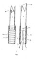
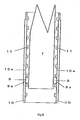
- the stick-type cosmetic container in the related art includes, for example, an outer cylinder 10, a sleeve 2 and an inner container 7 filled with the stick-type cosmetic with an outer decorative cylinder and a lid removed, as shown in Fig. 1 .
- the right drawing is a cross-sectional view substantively showing only the inner container 7 (the stick-type cosmetic is not shown), and the left drawing is a cross-sectional view showing a state in which only the sleeve 2 is removed.
- a small projection 8 is provided on the lower portion of the outer surface of the inner container 7, and an inner container guiding groove 3 is formed on the sleeve 2, and a helical groove 11 is formed on the inner surface of the outer cylinder 10.
- the small projection 8 on the inner container 7 moves upward and downward along the inner container guiding groove 3 on the sleeve 2 in accordance with the rotation of the helical groove 11 on the outer cylinder 10, and the stick-type cosmetic is projected and retracted accordingly.
- the small projection 8 of the inner container 7 moves upward and downward along the inner container guiding groove 3 of the sleeve 2 in accordance with rotation of the outer cylinder 10.
- the inner container 7 finally drops out of the sleeve 2, and thus it is necessary to limit the movement of the small projection 8 on the inner container 7 to a certain range. Therefore, in the stick-type cosmetic container in the related art, the inner container 7 is prevented from being dropped out by closing both ends of the inner container guiding groove 3 or by avoiding formation of the helical groove 11 to the end of the inner surface of the outer cylinder.
- the stick-type cosmetic container in the related art having such structure described above, has no problem when it is used as a disposable container.
- refilling or replacing it is very inconvenient to use.
- the inner container is configured not to be dropped out, replacement of the inner container itself has to be done after disassembling the cosmetic container once.
- US 5,988,917 describes a cosmetic stick dispenser. Lateral recesses in guiding grooves function to lock the inner container in a fully retracted position.
- the present inventors completed the present invention from such idea that both of refilling and replacing, and prevention of dropping of the inner container can be realized simultaneously by utilizing such characteristic that the inner container moves upward and downward along one of the inner container guiding groove by the helical groove formed on the inner surface of the outer cylinder.
- the present invention provides a stick-type cosmetic container including an outer cylinder, a sleeve, and an inner container, in which the stick-type cosmetic can be filled, wherein a small projection formed on the inner container is guided along an inner container guiding groove formed on the sleeve, and is moved upward and downward by a helical groove formed on the inner surface of the outer cylinder for projecting and retracting the stick-type cosmetic filled in the inner container, characterized in that the lower end of the inner container guiding groove formed on the sleeve is opened and a retaining mechanism of the small projection is provided on the lower portion of the inner container guiding groove, as further defined in claim 1.
- the present invention also provides a method of preparing the stick-type cosmetic wherein the stick-type cosmetic container described above is used and the cosmetic is filled from the bottom portion of the container.
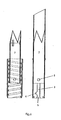
- Fig. 2 is a drawing showing the structure of a stick-type cosmetic container not covered by the claims.
- the drawing on the right side is a cross-sectional view substantively showing only an inner container, and the drawing on the left side is a cross-sectional view showing a state in which only a sleeve is removed (however, the stick-type cosmetic is not shown).
- reference numeral 1 designates the stick-type cosmetic container
- reference numeral 2 designates the sleeve
- reference numeral 3 designates an inner container guiding groove
- reference numeral 4 designates a small projection storage recess
- reference numeral 5 designates a guiding groove end
- reference numeral 6 designates an inner container stopper
- reference numeral 7 designates an inner container
- reference numeral 8 designates a small projection
- reference numeral 9 designates a cosmetic holding projection
- reference numeral 10 designates an outer cylinder
- reference numeral 11 designates a helical groove, respectively.
- the stick-type cosmetic container 1 (not covered by claim 1), basically includes the outer cylinder 10 formed with the helical groove 11 formed on the inner surface thereof, the sleeve 2, and the inner container 7 for accommodating the stick-type cosmetic as in the related art described in conjunction with Fig. 1 , it differs in the shape of the sleeve and the fact that the helical groove 11 is formed to the end.
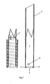
- the sleeve 2 shown in Fig. 3 differs from the sleeve used in the stick-type cosmetic container in the related art in that the inner container guiding groove 3 of the sleeve 2 is opened at the lower end 5, in that the small projection storage recess 4 is provided at the lower portion of the inner container guiding groove 3, and in that the inner container stopper 6 is provided at the lower portion of the sleeve 2.
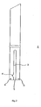
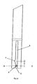
- FIG. 4 A cross-section of the inner container 7 used in combination therewith is shown in Fig. 4 .
- the inner container has a cylindrical shape pointed only at the distal end, and includes the cosmetic holding projection 9 at the boundary between the pointed portion and the cylindrical portion for holding the filled stick-type cosmetic in the inner container 7.
- the small projection 8 of small cylindrical shape is provided at the lower portion of the cylindrical portion.
- the mechanism in which the inner container 7 does not drop out through the lower portion although the lower end 5 of the inner container guiding groove 3 is opened, and the helical groove 11 of the outer cylinder 10 is formed to the end is as follows.
- the helical groove 11 formed on the inside of the outer cylinder 10 provides a force to the small projection 8 of the inner container 7 in the lower left direction.
- the small projection 8 is guided by the inner container guiding groove 3 of the sleeve 2, it cannot be moved leftward, and thus moves only downward.
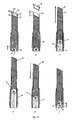
- Fig. 5 shows this state of movement.
- the small projection 8 shown by dotted circles is exerted with a force in the lower left direction by the helical groove 11 shown by the oblique lines.
- Fig. 6 shows the midstage of this movement in the same manner as Fig. 2 (however, the outer cylinder portion is omitted in the drawing on the right side).
- the inner container stopper 6 when the inner container stopper 6 is provided at the lower end of the sleeve 2, it serves as a resistance with respect to the descending inner container 7, and hence the force acting on the small projection 8 exerted from the right side is increased, and thus the small projection 8 can easily enter into the small projection storage recess 4.
- the inner container stopper 6 may not only be the one which completely stop the inner container 7, but also be the one that generates a resistance to the downward movement when in contact. For example, it can be provided by forming a small projection of a convex shape on the inner side of the lower end of the sleeve 2.
- Means for bringing the part of the top surface 8a of the small projection 8 into contact with the inner surface 10a of the outer cylinder 10 includes a method of setting down the center portion of the top surface 8a and allowing only the peripheral portion to come in contact therewith, or a method of providing a rib at the center and allowing only the rib to come into contact therewith.
- the outer cylinder 10 may be rotated rightward, in contrast to the means described above.
- the small projection 8 stored and held in the small projection storage recess 4 receives a force in the upper right direction by the force of the helical groove 11 formed on the outer cylinder 10, and is moved upward along the right end of the inner container guiding groove 3, and then the inner container 7 also moves upward correspondingly.
- the inner container 7 moves upward and downward in the sleeve 2 without dropping out.
- the stick-type cosmetic filled in the inner container 7 has used up, it can easily be replaced together with the inner container 7 by following means.
- the inner container 7 is moved to the lowermost position, and the small projection 8 is stored in the small projection storage recess 4. Then, by suitable means such as the usage of a jig, the small projection 8 on the inner container 7 is moved from the small projection storage recess 4 to the position shown by the circle of the double-dashed line in Fig. 5 .
- the lower end 5 of the inner container guiding groove 3 is opened, and thus the spent stick-type cosmetic can easily be taken out together with the inner container 7 by surmounting the resistance of the inner container stopper 6 by the operation of the jig.
- the stick-type cosmetic container 1 it is possible to fill the stick-type cosmetic in the inner container 7 in advance and mounting it in the container 1. However, it is also possible to mount the inner container 7 without having the stick-type cosmetic filled therein into the stick-type cosmetic container 1 and then filling the cosmetic in the melted state from the bottom of the cosmetic container 1 into the sleeve 2 or the inner container 7 to a predetermined level and making it solid by cooling or the like to prepare the stick-type cosmetic.
- the shape of the sleeve 2 of the stick-type cosmetic container 1 suitable for the preparing method of the latter is shown in Fig. 10 .
- the sleeve 2 shown in Fig. 10 further includes a stop point 14 at the lower portion of the small projection storage recess 4 formed on the inner container guiding groove 3 ( here, the small projection 8 is placed at the position marked with a hatched circle in the drawing when being filled) .
- Fig. 11 is a partial enlarged drawing showing the positional relation between the small projection storage recess 4 and the stop point 14. As shown, two small projections 14a are provided continuously at the lower portion of the small projection storage recess 4 in the inner container guiding groove 3, and the portion interposed between the projections 14a is used as the stop point 14.
- Reference sign "X" designates the distance between the center of the small projection storage recess 4 and the center of the stop point 14.
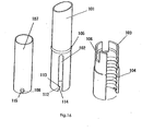
- the sleeve 2 is used with sealing device 15 shown in Fig. 12 , which is to be mounted to the opening thereof, and is capable of bringing the distal end of the sleeve and the distal end surface of the stick-type cosmetic flush with each other.
- the stop point 14 which is capable of fixing the small projection 8 temporarily is provided on the inner container guide groove 3 of the sleeve 2 downwardly of the small projection storage recess 4, and the sealing device 15 is mounted to the opening of the sleeve 2 when filling and molding the cosmetic.
- the positional relation between the distal end of the sleeve and the distal end surface of the cosmetic can be controlled freely and aligned by providing inward setbacks on the sealing device 15 corresponding to the interval between the small projection storage recess 4 and the stop point 14.
- Fig. 12 is an embodiment of the sealing device used for the above-described object, in which A is a perspective view and B is a cross-sectional view.
- reference numeral 15a designates an insertion portion
- reference numeral 15b designates a fitting portion
- reference numeral 15c designates an air hole.
- Fig. 13 shows an example of flow including the steps of filling the cosmetic in the stick-type cosmetic container 1 using the sleeve 2 shown in Fig. 10 and Fig. 11 and the stick-type cosmetic container 1 including the sealing device 15 shown in Fig. 12 to prepare the stick-type cosmetic, inspecting the stick-type cosmetic by bringing it up, and returning the cosmetic into the cosmetic container 1.
- the sealing device 15 is placed on an opening 2a of the sleeve in a state with the small projection 8 (black portion in Fig. 13 ) stored in the stop point 14, and the opening 2a of the sleeve is clamped between the insertion portion 15a and the fitting portion 15b of the sealing device 15 for fixing and sealing. Subsequently, by inverting the cosmetic container 1 so as to be upside down, and filling the stick-type cosmetic in the melted state from the bottom thereof, the cosmetic can be filled in the hatched portion, and may be cooled and solidified so that the stick-type cosmetic 16 is formed and prepared (A in Fig. 13 ).
- the stick-type cosmetic 16 is obtained in a state in which the portion of the sleeve on the distal end side is not filled with the cosmetic by the length Y (See the drawing B). Then when the outer cylinder 10 is rotated rightward, the small projection 8 moves away from the stop point 14 and moves along the right end of the inner container guiding groove 3 upward without being stored in the small projection storage recess 4 positioned on the left side of the guiding groove 3. At this time, the stick-type cosmetic 16 moves away from the surface of the sleeve 2, moves upward in the state of being fixed to the inner container 7, and is brought up from the sleeve opening 2a. (See the drawing C. An arrow indicates the direction in which the stick-type cosmetic 16 advances. It is the same in the drawing E).
- the stick-type cosmetic 16 is inspected in the state of being bought up to the maximum (See the drawing D). After the inspection, by rotating the outer cylinder 10 toward the left, the small projection 8 moves downward along the left end of the inner container guiding groove 3, and the stick-type cosmetic 16 also moved downward according to the movement of the inner container 7 (See the drawing E). Then, the small projection 8 is finally stored and held in the small projection storage recess 4 provided at the lower left of the guiding groove 3 (See the drawing F).
- the position of the small projection 8 (at the stop point 14) when starting the filling operation differs from the position of the small projection 8 (in the small projection storage recess 4) at the time of shipping.
- the distal end surface of the stick-type cosmetic 16 and the opening 2a of the sleeve preferably coincide with each other when the small projection 8 is stored in the small projection storage recess 4.
- the sealing device 15 which is set back inwardly is used, the cosmetic does not leak from the edge of the sleeve opening 2a when filling the cosmetic, and hence the problem of stain at the opening 2a may be avoided.
- the shape of the stop point 14 is not limited as long as it can stop the small projection 8 when filling the cosmetic.
- the shape which fixes the small projection 8 and, simultaneously, allows it to move easily when moving upward along the right end of the inner container guiding groove 3 is preferable.
- the small projection 8 is subjected to the force in the right upward direction, so that the stick-type cosmetic 16 does not rotate by itself when being brought up, and the upwardmovement along the right end of the inner container guiding groove 3 is done smoothly.
- the embodiment described above is preferable. Since the cosmetic filled in the stick-type cosmetic container 1 slightly shrinks when being cooled and solidified, the outer surface of the cosmetic normally comes away from the inner surface of the sleeve. However, the cosmetic and the sleeve may stay in tight contact on rare occasion. In such a state, when a rotational force is exerted to the cosmetic in order to bring up the stick-type cosmetic by rotating the outer cylinder 10 rightward, the cosmeticmay disadvantageously be broken since the sleeve 2 and the cosmetic are in tight contact with each other. On the other hand, by employing the stop point 14 in the configuration as described above, the small projection 8 received only the upward force, and thus the cosmetic can be peeled off the inner surface of the sleeve without rotating the stick-type cosmetic when being brought up.
- the stop point 14 is preferably formed by machining the lower portion of the small projection storage recess 4 in the inner container guiding groove 3 into the configuration shown in Fig. 10 and Fig. 11 as described in the embodiment described above. Though not shown, it is also possible to form the lower end of the small projection storage recess 4 so as to overhang into the inner container guiding groove 3. In this configuration as well, the small projection 8 can easily be moved along the right end of the inner container guiding groove 3.
- the shape of the sealing device 15 in the present embodiment is not specifically limited as long as it can close the opening of the sleeve 2.
- the length Y preferably coincides with the distance X between the small projection storage recess 4 and the stop point 14.
- the suitable air hole 15c for allowing air ventilation air can easily be flown into the gap between the inner surface of the sleeve 2 and the cosmetic when the cosmetic shrinks in response to cooling at the time of filling and molding, and hence peeling off of the cosmetic is preferably performed smoothly.
- the number of the air hole 15c is not specifically limited, forming three or four air holes 15c is preferable in view of usability and manufacturability of the sealing device 15.
- the position of the small projection 8 at the stop point 14 shown in Fig. 11 is slightly displaced in the direction of rotation from the position of the small projection storage recess 4 when the stick-type cosmetic is stored.
- This configuration has no problem as long as the shape of the distal end of the stick-type cosmetic is rotational symmetry with respect to the centerline of the stick-type cosmetic.
- the direction of the end surface of the opening of the sleeve 2 and the direction of the end surface of the stick-type cosmetic when the stick-type container is stored do not coincide due to the above-described displacement in the direction of rotation, which may result in rough finish.
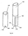
- the bottom 12 may be formed, for example, into the shape shown in Fig. 14 , and adhered with a sticker in normal use.
- the size of the hole on the bottom 12 may be slightly larger than the inner container 7, and a notch 13 maybe formed so as to correspond to the small projection 8.
- reference numeral 101 designates a sleeve
- reference numeral 102 designates an inner container guiding groove
- reference numeral 103 designates an outer cylinder
- reference numeral 104 designates a helical groove
- reference numeral 105 designates an annular projection
- reference numeral 106 designates a recess groove
- reference numeral 107 designates an inner container
- reference numeral 112 designates a locking projection
- reference numeral 113 designates a locking surface
- reference numeral 114 designates a gentle slope
- reference numeral 115 designates a locking notch.
- the retaining mechanism including the locking projection 112 formed at the lower portion of the inner container guiding groove 102 and the locking notch 115 formed at the position corresponding to the locking projection 112 of the small projection 108 is provided.
- the locking projection 112 is formed to make the width of the inner container guiding groove 102 smaller than the diameter of the small projection 108 on the inner container 107, and is formed on the side surface toward which the small projection 108 is pushed against by the helical groove 104 when the inner container 107 is moved downward (the left side in Fig. 15 ) .
- the upper surface of the locking projection 112 is formed with a substantially horizontal locking surface 113 so as to fit to the locking notch 115 of the small projection 108. Since a force to push the small projection 108 toward the left is generated when the small projection 108 is moved downward, the small projection 108 cannot climb over the locking projection 112, and hence the inner container 107 is prevented from dropping out of the sleeve 101.
- the lower surface 114 of the locking projection 112 is preferably a gentle slope so that the small projection 108 can easily climb over the locking projection 112 by broadening the width of the inner container guiding groove 102 when setting the inner container 107 to the sleeve 101.
- the sleeve 101 and the outer cylinder 103 it is necessary to allow the sleeve 101 and the outer cylinder 103 to rotate freely but keep them not to be dropped out easily.
- a mechanism in which the annular projection 105 formed into a ring-shape at the substantially center of the sleeve 101 is clamped in the recess groove 106 formed on top of the outer cylinder 103 as shown in Fig. 16 may be provided.
- the small projection 108 in this configuration is not specifically limited, it is preferable to form it into a small column in order to ensure fitting between the locking notch 115 and the locking projection 112.
- the distal end of the locking surface 113 may be raised in order to enhance the effect of holding the small projection 108.
- Fig. 19 to Fig. 21 show the configuration in which the locking projections 112 are provided at two levels.
- the single small projection 108 is provided on the inner container 107, while the upper locking projection 112a and the lower locking projection 112b are provided at two levels aligned in the vertical direction, and the respective locking projections are formed respectively with locking surfaces 113a, 113b and gentle slopes 114a, 114b.
- the cosmetic can be filled from the bottom finely by the following procedure.
- the inner container 107 is brought down to the position where the small projection 108 is locked with the lower locking projection 112b, then sealing device (not shown) is placed on the opening at the distal end of the sleeve 101, and then the sealing device is fixed and sealed.
- the cosmetic can be filled to the predetermined level, and may be cooled and solidified to mold and prepare the stick-type cosmetic.
- the stick-type cosmetic is solidified and molded in this manner.
- the sealing device for sealing the opening at the distal end of the sleeve 101 having a length corresponding to the distance between the two locking projections is employed, the sealing device is removed once, then the inner container 107 is brought upward until it passes over the position where the small projection 108 is locked with the upper locking projection 112a for investigating whether or not there is abnormality in the solidified cosmetic, and then is again brought down. Consequently, the small projection 108 is locked with the upper locking projection 112a as shown in Fig. 20 , and is stopped and held there. Since the distal end surface of the stick-type cosmetic at this time substantially coincides with the distal end of the sleeve and, in addition, the surface thereof is as smooth as the surface of the sealing device, it can be provided as a final product.
- Fig. 21 Examples of the sleeve 101 and the inner container 107 used in this configuration are shown in Fig. 21 .
- a configuration in which two small projections including an upper small projection 108a and a lower small projection 108b are provided as small projections including the locking notches 115 as shown in Fig. 22 and Fig. 24 may be provided.
- the operational mechanism in this configuration is basically the same as the configurations described above, and when filling the cosmetic into the container, the inner container 107 is brought down to the position where the upper small projection 108a is locked with the locking projection 112 as shown in Fig. 22 , and the sealing device (not shown) is placed on the opening at the distal end of the sleeve 101, and the sealing device is fixed and sealed. Subsequently, by inverting the cosmetic container to be upside down, and filling the stick-type cosmetic in the melted state from the bottom, the cosmetic can be filled to the predetermined level, and may be cooled and solidified to mold and prepare the stick-type cosmetic.
- the sealing device having a length corresponding to the distance between the two small projections is used when solidifying and molding
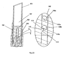
- the sealing device is removed, the inner container 107 is brought upward until it passes over the position where the lower small projection 108b is locked with the locking projection 112 once for investigating whether or not there is abnormality in the solidified cosmetic, and then is again brought down. Consequently, the lower small projection 108b is locked with the locking projection 112 as shown in Fig. 23 , and is stopped and held there. Since the distal end surface of the stick-type cosmetic at this time substantially coincides with the distal end of the sleeve and, in addition, the surface thereof is as smooth as the surface of the sealing device, it can be provided as a final product.
- Fig. 24 Examples of the sleeve 101 and the inner container 107 used in this configuration is shown in Fig. 24 .
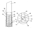
- a recess 120 may be formed by removing part of the inner container guiding groove 102 at the position corresponding to the locking projection 112 on the opposite side as shown in Fig. 25 and Fig. 26 .
- the recess 120 is formed for facilitating passage of the small projection 108 through the portion of the locking projection 112 when moving the inner container 107 upward, and thus the inner container 107 can easily be mounted into the sleeve 101.
- the stick-type cosmetic container of the present invention thus obtained can be prepared as substantially the same products as the stick-type cosmetic container which has been provided in the related art in material, size and shape except for the shape of the sleeve 2 or 101, the fact that the helical groove 11 or 111 on the outer cylinder is formed to the end, and the shape of the small projection according to the second embodiment.
- the distal end of the inner container may not be the pointed shape, but may be other shapes, and materials for the sleeve 2 or 101, the inner container 7 or 107, and the outer cylinder 10 or 110 may be various types of metal or plastic as in the related art.
- the inner container does not drop out when in use, but can easily be replaced by the use of a simple jig when the stick-type cosmetic is completely used.
Landscapes
- Containers And Packaging Bodies Having A Special Means To Remove Contents (AREA)
- Cosmetics (AREA)
Description
- The present invention relates to a stick-type cosmetic container and, more specifically, to a stick-type cosmetic container in which only a stick-type cosmetic filled therein can easily be replaced.
- A stick-type cosmetic container in which a stick-type cosmetic filled therein is projected and retracted by rotating an outer cylinder is widely used as a container for lipsticks and other cosmetics such as lip cream and concealer because of its usability or some other reasons.
- The stick-type cosmetic container in the related art includes, for example, an
outer cylinder 10, asleeve 2 and aninner container 7 filled with the stick-type cosmetic with an outer decorative cylinder and a lid removed, as shown inFig. 1 . InFig. 1 , the right drawing is a cross-sectional view substantively showing only the inner container 7 (the stick-type cosmetic is not shown), and the left drawing is a cross-sectional view showing a state in which only thesleeve 2 is removed. - A
small projection 8 is provided on the lower portion of the outer surface of theinner container 7, and an innercontainer guiding groove 3 is formed on thesleeve 2, and ahelical groove 11 is formed on the inner surface of theouter cylinder 10. Thesmall projection 8 on theinner container 7 moves upward and downward along the innercontainer guiding groove 3 on thesleeve 2 in accordance with the rotation of thehelical groove 11 on theouter cylinder 10, and the stick-type cosmetic is projected and retracted accordingly. - In this manner, the
small projection 8 of theinner container 7 moves upward and downward along the innercontainer guiding groove 3 of thesleeve 2 in accordance with rotation of theouter cylinder 10. However, if it moves endlessly, theinner container 7 finally drops out of thesleeve 2, and thus it is necessary to limit the movement of thesmall projection 8 on theinner container 7 to a certain range. Therefore, in the stick-type cosmetic container in the related art, theinner container 7 is prevented from being dropped out by closing both ends of the innercontainer guiding groove 3 or by avoiding formation of thehelical groove 11 to the end of the inner surface of the outer cylinder. - The stick-type cosmetic container in the related art, having such structure described above, has no problem when it is used as a disposable container. However, when refilling or replacing is considered, it is very inconvenient to use. In other words, since the inner container is configured not to be dropped out, replacement of the inner container itself has to be done after disassembling the cosmetic container once.
-
US 5,988,917 describes a cosmetic stick dispenser. Lateral recesses in guiding grooves function to lock the inner container in a fully retracted position. - In recent years, in accordance with widespread movement of resource saving or recycling, cosmetic containers which can be refilled or replaced are preferred. However, as regards the stick-type cosmetic container, the container in which only the stick-type cosmetic can be replaced has not been provided as a matter of fact in above-mentioned reasons.
- Therefore, it is an object of the present invention to provide a stick-type cosmetic container in which refilling and replacement can easily be performed, while the risk of dropping of the inner container in normal use can be avoided.
- Having been dedicated to studying means for solving the problems described above, the present inventors completed the present invention from such idea that both of refilling and replacing, and prevention of dropping of the inner container can be realized simultaneously by utilizing such characteristic that the inner container moves upward and downward along one of the inner container guiding groove by the helical groove formed on the inner surface of the outer cylinder.
- In other words, the present invention provides a stick-type cosmetic container including an outer cylinder, a sleeve, and an inner container, in which the stick-type cosmetic can be filled, wherein a small projection formed on the inner container is guided along an inner container guiding groove formed on the sleeve, and is moved upward and downward by a helical groove formed on the inner surface of the outer cylinder for projecting and retracting the stick-type cosmetic filled in the inner container, characterized in that the lower end of the inner container guiding groove formed on the sleeve is opened and a retaining mechanism of the small projection is provided on the lower portion of the inner container guiding groove, as further defined in
claim 1. - The present invention also provides a method of preparing the stick-type cosmetic wherein the stick-type cosmetic container described above is used and the cosmetic is filled from the bottom portion of the container.
-
-
Fig. 1 is a drawing showing a structure of a stick-type cosmetic container in the related art. -
Fig. 2 is a drawing showing a structure of a stick-type cosmetic container. An inner container is located at the uppermost position. -
Fig. 3 is a drawing showing a configuration of a sleeve used in the stick-type cosmetic container shown inFig. 2 . -
Fig. 4 is a drawing showing the shape of the inner container used in the stick-type cosmetic container shown inFig. 2 . -
Fig. 5 is a drawing showing the movement of a small projection and the relation between an inner container guiding groove and a small projection storage recess. -
Fig. 6 is a drawing showing a state in which the inner container is moved partway downward in the stick-type cosmetic container shown inFig. 2 . -
Fig. 7 is a drawing showing a state in which the inner container is moved downward and the small projection is stored in the small projection storage recess in the stick-type cosmetic container shown inFig. 2 . -
Fig. 8 is a drawing of a stick-type cosmetic container according to the present invention showing a configuration in which the top surface of the small projection provided on the inner container and the inner surface of an outer cylinder come into contact with each other. -
Fig. 9 is a cross-sectional view showing a contact state between the top surface of the small projection and the inner surface of the outer cylinder inFig.8 . -
Fig. 10 is a drawing showing a configuration in which a stop point is provided on the sleeve. -
Fig. 11 is a partly enlarged drawing showing the positional relation between the small projection storage recess and the stop point in a state in which the stop point is provided on the sleeve. -
Fig. 12 is a drawing showing an embodiment of a sealing device. -
Fig. 13 is a drawing showing an example of a flow of using a stick-typecosmetic container 1, filling cosmetic into the stick-typecosmetic container 1, and then conducting a test by bringing the stick-type cosmetic outwardly of the container, and returning the cosmetic again into the container. -
Fig. 14 is a drawing showing an example of the shape of the bottom. -
Fig. 15 is a drawing showing the structure of an embodiment of the stick-type cosmetic container of the present invention. The inner container is located at the lowermost position. -
Fig. 16 is a drawing showing the shapes of the sleeve, the inner container, and the outer cylinder used in the stick-type cosmetic container shown inFig. 15 . -
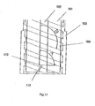
Fig. 17 is a drawing showing the relation between the angle of a helical groove and the angle of a locking surface in the embodiment shown inFig. 15 . -
Fig. 18 is a drawing showing a configuration in which the distal end of locking surface is moved upward (the state in which the angle formed between the guiding groove and the locking surface is an acute angle). -
Fig. 19 is a drawing showing the structure of an embodiment in which the locking projections are provided at two levels. The inner container is located at the lowermost position. -
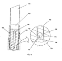
Fig. 20 is a drawing showing a state in which the inner container is at the lowermost position in normal use in the embodiment shown inFig. 19 . -
Fig. 21 is a drawing showing the shapes of the sleeve and the inner container used in the stick-type cosmetic container according to the embodiment shown inFig. 19 . -
Fig. 22 is a drawing showing the structure in which two small projections are provided. The inner container is located at the lowermost position. -
Fig. 23 is a drawing showing a state in which the inner container is at the lowermost position in the normal use in the embodiment shown inFig. 22 . -
Fig. 24 is a drawing showing the shapes of the sleeves and the inner container used in the stick-type cosmetic container in the embodiment shown inFig. 22 . -
Fig. 25 is a drawing showing a configuration in which part of the inner container guiding groove is notched at the position corresponding to the position of the locking projection on the opposite side. -
Fig. 26 is a drawing showing the shapes of the sleeves and the inner container used in the stick-type cosmetic container in the embodiment shown inFig. 25 . - Hereinafter, referring now to the drawings showing some embodiments of the present invention, the present invention will be described further in detail.
-
Fig. 2 is a drawing showing the structure of a stick-type cosmetic container not covered by the claims. The drawing on the right side is a cross-sectional view substantively showing only an inner container, and the drawing on the left side is a cross-sectional view showing a state in which only a sleeve is removed (however, the stick-type cosmetic is not shown). In the drawing,reference numeral 1 designates the stick-type cosmetic container,reference numeral 2 designates the sleeve,reference numeral 3 designates an inner container guiding groove,reference numeral 4 designates a small projection storage recess,reference numeral 5 designates a guiding groove end,reference numeral 6 designates an inner container stopper,reference numeral 7 designates an inner container,reference numeral 8 designates a small projection,reference numeral 9 designates a cosmetic holding projection,reference numeral 10 designates an outer cylinder, andreference numeral 11 designates a helical groove, respectively. - Though the stick-type cosmetic container 1 (not covered by claim 1), basically includes the
outer cylinder 10 formed with thehelical groove 11 formed on the inner surface thereof, thesleeve 2, and theinner container 7 for accommodating the stick-type cosmetic as in the related art described in conjunction withFig. 1 , it differs in the shape of the sleeve and the fact that thehelical groove 11 is formed to the end. - In other words, as seen in the shape of the
sleeve 2 shown inFig. 3 , it differs from the sleeve used in the stick-type cosmetic container in the related art in that the innercontainer guiding groove 3 of thesleeve 2 is opened at thelower end 5, in that the smallprojection storage recess 4 is provided at the lower portion of the innercontainer guiding groove 3, and in that theinner container stopper 6 is provided at the lower portion of thesleeve 2. - A cross-section of the
inner container 7 used in combination therewith is shown inFig. 4 . The inner container has a cylindrical shape pointed only at the distal end, and includes thecosmetic holding projection 9 at the boundary between the pointed portion and the cylindrical portion for holding the filled stick-type cosmetic in theinner container 7. In addition, at the lower portion of the cylindrical portion, thesmall projection 8 of small cylindrical shape is provided. - In the stick-type cosmetic container 1 (not covered by claim 1), the mechanism in which the
inner container 7 does not drop out through the lower portion although thelower end 5 of the innercontainer guiding groove 3 is opened, and thehelical groove 11 of theouter cylinder 10 is formed to the end is as follows. - By rotating the
outer cylinder 10 of the stick-typecosmetic container 1 in the state shown inFig. 2 while holding thesleeve 2 to the left, thehelical groove 11 formed on the inside of theouter cylinder 10 provides a force to thesmall projection 8 of theinner container 7 in the lower left direction. However, since thesmall projection 8 is guided by the innercontainer guiding groove 3 of thesleeve 2, it cannot be moved leftward, and thus moves only downward. -
Fig. 5 shows this state of movement. In the drawing, thesmall projection 8 shown by dotted circles is exerted with a force in the lower left direction by thehelical groove 11 shown by the oblique lines. However, since the leftward movement is restrained by the innercontainer guiding groove 3, it moves downward along the left end of the innercontainer guiding groove 3.Fig. 6 shows the midstage of this movement in the same manner asFig. 2 (however, the outer cylinder portion is omitted in the drawing on the right side). - By rotating the outer cylinder leftward in this manner, the
small projection 8 is moved downward, and theinner container 7 also moves downward correspondingly. However, since the smallprojection storage recess 4 is provided at the position near thelower end 5 of the innercontainer guiding groove 3, a leftward force, which has been restrained by the left end of the innercontainer guiding groove 3 until that moment, is exerted, and thus thesmall projection 8 is stored and held in the smallprojection storage recess 4, not at the position shown by a circle of the chain double-dashed line inFig. 5 . Therefore, since thesmall projection 8 is restrained in the smallprojection storage recess 4, it cannot be moved further downward even when an attempt is made to further rotate theouter cylinder 10.Fig. 7 shows this state in the same manner asFig. 2 (however, the outer cylindrical portion is omitted in the drawing on the right side). - In addition, when the
inner container stopper 6 is provided at the lower end of thesleeve 2, it serves as a resistance with respect to the descendinginner container 7, and hence the force acting on thesmall projection 8 exerted from the right side is increased, and thus thesmall projection 8 can easily enter into the smallprojection storage recess 4. Theinner container stopper 6 may not only be the one which completely stop theinner container 7, but also be the one that generates a resistance to the downward movement when in contact. For example, it can be provided by forming a small projection of a convex shape on the inner side of the lower end of thesleeve 2. - As another means for allowing easy entrance of the
small projection 8 into the smallprojection storage recess 4, there is a method of bringing at least part of thetop surface 8a of thesmall projection 8 and theinner surface 10a of theouter cylinder 10 into contact with each other as shown inFig. 8 . According to this method, when thesmall projection 8 moves upward and downward in the innercontainer guiding groove 3, at least part of thetop surface 8a of thesmall projection 8 and theinner surface 10a of theouter cylinder 10 keep constantly in contact with each other and hence a resistance is generated as shown inFig. 9 . Therefore, a force acting on thesmall projection 8 exerted from the right side is increased and thus it can easily enter into the smallprojection storage recess 4. When implementing the present embodiment, it is preferable to provide theouter cylinder 10 having the same diameter from the top to the bottom, and in this case, it is preferable to reduce a thickness t of theouter cylinder 10 to provide resiliency. Means for bringing the part of thetop surface 8a of thesmall projection 8 into contact with theinner surface 10a of theouter cylinder 10 includes a method of setting down the center portion of thetop surface 8a and allowing only the peripheral portion to come in contact therewith, or a method of providing a rib at the center and allowing only the rib to come into contact therewith. - Subsequently, in order to bring the stick-type cosmetic up from the stick-type
cosmetic container 1 in the state shown inFig. 7 (to move upward), theouter cylinder 10 may be rotated rightward, in contrast to the means described above. Thesmall projection 8 stored and held in the smallprojection storage recess 4 receives a force in the upper right direction by the force of thehelical groove 11 formed on theouter cylinder 10, and is moved upward along the right end of the innercontainer guiding groove 3, and then theinner container 7 also moves upward correspondingly. - With this mechanism, the
inner container 7 moves upward and downward in thesleeve 2 without dropping out. However, when the stick-type cosmetic filled in theinner container 7 has used up, it can easily be replaced together with theinner container 7 by following means. - In a first place, the
inner container 7 is moved to the lowermost position, and thesmall projection 8 is stored in the smallprojection storage recess 4. Then, by suitable means such as the usage of a jig, thesmall projection 8 on theinner container 7 is moved from the smallprojection storage recess 4 to the position shown by the circle of the double-dashed line inFig. 5 . When it is moved to this position, since thelower end 5 of the innercontainer guiding groove 3 is opened, and thus the spent stick-type cosmetic can easily be taken out together with theinner container 7 by surmounting the resistance of theinner container stopper 6 by the operation of the jig. - Subsequently, replacement of the stick-type cosmetic is completed by inserting a new stick-type cosmetic filled in the inner container from the bottom of the stick-type
cosmetic container 1 and storing thesmall projection 8 into the smallprojection storage recess 4 by the use of the jig again. - In the stick-type
cosmetic container 1, it is possible to fill the stick-type cosmetic in theinner container 7 in advance and mounting it in thecontainer 1. However, it is also possible to mount theinner container 7 without having the stick-type cosmetic filled therein into the stick-typecosmetic container 1 and then filling the cosmetic in the melted state from the bottom of thecosmetic container 1 into thesleeve 2 or theinner container 7 to a predetermined level and making it solid by cooling or the like to prepare the stick-type cosmetic. - The shape of the
sleeve 2 of the stick-typecosmetic container 1 suitable for the preparing method of the latter is shown inFig. 10 . - The
sleeve 2 shown inFig. 10 further includes astop point 14 at the lower portion of the smallprojection storage recess 4 formed on the inner container guiding groove 3 ( here, thesmall projection 8 is placed at the position marked with a hatched circle in the drawing when being filled) .Fig. 11 is a partial enlarged drawing showing the positional relation between the smallprojection storage recess 4 and thestop point 14. As shown, twosmall projections 14a are provided continuously at the lower portion of the smallprojection storage recess 4 in the innercontainer guiding groove 3, and the portion interposed between theprojections 14a is used as thestop point 14. Reference sign "X" designates the distance between the center of the smallprojection storage recess 4 and the center of thestop point 14. - The
sleeve 2 is used with sealingdevice 15 shown inFig. 12 , which is to be mounted to the opening thereof, and is capable of bringing the distal end of the sleeve and the distal end surface of the stick-type cosmetic flush with each other. - In other words, in preparing the stick-type cosmetic, when the cosmetic was filled using the normal cover, there arose the problem in that the cosmetic leaks from the gap of the cover, and attached to the edge of the opening, which lowered the commercial value.
- Such drawback can be resolved by filling the cosmetic so as not to reach the opening of the sleeve, that is, by using a cap which is set back inwardly. However, when the stick-type cosmetic is not filled up to the level of the opening of the sleeve when starting to use, the consumer may think that the filling amount is not sufficient, which is not commercially desirable as a commodity design.
- In order to cope with such problems, the
stop point 14 which is capable of fixing thesmall projection 8 temporarily is provided on the innercontainer guide groove 3 of thesleeve 2 downwardly of the smallprojection storage recess 4, and the sealingdevice 15 is mounted to the opening of thesleeve 2 when filling and molding the cosmetic. In addition, it was found that the positional relation between the distal end of the sleeve and the distal end surface of the cosmetic can be controlled freely and aligned by providing inward setbacks on the sealingdevice 15 corresponding to the interval between the smallprojection storage recess 4 and thestop point 14. -
Fig. 12 is an embodiment of the sealing device used for the above-described object, in which A is a perspective view and B is a cross-sectional view. In the drawings,reference numeral 15a designates an insertion portion,reference numeral 15b designates a fitting portion, and reference numeral 15c designates an air hole. -
Fig. 13 shows an example of flow including the steps of filling the cosmetic in the stick-typecosmetic container 1 using thesleeve 2 shown inFig. 10 andFig. 11 and the stick-typecosmetic container 1 including the sealingdevice 15 shown inFig. 12 to prepare the stick-type cosmetic, inspecting the stick-type cosmetic by bringing it up, and returning the cosmetic into thecosmetic container 1. - In other words, the sealing
device 15 is placed on anopening 2a of the sleeve in a state with the small projection 8 (black portion inFig. 13 ) stored in thestop point 14, and theopening 2a of the sleeve is clamped between theinsertion portion 15a and thefitting portion 15b of the sealingdevice 15 for fixing and sealing. Subsequently, by inverting thecosmetic container 1 so as to be upside down, and filling the stick-type cosmetic in the melted state from the bottom thereof, the cosmetic can be filled in the hatched portion, and may be cooled and solidified so that the stick-type cosmetic 16 is formed and prepared (A inFig. 13 ). - When the sealing
device 15 is removed from theopening 2a of the sleeve after filling and molding of the cosmetic, the stick-type cosmetic 16 is obtained in a state in which the portion of the sleeve on the distal end side is not filled with the cosmetic by the length Y (See the drawing B). Then when theouter cylinder 10 is rotated rightward, thesmall projection 8 moves away from thestop point 14 and moves along the right end of the innercontainer guiding groove 3 upward without being stored in the smallprojection storage recess 4 positioned on the left side of the guidinggroove 3. At this time, the stick-type cosmetic 16 moves away from the surface of thesleeve 2, moves upward in the state of being fixed to theinner container 7, and is brought up from thesleeve opening 2a. (See the drawing C. An arrow indicates the direction in which the stick-type cosmetic 16 advances. It is the same in the drawing E). - The stick-
type cosmetic 16 is inspected in the state of being bought up to the maximum (See the drawing D). After the inspection, by rotating theouter cylinder 10 toward the left, thesmall projection 8 moves downward along the left end of the innercontainer guiding groove 3, and the stick-type cosmetic 16 also moved downward according to the movement of the inner container 7 (See the drawing E). Then, thesmall projection 8 is finally stored and held in the smallprojection storage recess 4 provided at the lower left of the guiding groove 3 (See the drawing F). - In this manner, the position of the small projection 8 (at the stop point 14) when starting the filling operation differs from the position of the small projection 8 (in the small projection storage recess 4) at the time of shipping. In this case, by setting the distance X between the
stop point 14 and the smallprojection storage recess 4 to meet the length of the sealing device 15 (that is, the unfilled portion Y at the distal end), the distal end surface of the stick-type cosmetic 16 and theopening 2a of the sleeve preferably coincide with each other when thesmall projection 8 is stored in the smallprojection storage recess 4. In addition, since the sealingdevice 15 which is set back inwardly is used, the cosmetic does not leak from the edge of thesleeve opening 2a when filling the cosmetic, and hence the problem of stain at theopening 2a may be avoided. - The shape of the
stop point 14 is not limited as long as it can stop thesmall projection 8 when filling the cosmetic. However, the shape which fixes thesmall projection 8 and, simultaneously, allows it to move easily when moving upward along the right end of the innercontainer guiding groove 3 is preferable. With such shape, when bringing up the stick-type cosmetic 16 (moving thesmall projection 8 upward) by rotating theouter cylinder 10 rightward after filling and molding the cosmetic, thesmall projection 8 is subjected to the force in the right upward direction, so that the stick-type cosmetic 16 does not rotate by itself when being brought up, and the upwardmovement along the right end of the innercontainer guiding groove 3 is done smoothly. - Another reason why the embodiment described above is preferable is as follows. Since the cosmetic filled in the stick-type
cosmetic container 1 slightly shrinks when being cooled and solidified, the outer surface of the cosmetic normally comes away from the inner surface of the sleeve. However, the cosmetic and the sleeve may stay in tight contact on rare occasion. In such a state, when a rotational force is exerted to the cosmetic in order to bring up the stick-type cosmetic by rotating theouter cylinder 10 rightward, the cosmeticmay disadvantageously be broken since thesleeve 2 and the cosmetic are in tight contact with each other. On the other hand, by employing thestop point 14 in the configuration as described above, thesmall projection 8 received only the upward force, and thus the cosmetic can be peeled off the inner surface of the sleeve without rotating the stick-type cosmetic when being brought up. - The
stop point 14 is preferably formed by machining the lower portion of the smallprojection storage recess 4 in the innercontainer guiding groove 3 into the configuration shown inFig. 10 andFig. 11 as described in the embodiment described above. Though not shown, it is also possible to form the lower end of the smallprojection storage recess 4 so as to overhang into the innercontainer guiding groove 3. In this configuration as well, thesmall projection 8 can easily be moved along the right end of the innercontainer guiding groove 3. - The shape of the sealing
device 15 in the present embodiment is not specifically limited as long as it can close the opening of thesleeve 2. However, the length Y preferably coincides with the distance X between the smallprojection storage recess 4 and thestop point 14. In addition, like the configuration shown inFig. 12 , by forming thesuitable air hole 15c for allowing air ventilation, air can easily be flown into the gap between the inner surface of thesleeve 2 and the cosmetic when the cosmetic shrinks in response to cooling at the time of filling and molding, and hence peeling off of the cosmetic is preferably performed smoothly. In addition, it is further preferable to employ a capsule-shape, since it can be removed easily. - Though the number of the
air hole 15c is not specifically limited, forming three or fourair holes 15c is preferable in view of usability and manufacturability of the sealingdevice 15. - The position of the
small projection 8 at thestop point 14 shown inFig. 11 is slightly displaced in the direction of rotation from the position of the smallprojection storage recess 4 when the stick-type cosmetic is stored. This configuration has no problem as long as the shape of the distal end of the stick-type cosmetic is rotational symmetry with respect to the centerline of the stick-type cosmetic. However, in the case where the distal end is inclined as shown inFig. 10 , the direction of the end surface of the opening of thesleeve 2 and the direction of the end surface of the stick-type cosmetic when the stick-type container is stored do not coincide due to the above-described displacement in the direction of rotation, which may result in rough finish. In such case (in the configuration shown inFig. 10 ), it is preferable to correct the shape of the sealingdevice 15 to the extent corresponding to such displacement in advance so that both of the surfaces coincide with each other. - In the stick-type
cosmetic container 1, since there are cases inwhich the stick-type cosmetic is taken in and out from the bottom, it is necessary that the bottom is opened to some extent. However, since such state does not present good appearance, the bottom 12 may be formed, for example, into the shape shown inFig. 14 , and adhered with a sticker in normal use. The size of the hole on the bottom 12 may be slightly larger than theinner container 7, and anotch 13 maybe formed so as to correspond to thesmall projection 8. - It will be convenient to mark the product number, the color tone, and the like on the sticker to be adhered on the bottom 12 when purchasing the stick-type cosmetic for replacement.
- The configuration of the small projection retaining mechanism of the stick-type cosmetic container of the invention is shown in
Fig. 15 to Fig. 16 . In the drawings,reference numeral 101 designates a sleeve,reference numeral 102 designates an inner container guiding groove,reference numeral 103 designates an outer cylinder,reference numeral 104 designates a helical groove,reference numeral 105 designates an annular projection,reference numeral 106 designates a recess groove,reference numeral 107 designates an inner container,reference 108 designates a small projection,reference numeral 112 designates a locking projection,reference numeral 113 designates a locking surface,reference numeral 114 designates a gentle slope, andreference numeral 115 designates a locking notch. - In this configuration, the retaining mechanism including the locking
projection 112 formed at the lower portion of the innercontainer guiding groove 102 and the lockingnotch 115 formed at the position corresponding to the lockingprojection 112 of thesmall projection 108 is provided. - The locking
projection 112 is formed to make the width of the innercontainer guiding groove 102 smaller than the diameter of thesmall projection 108 on theinner container 107, and is formed on the side surface toward which thesmall projection 108 is pushed against by thehelical groove 104 when theinner container 107 is moved downward (the left side inFig. 15 ) . The upper surface of the lockingprojection 112 is formed with a substantiallyhorizontal locking surface 113 so as to fit to the lockingnotch 115 of thesmall projection 108. Since a force to push thesmall projection 108 toward the left is generated when thesmall projection 108 is moved downward, thesmall projection 108 cannot climb over the lockingprojection 112, and hence theinner container 107 is prevented from dropping out of thesleeve 101. - It is necessary to define the angle formed between the locking
surface 113 and the upper portion of the inner container guiding groove 102 (angle A in the drawing) smaller than the angle formed between thehelical groove 104 and the upper portion of the inner container guide groove 102 (angle B in the drawing) as shown inFig. 17 . Thelower surface 114 of the lockingprojection 112 is preferably a gentle slope so that thesmall projection 108 can easily climb over the lockingprojection 112 by broadening the width of the innercontainer guiding groove 102 when setting theinner container 107 to thesleeve 101. - In the stick-type cosmetic according to the present invention, it is necessary to allow the
sleeve 101 and theouter cylinder 103 to rotate freely but keep them not to be dropped out easily. In order to do so, for example, a mechanism in which theannular projection 105 formed into a ring-shape at the substantially center of thesleeve 101 is clamped in therecess groove 106 formed on top of theouter cylinder 103 as shown inFig. 16 may be provided. - Though the
small projection 108 in this configuration is not specifically limited, it is preferable to form it into a small column in order to ensure fitting between the lockingnotch 115 and the lockingprojection 112. Alternatively, as shown inFig. 18 , the distal end of the lockingsurface 113 may be raised in order to enhance the effect of holding thesmall projection 108. - In the retaining mechanism described above, it is also possible to provide a plurality of either
small projections 108 or lockingnotches 115 to provide a plurality of holding positions. - For example,
Fig. 19 to Fig. 21 show the configuration in which the lockingprojections 112 are provided at two levels. - In this configuration, the single
small projection 108 is provided on theinner container 107, while theupper locking projection 112a and thelower locking projection 112b are provided at two levels aligned in the vertical direction, and the respective locking projections are formed respectively with lockingsurfaces gentle slopes - In the cosmetic storage container having two locking projections aligned in the vertical direction as described above, the cosmetic can be filled from the bottom finely by the following procedure. When filling the cosmetic into the container, as shown in
Fig. 19 , theinner container 107 is brought down to the position where thesmall projection 108 is locked with thelower locking projection 112b, then sealing device (not shown) is placed on the opening at the distal end of thesleeve 101, and then the sealing device is fixed and sealed. Subsequently, by inverting the cosmetic container so as to be upside down, and filling the stick-type cosmetic in the melted state therein from the bottom, the cosmetic can be filled to the predetermined level, and may be cooled and solidified to mold and prepare the stick-type cosmetic. - The stick-type cosmetic is solidified and molded in this manner. However, when the sealing device for sealing the opening at the distal end of the
sleeve 101 having a length corresponding to the distance between the two locking projections is employed, the sealing device is removed once, then theinner container 107 is brought upward until it passes over the position where thesmall projection 108 is locked with theupper locking projection 112a for investigating whether or not there is abnormality in the solidified cosmetic, and then is again brought down. Consequently, thesmall projection 108 is locked with theupper locking projection 112a as shown inFig. 20 , and is stopped and held there. Since the distal end surface of the stick-type cosmetic at this time substantially coincides with the distal end of the sleeve and, in addition, the surface thereof is as smooth as the surface of the sealing device, it can be provided as a final product. - Examples of the
sleeve 101 and theinner container 107 used in this configuration are shown inFig. 21 . - As another example of the retaining mechanism in which the plurality of holding positions are provided, a configuration in which two small projections including an upper
small projection 108a and a lowersmall projection 108b are provided as small projections including the lockingnotches 115 as shown inFig. 22 andFig. 24 may be provided. - The operational mechanism in this configuration is basically the same as the configurations described above, and when filling the cosmetic into the container, the
inner container 107 is brought down to the position where the uppersmall projection 108a is locked with the lockingprojection 112 as shown inFig. 22 , and the sealing device (not shown) is placed on the opening at the distal end of thesleeve 101, and the sealing device is fixed and sealed. Subsequently, by inverting the cosmetic container to be upside down, and filling the stick-type cosmetic in the melted state from the bottom, the cosmetic can be filled to the predetermined level, and may be cooled and solidified to mold and prepare the stick-type cosmetic. - When the sealing device having a length corresponding to the distance between the two small projections is used when solidifying and molding, the sealing device is removed, the
inner container 107 is brought upward until it passes over the position where the lowersmall projection 108b is locked with the lockingprojection 112 once for investigating whether or not there is abnormality in the solidified cosmetic, and then is again brought down. Consequently, the lowersmall projection 108b is locked with the lockingprojection 112 as shown inFig. 23 , and is stopped and held there. Since the distal end surface of the stick-type cosmetic at this time substantially coincides with the distal end of the sleeve and, in addition, the surface thereof is as smooth as the surface of the sealing device, it can be provided as a final product. - Examples of the
sleeve 101 and theinner container 107 used in this configuration is shown inFig. 24 . - In the retaining mechanism including the locking
projection 112 and thesmall projection 108 having the lockingnotch 115, arecess 120 may be formed by removing part of the innercontainer guiding groove 102 at the position corresponding to the lockingprojection 112 on the opposite side as shown inFig. 25 andFig. 26 . - The
recess 120 is formed for facilitating passage of thesmall projection 108 through the portion of the lockingprojection 112 when moving theinner container 107 upward, and thus theinner container 107 can easily be mounted into thesleeve 101. - The stick-type cosmetic container of the present invention thus obtained can be prepared as substantially the same products as the stick-type cosmetic container which has been provided in the related art in material, size and shape except for the shape of the
sleeve helical groove 11 or 111 on the outer cylinder is formed to the end, and the shape of the small projection according to the second embodiment. In other words, the distal end of the inner container may not be the pointed shape, but may be other shapes, and materials for thesleeve inner container outer cylinder 10 or 110 may be various types of metal or plastic as in the related art. In addition, it is also possible to cover or coat the outer surface of the outer cylinder with metal to obtain a decorative cylinder, or to coat the same in various manners. A lid may be provided. Materials to be used for these members may be paper or ceramics in addition to the metal or plastic, as long as it can keep the shape. - According to the stick-type cosmetic container of the present invention, the inner container does not drop out when in use, but can easily be replaced by the use of a simple jig when the stick-type cosmetic is completely used.
- Therefore, it can be effectively used for the cosmetics such as lipstick, lip cream, concealer, skin whitening stick, sun screen stick as a stick-type cosmetic container which realizes resource saving and recycling.
Claims (11)
- A stick-type cosmetic container comprising an outer cylinder (103), a sleeve (101), an inner container (107) in which a stick-type cosmetic can be filled, a small projection (108) provided on the inner container (107) being guided by an inner container guiding groove (102) formed on the sleeve (101), the small projection (108) moving upward and downward along a helical groove (104) formed on the inner surface of the outer cylinder (103), and the stick-type cosmetic filled in the inner container (107) being projected and retracted accordingly, characterized in that the lower end of the inner container guiding groove (102) formed on the sleeve (101) is opened and a locking projection (112) corresponding to a locking notch (115) formed on the small projection (108) is provided at the lower portion of the inner container guiding groove (102) as a retaining mechanism for the small projection (108).
- A stick-type cosmetic container according to Claim 1, wherein the locking projection (112) is provided on the side which receives a force when the small projection (108) is moved downward.
- A stick-type cosmetic container according to Claim 1 or Claim 2, wherein the locking projection (112) comprises a substantially horizontal surface formed on the upper surface and fitting the locking notch (115) of the small projection (108) and a gentle slope formed on the lower surface.
- A stick-type cosmetic container according to any one of Claim 1 to Claim 3, wherein two locking projections (112a, 112b) are provided at two levels.
- A stick-type cosmetic container according to any one of Claim 1 to Claim 3, wherein two small projections (108a, 108b) having the locking notches are provided.
- A stick-type cosmetic container according to any one of Claim 1 to Claim 5, wherein part of the inner container guiding groove (102) is removed at the position corresponding to the locking projection (112) on the opposite side.
- A method of preparing a stick-type cosmetic using the stick-type cosmetic container according to Claim 1 and filling the cosmetic from the bottom of the container.
- In the stick-type cosmetic container according to Claim 4, a method of preparing a stick-type cosmetic comprising the steps of holding the small projection (108) at the lower locking projection (112b) of the locking projections provided at two levels, mounting a sealing device (15) at the opening of the sleeve, and filling the container.
- A method of preparing the stick-type cosmetic according to Claim 8, characterized in that the sealing device of a length corresponding to the distance between the two locking projections (112a, 112b) is used.
- In the stick-type cosmetic container according to Claim 5, a method of preparing a stick-type cosmetic comprising the steps of holding the upper small projection (108a) at the locking projection, mounting a sealing device (15) to the opening of the sleeve (101) to fill the cosmetic.
- A method of preparing a stick-type cosmetic according to Claim 10, characterized in that the sealing device (15) of a length corresponding to the distance between the two small projections (108a, 108b) is used.
Applications Claiming Priority (3)
| Application Number | Priority Date | Filing Date | Title |
|---|---|---|---|
| JP2002007670 | 2002-07-29 | ||
| JP0207670 | 2002-07-29 | ||
| PCT/JP2003/008082 WO2004010820A1 (en) | 2002-07-29 | 2003-06-26 | Stick-like cosmetic paint container |
Publications (3)
| Publication Number | Publication Date |
|---|---|
| EP1535532A1 EP1535532A1 (en) | 2005-06-01 |
| EP1535532A4 EP1535532A4 (en) | 2011-08-31 |
| EP1535532B1 true EP1535532B1 (en) | 2013-10-09 |
Family
ID=30795873
Family Applications (1)
| Application Number | Title | Priority Date | Filing Date |
|---|---|---|---|
| EP03738517.6A Expired - Lifetime EP1535532B1 (en) | 2002-07-29 | 2003-06-26 | Stick-type cosmetic container |
Country Status (9)
| Country | Link |
|---|---|
| US (1) | US7422387B2 (en) |
| EP (1) | EP1535532B1 (en) |
| JP (1) | JP4391936B2 (en) |
| KR (1) | KR101045546B1 (en) |
| CN (1) | CN100522008C (en) |
| AU (1) | AU2003246195A1 (en) |
| CA (1) | CA2494381C (en) |
| MY (1) | MY138882A (en) |
| WO (1) | WO2004010820A1 (en) |
Families Citing this family (28)
| Publication number | Priority date | Publication date | Assignee | Title |
|---|---|---|---|---|
| JP4515104B2 (en) * | 2004-01-26 | 2010-07-28 | 株式会社コーセー | Stick-shaped cosmetic container and method for preparing stick-shaped cosmetic |
| JP4739789B2 (en) * | 2005-03-30 | 2011-08-03 | 株式会社コーセー | Stick cosmetic container |
| FR2892901B1 (en) * | 2005-11-09 | 2007-12-28 | Oreal | DEVICE FOR PACKAGING AND APPLYING A PRODUCT TO KERATIN FIBERS |
| US7806614B2 (en) * | 2006-08-11 | 2010-10-05 | Hct Limited | Multiple foundation stick container |
| JP5258183B2 (en) * | 2006-10-20 | 2013-08-07 | 竹内工業株式会社 | Storage containers such as lipstick |
| FR2950230B1 (en) * | 2009-09-18 | 2011-12-09 | Oreal | DEVICE FOR CONDITIONING AND DISPENSING A PRODUCT STICK, IN PARTICULAR A COSMETIC PRODUCT. |
| US8807399B2 (en) * | 2011-09-30 | 2014-08-19 | Avenida Gmbh & Co. Kg | Dispenser |
| US9375070B2 (en) * | 2011-12-21 | 2016-06-28 | Kose Corporation | Stick-type cosmetic holder |
| JP5932420B2 (en) * | 2012-03-21 | 2016-06-08 | 株式会社ヒダン | Cartridge type cosmetic container |
| KR101222089B1 (en) * | 2012-07-16 | 2013-02-27 | 쓰리애플즈코스메틱스 주식회사 | Cosmetic puff vibration |
| KR101415076B1 (en) * | 2013-11-22 | 2014-07-04 | 이윤수 | Hydrid lip cosmetics |
| JP6706021B2 (en) * | 2015-08-07 | 2020-06-03 | 竹内工業株式会社 | Stick-shaped cosmetic storage container |
| FR3047155A1 (en) * | 2016-01-29 | 2017-08-04 | Chanel Parfums Beaute | COSMETIC ITEM, IN PARTICULAR FOR LIPS COMPRISING A GRID |
| MX2018013794A (en) * | 2016-05-10 | 2019-03-21 | Bayer Healthcare Llc | Personal care products and applicators. |
| FR3063609B1 (en) * | 2017-03-09 | 2019-03-29 | Aptar France Sas | FLUID PRODUCT DISPENSING AND APPLICATION ASSEMBLY. |
| USD841255S1 (en) * | 2017-03-21 | 2019-02-19 | Crystal Moss | Lipstick tester |
| WO2019142847A1 (en) * | 2018-01-19 | 2019-07-25 | 株式会社コーセー | Bar-shaped cosmetic housing container |
| CN110169644B (en) * | 2019-05-25 | 2024-08-06 | 天津竹内装璜有限公司 | Middle bundle device of cosmetic storage container |
| JP7427207B2 (en) * | 2019-12-17 | 2024-02-05 | 株式会社コーセー | Bar-shaped cosmetic storage container |
| KR102335006B1 (en) * | 2020-03-18 | 2021-12-03 | (주)서울전자 | Rotary hair curling iron |
| FR3108483A1 (en) * | 2020-03-31 | 2021-10-01 | Albea Services | Receptacle for a cosmetic product and refill for such a receptacle |
| EP4211043A4 (en) * | 2020-09-11 | 2024-11-06 | Eco.logic Brands Inc. | MODULAR CONTAINER WITH IMPROVED PERFORMANCE |
| JP7626983B2 (en) * | 2020-10-12 | 2025-02-05 | 竹内工業株式会社 | Lipstick storage container |
| JP7547018B2 (en) * | 2020-12-25 | 2024-09-09 | 株式会社吉野工業所 | Feeding container |
| JP7646192B2 (en) * | 2021-04-05 | 2025-03-17 | 株式会社トキワ | Feeding container |
| KR102327266B1 (en) | 2021-08-11 | 2021-11-17 | 주식회사 에프엠지 | Safety tool for a pipe fixer |
| CN114013845A (en) * | 2021-10-26 | 2022-02-08 | 武汉恺德生物医药科技有限公司 | Rotary type product injection device |
| FR3135881A1 (en) | 2022-05-31 | 2023-12-01 | Albea Services | DEVICE FOR APPLYING A COSMETIC PRODUCT |
Citations (1)
| Publication number | Priority date | Publication date | Assignee | Title |
|---|---|---|---|---|
| US5988917A (en) * | 1998-10-15 | 1999-11-23 | Charles Chang | Cosmetic stick dispenser |
Family Cites Families (17)
| Publication number | Priority date | Publication date | Assignee | Title |
|---|---|---|---|---|
| US3677654A (en) * | 1970-09-21 | 1972-07-18 | Hazel E Davis | Lipstick dispenser |
| JPH046651Y2 (en) * | 1986-07-02 | 1992-02-24 | ||
| JPH046653Y2 (en) * | 1986-10-14 | 1992-02-24 | ||
| US4983059A (en) * | 1989-07-18 | 1991-01-08 | Risdon Corporation | Dispenser for cosmetic preparations |
| JP2903620B2 (en) | 1990-04-24 | 1999-06-07 | 松下電器産業株式会社 | Magnetic recording / reproducing device |
| JPH046651A (en) | 1990-04-24 | 1992-01-10 | Sharp Corp | Video deck |
| US5399040A (en) * | 1993-07-06 | 1995-03-21 | Risdon Corporation | Dispenser with replaceable cosmetic holder |
| JPH0736922U (en) * | 1993-12-16 | 1995-07-11 | 株式会社カツシカ | Stick-shaped cosmetics feeding container |
| CN1099266C (en) * | 1994-04-27 | 2003-01-22 | 汉克尔股份两合公司 | Reusable containers for applying materials such as adhesives |
| CN2196924Y (en) * | 1994-05-10 | 1995-05-17 | 曾庄城 | Lipstick telescopic case |
| CN2244341Y (en) * | 1995-12-27 | 1997-01-08 | 苏正原 | A replaceable lipstick seat and case |
| US5860756A (en) * | 1996-11-22 | 1999-01-19 | Rexam Cosmetic Packaging, Inc. | Top-fill/bottom-fill cosmetic carrier for a lipstick container |
| US6224281B1 (en) * | 1998-11-03 | 2001-05-01 | Min-Soo Kim | Cosmetic pencil cartridge having a replaceable auxiliary holder |
| JP2000238863A (en) * | 1999-02-24 | 2000-09-05 | Nippon Atouu:Kk | Method for filling contents from bottom, and bottom- filled-type elongated stick-like container |
| JP4046945B2 (en) * | 2001-01-09 | 2008-02-13 | 株式会社吉野工業所 | Feeding container for rod-shaped filling members |
| JP2002223847A (en) | 2001-02-01 | 2002-08-13 | Kose Corp | Stick cosmetic container |
| TWI222852B (en) * | 2001-09-28 | 2004-11-01 | Kose Corp | Stick-type cosmetic container |
-
2003
- 2003-06-26 KR KR1020057001316A patent/KR101045546B1/en not_active Expired - Fee Related
- 2003-06-26 EP EP03738517.6A patent/EP1535532B1/en not_active Expired - Lifetime
- 2003-06-26 AU AU2003246195A patent/AU2003246195A1/en not_active Abandoned
- 2003-06-26 CN CNB038182270A patent/CN100522008C/en not_active Expired - Fee Related
- 2003-06-26 US US10/522,376 patent/US7422387B2/en not_active Expired - Fee Related
- 2003-06-26 JP JP2004524103A patent/JP4391936B2/en not_active Expired - Fee Related
- 2003-06-26 CA CA2494381A patent/CA2494381C/en not_active Expired - Fee Related
- 2003-06-26 WO PCT/JP2003/008082 patent/WO2004010820A1/en not_active Ceased
-
2004
- 2004-01-28 MY MYPI20040240A patent/MY138882A/en unknown
Patent Citations (1)
| Publication number | Priority date | Publication date | Assignee | Title |
|---|---|---|---|---|
| US5988917A (en) * | 1998-10-15 | 1999-11-23 | Charles Chang | Cosmetic stick dispenser |
Also Published As
| Publication number | Publication date |
|---|---|
| CN1671314A (en) | 2005-09-21 |
| JP4391936B2 (en) | 2009-12-24 |
| US7422387B2 (en) | 2008-09-09 |
| JPWO2004010820A1 (en) | 2005-11-24 |
| EP1535532A4 (en) | 2011-08-31 |
| HK1081087A1 (en) | 2006-05-12 |
| KR101045546B1 (en) | 2011-06-30 |
| MY138882A (en) | 2009-08-28 |
| KR20050027130A (en) | 2005-03-17 |
| EP1535532A1 (en) | 2005-06-01 |
| CN100522008C (en) | 2009-08-05 |
| CA2494381A1 (en) | 2004-02-05 |
| AU2003246195A1 (en) | 2004-02-16 |
| US20050260025A1 (en) | 2005-11-24 |
| CA2494381C (en) | 2011-03-29 |
| WO2004010820A1 (en) | 2004-02-05 |
Similar Documents
| Publication | Publication Date | Title |
|---|---|---|
| EP1535532B1 (en) | Stick-type cosmetic container | |
| CN114630599B (en) | Container for rod-shaped products | |
| EP1430807B1 (en) | Stick-type cosmetic container | |
| KR20090118992A (en) | Draw container | |
| EP0815767B1 (en) | Container with retractable lid for lipstick, lip cream and/or deodorant | |
| US20060088362A1 (en) | Bottom-fill dispenser for anti-perspirant and gels | |
| KR102279511B1 (en) | Mesh power type cosmetic container | |
| KR102587424B1 (en) | Double ended stick mechanism | |
| JP3236705B2 (en) | Refillable container | |
| JP7584865B2 (en) | Feeding container | |
| HK1081087B (en) | Stick-type cosmetic container | |
| JP3588464B1 (en) | Packaging container lid | |
| KR102940387B1 (en) | Palette rotating type color cosmetic container | |
| TWI276410B (en) | Stick-like cosmetic paint container, and method for preparing stick-like cosmetic paint | |
| JP3928996B2 (en) | Refillable container | |
| JP7362211B2 (en) | pill container | |
| HK40075071B (en) | Container for a stick product | |
| JP4030159B2 (en) | Liquid cosmetic container | |
| HK40075071A (en) | Container for a stick product | |
| JP2532759Y2 (en) | Storage container for lipstick etc. | |
| JP2002085154A (en) | Feeding vessel for stick cosmetics | |
| JPH05188776A (en) | Container | |
| JPH0611611U (en) | Cartridge type cosmetic container | |
| JP2001058667A (en) | Filling container and method for filling substance to be filled into the container |
Legal Events
| Date | Code | Title | Description |
|---|---|---|---|
| PUAI | Public reference made under article 153(3) epc to a published international application that has entered the european phase |
Free format text: ORIGINAL CODE: 0009012 |
|
| 17P | Request for examination filed |
Effective date: 20050119 |
|
| AK | Designated contracting states |
Kind code of ref document: A1 Designated state(s): AT BE BG CH CY CZ DE DK EE ES FI FR GB GR HU IE IT LI LU MC NL PT RO SE SI SK TR |
|
| AX | Request for extension of the european patent |
Extension state: AL LT LV MK |
|
| DAX | Request for extension of the european patent (deleted) | ||
| A4 | Supplementary search report drawn up and despatched |
Effective date: 20110801 |
|
| RIC1 | Information provided on ipc code assigned before grant |
Ipc: A45D 40/04 20060101AFI20110726BHEP |
|
| 17Q | First examination report despatched |
Effective date: 20120808 |
|
| GRAP | Despatch of communication of intention to grant a patent |
Free format text: ORIGINAL CODE: EPIDOSNIGR1 |
|
| RIC1 | Information provided on ipc code assigned before grant |
Ipc: A45D 40/16 20060101ALI20121205BHEP Ipc: A45D 40/06 20060101ALI20121205BHEP Ipc: A45D 40/04 20060101AFI20121205BHEP |
|
| GRAS | Grant fee paid |
Free format text: ORIGINAL CODE: EPIDOSNIGR3 |
|
| RIN1 | Information on inventor provided before grant (corrected) |
Inventor name: ARAI, KEI, KOSE CORPORATION Inventor name: OKADA, TOMOHIRO Inventor name: IWASAKI, KAZUTSUGU, KOSE CORPORATION Inventor name: IMABEPPU, SHIGETO, KOSE CORPORATION Inventor name: NAKAMURA, MITSUNOBU, KOSE CORPORATION Inventor name: KURIHARA, MITSURU, KOSE CORPORATION |
|
| RAP1 | Party data changed (applicant data changed or rights of an application transferred) |
Owner name: KOSE CORPORATION |
|
| GRAA | (expected) grant |
Free format text: ORIGINAL CODE: 0009210 |
|
| AK | Designated contracting states |
Kind code of ref document: B1 Designated state(s): AT BE BG CH CY CZ DE DK EE ES FI FR GB GR HU IE IT LI LU MC NL PT RO SE SI SK TR |
|
| REG | Reference to a national code |
Ref country code: GB Ref legal event code: FG4D |
|
| REG | Reference to a national code |
Ref country code: AT Ref legal event code: REF Ref document number: 635183 Country of ref document: AT Kind code of ref document: T Effective date: 20131015 Ref country code: CH Ref legal event code: EP |
|
| REG | Reference to a national code |
Ref country code: IE Ref legal event code: FG4D |
|
| REG | Reference to a national code |
Ref country code: DE Ref legal event code: R096 Ref document number: 60345054 Country of ref document: DE Effective date: 20131205 |
|
| REG | Reference to a national code |
Ref country code: AT Ref legal event code: MK05 Ref document number: 635183 Country of ref document: AT Kind code of ref document: T Effective date: 20131009 |
|
| REG | Reference to a national code |
Ref country code: NL Ref legal event code: VDEP Effective date: 20131009 |
|
| PG25 | Lapsed in a contracting state [announced via postgrant information from national office to epo] |
Ref country code: SI Free format text: LAPSE BECAUSE OF FAILURE TO SUBMIT A TRANSLATION OF THE DESCRIPTION OR TO PAY THE FEE WITHIN THE PRESCRIBED TIME-LIMIT Effective date: 20131009 |
|
| PG25 | Lapsed in a contracting state [announced via postgrant information from national office to epo] |
Ref country code: SE Free format text: LAPSE BECAUSE OF FAILURE TO SUBMIT A TRANSLATION OF THE DESCRIPTION OR TO PAY THE FEE WITHIN THE PRESCRIBED TIME-LIMIT Effective date: 20131009 Ref country code: NL Free format text: LAPSE BECAUSE OF FAILURE TO SUBMIT A TRANSLATION OF THE DESCRIPTION OR TO PAY THE FEE WITHIN THE PRESCRIBED TIME-LIMIT Effective date: 20131009 Ref country code: BE Free format text: LAPSE BECAUSE OF FAILURE TO SUBMIT A TRANSLATION OF THE DESCRIPTION OR TO PAY THE FEE WITHIN THE PRESCRIBED TIME-LIMIT Effective date: 20131009 Ref country code: FI Free format text: LAPSE BECAUSE OF FAILURE TO SUBMIT A TRANSLATION OF THE DESCRIPTION OR TO PAY THE FEE WITHIN THE PRESCRIBED TIME-LIMIT Effective date: 20131009 |
|
| PG25 | Lapsed in a contracting state [announced via postgrant information from national office to epo] |
Ref country code: ES Free format text: LAPSE BECAUSE OF FAILURE TO SUBMIT A TRANSLATION OF THE DESCRIPTION OR TO PAY THE FEE WITHIN THE PRESCRIBED TIME-LIMIT Effective date: 20131009 Ref country code: CY Free format text: LAPSE BECAUSE OF FAILURE TO SUBMIT A TRANSLATION OF THE DESCRIPTION OR TO PAY THE FEE WITHIN THE PRESCRIBED TIME-LIMIT Effective date: 20131009 Ref country code: AT Free format text: LAPSE BECAUSE OF FAILURE TO SUBMIT A TRANSLATION OF THE DESCRIPTION OR TO PAY THE FEE WITHIN THE PRESCRIBED TIME-LIMIT Effective date: 20131009 |
|
| PG25 | Lapsed in a contracting state [announced via postgrant information from national office to epo] |
Ref country code: PT Free format text: LAPSE BECAUSE OF FAILURE TO SUBMIT A TRANSLATION OF THE DESCRIPTION OR TO PAY THE FEE WITHIN THE PRESCRIBED TIME-LIMIT Effective date: 20140210 |
|
| REG | Reference to a national code |
Ref country code: DE Ref legal event code: R097 Ref document number: 60345054 Country of ref document: DE |
|
| PG25 | Lapsed in a contracting state [announced via postgrant information from national office to epo] |
Ref country code: EE Free format text: LAPSE BECAUSE OF FAILURE TO SUBMIT A TRANSLATION OF THE DESCRIPTION OR TO PAY THE FEE WITHIN THE PRESCRIBED TIME-LIMIT Effective date: 20131009 |
|
| PLBE | No opposition filed within time limit |
Free format text: ORIGINAL CODE: 0009261 |
|
| STAA | Information on the status of an ep patent application or granted ep patent |
Free format text: STATUS: NO OPPOSITION FILED WITHIN TIME LIMIT |
|
| PG25 | Lapsed in a contracting state [announced via postgrant information from national office to epo] |
Ref country code: RO Free format text: LAPSE BECAUSE OF FAILURE TO SUBMIT A TRANSLATION OF THE DESCRIPTION OR TO PAY THE FEE WITHIN THE PRESCRIBED TIME-LIMIT Effective date: 20131009 Ref country code: CZ Free format text: LAPSE BECAUSE OF FAILURE TO SUBMIT A TRANSLATION OF THE DESCRIPTION OR TO PAY THE FEE WITHIN THE PRESCRIBED TIME-LIMIT Effective date: 20131009 Ref country code: SK Free format text: LAPSE BECAUSE OF FAILURE TO SUBMIT A TRANSLATION OF THE DESCRIPTION OR TO PAY THE FEE WITHIN THE PRESCRIBED TIME-LIMIT Effective date: 20131009 |
|
| 26N | No opposition filed |
Effective date: 20140710 |
|
| PG25 | Lapsed in a contracting state [announced via postgrant information from national office to epo] |
Ref country code: DK Free format text: LAPSE BECAUSE OF FAILURE TO SUBMIT A TRANSLATION OF THE DESCRIPTION OR TO PAY THE FEE WITHIN THE PRESCRIBED TIME-LIMIT Effective date: 20131009 |
|
| REG | Reference to a national code |
Ref country code: DE Ref legal event code: R097 Ref document number: 60345054 Country of ref document: DE Effective date: 20140710 |
|
| PG25 | Lapsed in a contracting state [announced via postgrant information from national office to epo] |
Ref country code: LU Free format text: LAPSE BECAUSE OF FAILURE TO SUBMIT A TRANSLATION OF THE DESCRIPTION OR TO PAY THE FEE WITHIN THE PRESCRIBED TIME-LIMIT Effective date: 20140626 Ref country code: MC Free format text: LAPSE BECAUSE OF FAILURE TO SUBMIT A TRANSLATION OF THE DESCRIPTION OR TO PAY THE FEE WITHIN THE PRESCRIBED TIME-LIMIT Effective date: 20131009 |
|
| REG | Reference to a national code |
Ref country code: CH Ref legal event code: PL |
|
| GBPC | Gb: european patent ceased through non-payment of renewal fee |
Effective date: 20140626 |
|
| REG | Reference to a national code |
Ref country code: IE Ref legal event code: MM4A |
|
| PG25 | Lapsed in a contracting state [announced via postgrant information from national office to epo] |
Ref country code: CH Free format text: LAPSE BECAUSE OF NON-PAYMENT OF DUE FEES Effective date: 20140630 Ref country code: LI Free format text: LAPSE BECAUSE OF NON-PAYMENT OF DUE FEES Effective date: 20140630 Ref country code: IE Free format text: LAPSE BECAUSE OF NON-PAYMENT OF DUE FEES Effective date: 20140626 |
|
| PG25 | Lapsed in a contracting state [announced via postgrant information from national office to epo] |
Ref country code: GB Free format text: LAPSE BECAUSE OF NON-PAYMENT OF DUE FEES Effective date: 20140626 |
|
| REG | Reference to a national code |
Ref country code: FR Ref legal event code: PLFP Year of fee payment: 13 |
|
| PGFP | Annual fee paid to national office [announced via postgrant information from national office to epo] |
Ref country code: DE Payment date: 20150630 Year of fee payment: 13 |
|
| PGFP | Annual fee paid to national office [announced via postgrant information from national office to epo] |
Ref country code: FR Payment date: 20150623 Year of fee payment: 13 |
|
| PGFP | Annual fee paid to national office [announced via postgrant information from national office to epo] |
Ref country code: IT Payment date: 20150625 Year of fee payment: 13 |
|
| PG25 | Lapsed in a contracting state [announced via postgrant information from national office to epo] |
Ref country code: BG Free format text: LAPSE BECAUSE OF FAILURE TO SUBMIT A TRANSLATION OF THE DESCRIPTION OR TO PAY THE FEE WITHIN THE PRESCRIBED TIME-LIMIT Effective date: 20131009 |
|
| PG25 | Lapsed in a contracting state [announced via postgrant information from national office to epo] |
Ref country code: GR Free format text: LAPSE BECAUSE OF FAILURE TO SUBMIT A TRANSLATION OF THE DESCRIPTION OR TO PAY THE FEE WITHIN THE PRESCRIBED TIME-LIMIT Effective date: 20140110 |
|
| PG25 | Lapsed in a contracting state [announced via postgrant information from national office to epo] |
Ref country code: TR Free format text: LAPSE BECAUSE OF FAILURE TO SUBMIT A TRANSLATION OF THE DESCRIPTION OR TO PAY THE FEE WITHIN THE PRESCRIBED TIME-LIMIT Effective date: 20131009 Ref country code: HU Free format text: LAPSE BECAUSE OF FAILURE TO SUBMIT A TRANSLATION OF THE DESCRIPTION OR TO PAY THE FEE WITHIN THE PRESCRIBED TIME-LIMIT; INVALID AB INITIO Effective date: 20030626 |
|
| REG | Reference to a national code |
Ref country code: DE Ref legal event code: R119 Ref document number: 60345054 Country of ref document: DE |
|
| REG | Reference to a national code |
Ref country code: FR Ref legal event code: ST Effective date: 20170228 |
|
| PG25 | Lapsed in a contracting state [announced via postgrant information from national office to epo] |
Ref country code: FR Free format text: LAPSE BECAUSE OF NON-PAYMENT OF DUE FEES Effective date: 20160630 Ref country code: DE Free format text: LAPSE BECAUSE OF NON-PAYMENT OF DUE FEES Effective date: 20170103 |
|
| PG25 | Lapsed in a contracting state [announced via postgrant information from national office to epo] |
Ref country code: IT Free format text: LAPSE BECAUSE OF NON-PAYMENT OF DUE FEES Effective date: 20160626 |